
Corrosion Resistance of CoCrFeNiMn High Entropy Alloy Coating Prepared through Plasma Transfer Arc Claddings

 ,
, 
Abstract
:1. Introduction
2. Materials and Methods
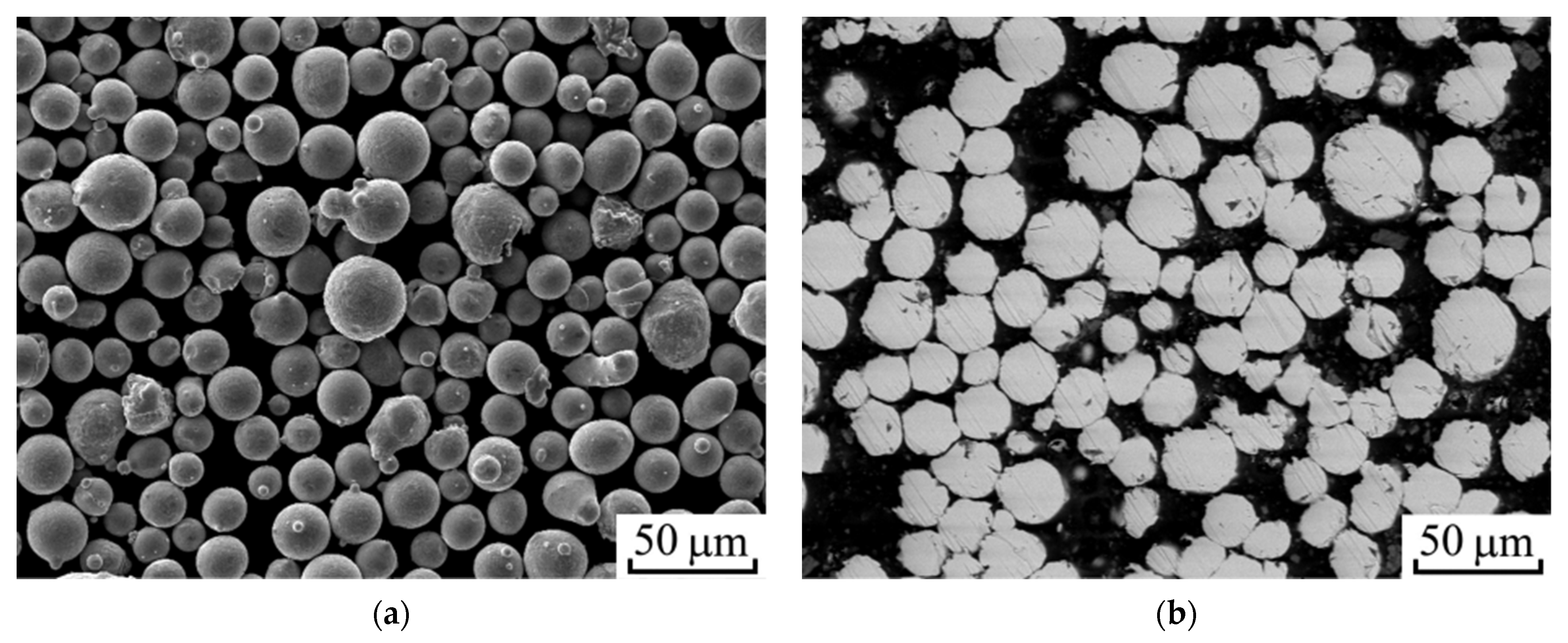
2.1. Powder and Coating Deposition
2.2. Microstructure Characterization
2.3. Electrochemical Characterization
3. Results and Discussions
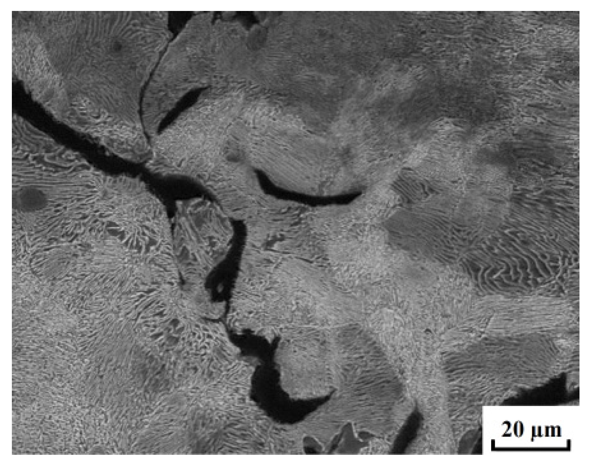
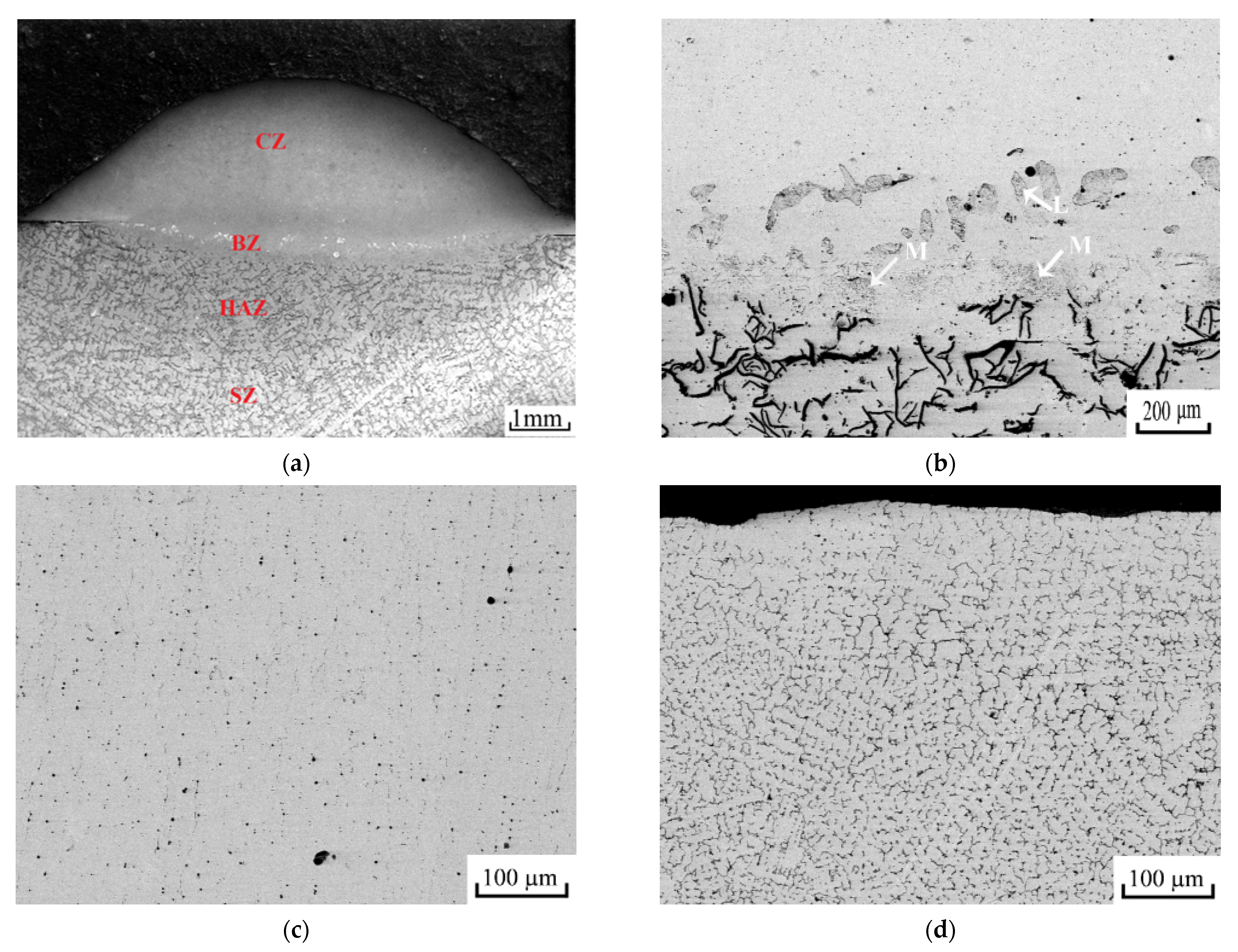
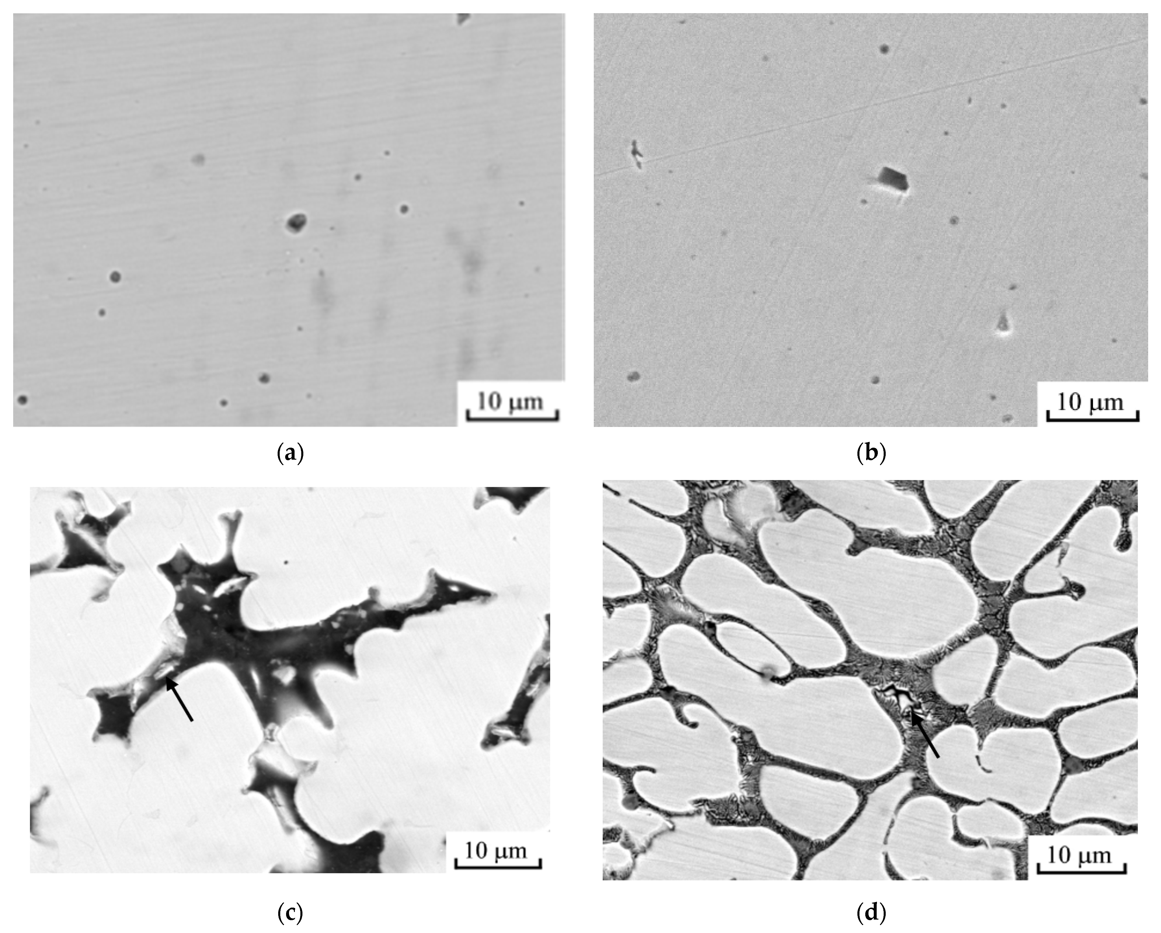
3.1. Microstructure of the HEA Coatings
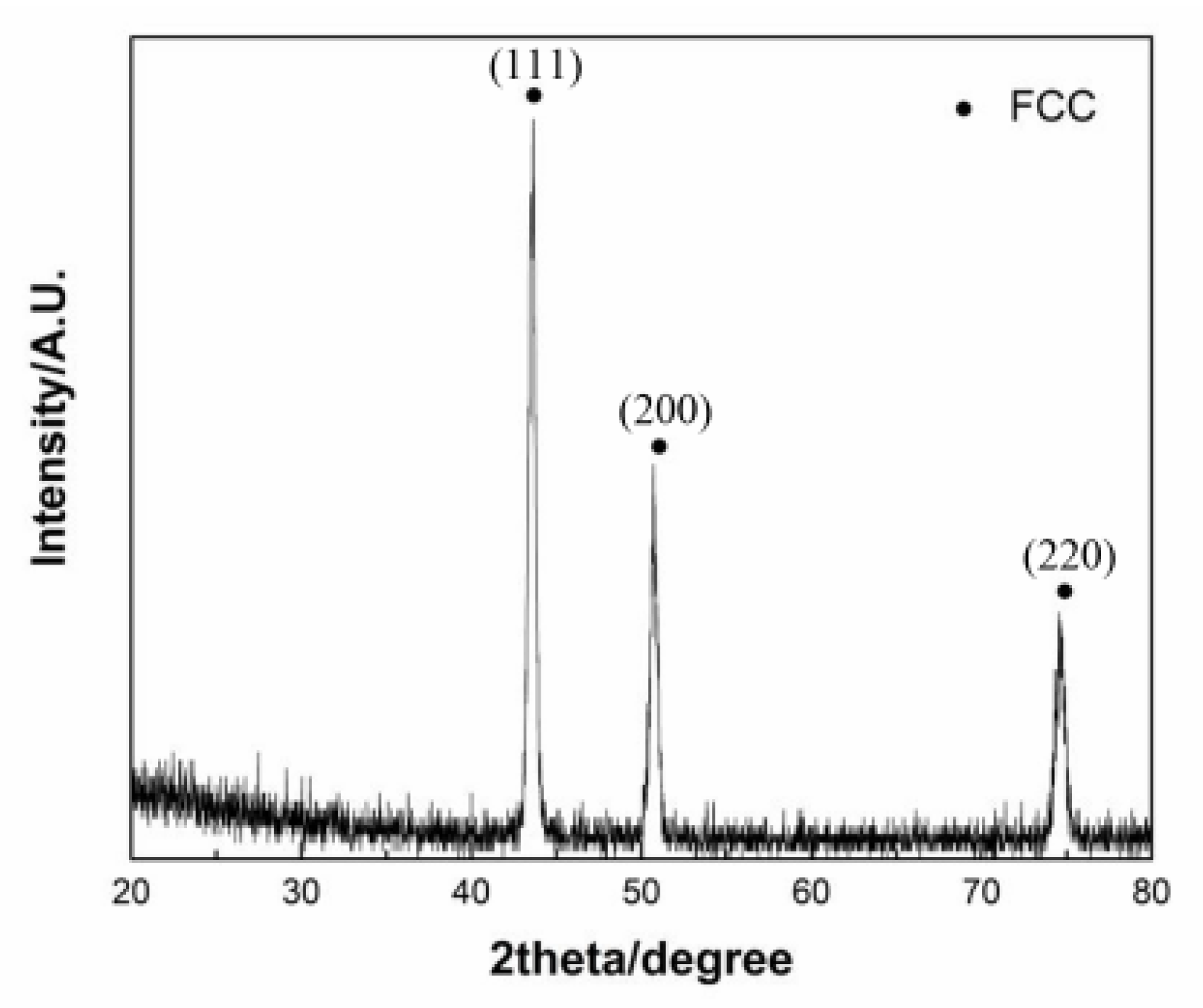
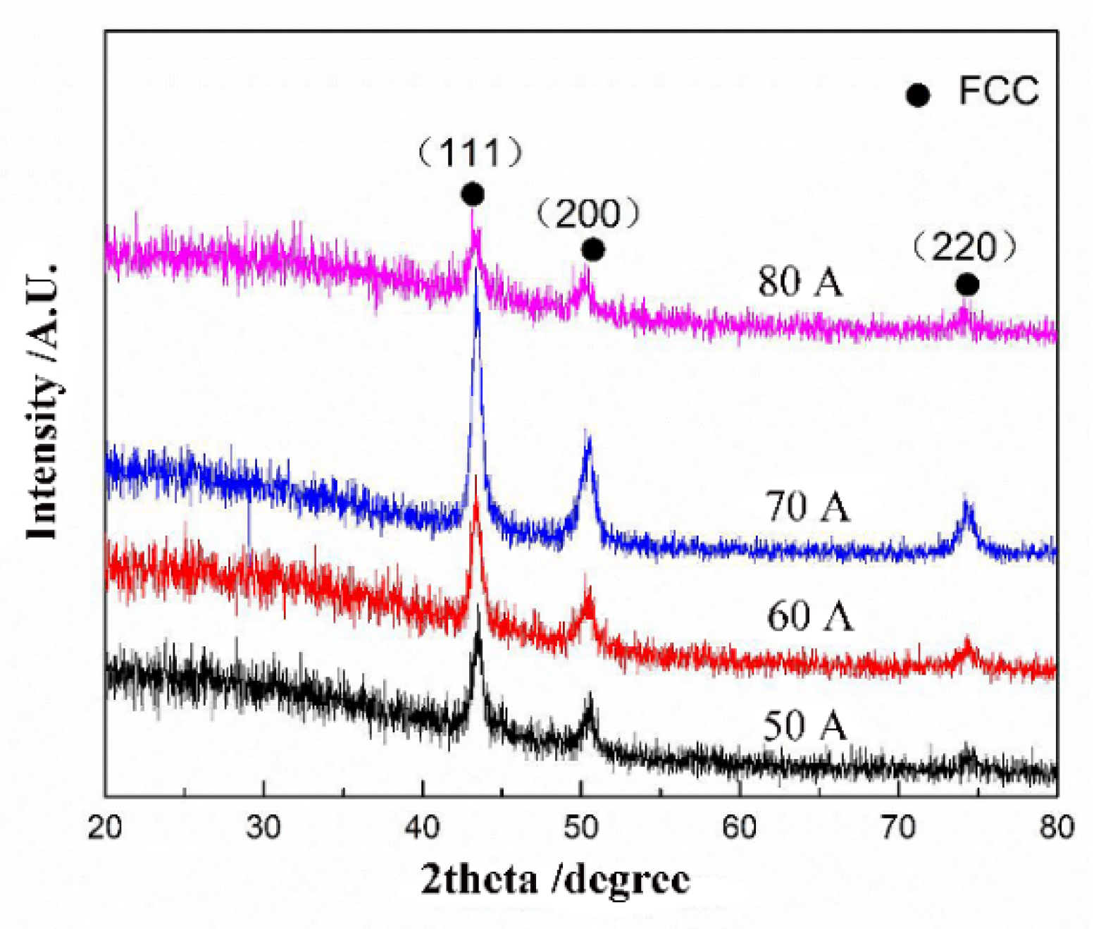
3.2. Phases
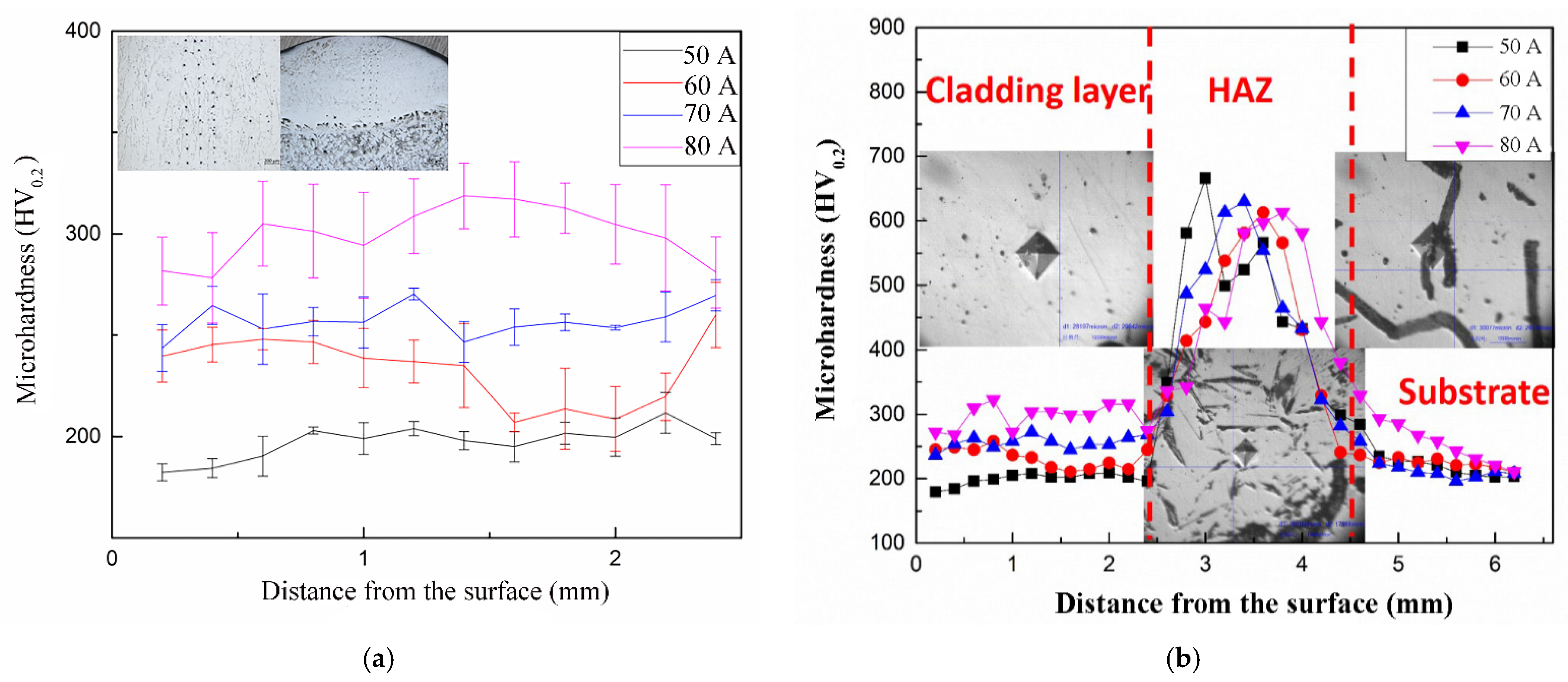
3.3. Microhardness
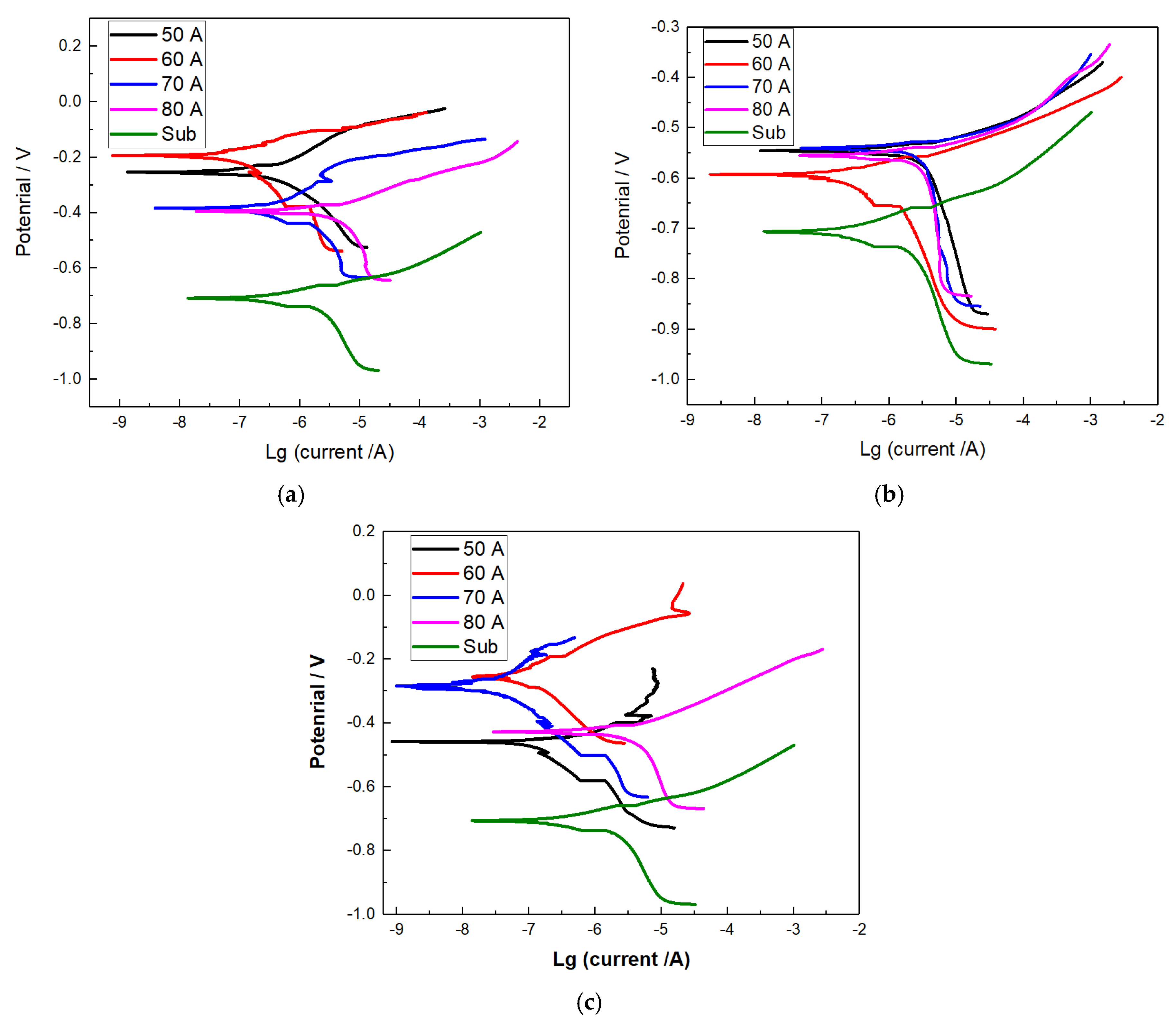
3.4. Electrochemical Corrosion
4. Conclusions
Author Contributions
Funding
Institutional Review Board Statement
Informed Consent Statement
Data Availability Statement
Conflicts of Interest
References
- Yeh, J.W.; Chen, S.K.; Lin, S.J.; Gan, J.Y.; Chin, T.S.; Shun, T.T.; Tsau, C.H.; Chang, S.Y. Nanostructured high-entropy alloys with multiple principal elements: Novel alloy design concepts and outcomes. Adv. Eng. Mater. 2004, 6, 299–303. [Google Scholar] [CrossRef]
- Feng, X.R.; Cui, X.F.; Jin, G.; Zheng, W.; Cai, Z.B.; Wen, X.; Lu, B.W.; Li, J.M. Underwater laser cladding in full wet surroundings for fabrication of nickel aluminum bronze coatings. Surf. Coat. Technol. 2018, 333, 104–114. [Google Scholar] [CrossRef]
- Yang, T.; Zhao, Y.; Tong, Y.; Jiao, Z.; Wei, J.; Cai, J.; Han, X.; Chen, D.; Hu, A.; Kai, J.; et al. Multicomponent intermetallic nanoparticles and superb mechanical behaviors of complex alloys. Science 2018, 362, 933–937. [Google Scholar] [CrossRef] [PubMed] [Green Version]
- Fu, Z.; Jiang, L.; Wardini, J.L.; MacDonald, B.E.; Wen, H.; Xiong, W.; Zhang, D.; Zhou, Y.; Rupert, T.J.; Chen, W.; et al. A high-entropy alloy with hierarchical nanoprecipitates and ultrahigh strength. Sci. Adv. 2018, 4, 8712. [Google Scholar] [CrossRef] [PubMed] [Green Version]
- Zou, Y.; Ma, H.; Spolenak, R. Ultrastrong ductile and stable high-entropy alloys at small scales. Nat. Commun. 2015, 6, 7748. [Google Scholar] [CrossRef] [PubMed] [Green Version]
- Yao, Y.; Huang, Z.; Xie, P.; Lacey, S.D.; Jacob, R.J.; Xie, H.; Chen, F.; Nie, A.; Pu, T.; Rehwoldt, M.; et al. Carbothermal shock synthesis of high-entropy-alloy nanoparticles. Science 2018, 359, 1489–1494. [Google Scholar] [CrossRef] [Green Version]
- El-Atwani, O.; Li, N.; Li, M.; Devaraj, A.; Baldwin, J.K.S.; Schneider, M.M.; Sobieraj, D.; Wróbel, J.S.; Nguyen-Manh, D.; Maloy, S.A.; et al. Outstanding radiation resistance of tungsten-based high-entropy alloys. Sci. Adv. 2019, 5, 2002. [Google Scholar] [CrossRef] [Green Version]
- Qiu, Y.; Thomas, S.; Gibson, M.A.; Fraser, H.L.; Birbilis, N. Corrosion of high entropy alloys. NPJ Mater. Degrad. 2017, 1, 15. [Google Scholar] [CrossRef]
- Chuang, M.; Tsai, M.; Wang, W.; Lin, S.; Yeh, J. Microstructure and wear behavior of AlxCo1.5CrFeNi1.5Tiy high-entropy alloys. Acta Mater. 2011, 59, 6308–6317. [Google Scholar] [CrossRef]
- Piglione, A.; Dovgyy, B.; Liu, C.; Gourlay, C.M.; Hooper, P.A.; Pham, M.S. Printability and microstructure of the CoCrFeMnNi high-entropy alloy fabricated by laser powder bed fusion. Mater. Let. 2018, 224, 22–25. [Google Scholar] [CrossRef]
- Yim, D.; Sathiyamoorthi, P.; Hong, S.J.; Kim, H.S. Fabrication and mechanical properties of TiC reinforced CoCrFeMnNi high-entropy alloy composite by water atomization and spark plasma sintering. J. Alloys Compd. 2019, 781, 389–396. [Google Scholar] [CrossRef]
- Lai, C.H.; Lin, S.J.; Yeh, J.W.; Chang, S.Y. Preparation and Characterization of AlCrTaTiZr Multi-Element Nitride Coatings. Surf. Coat. Technol. 2006, 20, 3275. [Google Scholar] [CrossRef]
- Chen, T.K.; Shun, T.T.; Yeh, J.W.; Wong, M.S. Nanostructured Nitride Films of Multi-Element High-Entropy Alloys by Reactive DC Sputtering. Surf. Coat. Technol. 2004, 188, 189–193. [Google Scholar] [CrossRef]
- Meghwal, A.; Anupam, A.; Murty, B.S.; Berndt, C.C.; Ang, A. Thermal Spray High-Entropy Alloy Coatings: A Review. J. Therm. Spray. Technol. 2020, 29, 857–893. [Google Scholar] [CrossRef]
- Shu, F.; Wang, B.; Zhao, H.; Zhang, J. Effects of Line Energy on Microstructure and Mechanical Properties of CoCrFeNiBSi High-Entropy Alloy Laser Cladding Coatings. J. Therm. Spray. Technol. 2020, 29, 789–797. [Google Scholar] [CrossRef]
- Ye, X.H.; Ma, M.X.; Cao, Y.X.; Liu, W.J.; Ye, X.H.; Gu, Y. The Property Research on High-entropy Alloy AlxFeCoNiCuCr Coating by Laser Cladding. Phys. Procedia. 2011, 12, 303–312. [Google Scholar] [CrossRef] [Green Version]
- Lehtonen, J.; Koivuluoto, H.; Ge, Y.; Juselius, A.; Hannula, S.P. Cold Gas Spraying of a High-Entropy CrFeNiMn Equiatomic. Alloy. Coat. 2020, 10, 53. [Google Scholar] [CrossRef] [Green Version]
- Chen, L.J.; Bobzin, K.; Zhou, Z.; Zhao, L.D.; Mehmet, Ö.; Tim, K.; Tan, Z.; He, D.Y. Wear behavior of HVOF-sprayed Al0.6TiCrFeCoNi high entropy alloy coatings at different temperatures. Surf. Coat. Technol. 2019, 358, 215–222. [Google Scholar] [CrossRef]
- Zhang, J.; Liu, M.; Song, J.; Deng, C.; Deng, C. Microstructure and corrosion behavior of Fe-based amorphous coating prepared by HVOF. J. Alloys Compd. 2017, 721, 506–511. [Google Scholar] [CrossRef]
- Zhang, B.S.; Cheng, J.B.; Xu, B.S. (CuCoCrFeNi) 95B5 highentropy alloy coatings prepared by plasma transferred arc cladding process. Rare Metal Mater. Eng. 2014, 43, 1128–1132. [Google Scholar]
- Kim, Y.S.; Park, H.J.; Mun, S.C.; Jumaev, E.; Hong, S.H.; Song, G.; Kim, J.T.; Park, Y.K.; Kim, K.S.; Jeong, S.I.; et al. Investigation of structure and mechanical properties of TiZrHfNiCuCo high entropy alloy thin films synthesized by magnetron sputtering. J. Alloys Compd. 2019, 797, 834–841. [Google Scholar] [CrossRef]
- Lin, T.S.; He, P.; Wang, X.R.; Wang, Z.Q.; Shi, Y. Microstructure and wear properties of CuNiSiTiZr high-entropy alloy coatings on TC11 titanium alloy produced by eletrospark-computer numerical control deposited process. Surf. Coat. Technol. 2015, 283, 156–161. [Google Scholar]
- Cheng, J.B.; Liu, D.; Liang, X.B.; Chen, Y.X. Evolution of microstructure and mechanical properties of in situ synthesized TiC-TiB2/CoCrCuFeNi high entropy alloy coatings. Surf. Coat. Technol. 2015, 281, 109–116. [Google Scholar] [CrossRef]
- Sudha, C.; Shankar, P.; Rao, R.V.S.; Thirumurugesan, R.; Vijayalakshmi, M.; Raj, B. Microchemical and microstructural studies in a PTA weld overlay of Ni–Cr–Si–B alloy on AISI 304L stainless steel. Surf. Coat. Technol. 2008, 202, 2103–2112. [Google Scholar] [CrossRef]
- Stern, M.; Geary, A.L. Electrochemical polarization I. A theoretical analysis of the shape of polarization curves. J. Electrochem. Soc. 1957, 104, 56. [Google Scholar] [CrossRef]
- Liu, M.J.; Zhang, G.; Lu, Y.H.; Han, J.Q.; Li, G.R.; Li, C.J.; Yang, G.J. Plasma spray-physical vapor deposition toward advanced thermal barrier coatings: A review. Rare Metals 2020, 39, 479–497. [Google Scholar] [CrossRef]
- Lin, D.Y.; Zhang, N.N.; He, B.; Gong, X.; Gong, X.; Zhang, Y.; Li, D.Y.; Dong, F.Y. Structural Evolution and Performance Changes in FeCoCrNiAlNbx High-Entropy Alloy Coatings Cladded by Laser. J. Therm. Spray. Technol. 2017, 26, 2005–2012. [Google Scholar] [CrossRef]
- Zhang, W.R.; Peter, K.L.; Zang, Y. Science and technology in high-entropy alloys. Sci. China Mater. 2018, 1, 1–21. [Google Scholar] [CrossRef] [Green Version]
- Wang, C.L.; Gao, Y.; Wang, R.; Wei, D.Q.; Cai, M.; Fu, Y.K. Microstructure of laser-clad Ni60 cladding layers added with different amounts of rare-earth oxides on 6063 Al alloys. J. Alloys Compd. 2018, 740, 1099–1107. [Google Scholar] [CrossRef]
- Kivy, B.M.; Zaeem, A. Generalized stacking fault energies, ductilities, and twinnabilities of CoCrFeNi-based face-centered cubic high entropy alloys. Scr. Mater. 2017, 139, 83–86. [Google Scholar] [CrossRef]
- Wu, W.; Jiang, L.; Jiang, H.; Pan, X.M.; Cao, Z.Q.; Deng, D.W.; Wang, T.M.; Li, T.J. Phase Evolution and Properties of Al2CrFeNiMox High-Entropy Alloys Coatings by Laser Cladding. J. Therm. Spray. Technol. 2015, 24, 1333–1340. [Google Scholar] [CrossRef]
- Gao, P.H.; Chen, B.Y.; Zhang, B.; Yang, Z.; Guo, Y.C.; Li, J.P.; Liang, M.X.; Li, Q.P. Preparations of iron-based alloy coatings on grey cast iron through plasma transfer arc welding. J. Adhes. Sci. Technol. 2021. [Google Scholar] [CrossRef]
- Gao, P.H.; Chen, B.Y.; Zeng, S.C.; Yang, Z.; Guo, Y.C.; Liang, M.X.; Xu, T.; Li, J.P. Effect of Vacuum Annealing on the Nickel-Based Coatings Deposited on a CGI Cast Iron through Atmospheric Plasma Spraying. Metals 2020, 10, 963. [Google Scholar] [CrossRef]
- Kaseem, M.; Ko, Y.G. Formation of flower-like structures for optimizing the corrosion resistance of Mg alloy. Mater. Lett. 2018, 221, 196–200. [Google Scholar] [CrossRef]
- Shi, Y.Z.; Yang, B.; Liaw, P.K. Corrosion resistant high entropy alloys: A review. Metals 2013, 7, 43. [Google Scholar] [CrossRef] [Green Version]
- Liu, J.; LI, J.; Cheng, X.; Wang, H. Effect of dilution and macro-segregation on corrosion resistance of laser clad AerMet100 steel coating on 300M steel substrate. Surf. Coat. Technol. 2017, 325, 352–359. [Google Scholar] [CrossRef]
- Song, C.H.; Gan, Z.H.; Lu, Z.H.; Chen, H.J.; Huang, F. Preparation and electrochemical properties of AlMgZnSnPbCuMnNi high entropy alloys with low free corrosion potentials. J. Mater. Sci. Eng. 2011, 29, 747–752. [Google Scholar]
- Gao, J.; Jiang, Y.; Deng, B.; Zhang, W.; Zhong, C.; Li, J. Investigation of selective corrosion resistance of aged lean duplex stainless steel 2101 by non-destructive electrochemical techniques. Electrochim. Acta 2009, 54, 5830–5835. [Google Scholar] [CrossRef]
- Hitz, C.; Lasia, A. Experimental study and modeling of impedance of the her on porous Ni electrodes. J. Electroanal. Chem. 2001, 500, 213–222. [Google Scholar] [CrossRef]
- Niu, B.; Shi, P.; E, S.S.; Wei, D.H.; Li, Q.; Chen, Y. Preparation and characterization of HA sol–gel coating on MAO coated AZ31 alloy. Surf. Coat. Technol. 2016, 286, 42–48. [Google Scholar] [CrossRef]


| Element | Co | Cr | Fe | Ni | Mn |
|---|---|---|---|---|---|
| wt.% | 20.58 | 18.35 | 19.98 | 20.49 | 20.48 |
| Element | C | Si | Mn | Cu | Sn | S | Fe |
|---|---|---|---|---|---|---|---|
| wt.% | 3.3 | 2.0 | 0.45 | 0.5 | 0.1 | 0.05 | balance |
| Plasma Arc (A) | Scanning Speed (mm/min) | Ion Gas Flow (L/min) | Protection Gas Flow (L/min) | Powder Feeding Rate (rad/min) | Distance from Torch Exit to Substrate (mm) |
|---|---|---|---|---|---|
| 50, 60, 70, 80 | 150 | 1.5 | 10 | 20 | 10 |
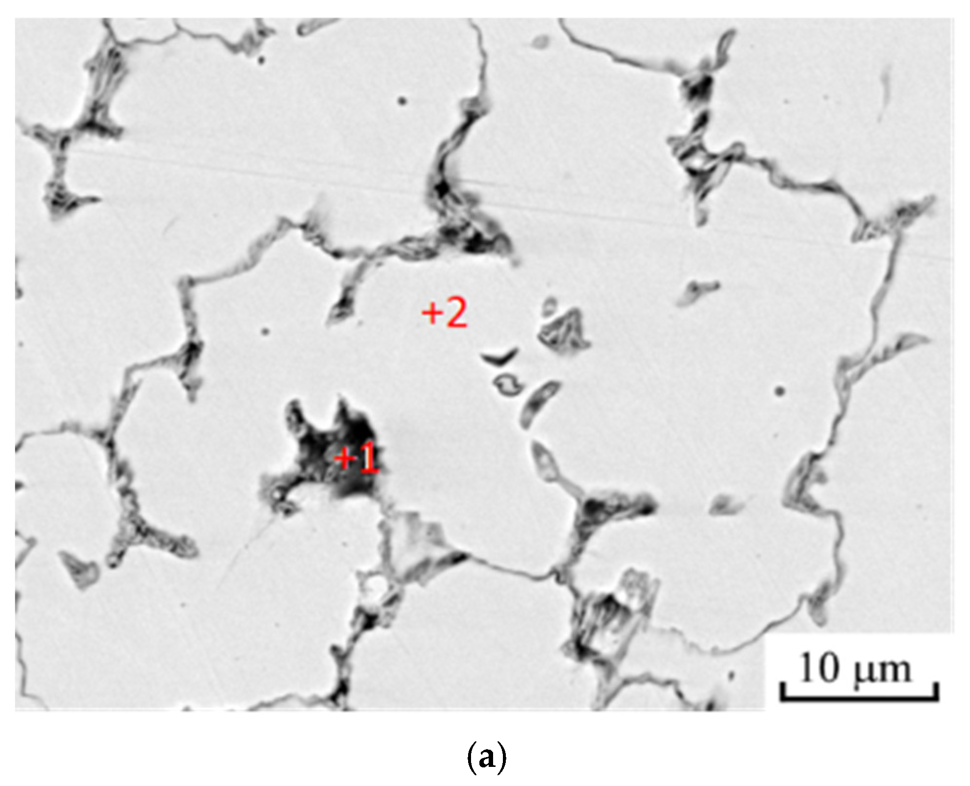
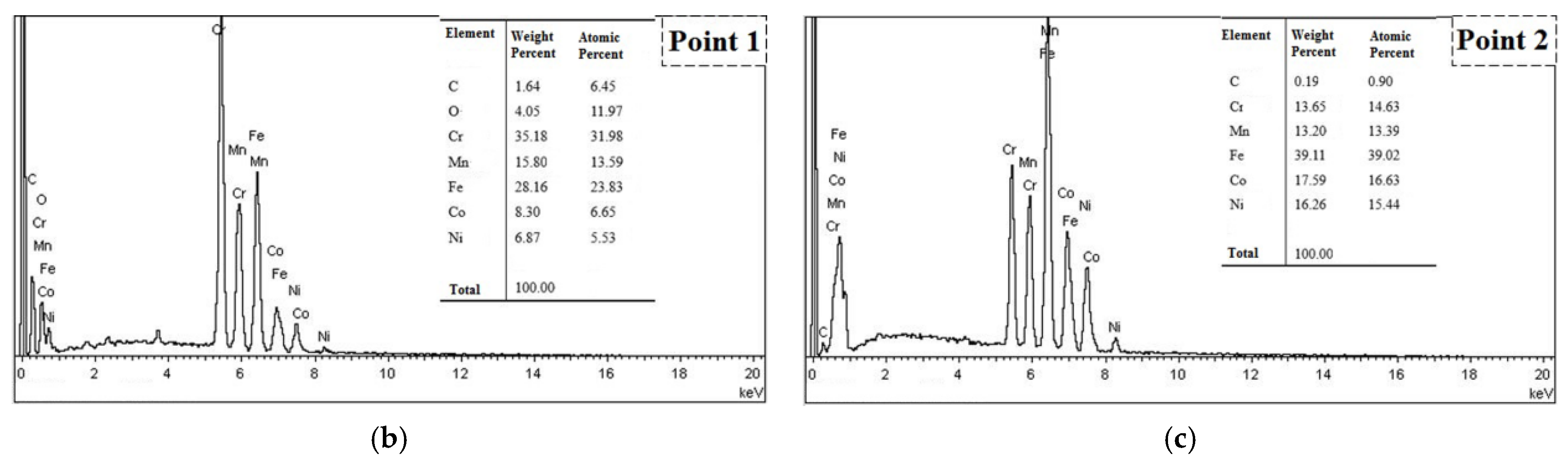
| Element (wt.%) | C | O | Co | Cr | Fe | Ni | Mn |
|---|---|---|---|---|---|---|---|
| Powder | - | - | 20.58 | 18.35 | 19.98 | 20.49 | 20.48 |
| Point 1 | 1.64 | 4.05 | 35.18 | 15.80 | 28.16 | 8.30 | 6.87 |
| Point 2 | 0.19 | - | 13.65 | 13.20 | 39.11 | 17.59 | 16.26 |
| Lattice Parameters | Powder | Coatings | |||
|---|---|---|---|---|---|
| 50 A | 60 A | 70 A | 80 A | ||
| Å | 3.59751 ± 0.00018 | 3.60495 ± 0.00021 | 3.59809 ± 0.00017 | 3.59778 ± 0.00019 | 3.59709 ± 0.00018 |
| Plasma Current/A | Dendritic Crystal Width/μm |
|---|---|
| 50 A | 120 ± 42 |
| 60 A | 43 ± 25 |
| 70 A | 16 ± 4 |
| 80 A | 6 ± 2 |
| Zone | Plasma Current/A | 50 | 60 | 70 | 80 |
|---|---|---|---|---|---|
| Bonding Zone | Ecorr/V | −0.25 ± 0.08 | −0.294 ± 0.10 | −0.387 ± 0.03 | −0.391 ± 0.05 |
| Icorr/mA·mm−2 | 1.085 ± 0.3 × 10⁻⁶ | 5.37 ± 0.7 × 10⁻⁶ | 3.596 ± 0.6 × 10⁻⁶ | 1.36 ± 0.08 × 10⁻⁶ | |
| Heat Affected Zone | Ecorr/V | −0.545 ± 0.04 | −0.592 ± 0.12 | −0.539 ± 0.07 | 0.0554 ± 0.007 |
| Icorr/mA·mm−2 | 7.53 ± 0.2 × 10⁻⁷ | 1.357 ± 0.3 × 10⁻⁶ | 3.046 ± 0.03 × 10⁻⁶ | 2.903 ± 0.4 × 10⁻⁶ | |
| Coating Zone | Ecorr/V | −0.284 ± 0.01 | −0.253 ± 0.05 | −0.458 ± 0.009 | −0.428 ± 0.08 |
| Icorr/mA·mm−2 | 9.206 ± 0.14 × 10⁻⁷ | 9.075 ± 0.06 × 10⁻⁷ | 5.295 ± 0.12 × 10⁻⁶ | 1.81 ± 0.18 × 10⁻⁶ |
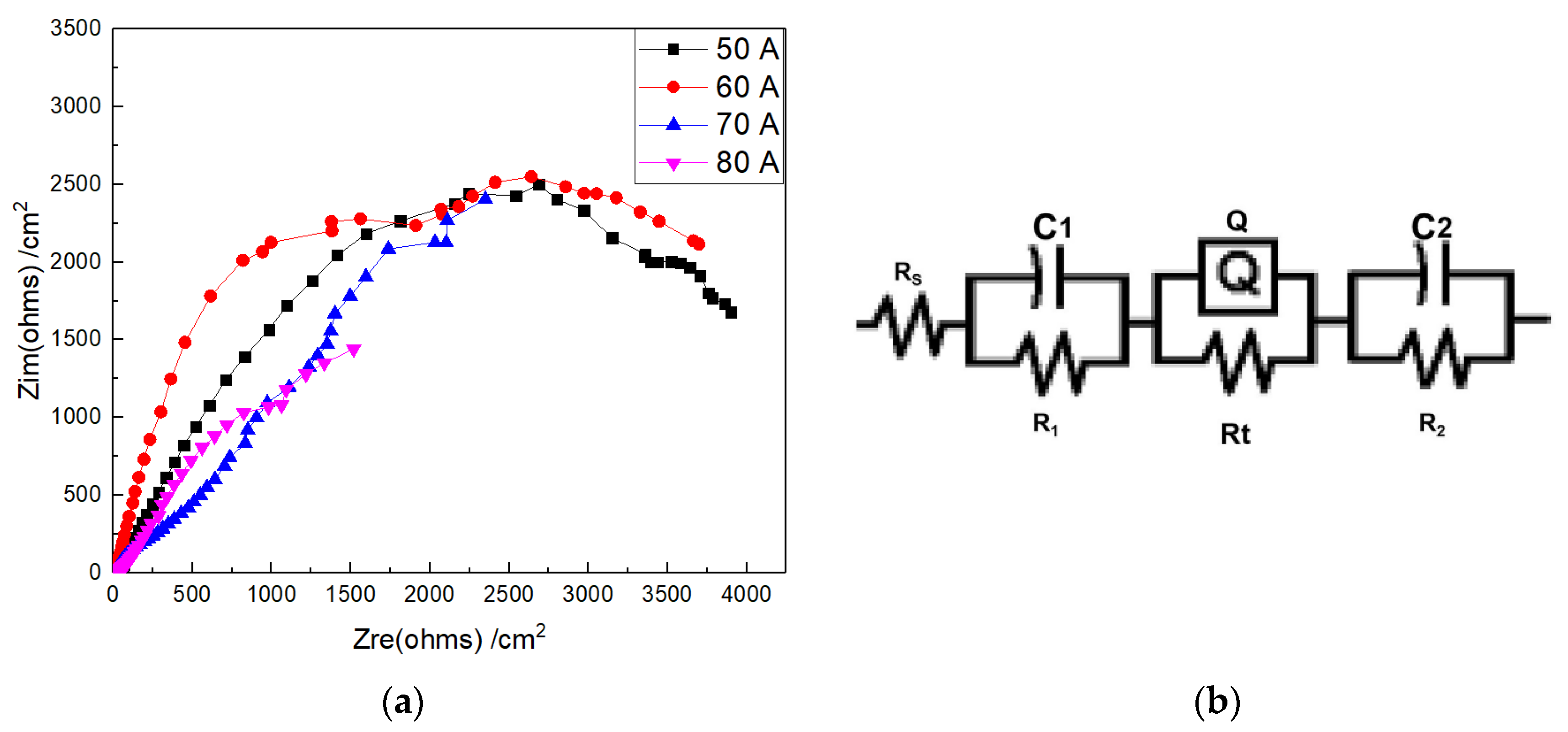
| Coatings Deposition Plasma Arc Current/A | Rs/Ω | C1/C | R1/Ω | Q/C | n | Rt/Ω | C2/C | R2/Ω |
|---|---|---|---|---|---|---|---|---|
| 50 | 18.86 ± 1.2 | 1.142 ± 0.5 × 10⁻³ | 541.1 ± 5.2 | 2.253 ± 0.12 × 10⁻⁴ | 0.6824 ± 0.13 | 5073 ± 25 | 7.745 ± 0.21 × 10⁻⁴ | 16.48 ± 2.21 |
| 60 | 14.79 ± 0.8 | 5.006 ± 0.3 × 10⁻⁴ | 153.7 ± 8.2 | 5.235 ± 0.22 × 10⁻⁴ | 0.5998 ± 0.08 | 9711 ± 46 | 4.04 ± 0.11 × 10⁻⁴ | 200.8 ± 13.2 |
| 70 | 15.35 ± 1.0 | 2.599 ± 0.8 × 10⁻⁵ | 7.126 ± 1.0 | 1.629 ± 0.08 × 10⁻⁴ | 0.685 ± 0.21 | 6043 ± 16 | 6.471 ± 0.12 × 10⁻⁵ | 63.48 ± 1.36 |
| 80 | 14.20 ± 1.3 | 2.334 ± 1.0 × 10⁻⁵ | 13.03 ± 0.6 | 1.631 ± 0.26 × 10⁻⁴ | 0.7025 ± 0.14 | 5672 ± 25 | 2.418 ± 0.176 × 10⁻⁴ | 670.2 ± 9.86 |
Publisher’s Note: MDPI stays neutral with regard to jurisdictional claims in published maps and institutional affiliations. |
© 2021 by the authors. Licensee MDPI, Basel, Switzerland. This article is an open access article distributed under the terms and conditions of the Creative Commons Attribution (CC BY) license (https://creativecommons.org/licenses/by/4.0/).
Share and Cite
Gao, P.-H.; Fu, R.-T.; Chen, B.-Y.; Zeng, S.-C.; Zhang, B.; Yang, Z.; Guo, Y.-C.; Liang, M.-X.; Li, J.-P.; Lu, Y.-Q.; et al. Corrosion Resistance of CoCrFeNiMn High Entropy Alloy Coating Prepared through Plasma Transfer Arc Claddings. Metals 2021, 11, 1876. https://doi.org/10.3390/met11111876
Gao P-H, Fu R-T, Chen B-Y, Zeng S-C, Zhang B, Yang Z, Guo Y-C, Liang M-X, Li J-P, Lu Y-Q, et al. Corrosion Resistance of CoCrFeNiMn High Entropy Alloy Coating Prepared through Plasma Transfer Arc Claddings. Metals. 2021; 11(11):1876. https://doi.org/10.3390/met11111876
Chicago/Turabian StyleGao, Pei-Hu, Rui-Tao Fu, Bai-Yang Chen, Sheng-Cong Zeng, Bo Zhang, Zhong Yang, Yong-Chun Guo, Min-Xian Liang, Jian-Ping Li, Yong-Qing Lu, and et al. 2021. "Corrosion Resistance of CoCrFeNiMn High Entropy Alloy Coating Prepared through Plasma Transfer Arc Claddings" Metals 11, no. 11: 1876. https://doi.org/10.3390/met11111876