Article

Synthesizing Ti–Ni Alloy Composite Coating on Ti–6Al–4V Surface from Laser Surface Modification

1
Department of Mechanical and Aerospace Engineering, Missouri University of Science and Technology, Rolla, MO 65409, USA
2
Department of Materials Science and Engineering, Missouri University of Science and Technology, Rolla, MO 65409, USA
*
Author to whom correspondence should be addressed.
Metals 2023, 13(2), 243; https://doi.org/10.3390/met13020243
Submission received: 28 December 2022 / Revised: 19 January 2023 / Accepted: 23 January 2023 / Published: 27 January 2023
(This article belongs to the Special Issue Laser-Assisted Processing of Metals and Alloys)

Abstract

:
In this work, a Ni-alloy Deloro-22 was laser-deposited on a Ti–6Al–4V bar substrate with multiple sets of laser processing parameters. The purpose was to apply laser surface modification to synthesize different combinations of ductile TiNi and hard Ti2Ni intermetallic phases on the surface of Ti–6Al–4V in order to obtain adjustable surface properties. Scanning electron microscopy, energy dispersion spectroscopy, and X-ray diffraction were applied to reveal the deposited surface microstructure and phase. The effect of processing parameters on the resultant compositions of TiNi and Ti2Ni was discussed. The hardness of the deposition was evaluated, and comparisons with the Ti–6Al–4V bulk part were carried out. They showed a significant improvement in surface hardness on Ti–6Al–4V alloys after laser processing, and the hardness could be flexibly adjusted by using this laser-assisted surface modification technique.

1. Introduction

A Ti–6Al–4V alloy is a type of popular engineering alloy widely used in various industrial areas, including aerospace, marine, and biomedical engineering, due to its high strength-to-weight ratio, low density, and excellent corrosion resistance [1,2]. However, the surface hardness often acts as a limitation on the applications of Ti–6Al–4V [3]. Applications for Ti alloy surface modification have been reported to improve the behavior of Ti implants, such as the creation of surface nanostructures to improve the osseointegration process [4,5]. On the other hand, surface modification is also an important approach to strengthen the surface of Ti alloys. In this way, techniques including surface mechanical attrition treatment (SMAT) and ultrasonic shot peening (USSP) have been applied [6,7]. Apart from creating plastic deformation at the surface, lasers have also become an important tool for modifying the surface characteristics of metal parts [8,9] by creating metallic coating layers based on the rapid development of laser applications. Typical processing methods such as laser-based directed energy deposition and laser cladding have been developed in the application of modifying surfaces and combining multiple metal parts with strong metallurgical bonding [8,10]. Compared with mechanical approaches, laser processing can introduce a much wider range of harder materials to the Ti alloy surface with strong bonding. Based on the wide application range, the surface strength of Ti–6Al–4V has been improved via multiple types of coating alloys using laser cladding, including Co-based alloys, Ni-based alloys, and ceramics-reinforced metal matrix composites such as with TiC and SiC [11,12,13,14].
Apart from the aforementioned alloys, another useful method to improve and modify the surface properties of Ti–6Al–4V is to create TiNi-based intermetallic phases on the surface using laser techniques [15]. A Ti–Ni system includes multiple types of intermetallics [16], which can then result in various types of new materials at the surface via different processing conditions. In particular, TiNi is ductile and possesses multiple special properties as it is a major phase of the TiNi-type shape memory alloy with a shape memory effect, superelasticity, and high corrosion resistance, while Ti2Ni is a hard phase that can significantly improve the hardness of components [15,16]. Due to the cost and difficulty in traditional manufacturing, it can be practical to use the deposition processing of Ti–Ni alloy systems as surface coating materials [15]. A layer made of a combination of TiNi and Ti2Ni (namely TixNiy) formed on a Ti–6Al–4V surface will give a more comprehensive surface performance. The whole part can, therefore, possess both advantages of Ti–6Al–4V away from the surface and TiNi alloys at the surface. Wang et al. [15] applied wire deposition using a combination of Ti and Ni wire. While for powder-based laser surface modification processes, a preplacing powder approach was previously applied in the laser cladding of Ti–6Al–4V alloys to create multiple types of Ti–Ni intermetallics, other hard phases, such as TiB2 and TiC, can be involved according to the easy-to-mix feature of powder materials [17,18]. On the other hand, using the blown powder method during laser cladding has several advantages. The blown powder method can be easier for performing selective local coating and repairing on a non-flat surface [19]. Mokgalaka et al. have attempted to use Ti and Ni elemental powders as feedstock for blown powder laser deposition on a Ti–6Al–4V surface [20,21]. Since the laser power can create a melt pool on the Ti–6Al–4V substrate that can provide plenty of Ti elements, rather than using Ti–Ni alloys as the raw materials, we may also try using Ni or Ni-alloy alone as the feedstock to synthesize a TiNi-based coating at the Ti–6Al–4V surface by making use of the laser-melted Ti from the substrate, which makes the feedstock simpler. However, limited work has been carried out from this perspective. Liu et al. [22] deposited a type of Ni–Cr–Fe alloy powder on a TA2 substrate, while the effect of parameters on the resultant microstructure and mechanical properties was not included.
In this work, a type of Ni-based alloy named Deloro-22 with 95 wt.% Ni and Si and B as major secondary elements was used to form a TixNiy coating on Ti–6Al–4V using the blown powder-based laser deposition processing technique for surface modification with multiple parameters. For single-layer TiNi-based coating on Ti–6Al–4V, the dilution effect can be utilized so that only a single type of Ni-alloy powder is enough to make the study of the surface modification process simpler. It is expected that the composition relation between Ti and Ni can be adjusted by laser parameters, and using processing parameters to flexibly control the combination is of great interest for different service and loading conditions. Therefore, the influence of parameters on the resultant phases and properties of the TixNiy coating deposited by using Deloro-22 alloy powder will be investigated. Meanwhile, minor alloying elements such as B can also be introduced by Deloro-22 alloy powders into the melt pool, and B can form borides with Ti in the Ti–B system [23]. Adding hard ceramics such as TiB can act as a strengthening phase within the Ti-alloy coating [24]. Depositing near-pure Ni-based alloy powder with minor elements can result in both the main Ti–Ni-based structure and a minor reinforcement due to the reaction of minor elements with Ti. The combined effects of the main phases of TixNiy and minor phases due to the existence of minor elements will be of interest to study in this work to reveal more adjustable properties of depositing Ni-based alloys on Ti–6Al–4V for surface modification. As mentioned in the previous work, the minor element of Si is expected to be effective in improving the fluidity during the deposition process and reducing the possibility of porosity [25]. In this work, different laser processing parameters were applied to synthesize TixNiy composite coatings with various properties under multiple parameters using the Deloro-22 powder alone. The processing–property relationship was investigated by using various material characterization tools in detail.

2. Materials and Methods

The laser deposition process was performed using an in-house-developed laser powder deposition system. The system mainly includes an IPG photonics fiber laser (IPG Photonics, Oxford, MA, USA) with a maximum operating power of 1kW, an Ar-purged chamber, a powder feeder with Ar as the carrier gas, and a CNC-controlled gantry that can take the substrate material to travel linearly in x, y, and z directions. Figure 1 indicates the working mechanism of the deposition process. Figure 1a is a 3D view of the fabrication process, while Figure 1b indicates a cross-sectional view of the deposition track formed by the laser-induced melt pool and the gas-delivered Deloro-22 powders.
A Ti–6Al–4V cuboid bar was used as the substrate for the experiment. The dimension of the Ti–6Al–4V bar was 3 × 1 × 1/4 inches. Gas-atomized Deloro-22 powder was supplied by Kennametal Inc. Powder samples were collected and imaged using a Hitachi S4700 scanning electron microscope (SEM) (Hitachi Ltd., Tokyo, Japan), which is shown in Figure 2a. From the SEM powder image, it can be seen that most of the powder particles were highly spherical. Figure 2b shows the size distribution of Deloro-22 powders. The d50 value of the powder sample was calculated as approximately 120 μm, and the nominated chemical composition is tabulated in Table 1. This Ni-alloy powder mainly consisted of approximately 95 wt.% Ni and minor compositions of Si, B, Fe, and C.
The laser was applied to create a Ti-rich melt pool on the Ti–6Al–V substrate, and at the same time, the Ni-dominated Deloro-22 powder stream was fed into the melt pool to realize the in situ synthesis of the Ti–Ni alloy matrix coating by making use of the melted Ti from the substrate and the dilution effect, as described in Figure 1b. The laser beam diameter was set at about 3.5 mm. The standoff distance was fixed at 10 mm in this work. The laser power of 900 W and three different travel speeds were applied. Single tracks deposited under the travel speed of 100 mm/min, 150 mm/min, and 200 mm/min were labeled as SL, SM, and SH, respectively. The powder feed rate with respect to travel distance was kept at a steady state of around 0.02 g/mm. A variation in travel speed can create different energy densities, which are expected to show the difference between Ti and Ni elements within the melt pool, which will then result in variations in phase formation. After the deposition was finished and cooled down to room temperature, those cross-sections of deposition tracks were sliced using a Hansvedt DS-2 electrical discharge machine (EDM) (Hansvedt Industries Inc., Rantoul, IL, USA). The sliced parts were then ground with 320, 400, 600, and 800 grit SiC sandpapers, polished with diamond suspension from 9 μm to 1 μm, and finalized using 0.05 μm colloidal alumina for metallographic observation. The grinding and polishing were conducted by using a Buehler Automet 250 grinder/polisher machine (Buehler, Lake Bluff, IL, USA). The microstructure and elemental distribution at different locations of the deposition track and primary and secondary phases were studied using a Helios NanoLab 600 SEM (Thermo Fisher Scientific, Waltham, MA, USA) equipped with an energy-dispersive X-ray spectroscopy (EDS) detector. A TFS Hydra SEM (Thermo Fisher Scientific, Waltham, MA, USA) was used for focused ion beam (FIB) cross-section and EDS mapping. X-ray diffraction (XRD) results were obtained using a Philips X’pert MRD diffractometer to illustrate the existence of TixNiy phases. Vickers hardness values were obtained using a Struers Duramin 5 Vickers hardness tester (Struers Inc, Cleveland, OH, USA). For each deposition, the indentation was performed along the central vertical line of the deposition track cross-section from 100 μm to 800 μm away from the top surface with a 100 μm interval. The indentation force was 1.96 N (0.2 kgf). The results of hardness were then compared between the deposition and the substrate, among all processing parameters, and with other previously published data. In addition, a higher indentation force level of 19.6 N (2 kgf) was also applied for toughness evaluation.

3. Results and Discussion

For all three deposition tracks, SL, SM, and SH, the deposition depth measured by the distance between the top point and the bottom of the interfacial line are 1.14 mm, 1.03 mm, and 1.01 mm, respectively. The microstructure of the samples with three travel speeds at the interfacial and upper regions is demonstrated in Figure 3. Figure 3a–c indicate the microstructure of the interface region of SL, SM, and SH, respectively. For all three speeds, there is a clear interfacial line between the substrate and the deposited region. No obvious defects are observed. At the location slightly above the interface, it shows dendritic structures similar to that reported in [15] for the WAAM process. When it goes above the dendritic phase, brighter gray phases start to emerge. In the upper region, as seen in Figure 3d–f for SL, SM, and SH, the composition of the area of the brighter phase increases, and it distributes uniformly within the dark gray phase. It can be noticed that the brighter phase covers the largest area in SH. Black minor precipitates are also observed above the interface. The phase distribution is uniform for all three depositions.
EDS spectrum analysis was performed in multiple typical phase areas in higher magnification images in order to find out the element constitution of each phase. Figure 4a–d are four different zones, which include all existing phases that are observed from images in Figure 3, and they were all obtained from Sample SH. In addition, in the high-magnification images in Figure 4c,d, a eutectic phase can also be detected within the intervals of the brighter phase.
Figure 4a is the interfacial region between the substrate and the dendritic structure in the bottom part of the deposition, while Figure 4b demonstrates the region where the brighter gray phase starts to grow. Figure 4c,d include the brighter gray phase and the minor eutectic phases and black precipitations in between. Eight points or areas were picked for EDS analysis, and the results of the atomic percentages of elements, including Ti, Ni, Si, Al, V, Fe, and B, are tabulated in Table 2. The location of those eight points or areas can be seen in Figure 4a–d, as marked by color. Area 1 is the region entirely below the interface, which indicates that this area is dominated by Ti–6Al–4V, and it is shown in Table 2 that the atomic percentages of Ti, Al, and V converted to weight percentages are 89.37 wt.%, 6.58 wt.%, and 3.66 wt.%, respectively. The weight percentages of Ti, Al, and V in Area 1 closely match the composition of Ti–6Al–4V alloy. Point 2 represents the point on the dendritic structure slightly above the interface. The results show that the major elements detected in Point 2 are Ti and Ni, and the atomic percentage ratio Ti/Ni is close to 2. Therefore, the phase at Point 2 should be Ti2Ni. As it is slightly above the interface, a few amounts of Al and V from the substrate can also be detected due to the dilution effect.
In Figure 4b, three specific points or areas are included. For Area 3, it is observed that the atomic percentage ratio Ti/Ni is also close to 2. Then, the phase in Area 3 represents the same phase as Point 2. Area 4 is filled with the brighter gray phase, which starts to grow within the dark gray Ti2Ni phase. The EDS results show that the atomic compositions of Ti and Ni are 46.60 at.% and 45.76 at.%, which gives a Ti/Ni ratio close to 1. Therefore, the brighter gray phase turns out to be a TiNi phase. As the average atomic weight of TiNi is higher than Ti2Ni, TiNi appears to be brighter than Ti2Ni, and this also shows good agreement in Figure 4a between the Ti–6Al–4V substrate and the dendritic Ti2Ni. The black precipitates appear in Figure 4b, and Point 5 within a piece of black precipitate was analyzed. Due to the small atomic number and element composition of B, there was no obvious B signal detected from the TiNi and Ti2Ni phase. However, in Point 5, the atomic percentage of B is as high as 47.27 at.%. The atomic percentage ratio of Ti/B becomes close to 1. Therefore, the main phase constituent of the needle-like black phase can be inferred as TiB [26].
Figure 4c,d are imaged in the upper region of Sample SH with a higher magnification, where the brighter TiNi phase (Area 7 in Figure 4c) grows and covers the most area with the dispersion of TiB (Point 8 in Figure 4d). Under the higher magnification image, the eutectic phase can also be observed among the TiNi phase. Area 6 in Figure 4c represents the region of this eutectic phase, and the EDS result shows that Ti and Ni are still the first two richest elements; however, Si also has a near-10 at.% composition. Thus, in the upper region of the deposition, the Si in Deloro-22 powder results in the formation of a small amount of a Ti–Ni–Si ternary phase at the interval of the TiNi phase.
In the second row of Figure 4, Figure 4e–h exhibit the EDS element mapping in one of the upper regions of sample SH, where TiNi and TiB are clearly involved. Figure 4f–h are mapping results of Ti, B, and Ni, respectively, based on the electron image in Figure 4e. From those mappings, it can be seen that the area of TiB shows the highest signal of Ti and B, and Ni is the weakest within TiB regions.
Figure 5 shows the result of the FIB cross-section process, whereas Figure 5a represents the overall cross-sectional area with Pt deposition. A fine surface was obtained after precise milling. Figure 5b is a local cross-sectional area in Figure 5a, showing the black needle phase and eutectic phases. Figure 5c–f are element mappings of Ti, B, Ni, and Si. It can be clearly seen that the needle phases are associated with TiB as the strong signal from Ti and B, while the Ni signal is the weakest. The eutectic region among the TiNi phase has a much higher Si concentration and is slightly poor in Ni, as seen in Figure 5e–f, which shows good agreement with the EDS point analysis result.
Figure 6 displays the SEM image of the interface of Sample SH and the elemental mapping of Ti, Al, and Ni. The electron image in Figure 6a includes both the Ti–6Al–4V/Ti2Ni and Ti2Ni/TiNi transition area. Therefore, based on the electron image, the mapping results of Ti, Al, and Ni also show a gradient across three different zones: Ti–6Al–4V substrate, dendritic Ti2Ni area, and Ti2Ni/TiNi zone. Ti and Al are the richest within the Ti–6Al–4V substrate. When it goes up to the Ti2Ni and Ti2Ni/TiNi zone, all the compositions of elements in Ti–6Al–4V show a decreasing tendency, while the composition of Ni from Deloro-22 powder increases from the bottom to the upper region. Right above the interfacial part of the deposition, the dendritic structure forms mainly by Ti2Ni. When the location goes up, the bright TiNi phase starts to emerge within the surrounding Ti2Ni dendrites due to the increasing composition of Ni and the limitation of Ti to diffuse to the upper level of the deposition.
XRD results of the Ti–6Al–4V substrate, the Deloro-22 powder, and the top of three coating depositions are shown in Figure 7. Information regarding planes is marked for each phase. Figure 7a,b are the XRD results of the Ti–6Al–4V substrate and the Deloro-22 powder, respectively. In Figure 7b, the three strongest peaks in the diffractogram match well with the FCC nickel crystal structure, while minor peaks possibly refer to the Ni3B phase.
Figure 7c–e represent XRD results of SL, SM, and SH, respectively. In Figure 7c–e, the main existing phases of as-deposited samples are TiNi and Ti2Ni, while there are no obvious patterns from the raw materials of the Ti–6Al–4V substrate and Deloro-22 powder. Therefore, the synthesis of TiNi-based coating is successful. It can also be noticed that in Figure 7e, the intensity of the TiNi peak is much stronger compared to the Ti2Ni peak in SH. This indicates the SH sample obtains more TiNi phases. At the laser-induced high-temperature melt pool, Ni3B decomposition may occur, and the B element then first forms TiB with Ti after solidification as the Gibbs free energy ΔG of TiB is more negative than Ni3B [18,27]. The other part of the Ti element forms Ti2Ni and TiNi major phases with Ni, which can be detected via XRD in all three deposition tracks shown in Figure 7c–e.
The average Vickers hardness values of SL, SM, and SH from 100 μm to 800 μm away from the top surface are calculated and plotted in Figure 8. The average hardness values of those tested regions of SL and SM are at the level of 700~750 HV0.2, and SL is slightly higher than SM. Meanwhile, the average hardness value of SH is lower and steady at around 600 HV0.2 since the processing parameters of SH result in a higher composition of ductile TiNi and lower composition of hard Ti2Ni [28,29,30]. All substrate zones have a hardness of ~380 HV0.2, which shows the hardness level of Ti–6Al–4V [21]. The energy density (ED) can be expressed as
E D = P V d
where P is laser power, V is travel speed, and d stands for the beam diameter [31,32]. The higher travel speed in SH results in a lower energy density and melts less Ti at the substrate. As the powder feed rate with respect to length was similar for all depositions, the lower energy density created a smaller melt pool on the Ti–6Al–4V substrate and then acquired a lower dilution. The lower amount of melted Ti might be the main reason for the higher composition of TiNi and the lower composition of Ti-rich Ti2Ni. Among the three levels of travel speed, the highest travel speed creates the lowest energy density, which results in more TiNi phases. The SH has a significant amount of TiNi among Ti2Ni, which results in a relatively lower hardness of near 600 HV0.2, but this is still much higher than the Ti–6Al–4V substrate.
The hardness range obtained in this work (600~750 HV0.2) is comparable with the previous work [32]. Liu et al. [32] used a mixture of Ti–6Al–4V powder and Ni60 powder to perform laser cladding on a Ti–8Al–1Mo–1V surface and reported a hardness range of approximately 450~650 HV0.5. The addition of CeO2 improved the hardness to about 710~810 HV0.5. In this work, we only applied one type of Ni-alloy which can also obtain a comparably high hardness value on the surface of a Ti-based engineering alloy by making good use of the Ti element from the substrate. When compared with the work in the literature [22], our work has provided more details on the effect of energy density on the different resultant TixNiy composites and the addition of borides, which give more possibilities in generating various types of TixNiy-based hard surfaces, including ceramic phases using only one type of powder raw material.
Figure 9 demonstrates the comparison of the indentation mark of the 2 kgf large indentation load. Figure 9a shows the SL sample with dispersive TiB and surrounding flower-like TiNi phases within the Ti2Ni matrix, with many of TiNi phases emerging around TiB phases. This shows that there is a good capture of the B element within the deposition tracks. Due to the small particle size and low density of powder state TiB or B, if TiB or B powders were used as precursor materials to mix with Ni powders for powder mixture feedstocks, it is likely that the powder flow would be more complicated, and powder separation may occur, which results in a large composition difference with respect to locations. For instance, the separation of TiB2 and Ti–6Al–4V powders was observed in the previous research work [33]. Thus, in this work, the B element was involved in pre-alloyed Deloro-22 powders, so we expect that during the deposition process, the capturing of the B element will be steady since B elements are alloyed in powder particles, which can be an advantage in obtaining uniform quality in laser surface modification. On the other hand, Figure 9b represents the SH sample, where TiNi covers most of the area. It can be clearly observed that the indentation on SL in Figure 9a created cracking near the tips of the rhombus indentation mark, especially when the indentation tips were located within the Ti2Ni, the relatively hard and brittle phase. The propagation of cracks depends on the distribution of the ductile TiNi phases within the Ti2Ni matrix. It can be seen that the crack at the top indentation tip can be impeded by the TiNi phases. In Figure 9b, no crack was found under 2 kgf for SH since the major domination of the TiNi phase. For higher hardness deposition, such as in SL, cracking can occur in the Ti2Ni matrix, while the dispersive TiNi phases can reduce the crack propagation effect. The hardness and toughness that are affected by both TiNi and Ti2Ni phases generated on the Ti–6Al–4V surface in this laser surface modification method can be adjusted. Therefore, by using the feedstock of Ni-alloy Deloro-22 powder to synthesize a TiNi-based coating, the composition relation between the TiNi and Ti2Ni phase can be flexibly adjusted using laser power and travel speed for desired surface mechanical properties such as hardness and toughness. More parametric studies can be included in future works.

4. Conclusions

In this work, the surface of a Ti–6Al–4V bar part was modified into a TiNi/Ti2Ni-based intermetallic composite by using the blown powder laser deposition of the Ni-based alloy Deloro-22 alone in order to take advantage of the high flexibility of the laser processing method and improve the surface properties of Ti–6Al–4V. Different travel speeds were varied, and different combinations of TiNi/Ti2Ni were formed at the surface. Different combinations of ductile TiNi phases and hard Ti2Ni phases can realize multiple possible hardness and toughness values on the surface of Ti–6Al–4V, which will widen the application of Ti–6Al–4V in a wide range of conditions. From this work, conclusions are summarized below:
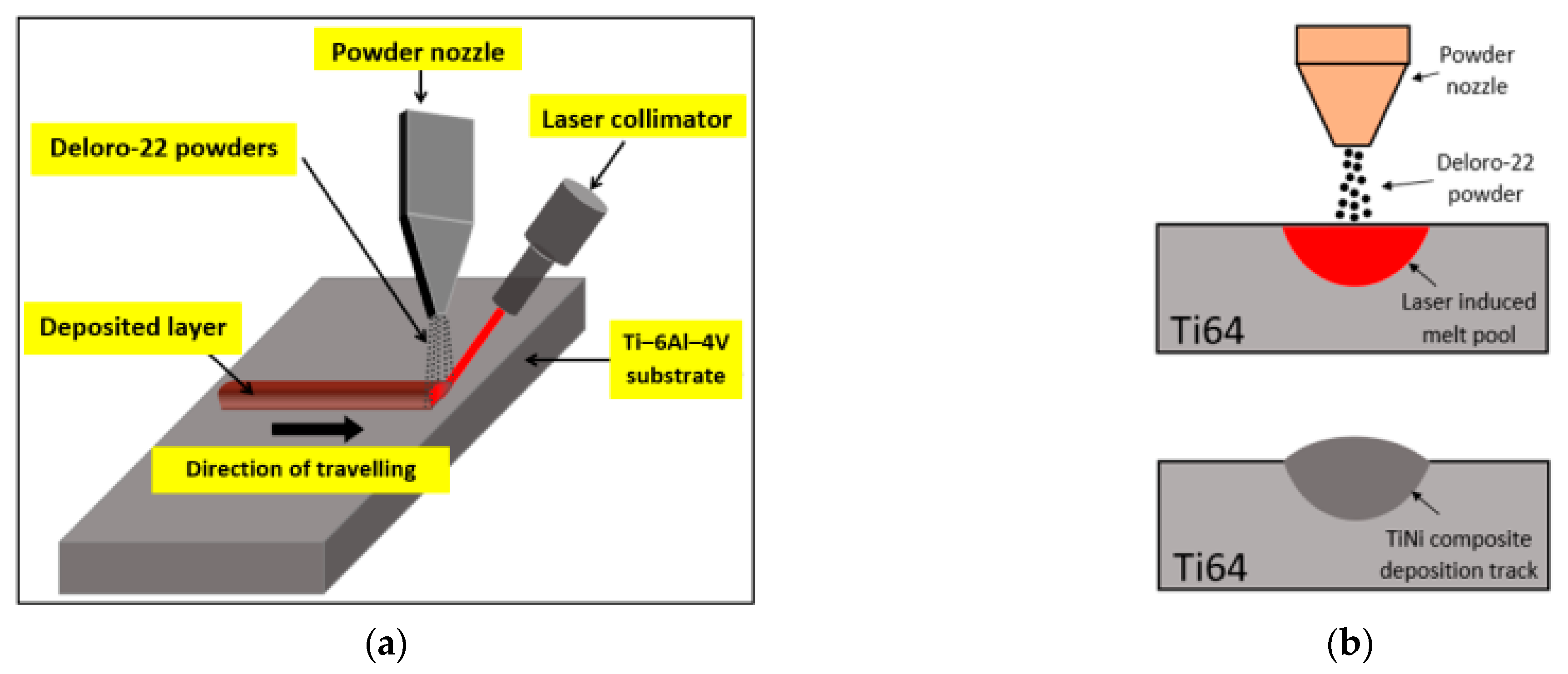
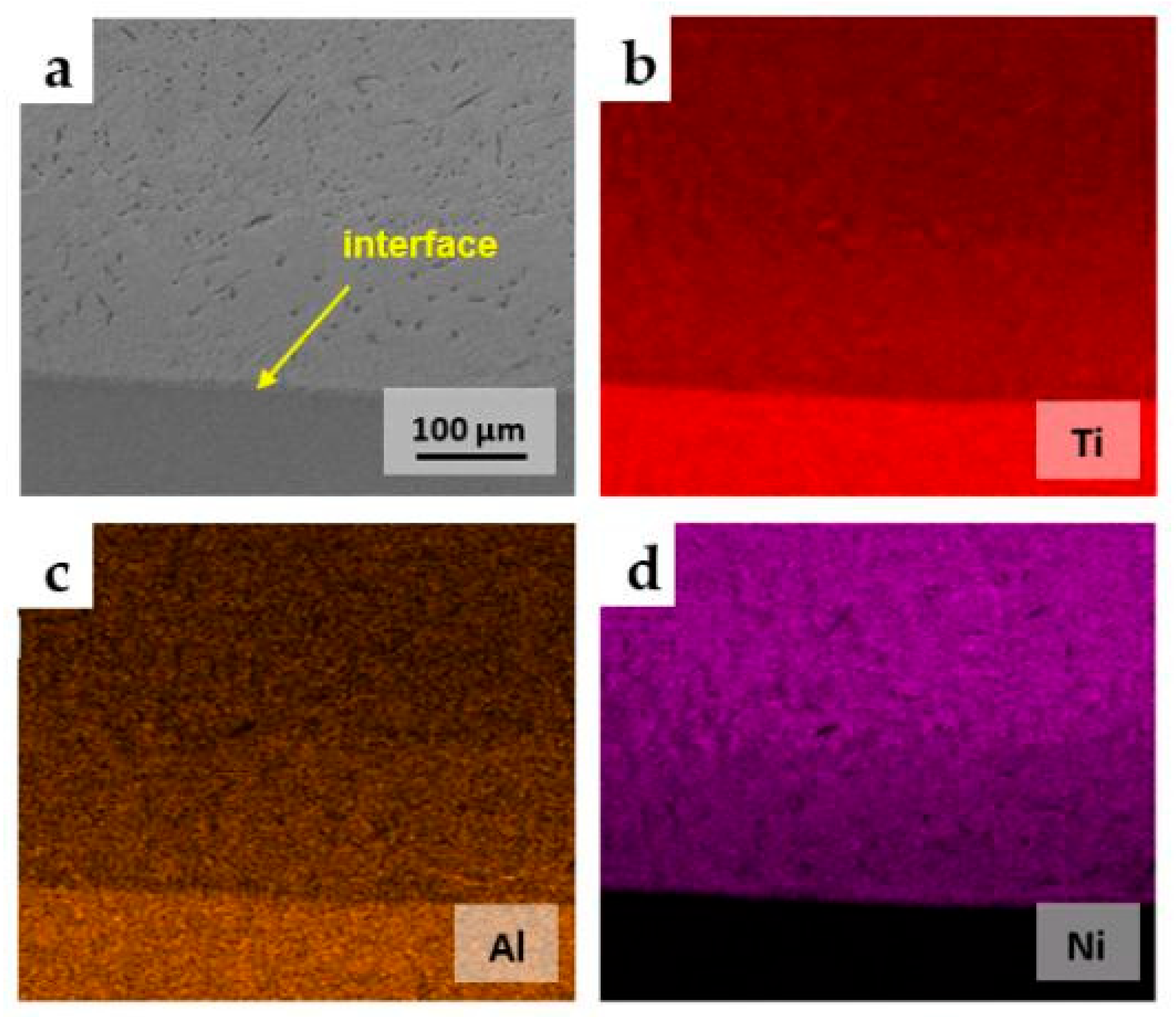
  • The laser surface deposition method with the blown powder process can be used to synthesize metals or intermetallic compounds of industrial interest in situ. In this work, the Ti-based melt pool generated using laser power can be used as the Ti source so that Ni-alloy powder feedstock can be the single type of simple and economical powder material for the formation of TixNiy intermetallics at the surface. Good bonding was seen between the deposition and the substrate, and no defects were observed.
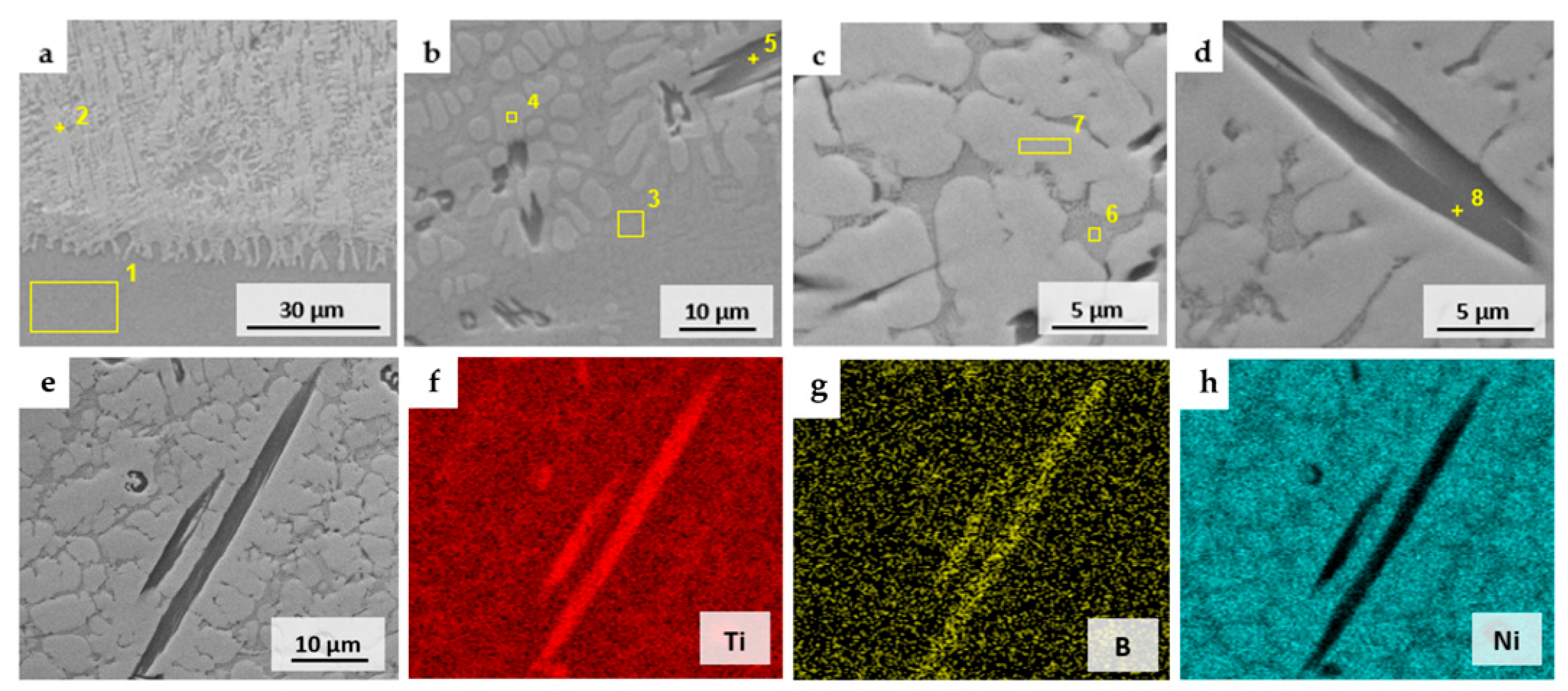
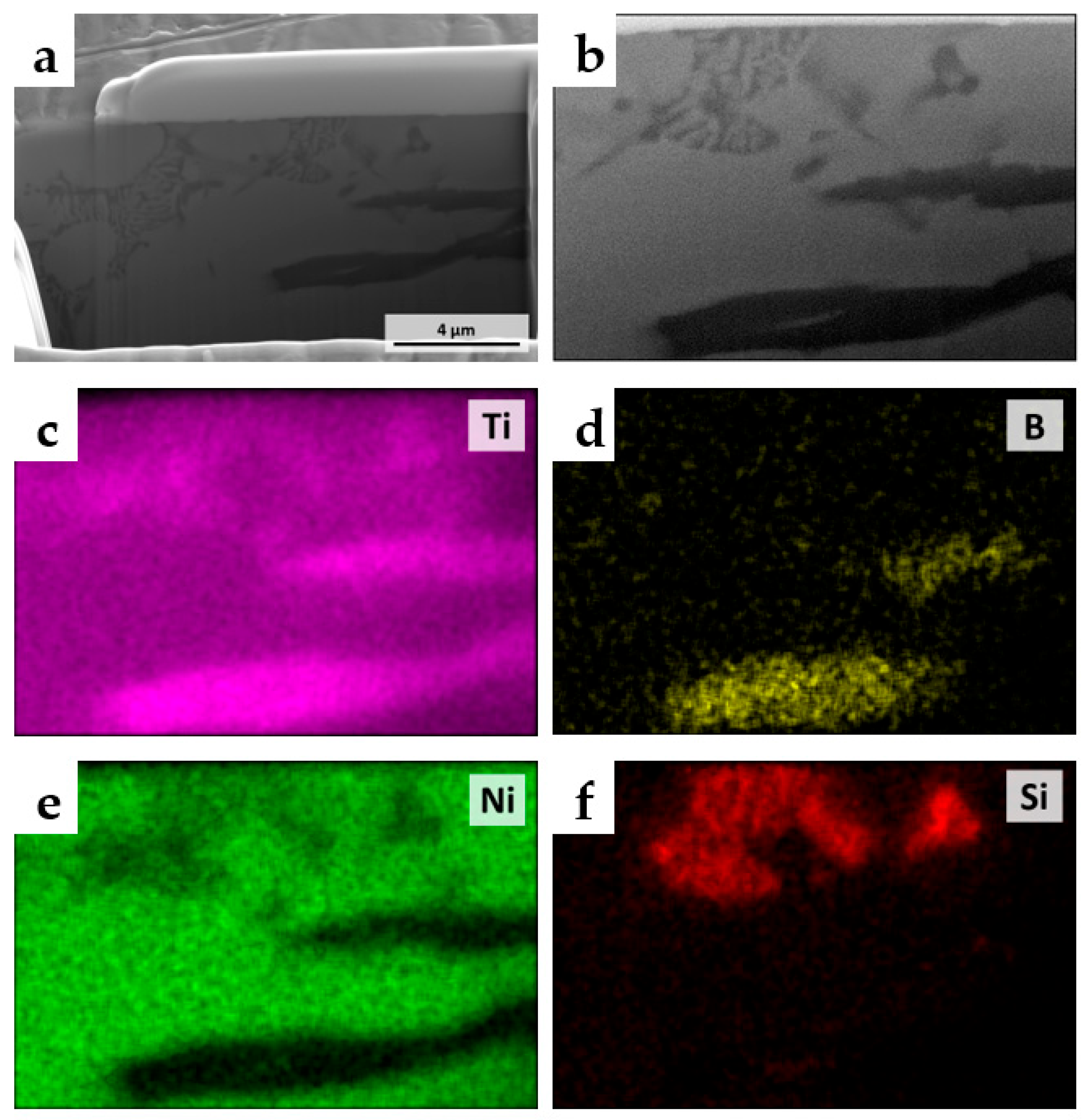
  • From SEM/EDS analysis, major phases such as TiNi and Ti2Ni and minor phases, including TiB and Ti–Ni–Si ternary phases, were observed. The energy densities from different scanning speeds resulted in differences in dilution effects, which led to multiple Ti/Ni compositions and the as-deposited phase constituents.
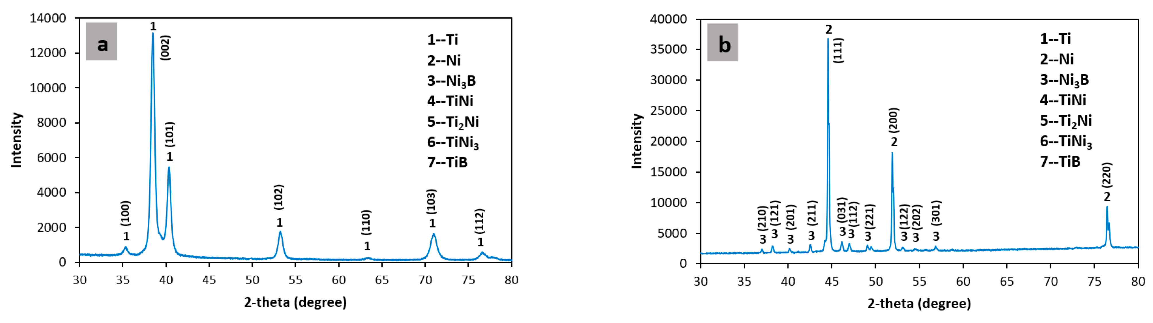
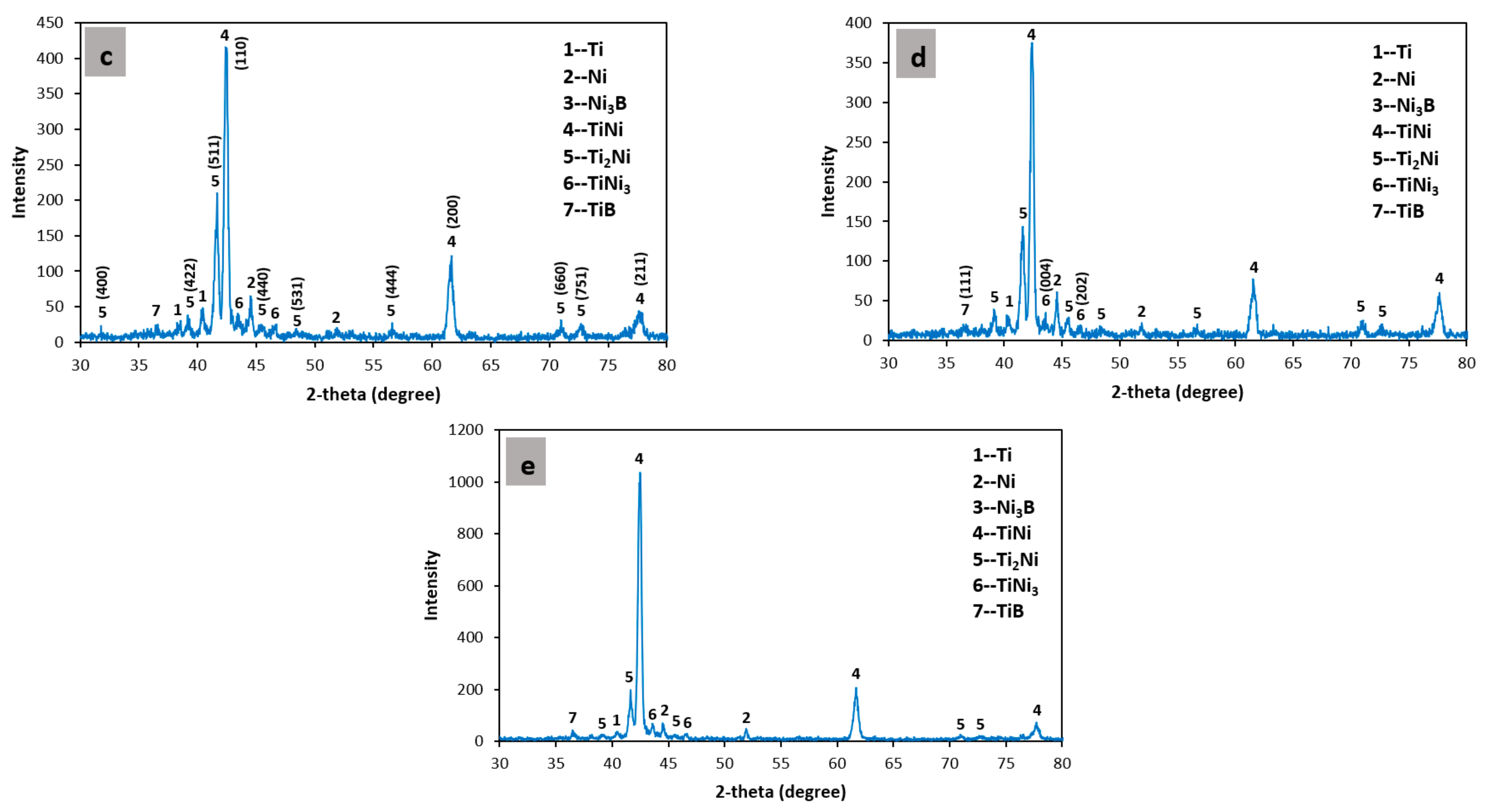
  • XRD revealed the presence of Ni3B in Deloro-22 raw powders, while TiNi and Ti2Ni were clearly detected in deposition tracks, which reflect the expected reactions to form TixNiy surface composites.
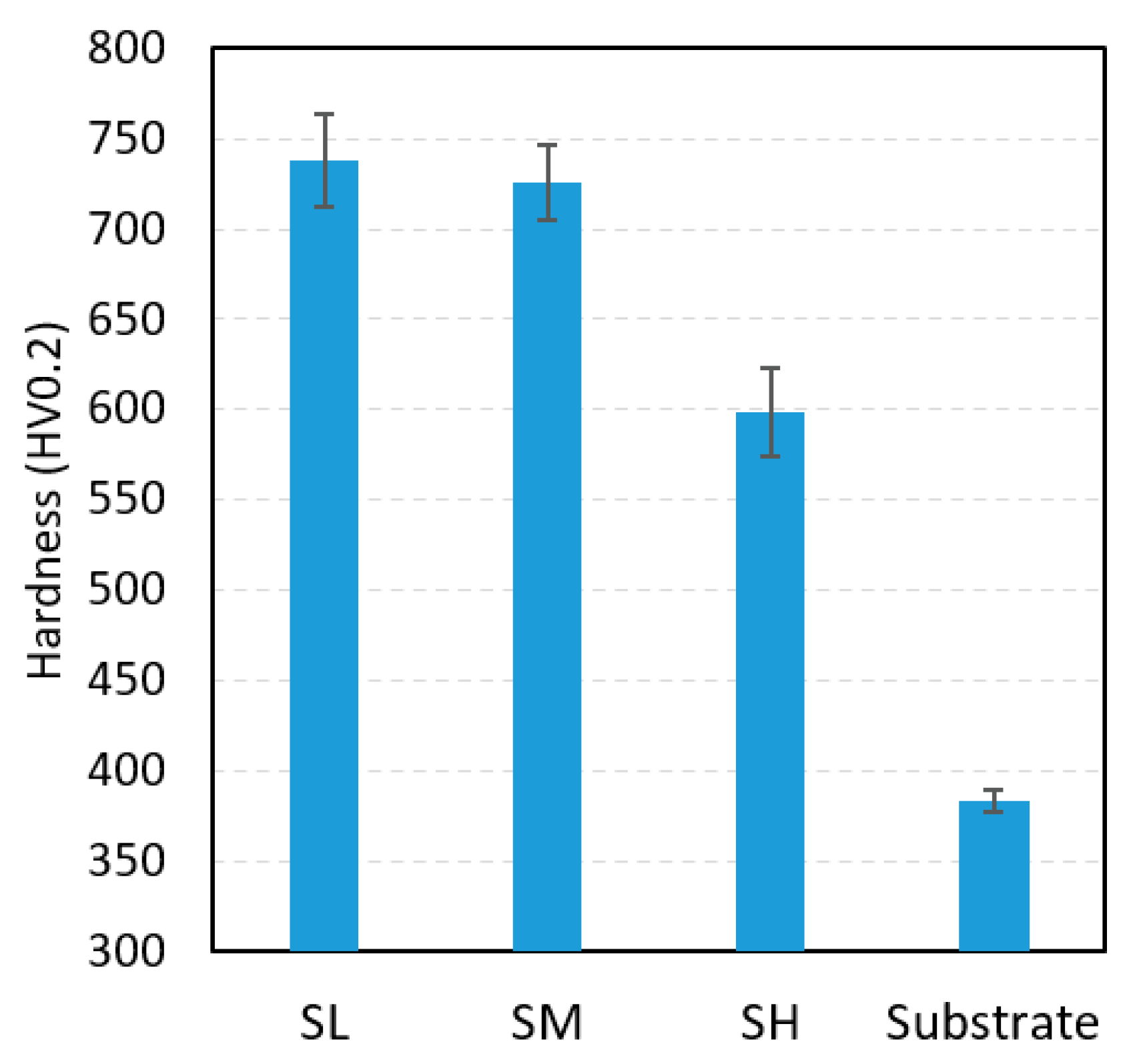
  • The slowest scanning speed obtained the highest average hardness exceeding 700 HV0.2 due to the highest energy density led to a larger amount of Ti which forms more of the Ti2Ni phase. In contrast, the highest speed resulted in more TiNi phases and an average hardness of 600 HV0.2. The hardness of the higher scan speed in this work has a relatively lower enhancement in Ti–6Al–4V hardness, while it obtained a higher crack resistance. The single type of Deloro-22 Ni-alloy powder can be used as a simpler feedstock to modify the Ti–6Al–4V surface by synthesizing various types of TixNiy via laser processing.

Author Contributions

Conceptualization, F.L.; methodology, Y.C.; formal analysis, Y.C., J.W.N.; investigation, Y.C.; writing—original draft preparation, Y.C.; writing—review and editing, Y.C., F.L.; supervision, J.W.N., F.L.; project administration, F.L.; funding acquisition, F.L. All authors have read and agreed to the published version of the manuscript.

Funding

This research was funded by the NSF Grants CMMI 1625736, NSF EEC 1937128, and Intelligent Systems Center and Material Research Center at Missouri S&T.

Institutional Review Board Statement

Not applicable.

Informed Consent Statement

Not applicable.

Data Availability Statement

Not applicable.

Acknowledgments

This research was partially funded by the NSF Grants CMMI 1625736, NSF EEC 1937128, and Intelligent Systems Center and Material Research Center at Missouri S&T. Their financial support is greatly appreciated.

Conflicts of Interest

The authors declare no conflict of interest.

References

  1. Liu, S.; Shin, Y.C. Additive manufacturing of Ti6Al4V alloy: A review. Mater. Des. 2019, 164, 107552. [Google Scholar] [CrossRef]
  2. Mironov, S.; Sato, Y.; Kokawa, H. Friction-stir welding and processing of Ti-6Al-4V titanium alloy: A review. J. Mater. Sci. Technol. 2018, 34, 58–72. [Google Scholar] [CrossRef]
  3. Dhanda, M.; Haldar, B.; Saha, P. Development and Characterization of Hard and Wear Resistant MMC Coating on Ti-6Al-4V Substrate by Laser Cladding. Procedia Mater. Sci. 2014, 6, 1226–1232. [Google Scholar] [CrossRef] [Green Version]
  4. Souza, J.C.M.; Sordi, M.B.; Kanazawa, M.; Ravindran, S.; Henriques, B.; Silva, F.S.; Aparicio, C.; Cooper, L.F. Nano-scale modification of titanium implant surfaces to enhance osseointegration. Acta Biomater. 2019, 94, 112–131. [Google Scholar] [CrossRef]
  5. Navarro, P.; Olmo, A.; Giner, M.; Rodríguez-Albelo, M.; Rodríguez, Á.; Torres, Y. Electrical Im-pedance of Surface Modified Porous Titanium Implants with Femtosecond Laser. Materials 2022, 15, 461. [Google Scholar] [CrossRef]
  6. Jamesh, M.; Narayanan, T.S.N.S.; Chu, P.K.; Park, I.S.; Lee, M.H. Effect of surface mechanical attrition treatment of titanium using alumina balls: Surface roughness, contact angle and apatite forming ability. Front. Mater. Sci. 2013, 7, 285–294. [Google Scholar] [CrossRef]
  7. Chauhan, P.; Shadangi, Y.; Bhatnagar, A.; Singh, V.; Chattopadhyay, K. Influence of Surface Nano-Structuring on Microstructure, Corrosion Behavior and Osteoblast Response of Commercially Pure Titanium Treated Through Ultrasonic Shot Peening. JOM 2022, 74, 584–595. [Google Scholar] [CrossRef]
  8. Nair, A.M.; Muvvala, G.; Sarkar, S.; Nath, A.K. Real-time detection of cooling rate using pyrometers in tandem in laser material processing and directed energy deposition. Mater. Lett. 2020, 277, 128330. [Google Scholar] [CrossRef]
  9. Chen, Y.; Lu, F.; Zhang, K.; Nie, P.; Hosseini, S.R.E.; Feng, K.; Li, Z. Dendritic microstructure and hot cracking of laser additive manufactured Inconel 718 under improved base cooling. J. Alloy. Compd. 2016, 670, 312–321. [Google Scholar] [CrossRef]
  10. Ding, Y.; Du, C.; Wang, X.; Zhang, B. Microstructure and interfacial metallurgical bonding of 1Cr17Ni2/carbon steel extreme high-speed laser cladding coating. Adv. Compos. Hybrid Mater. 2021, 4.1, 205–211. [Google Scholar] [CrossRef]
  11. Majumdar, J.D.; Manna, I.; Kumar, A.; Bhargava, P.; Nath, A.K. Direct laser cladding of Co on Ti–6Al–4V with a compositionally graded interface. J. Mater. Process. Technol. 2009, 209, 2237–2243. [Google Scholar] [CrossRef]
  12. Farotade, G.A.; Adesina, O.S.; Popoola AP, I.; Pityana, S.L. Laser Cladding and Characteri-zation of Ni–SiC–ZrB2 Cermet Coatings on Ti–6Al–4V for High-Temperature Applications. Metallogr. Microstruct. Anal. 2019, 8, 349–358. [Google Scholar] [CrossRef]
  13. Li, J.; Chen, C.; Squartini, T.; He, Q. A study on wear resistance and microcrack of the Ti3Al/TiAl+ TiC ceramic layer deposited by laser cladding on Ti–6Al–4V alloy. Appl. Surf. Sci. 2010, 257, 1550–1555. [Google Scholar] [CrossRef]
  14. Jiang, T.; Kim, H.S. Simultaneous improvement in the hardness and friction characteristics of Ti-6Al-4V through laser cladding with nanoscale SiC particles in an air environment. Int. J. Adv. Manuf. Technol. 2021, 116, 1041–1051. [Google Scholar] [CrossRef]
  15. Wang, J.; Pan, Z.; Wang, L.; Su, L.; Carpenter, K.; Wang, J.; Wang, R.; Li, H. In-situ dual wire arc additive manufacturing of NiTi-coating on Ti6Al4V alloys: Microstructure characterization and mechanical properties. Surf. Coat. Technol. 2020, 386, 125439. [Google Scholar] [CrossRef]
  16. Jia, C.; Xiong, Z.P.; Liu, Z.; Cheng, X. Structural designation and mechanical properties of TiNi/Ti2Ni laminated composites. J. Phys. Conf. Ser. 2020, 1507, 062010. [Google Scholar] [CrossRef]
  17. Lin, Y.; Lei, Y.; Fu, H.; Lin, J. Mechanical properties and toughening mechanism of TiB2/NiTi reinforced titanium matrix composite coating by laser cladding. Mater. Des. 2015, 80, 82–88. [Google Scholar] [CrossRef]
  18. Su, W.; Cui, X.; Yang, Y.; Guan, Y.; Zhao, Y.; Wan, S.; Li, J.; Jin, G. Effect of Si content on micro-structure and tribological properties of Ti5Si3/TiC reinforced NiTi laser cladding coatings. Surf. Coat. Technol. 2021, 418, 127281. [Google Scholar] [CrossRef]
  19. Zhang, X.; Cui, W.; Li, W.; Liou, F. Effects of tool path in remanufacturing cylindrical components by laser metal deposition. Int. J. Adv. Manuf. Technol. 2019, 100, 1607–1617. [Google Scholar] [CrossRef]
  20. Mokgalaka, M.N.; Pityana, S.L.; Popoola PA, I.; Mathebula, T. NiTi interme-tallic surface coatings by laser metal deposition for improving wear properties of Ti-6Al-4V substrates. Adv. Mater. Sci. Eng. 2014, 2014, 363917. [Google Scholar] [CrossRef] [Green Version]
  21. Mokgalaka, M.N.; Popoola AP, I.; Pityana, S.L. In situ laser deposition of NiTi intermetallics for corrosion improvement of Ti–6Al–4V alloy. Trans. Nonferrous Met. Soc. China 2015, 25, 3315–3322. [Google Scholar] [CrossRef]
  22. Liu, F.; Mao, Y.; Lin, X.; Zhou, B.; Qian, T. Microstructure and high temperature oxidation resistance of Ti-Ni gradient coating on TA2 titanium alloy fabricated by laser cladding. Opt. Laser Technol. 2016, 83, 140–147. [Google Scholar] [CrossRef]
  23. Aich, S.; Chandran, K.S.R. TiB whisker coating on titanium surfaces by solid-state diffusion: Synthesis, microstructure, and mechanical properties. Met. Mater. Trans. A 2002, 33, 3489–3498. [Google Scholar] [CrossRef]
  24. Song, R.; Li, J.; Shao, J.; Bai, L.; Chen, J.; Qu, C. Microstructural evolution and wear behaviors of laser cladding Ti 2 Ni/α(Ti) dual-phase coating reinforced by TiB and TiC. Appl. Surf. Sci. 2015, 355, 298–309. [Google Scholar] [CrossRef]
  25. Karnati, S.; Zhang, Y.; Liou, F.F.; Newkirk, J.W. On the Feasibility of Tailoring Copper–Nickel Functionally Graded Materials Fabricated through Laser Metal Deposition. Metals 2019, 9, 287. [Google Scholar] [CrossRef] [Green Version]
  26. Gorsse, S.; Le Petitcorps, Y.; Matar, S.; Rebillat, F. Investigation of the Young’s modulus of TiB needles in situ produced in titanium matrix composite. Mater. Sci. Eng. A 2003, 340, 80–87. [Google Scholar] [CrossRef]
  27. Cheng, Y.Y. Synthesis of Metal Boride Nanoparticles by RF Thermal Plasmas. Ph.D. Thesis, Tokyo Institute of Technology, Tokyo, Japan, 2014. [Google Scholar]
  28. Wang, C.; Tan, X.; Du, Z.; Chandra, S.; Sun, Z.; Lim, C.; Tor, S.; Wong, C. Additive manufacturing of NiTi shape memory alloys using pre-mixed powders. J. Mater. Process. Technol. 2019, 271, 152–161. [Google Scholar] [CrossRef]
  29. Ren, H.S.; Xiong, H.P.; Pang, S.J.; Chen, B.; Wu, X.; Cheng, Y.Y.; Chen, B.Q. Microstructures and Mechanical Properties of Transient Liquid-Phase Diffusion-Bonded Ti3Al/TiAl Joints with TiZrCuNi Interlayer. Met. Mater. Trans. A 2016, 47, 1668–1676. [Google Scholar] [CrossRef]
  30. Chen, Y.; Zhang, X.; Parvez, M.M.; Newkirk, J.W.; Liou, F. Fabricating TiNiCu Ternary Shape Memory Alloy by Directed Energy Deposition via Elemental Metal Powders. Appl. Sci. 2021, 11, 4863. [Google Scholar] [CrossRef]
  31. Lin, P.-Y.; Shen, F.-C.; Wu, K.-T.; Hwang, S.-J.; Lee, H.-H. Process optimization for directed energy deposition of SS316L components. Int. J. Adv. Manuf. Technol. 2020, 111, 1387–1400. [Google Scholar] [CrossRef]
  32. Liu, Y.; Yang, L.; Yang, X.; Zhang, T.; Sun, R. Optimization of microstructure and properties of com-posite coatings by laser cladding on titanium alloy. Ceram. Int. 2021, 47, 2230–2243. [Google Scholar] [CrossRef]
  33. Li, W.; Zhang, J.; Karnati, S.; Zhang, Y.; Liou, F.W.; Newkirk, J.W.; Seufzer, W.L.; Taminger, K.M.B.; Seufzer, W.L. Modeling and Experimental Investigation of Pre-Mixed Multi-Powder Flow in Fabricating Functional Gradient Material by Laser Metal Deposition Process; University of Texas at Austin: Austin, TX, USA, 2016. [Google Scholar]
Figure 1. A schematic illustration of fabricating Ti–Ni alloys on a Ti–6Al–4V substrate. (a) The overall view. (b) The cross-sectional view.
Metals 13 00243 g001
Figure 2. (a) SEM image of Deloro-22 powders. (b) Deloro-22 powder particle size distribution.
Metals 13 00243 g002
Figure 3. Microstructural features at the interface: (a) SL, (b) SM, (c) SH. Microstructural features in the upper region: (d) SL, (e) SM, (f) SH.
Metals 13 00243 g003
Figure 4. (a) EDS analysis at the interface of the deposition track. (b) EDS analysis in the region slightly above the interface. (c,d) EDS analysis in the upper region of Sample SH. (e) Electron image of region of Sample SH for EDS mapping. (fh) EDS mapping of Ti, B, and Ni based on the electron image in (e). Numbers 1~8 indicate the selected points/areas for EDS.
Metals 13 00243 g004
Figure 5. (a) SEM image of the FIB cross-section. (b) Higher magnification of the area from (a) for element mapping. (c) Element mapping of Ti. (d) Element mapping of B. (e) Element mapping of Ni. (f) Element mapping of Si.
Metals 13 00243 g005
Figure 6. EDS element mapping of the interfacial region in Sample SH. (a) Electron image of the interfacial region of SH. (b) Element mapping of Ti. (c) Element mapping of Al. (d) Element mapping of Ni.
Metals 13 00243 g006
Figure 7. XRD results of (a) Ti–6Al–4V. (b) Deloro-22 powders. (ce) Sample SL, SM, and SH, respectively.
Metals 13 00243 g007aMetals 13 00243 g007b
Figure 8. The hardness level of SL, SM, SH, and substrate.
Metals 13 00243 g008
Figure 9. The 2 kgf indentation marks on (a) SL and (b) SH. It can be seen that the deposition of SL demonstrates higher hardness and longer indentation cracks.
Metals 13 00243 g009
Table 1. Chemical composition of Deloro-22 powders (wt.%).
NiSiBFeC
Balance2.51.41.00.05
Table 2. EDS results of the eight points/areas (at.%).
No. of
Points/Areas
TiNiSiAlVFeB
185.230.140.0511.153.280.15-
261.2228.480.717.471.800.32-
357.4428.702.788.052.800.22-
446.6045.760.565.850.830.40-
544.623.700.100.244.020.0647.27
646.3837.848.654.502.360.27-
744.7044.222.935.792.040.32-
843.331.610.250.114.770.0649.86
Disclaimer/Publisher’s Note: The statements, opinions and data contained in all publications are solely those of the individual author(s) and contributor(s) and not of MDPI and/or the editor(s). MDPI and/or the editor(s) disclaim responsibility for any injury to people or property resulting from any ideas, methods, instructions or products referred to in the content.

