Comparison of Different Manufacturing Processes of AISI 4140 Steel with Regard to Surface Modification and Its Influencing Depth

 , , , ,
Abstract
:1. Introduction
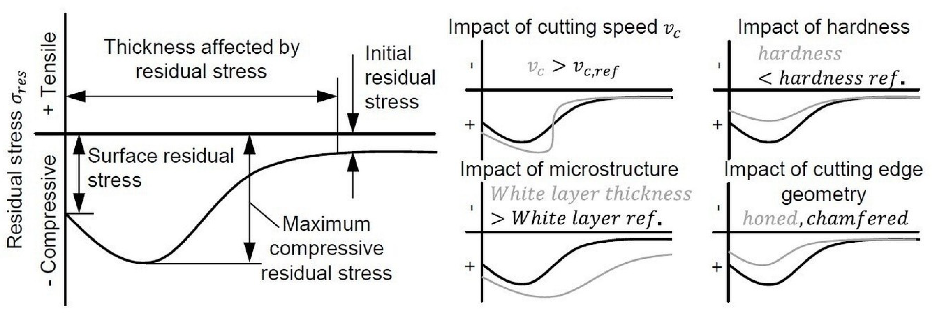
1.1. Surface Integrity
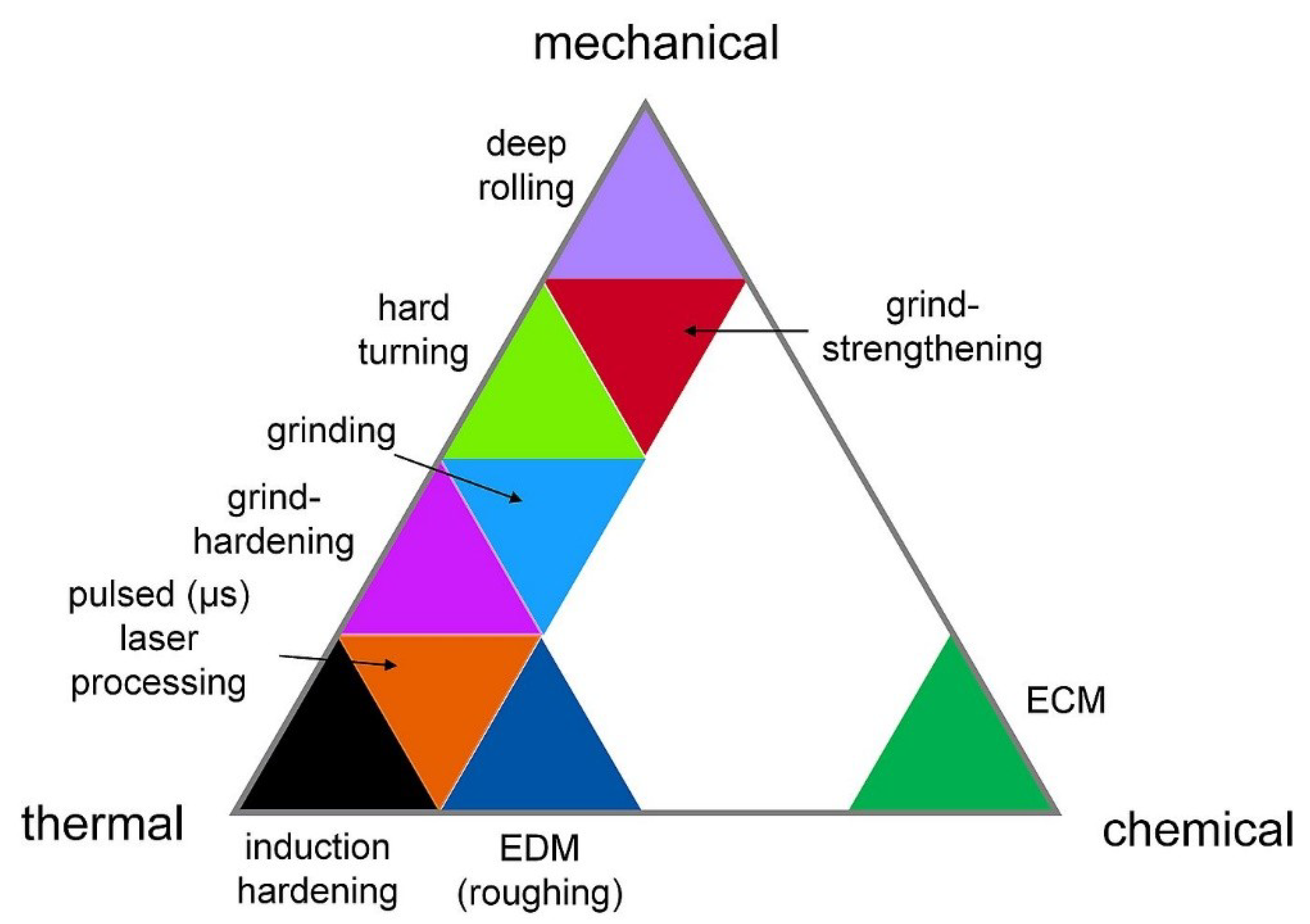
1.2. Process Fundamentals on Machining Operations
1.2.1. Deep Rolling
1.2.2. Grinding
1.2.3. Grind Strengthening
1.2.4. Grind Hardening
1.2.5. Hard Turning
1.2.6. Induction Hardening
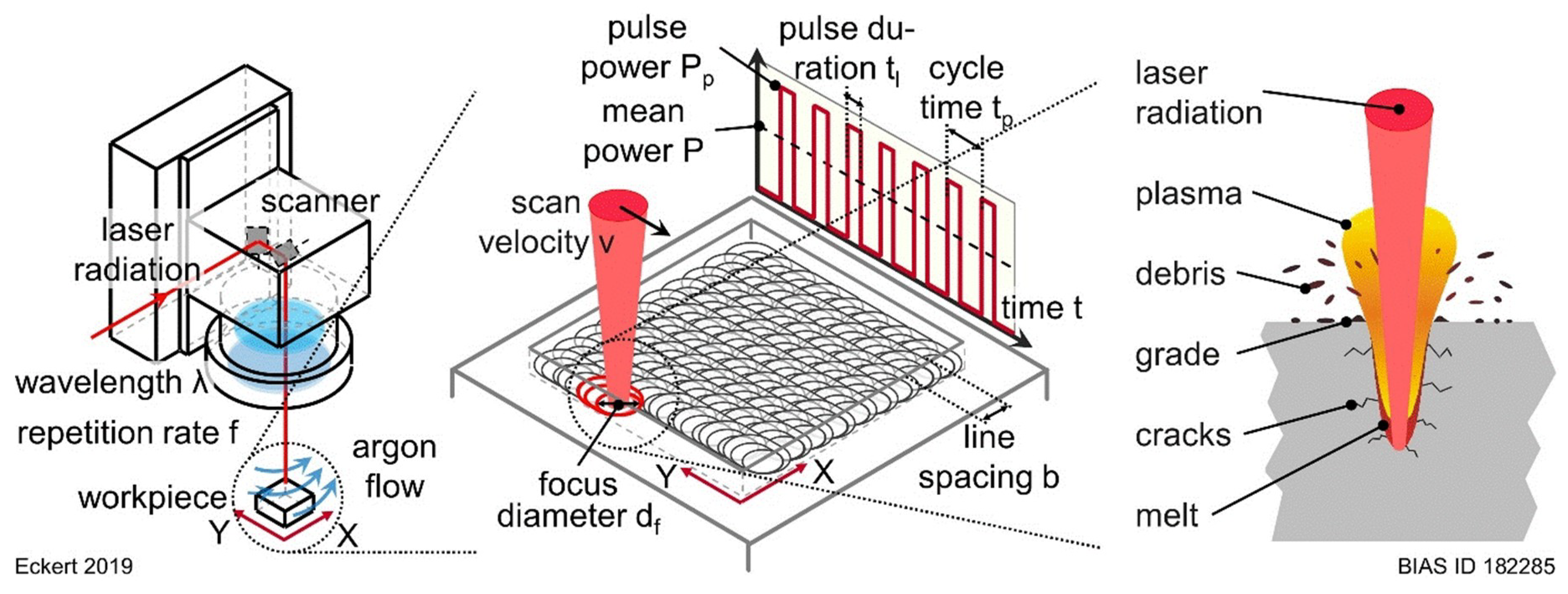
1.2.7. Pulsed (µs) Laser Processing
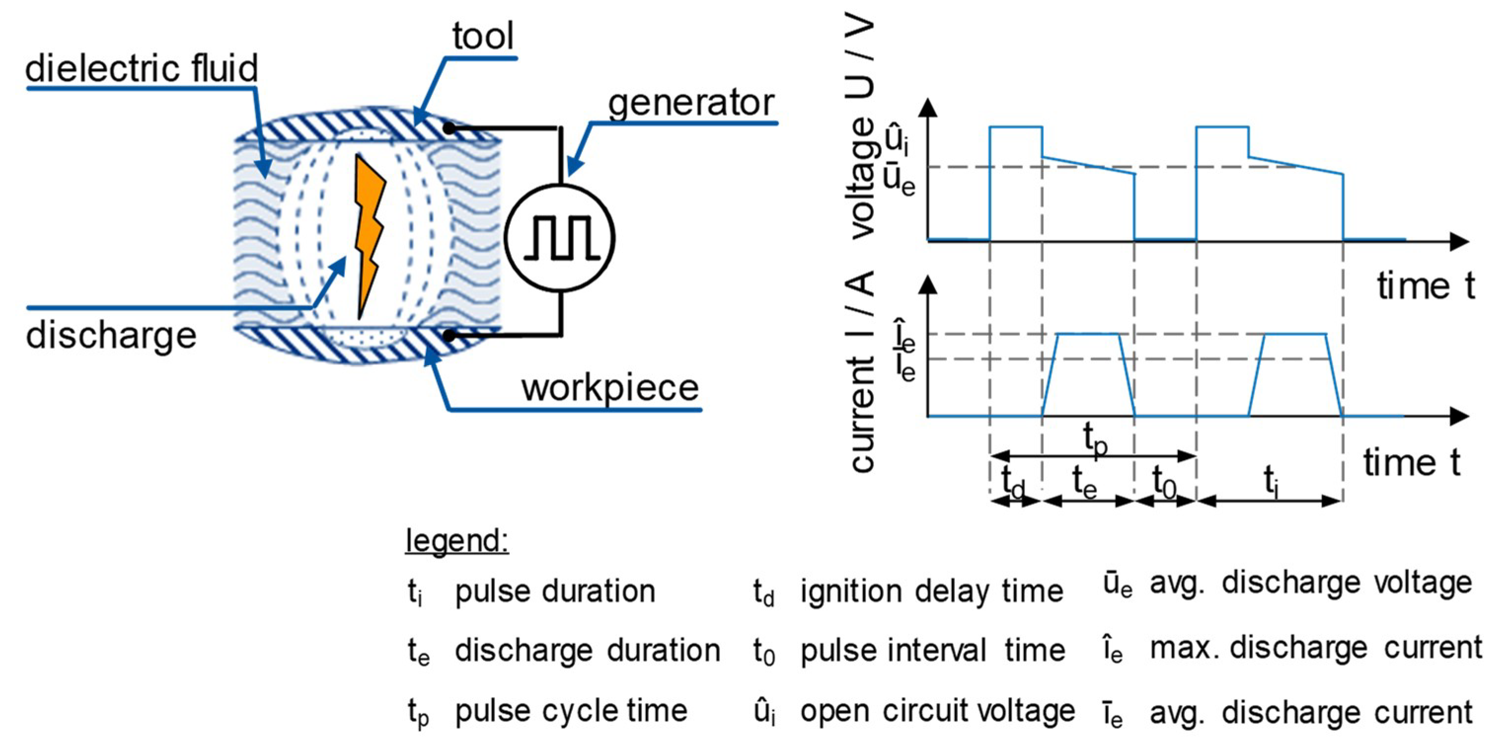
1.2.8. Electrical Discharge Machining
1.2.9. Electrochemical Machining
2. Materials and Methods
2.1. Uniform Starting Position
2.2. Machining Operations
2.2.1. Deep Rolling
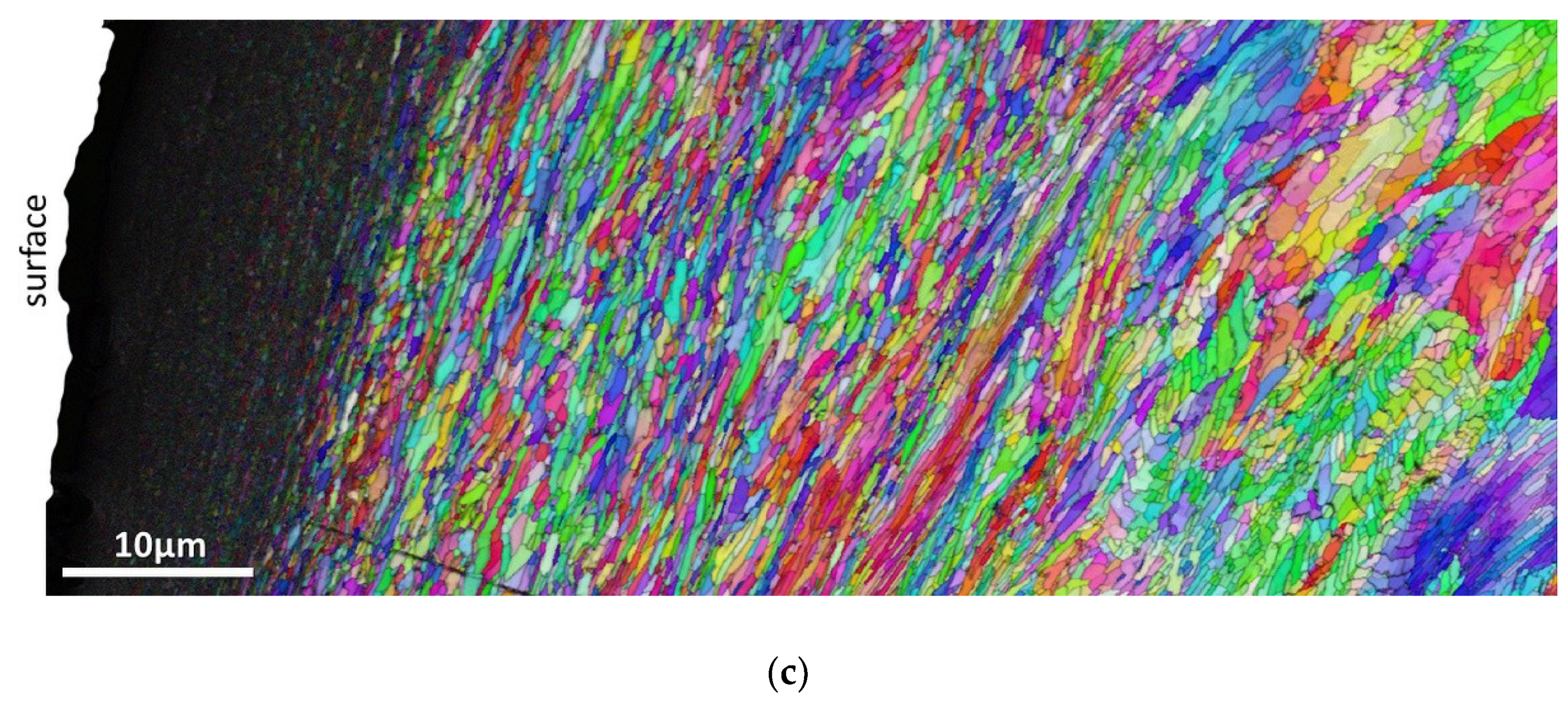
2.2.2. Grind Strengthening
2.2.3. Grind Hardening
2.2.4. Hard Turning
2.2.5. Induction Hardening
2.2.6. Pulsed (µs) Laser Processing
2.2.7. EDM
2.2.8. ECM
2.3. Analysing Techniques
2.3.1. Hardness Measurement
2.3.2. Scanning Electron Microscopy (SEM), Energy-Dispersive X-ray Spectroscopy (EDS) and Electron Backscatter Diffraction (EBSD) Measurements
2.3.3. X-ray-Diffraction
3. Results
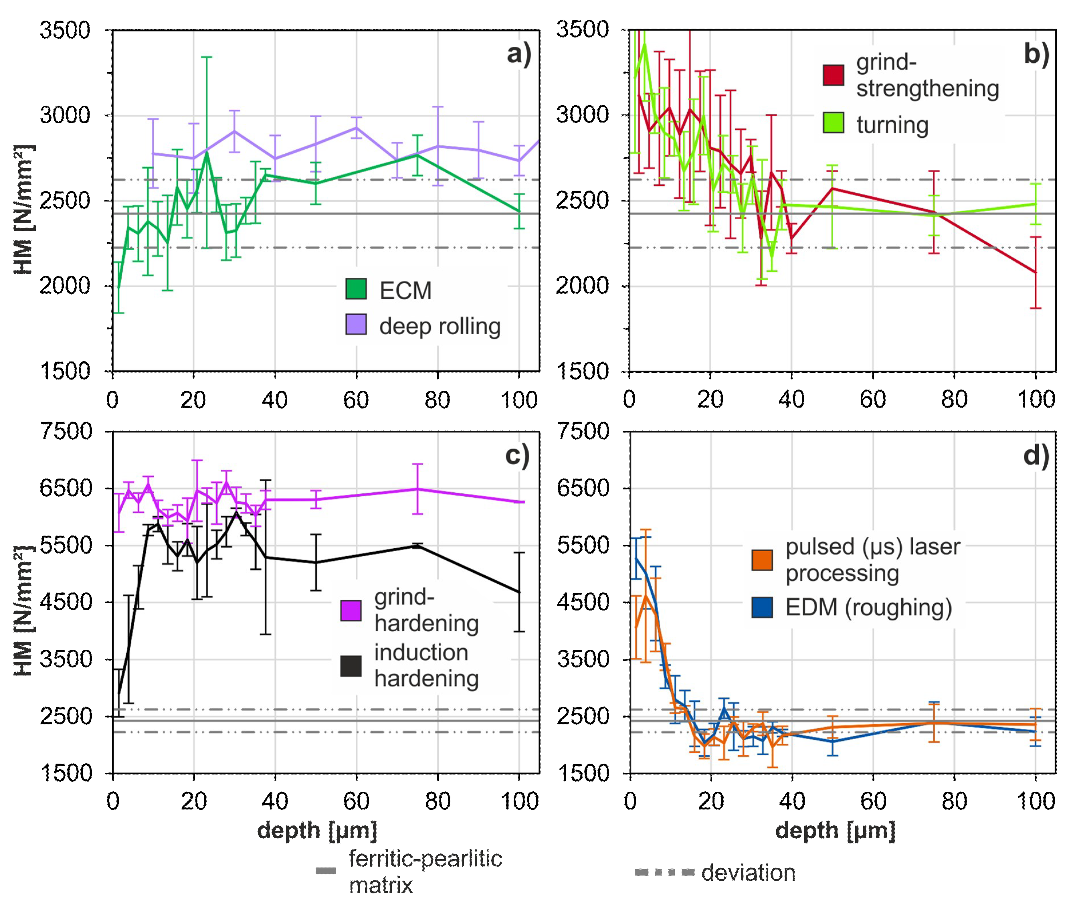
3.1. Comparison of Hardness Measurement Investigation Results
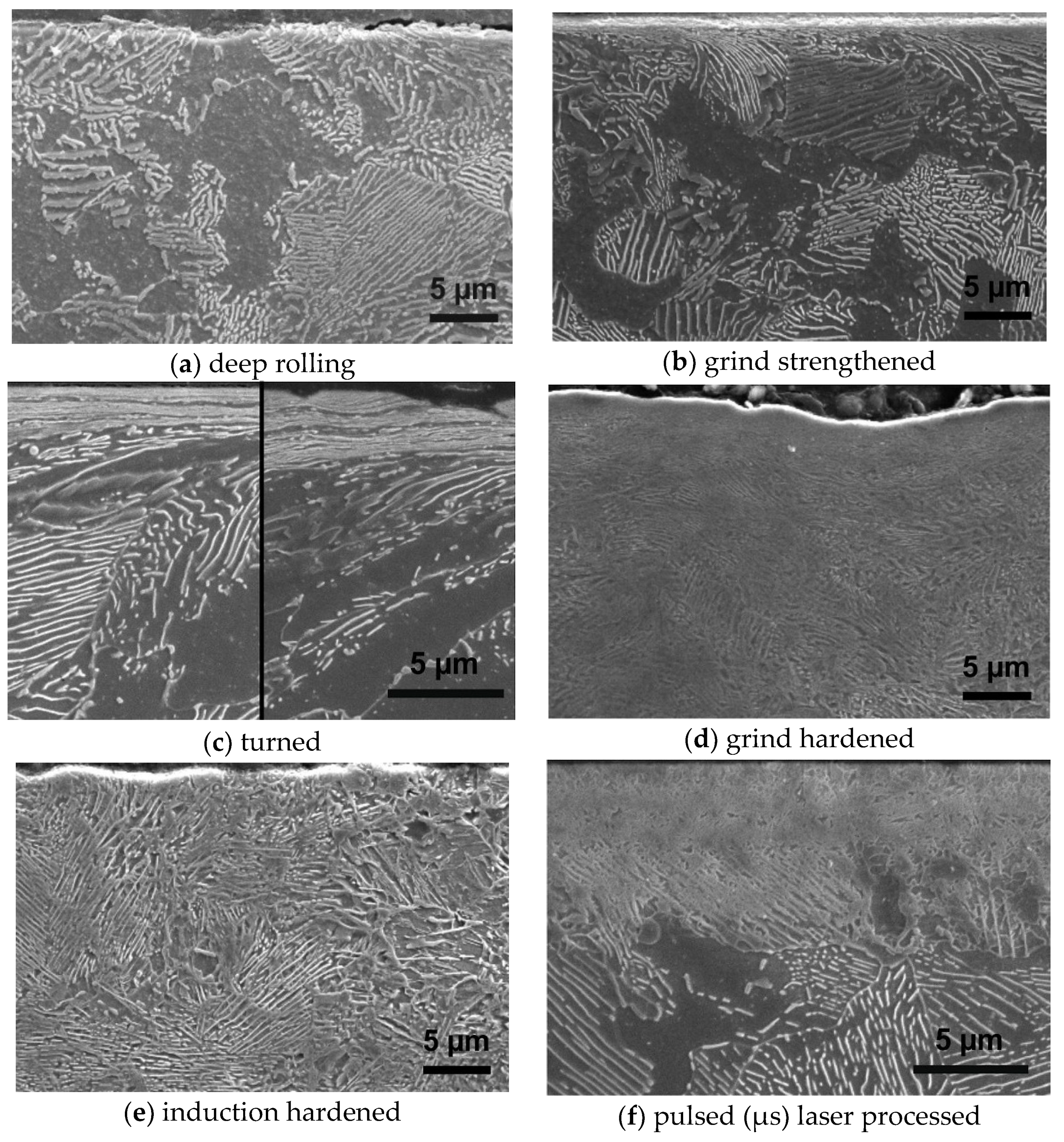
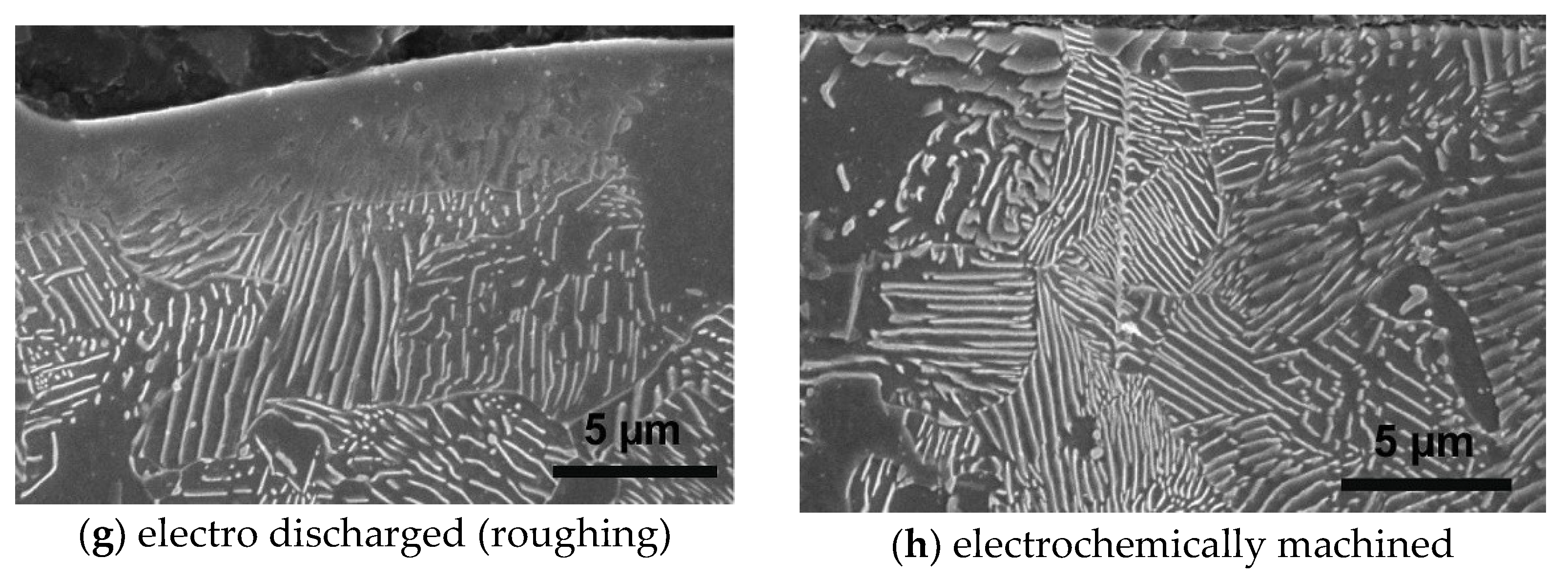
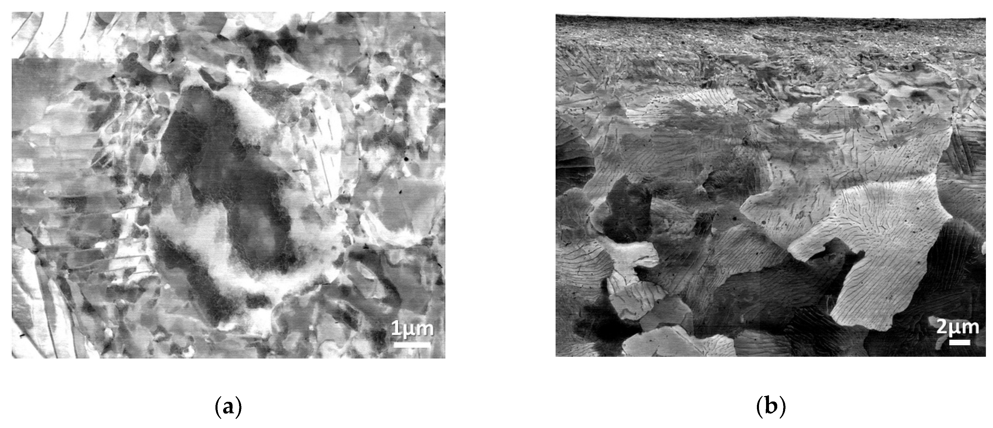
3.2. Comparison of Electron Microscope Results
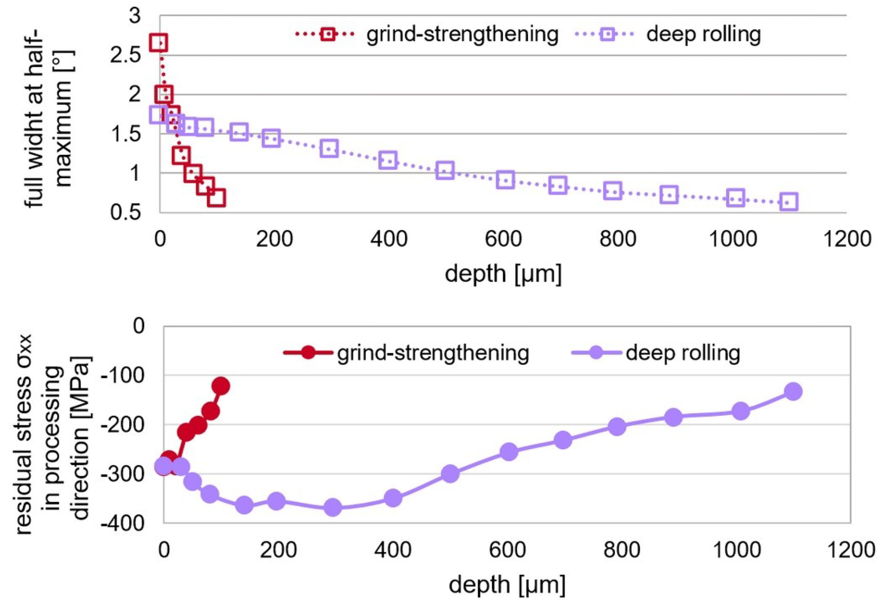
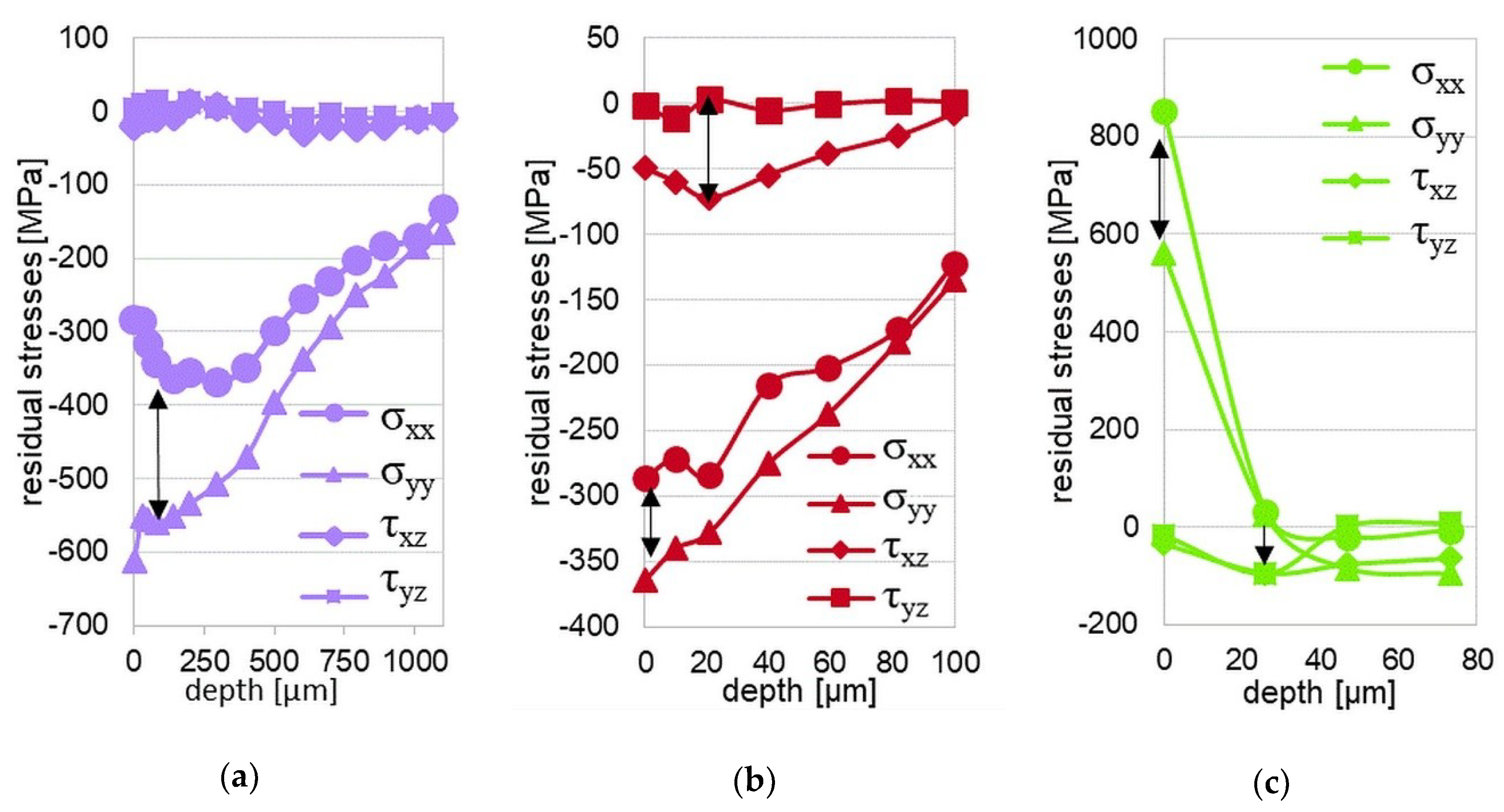
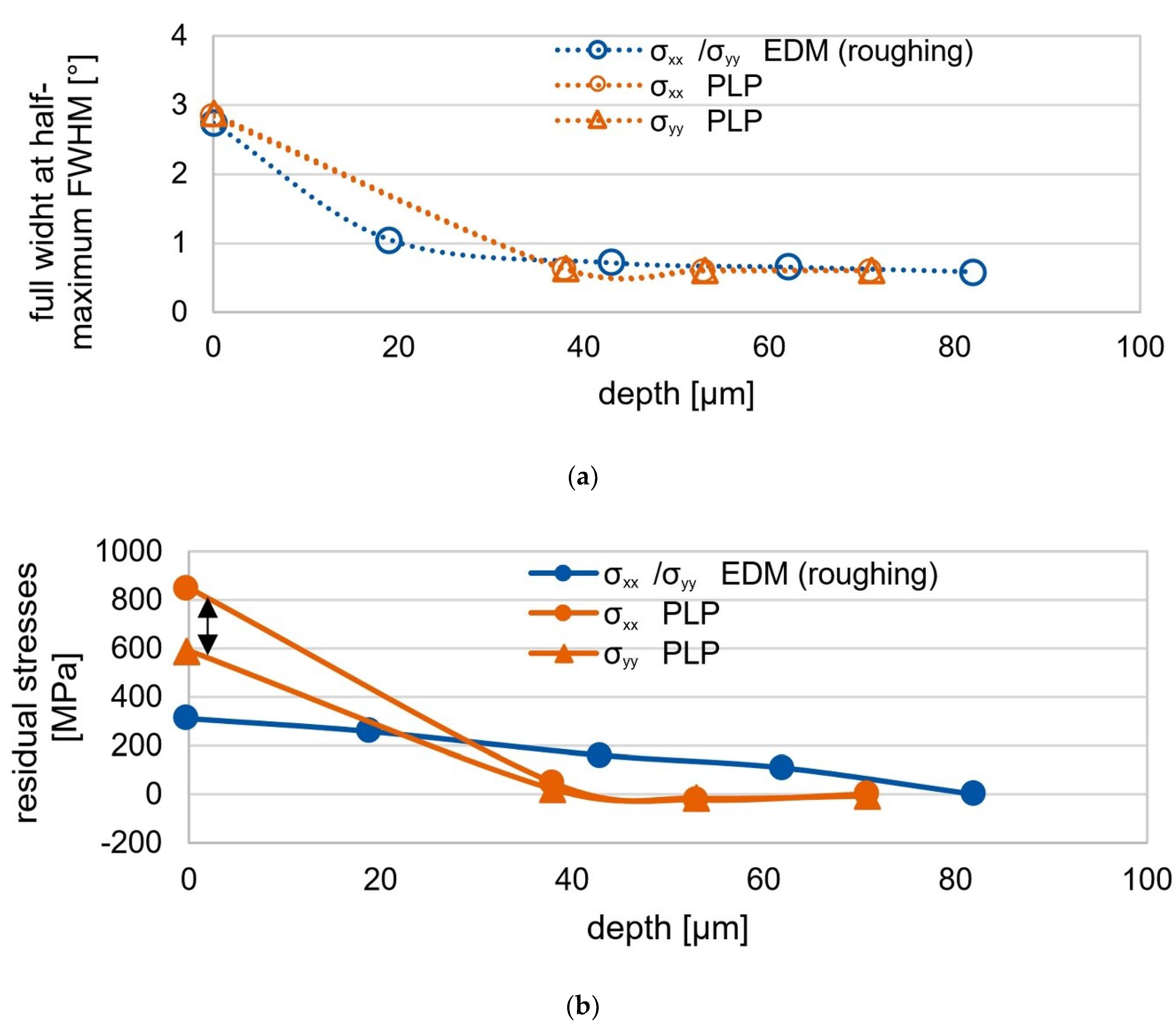
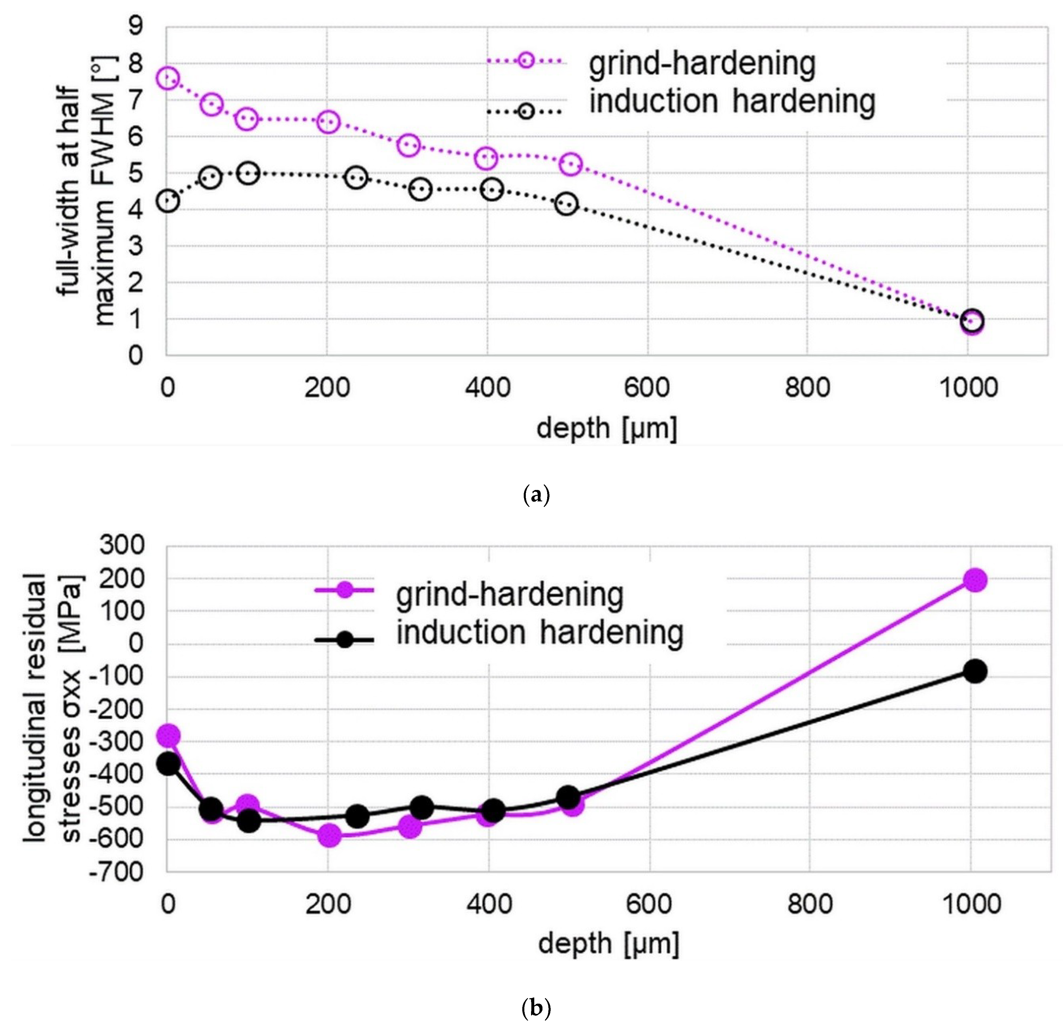
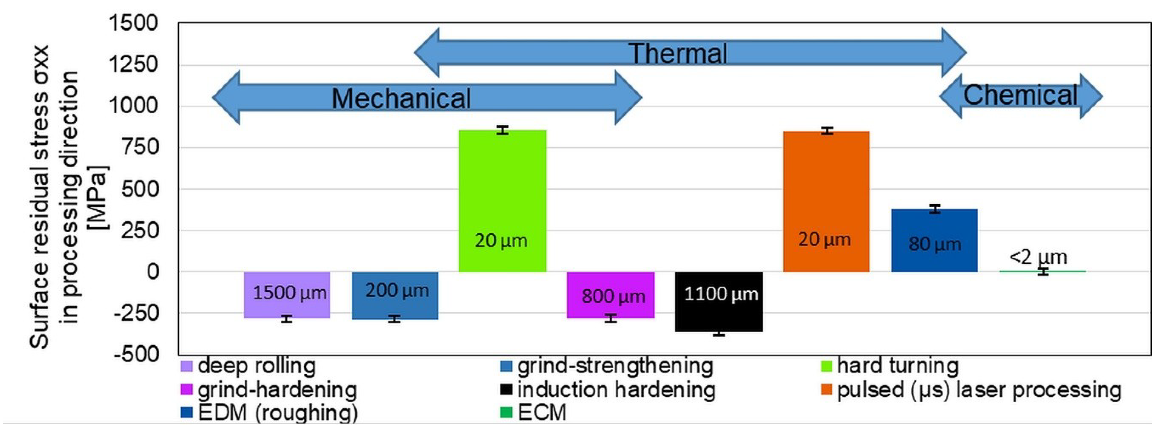
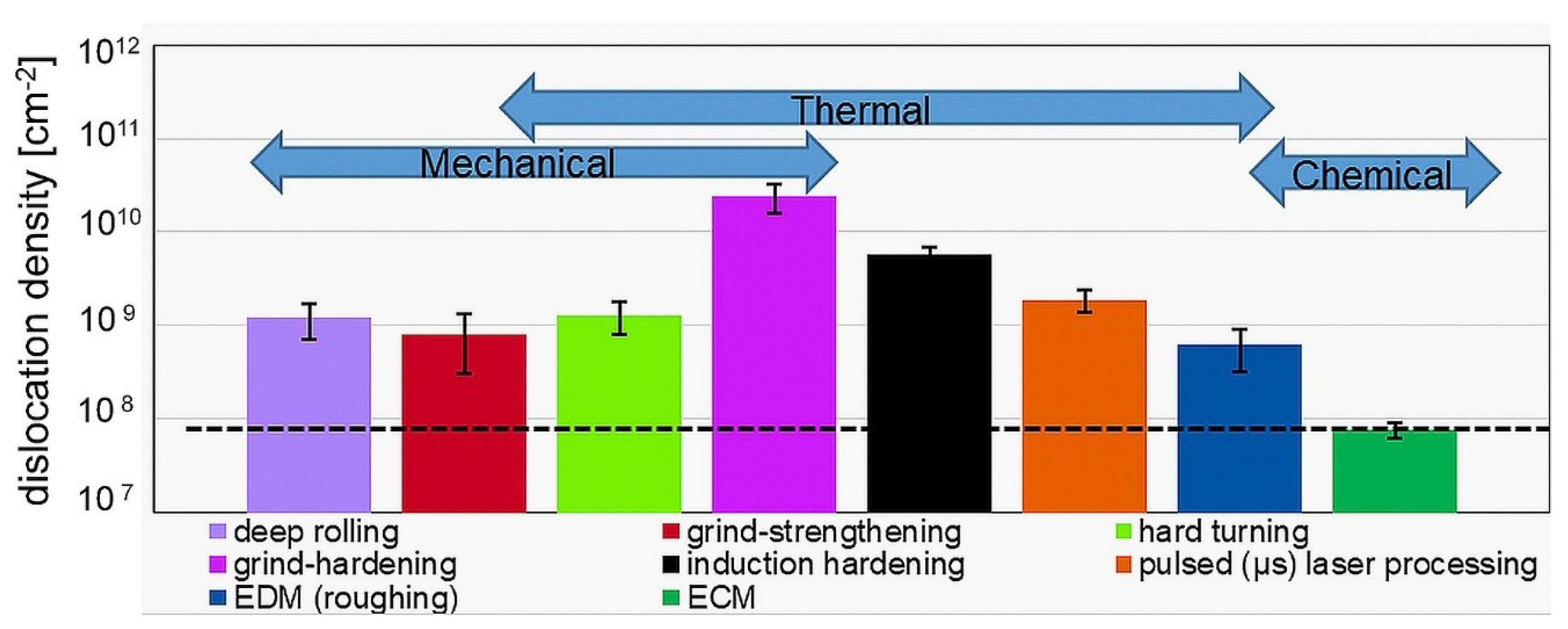
3.3. Evaluation of X-ray Diffraction Measurements
4. Discussion
5. Conclusions
Author Contributions
Funding
Acknowledgments
Conflicts of Interest
References
- Jawahir, I.S.; Brinksmeier, E.; M’Saoubi, R.; Aspinwall, D.K.; Outeiro, J.C.; Meyer, D.; Umbrello, D.; Jayal, A.D. Surface integrity in material removal processes: Recent advances. CIRP Annals Manuf. Technol. 2011, 60, 603–626. [Google Scholar] [CrossRef]
- Field, M.; Koster, W. Optimizing grinding parameters to combine high productivity with high surface integrity. CIRP Ann Manuf. Technol. 1978, 27, 523–526. [Google Scholar]
- Gerstenmeyer, M.; Hartmann, J.; Zanger, F.; Schulze, V. Adjustment of Lifetime-Increasing Surface Layer States by Complematary Machining. HTM J. Heat Treat. Mater. 2019, 74, 181–190. [Google Scholar] [CrossRef]
- Brinksmeier, E.; Meyer, D.; Heinzel, C.; Lübben, T.; Sölter, J.; Langenhorst, L.; Frerichs, F.; Kämmler, J.; Kohls, E.; Kuschel, S. Process Signatures—The Missing Link to Predict Surface Integrity in Machining. Proc. CIRP 2018, 71, 3–10. [Google Scholar] [CrossRef]
- Speidel, A.; Mitchell-Smith, J.; Bisterov, I.; Clare, A.T. The importance of microstructure in electrochemical jet processing. J. Mater. Proc. Technol. 2018, 262, 459–470. [Google Scholar] [CrossRef]
- Speidel, A.; Mitchell-Smith, J.; Bisterov, I.; Clare, A.T. The dependence of sur-face finish on material precondition in EC jet machining. Procedia CIRP 2018, 68, 477–482. [Google Scholar] [CrossRef]
- Maradia, U.; Filisetti, E.; Boccadoro, M.; Roten, M.; Dutoit, J.-M.; Hengsberger, S. Increasing the injection moulding productivity through EDM surface modulation. Proc. CIRP 2018, 68, 58–63. [Google Scholar] [CrossRef]
- Berstein, G.; Fuchbauer, B. Festwalzen und Schwingfestigkeit. Materialwiss. Werkst. 1982, 13, 103–109. [Google Scholar] [CrossRef]
- Kocke, F.; Liermann, J. Roller burnishing of hard turned surfaces. Int. J. Mach. Tools Manuf. 1998, 38, 419–423. [Google Scholar] [CrossRef]
- Röttger, K.; Wilcke, G.; Mader, S. Festwalzen—Eine Technologie für effizienten Leichtbau. Mater. Werkst. Entwickl. Fert. Prüf. Eigenschaften Anwend. Tech. Werkst. 2005, 36, 270–274. [Google Scholar] [CrossRef]
- Röttger, K. Walzen Hartgedrehter Oberflächen. Ph.D. Dissertation, RWTH Aachen University, Aachen, Germany, 2003. [Google Scholar]
- Lauwers, B.; Klocke, F.; Klink, A.; Tekkaya, A.E.; Neugebauer, R.; McIntosh, D. Hybrid processes in manufacturing. CIRP Ann. Manuf. Technol. 2014, 63, 561–583. [Google Scholar] [CrossRef]
- Klocke, F.; Ehle, L.; Hensgen, L.; Klink, A.; Schwedt, A. Structure and Composition of the White Layer in the Wire-EDM Process. Proc. CIRP 2016, 42, 673–678. [Google Scholar] [CrossRef]
- Ehle, L.; Kämmler, J.; Meyer, D.; Schwedt, A.; Mayer, J. Electron Microscopic Characterization of Mechanically Modified Surface Layers of Deep Rolled Steel. Proc. CIRP 2016, 45, 367–370. [Google Scholar] [CrossRef] [Green Version]
- Heinzel, C.; Borchers, F.; Berger, D.; Ehle, L. Surface and material modifications of tempered steel after precision grinding with electroplated coarse grained diamond wheels. Proc. CIRP 2016, 45, 191–194. [Google Scholar] [CrossRef] [Green Version]
- Malkin, S.; Guo, C. Grinding Technology: Theory and Application of Machining with Abrasives; Industrial Press: New York, NY, USA, 2008. [Google Scholar]
- Klocke, F. Manufacturing Processes 2: Grinding, Honing, Lapping; Springer Verlag: Berlin/Heidelberg, Germany, 2009. [Google Scholar]
- Heinzel, C.; Bleil, N. The Use of the Size Effect in Grinding for Work-hardening. CIRP Ann. 2007, 56, 327–330. [Google Scholar] [CrossRef]
- Ehle, L.; Kohls, E.; Richter, S.; Spille, J.; Schwedt, A.; Mayer, J. Grind-hardening: Correlations between surface modifications and applied internal loads. Proc. CIRP 2018, 71, 341–347. [Google Scholar] [CrossRef]
- Buchkremer, S. Irreversible Thermodynamics of Nano-Structural Surface Modifications in Metal Cutting. Ph.D. Dissertation, RWTH Aachen University, Aachen, Germany, 2017. [Google Scholar]
- Caruso, S.; Umbrello, D.; Outeiro, J.; Filice, L.; Micari, F. An experimental investigation of residual stresses in hard machining of AISI 52100 steel. Proc. Eng. 2011, 19, 67–72. [Google Scholar] [CrossRef] [Green Version]
- Brunst, W. Die induktive Wärmebehandlung; Springer-Verlag: Berlin/Göttingen/Heidelberg, Germany, 1957. [Google Scholar]
- Pfeifer, H. Taschenbuch—Industrielle Wärmetechnik: Grundlagen Berechnungen Verfahren, 4th ed.; Vulkan-Verlag GmbH: Essen, Germany, 2007. [Google Scholar]
- Moreaux, F.; Archambault, P.; Beck, G.; Pourprix, Y. Induktives Randschichthärten von Stahl Ck 45 durch Abschrecken in zerstäubtem Wasser. HTM Härt. Tech. Mitt. 1989, 44, 129–132. [Google Scholar]
- Liedtke, D.; Stiele, H. Merkblatt 236: Wärmebehandlung von Stahl—Randschichthärten; Stahl-Informations-Zentrum: Düsseldorf, Germany, 2009. [Google Scholar]
- Rudnev, V.; Loveless, D.; Cook, R.; Black, M. Handbook of Induction Heating, Dekker; CRC Press: New York, NY, USA, 2003. [Google Scholar]
- Poprawe, R. Laser Application Technology; Springer: Berlin, Germany, 2011. [Google Scholar]
- Tu, J.; Paleocrassas, A.G.; Reeves, N.; Rajule, N. Experimental characterization of a micro-hole drilling process with short micro-second pulses by a CW single-mode fiber laser. Opt. Lasers Eng. 2014, 55, 275–283. [Google Scholar] [CrossRef]
- Olsen, F.O.; Alting, L. Pulsed Laser Materials Processing, ND-YAG versus CO2 Lasers. CIRP Ann. 1995, 44, 141–145. [Google Scholar] [CrossRef]
- Leitz, K.-H.; Redlingshöfer, B.; Reg, Y.; Otto, A.; Schmidt, M. Metal Ablation with Short and Ultrashort Laser Pulses. Phys. Proc. 2011, 12, 230–238. [Google Scholar] [CrossRef] [Green Version]
- Voisey, K.T.; Kudesia, S.S.; Rodden, W.S.O.; Hand, D.P.; Jones, J.D.C.; Clyne, T.W. Melt ejection during laser drilling of metals. Mater. Sci. Eng. A 2003, 356, 414–424. [Google Scholar] [CrossRef]
- Zhao, T.; Eckert, S.; Vollertsen, F. Recast Zone and Unmelted Zone of the White Layer Induced by Microsecond Pulsed Laser Surface Processing of 42CrMo4 Alloy steel. Lasers Eng. (Old City Publ.) 2018, 41, 349–358. [Google Scholar]
- Kunieda, M.; Lauwers, B.; Rajurkar, K.; Schumacher, B. Advancing EDM through Fundamental Insight into the Process. CIRP Ann. Manuf. Technol. 2005, 54, 64–87. [Google Scholar] [CrossRef]
- Gommeringer, A.; Schmitt-Radloff, U.; Ninz, P.; Kern, F.; Klocke, F.; Schneider, S.; Holsten, M.; Klink, A. EDM-machinable Ceramics with Oxide Matrix. Influence of Particle Size and Volume Fraction of the Electrical Conductive Phase on the Mechanical and Electrical Properties and the EDM Characteristics. Proc. CIRP 2018, 68, 22–27. [Google Scholar] [CrossRef]
- Klocke, F.; Hensgen, L.; Klink, A.; Mayer, J.; Schwedt, A. EBSD-Analysis of Flexure Hinges Surface Integrity Evolution via Wire-EDM Main and Trim Cut Technologies. Proc. CIRP 2014, 13, 237–242. [Google Scholar] [CrossRef] [Green Version]
- Klocke, F.; König, W. Fertigungsverfahren 3. Abtragen, Generieren, Lasermaterialbearbeitung; Springer: Berlin, Germany, 2007. [Google Scholar]
- Klocke, F.; Schneider, S.; Harst, S.; Welling, D.; Klink, A. Energy-based Approaches for Multi-scale Modelling of Material Loadings during Electric Discharge Machining (EDM). Proc. CIRP 2015, 31, 191–196. [Google Scholar] [CrossRef] [Green Version]
- Murali, M.; Yeo, S.-H. Process Simulation and Residual Stress Estimation of Micro-Electrodischarge Machining Using Finite Element Method. Jpn. J. Appl. Phys. 2005, 44, 5254–5263. [Google Scholar] [CrossRef]
- Bergs, T.; Schneider, S.; Harst, S.; Klink, A. Numerical simulation and validation of material loadings during electrical discharge machining. Proc. CIRP 2019, 82, 14–19. [Google Scholar] [CrossRef]
- Mujumdar, S.; Curreli, D.; Kapoor, S.; Ruzic, D. A Model of Micro Electro-Discharge Machining Plasma Discharge in Deionized Water. J. Manuf. Sci. Eng. 2014, 136, 031011. [Google Scholar] [CrossRef]
- Ehle, L.; Schneider, S.; Schwedt, A.; Richter, S.; Klink, A.; Mayer, J. Electron microscopic characterization of surface zones thermo-chemically modified by electrical discharge machining. J. Mater. Process. Technol. 2020, 280, 116596. [Google Scholar] [CrossRef]
- Klocke, F.; Schneider, S.; Ehle, L.; Meyer, H.; Hensgen, L.; Klink, A. Investigations on Surface Integrity of Heat Treated 42CrMo4 (AISI 4140) Processed by Sinking EDM. Proc. CIRP 2016, 42, 580–585. [Google Scholar] [CrossRef]
- Noyan, I.C.; Cohen, J.B. Residual Stress: Measurement by Diffraction and Interpretation; Springer-Verlag: Berlin/Göttingen/Heidelberg, Germany, 2013. [Google Scholar]
- Nikitin, I.; Scholtes, B.; Maier, H.-J.; Altenberger, I. High temperature fatigue behavior and residual stress stability of laser-shock peened and deep rolled austenitic steel AISI 304. Scr. Mater. 2004, 50, 1345–1350. [Google Scholar] [CrossRef]
- Meyer, H.; Epp, J.; Zoch, H.-W. Residual stress and dislocation density development in single track deep rolled AISI 4140H steel. Proc. CIRP 2018, 71, 192–197. [Google Scholar] [CrossRef]
- Williamson, G.K.; Smallman, R.E., III. Dislocation densities in some annealed and cold-worked metals from measurements on the X-ray Debye-Scherrer spectrum. Philos. Mag. 1956, 1, 34–46. [Google Scholar] [CrossRef]
- Orlich, J.; Rose, A.; Wiest, P. Zeit-Temperatur-Austenitisierungs-Schaubilder. In Atlas zur Wärmebehandlung der Stähle, MPI. f; Eisenforschung/Verlag Stahleisen: Düsseldorf, Germany, 1973. [Google Scholar]
- Ehle, L.; Schwedt, A.; Richter, S.; Aretz, A.; Weirich, T.; Mayer, J. Characterization of mechanical, thermal, thermo-mechanical and chemical modified surface zones by different electron microscopic methods. Poster Presentation on 19th International Microscopy Congress, Sydney, Australia, 9–14 September 2018. ID290. [Google Scholar]


| Notation Unit | C % | Cr % | Mn % | P % | S % | Si % | Mo % | Ni % | Al % | Cu % |
|---|---|---|---|---|---|---|---|---|---|---|
| AISI 4140 42 CrMo 4 | 0.448 | 1.09 | 0.735 | 0.012 | 0.002 | 0.264 | 0.244 | 0.200 | 0.018 | 0.065 |
| Parameter | Ball Diameter | Deep Rolling Pressure | Deep Rolling Force | Feed | Deep Rolling Velocity |
|---|---|---|---|---|---|
| Abr. [unit] | dk [mm] | pdr [bar] | Fdr [N] | fdr [mm/U] | vdr [mm/min] |
| value | 6 | 400 | 1130 | 0.55 | 100 |
| Parameter | Cutting Speed | Radial Feed | Depth of Cut | Max. Normal Force | Max. Tangential Force |
|---|---|---|---|---|---|
| Abr. [unit] | vc [m/s] | vfr [mm/min] | ae [mm] | Fn [N] | Ft [N] |
| value | 1 | 0.3/0.1/0.024 | 0.1/0.02/0.01 | 134 | 99 |
| Parameter | Specific Material Removal Rate | Tangential Feed | Depth of Cut | Geometrical Contact Length | Contact Time |
|---|---|---|---|---|---|
| Abr. [unit] | Q’w [mm3/(mm∙s)] | vft [mm/min] | ae [mm] | lg [mm] | tc [s] |
| value | 8.2 | 0.7 | 0.7 | 16.57 | 1.42 |
| Parameter | Length of Inductor | Feed | Maximal Current | Current at Inductor | Frequency |
|---|---|---|---|---|---|
| Abr. [unit] | l [mm] | vft [mm/s] | Imax [A] | Ii [A] | f [kHz] |
| value | 18 | 900 | 478 | 456 | 10.8 |
| Parameter | Pulse Power | Intensity | Pulse Duration | Cycle Time | Focus Diameter | Scan Velocity | Line Spacing |
|---|---|---|---|---|---|---|---|
| Abr. [unit] | Pp [W] | Ip [W/cm2] | tl [µs] | tp [µs] | df [µm] | vL [mm/s] | b [µm] |
| value | 120 | 1.3·107 | 210 | 1000 | 34 | 9 | 9 |
| Parameter | Open Circuit Voltage | Discharge Current | Discharge Duration | Pulse Interval Time |
|---|---|---|---|---|
| Abr. [unit] | ûi [V] | Ie [A] | te [µs] | t0 [µs] |
| value | 100 | 14 | 20 | 13.9 |
| Parameter Abr. [unit] | Primary Beam Diameter db [mm] | Lattice Plane | Tube Voltage U [kV] | Tube Current I [mA] | Ψ Angles 11 between | Step | Range in 2θ |
|---|---|---|---|---|---|---|---|
| value | 2 | α{211} | 33 | 40 | −45° to +45° | 0.1 | 147 to 163° |
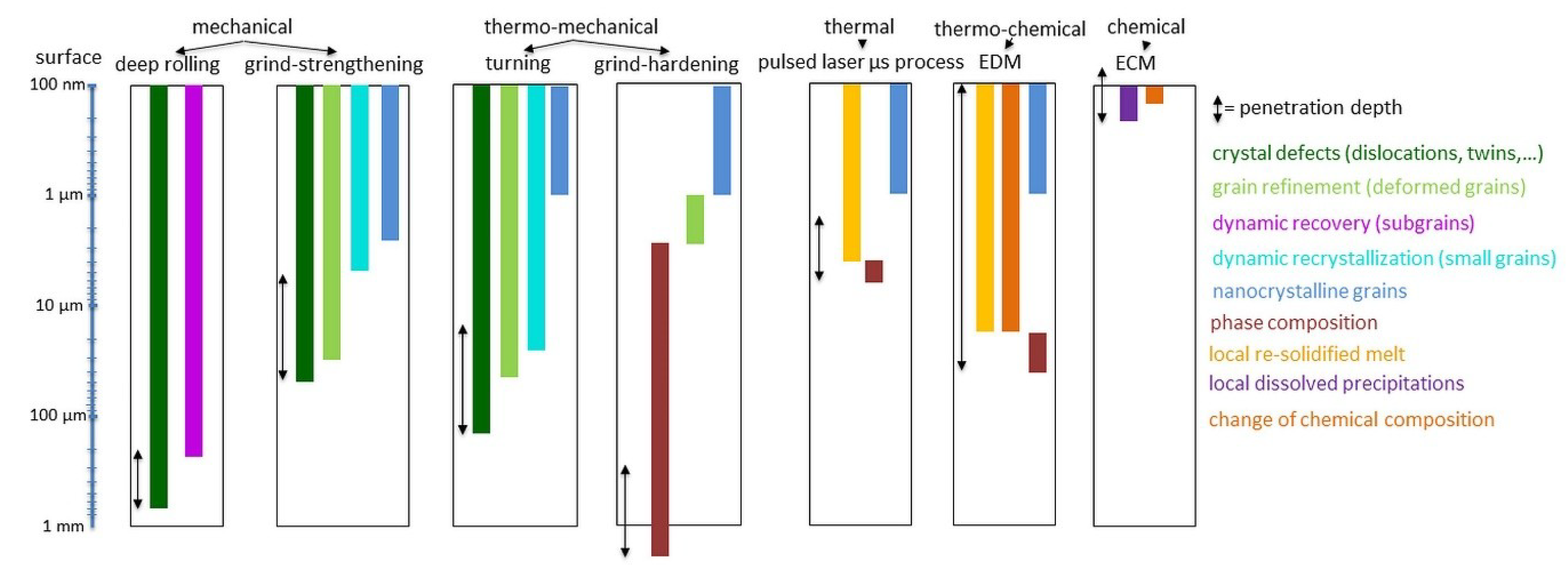
| Process | Main Impact | Mechanisms | Measured Modifications |
|---|---|---|---|
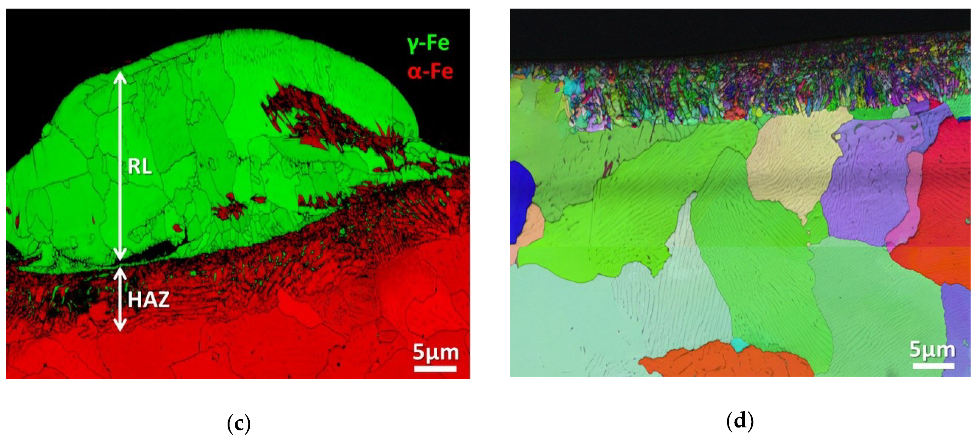
| deep rolling | mechanical | dislocation formation/accumulation/rearrangement, dynamic recovery, work hardening | compressive residual stresses, dislocation density, dislocation arrangements, subgrain boundaries, misorientation |
| grind-strengthening | mechanical | dislocation formation/accumulation/rearrangement, continuous dynamic recrystallization, work hardening | compressive residual stresses, shear stresses, dislocation density, misorientation, grain sizes, texture |
| hard turning | thermo-mechanical | continuous dynamic recrystallization, work hardening, annealing | residual stresses, shear stresses, dislocation density, misorientation, grain sizes, texture |
| grind-hardening | thermo-mechanical | continuous dynamic recrystallization, phase transformation, diffusion of carbon, annealing | residual stresses, grain sizes, carbon diffusion, phase contents |
| induction hardening | thermal | diffusion, phase transformation | residual stresses, grain sizes, carbon diffusion, phase contents |
| pulsed (µs) laser processing | thermal | melting/solidification, diffusion, phase transformation | residual stresses, dislocation density, grain sizes, carbon diffusion, phase contents, dendrite arm distances |
| EDM (roughing) | thermo-chemical | melting/solidification, phase transformation, diffusion | residual stresses, dislocation density, grain sizes, carbon diffusion, phase contents, dendrite arm distances |
| ECM | chemical | local dissolution of phases, chemical reactions | phase concentration, oxides and nitrates in surface zone |
© 2020 by the authors. Licensee MDPI, Basel, Switzerland. This article is an open access article distributed under the terms and conditions of the Creative Commons Attribution (CC BY) license (http://creativecommons.org/licenses/by/4.0/).
Share and Cite
Borchers, F.; Clausen, B.; Eckert, S.; Ehle, L.; Epp, J.; Harst, S.; Hettig, M.; Klink, A.; Kohls, E.; Meyer, H.; et al. Comparison of Different Manufacturing Processes of AISI 4140 Steel with Regard to Surface Modification and Its Influencing Depth. Metals 2020, 10, 895. https://doi.org/10.3390/met10070895
Borchers F, Clausen B, Eckert S, Ehle L, Epp J, Harst S, Hettig M, Klink A, Kohls E, Meyer H, et al. Comparison of Different Manufacturing Processes of AISI 4140 Steel with Regard to Surface Modification and Its Influencing Depth. Metals. 2020; 10(7):895. https://doi.org/10.3390/met10070895
Chicago/Turabian StyleBorchers, Florian, Brigitte Clausen, Sandro Eckert, Lisa Ehle, Jeremy Epp, Simon Harst, Matthias Hettig, Andreas Klink, Ewald Kohls, Heiner Meyer, and et al. 2020. "Comparison of Different Manufacturing Processes of AISI 4140 Steel with Regard to Surface Modification and Its Influencing Depth" Metals 10, no. 7: 895. https://doi.org/10.3390/met10070895