Article

Measurement of Surface Velocity in a 150 mm × 1270 mm Slab Continuous-Casting Mold

1
School of Metallurgical and Ecological Engineering, University of Science and Technology Beijing, Beijing 100083, China
2
School of Materials Science and Engineering, Hebei University of Science and Technology, Shijiazhuang 050018, China
*
Author to whom correspondence should be addressed.
Metals 2020, 10(4), 428; https://doi.org/10.3390/met10040428
Submission received: 8 March 2020 / Revised: 20 March 2020 / Accepted: 22 March 2020 / Published: 25 March 2020
(This article belongs to the Special Issue Numerical Modelling in Steel Metallurgy)

Abstract

:
Surface velocity in the continuous-casting mold needs to be studied to better control the quality of steel products. In this paper, the measurement of surface velocity in a 150 mm × 1270 mm slab continuous-casting mold was investigated. Taking the slag layer into consideration, a numerical simulation was performed which was validated by a particle image velocimetry test. A nail-board experiment was also conducted to measure surface velocity in the continuous-casting mold. The effect of nail diameter used in nail-board experiment on the measurement of the surface velocity was also discussed to improve the precision of nail-board experiment result. The results showed that the maximum surface velocity was 0.739 m/s around the mid-section of the free surface, and the results of nail-board experiments were more accurate when the steel nail diameter was 10 mm.

1. Introduction

The continuous-casting mold plays an important role in the production of high-quality defect-free steel materials [1,2]. The fluctuation of the liquid level in the mold directly affects the quality of the steel product. This liquid level fluctuation, especially at a high casting speed, readily leads to problems such as slag entrapment whereupon the slag is further captured by the solidification front, resulting in slab defects [3,4,5,6]. Therefore, in reducing the secondary oxidation and slag entrapment behavior of molten steel, it is important to measure surface velocity in the mold and control the flow field in the mold [7,8]. Controlling fluctuations of the free surface can improve the quality of the steel product and is a crucial aspect of continuous-casting production [9,10,11,12,13].
The development of numerical simulation technology has made it possible to evaluate liquid level characteristics in a continuous-casting mold under working conditions and to judge slag entrapment. Thomas et al. [14] conducted a nail-board experiment to test the velocity field, pressure field, and liquid surface shape, using a fluid dynamics analysis program (FIDAP) to simulate the nail experiment, but only one nail was used and no plant experiment was conducted to validate the results. Liu et al. [15] found that the optimal duration of insertion of the steel nails decreased with decreasing nail diameter, and the immersion time of steel nails should be controlled at 3–5 s. The accuracy of the measurement results depends on the latter requirement because the steel slag on the nail re-melts if the immersion time is too long. However, the effect of nail diameter in industrial experiments has not been investigated until now.
In this paper, a nail-board experiment was used to measure the surface velocity in a 150 mm × 1270 mm slab continuous-casting mold at the Tang Steel Company (Tangshan, China). The effect of the steel nails’ diameter in the nail-board experiment was also discussed to improve the precision of measurement results. Surface velocity in the mold was studied using the large eddy simulation coupling volume-of-fluid method, which was validated by a particle image velocimetry (PIV) test. The plant experiment (the nail-board experiment) was carried out to further validate the results of numerical simulation and discuss the effect of the steel nail diameter on the measurement of surface velocity.

2. Experimental Section

2.1. Governing Equations

A volume-of-fluid model was used to track the interface between phases. The continuity and momentum conservation equations for the fluid are
α q ρ q t + · ( ρ q α q u q ) = 0
q = 1 n α q = 1
ρ = α s l a g ρ s l a g + ( 1 α s l a g ) ρ s t e e l
where αslag is the volume fraction of slag; ρsteel is the density of molten steel (kg/m3); ρslag is the density of slag (kg/m3); uq is the fluid velocity vector of phase q (m/s); and t is time (s). We have
u i t + u i u j x j x j ( μ e f f u i x j ) = 1 ρ p x i τ i j x j
μ e f f = μ + μ t
where μ is the dynamic viscosity (Pa∙s) and μt is the sub-grid-scale eddy-viscosity coefficient.
A sub-grid-scale stress is generated in the process of analyzing large eddies and modeling small eddies:
τ i j = 1 3 τ k k δ i j 2 μ t S i j ¯
where τkk is ignored owing to the low-Mach-number flow and δij is the Kronecker constant. Sij is the strain rate tensor, expressed as
S ¯ i j = 1 2 ( u i ¯ x j + u j ¯ x i ) .

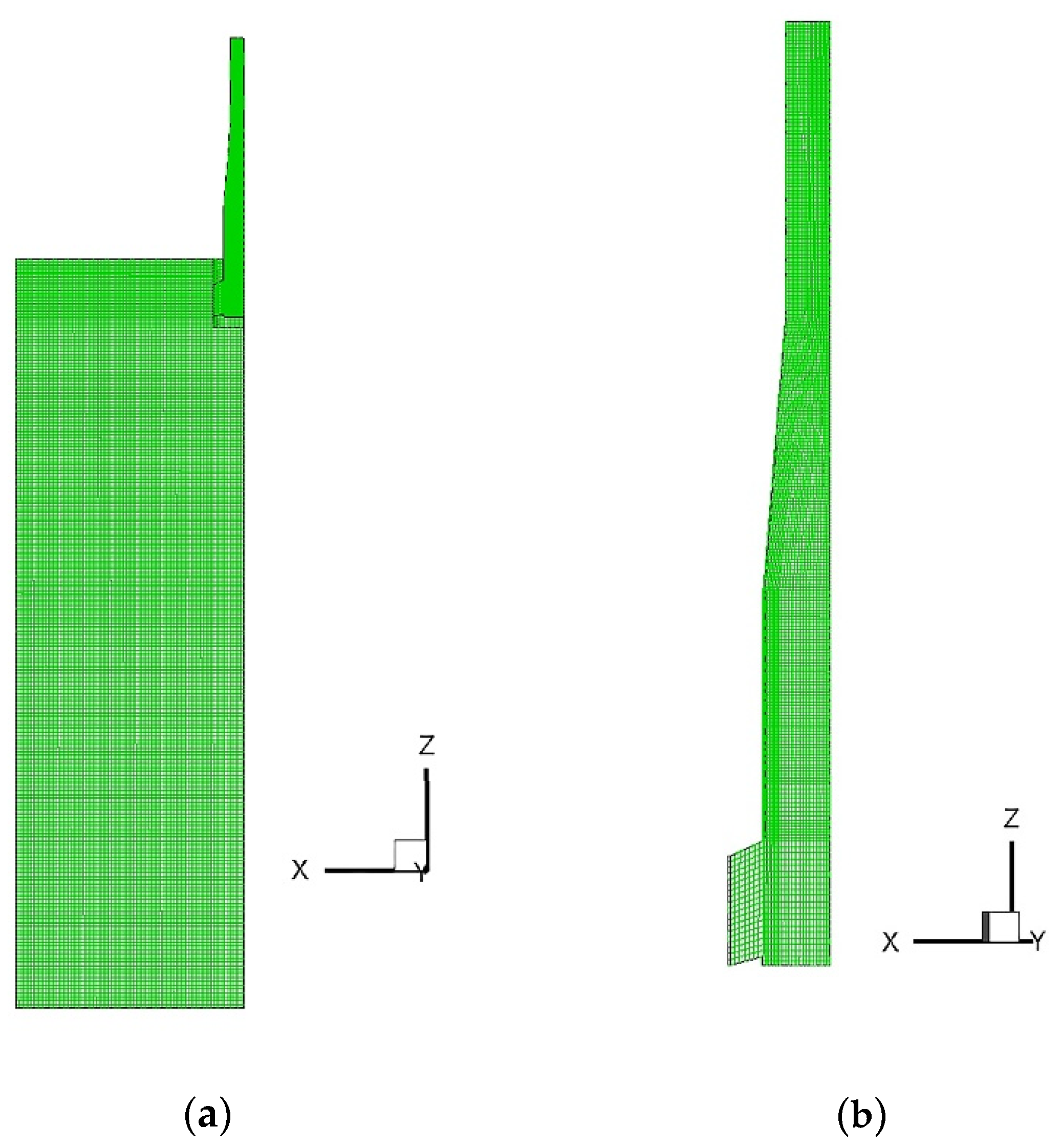
2.2. Boundary Conditions and Computational Details

Table 1 gives the mold dimensions. The symmetry condition at the mold center was taken into consideration to save computational resources. The fluid region in the mold during the continuous-casting process was solved with 500,000 hexahedral structured cells as shown in Figure 1.
According to the mass conservation law, the inlet velocity is
v i n l e t = 4 u c a s t i n g L o u t l e t W o u t l e t π D i n l e t 2
where ucasting is the casting speed; Loutlet is the length of the outlet; Woutlet is the width of the outlet; and Dinlet is the diameter of the round opening. For a casting speed of 1.6 m/min, an inlet velocity of 1.329 m/s was calculated using Equation (8). It was assumed that the initial slag layer was stationary. The outlet was set as open, with zero relative pressure at the surface. Table 2 gives the physical properties of the slag and molten steel used in mathematical simulations [16].
The commercial software FLUENT (17.0, FLUENT, Pittsburgh, PA, US) was used for large eddy simulation modeling using a DELL eight-core personal computer (DELL, Xiamen, China) with 64.0 GB of random-access memory and a 3.40-GHz Intel® Xeon processor (Intel, Beijing, China) for parallel computing. The submerged depth was 90 mm, and the modeled time was about 15 s with a time step of 0.001 s.

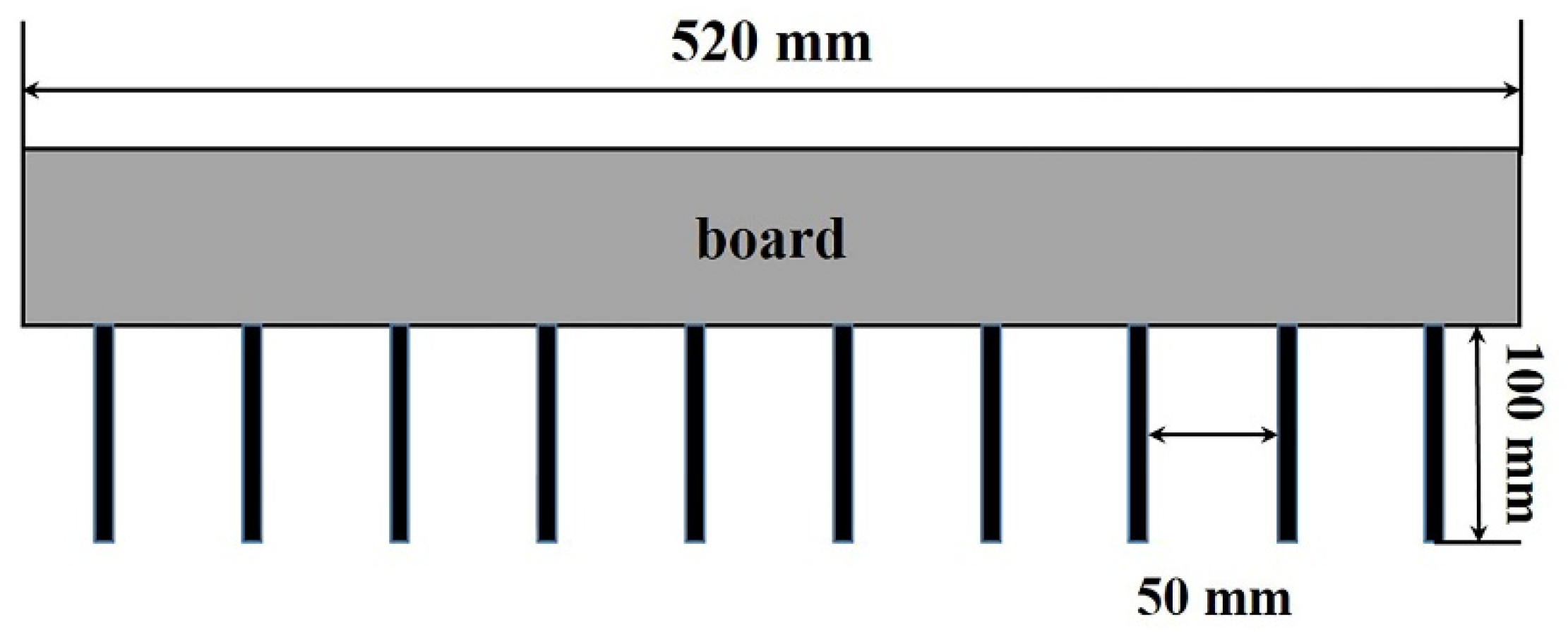
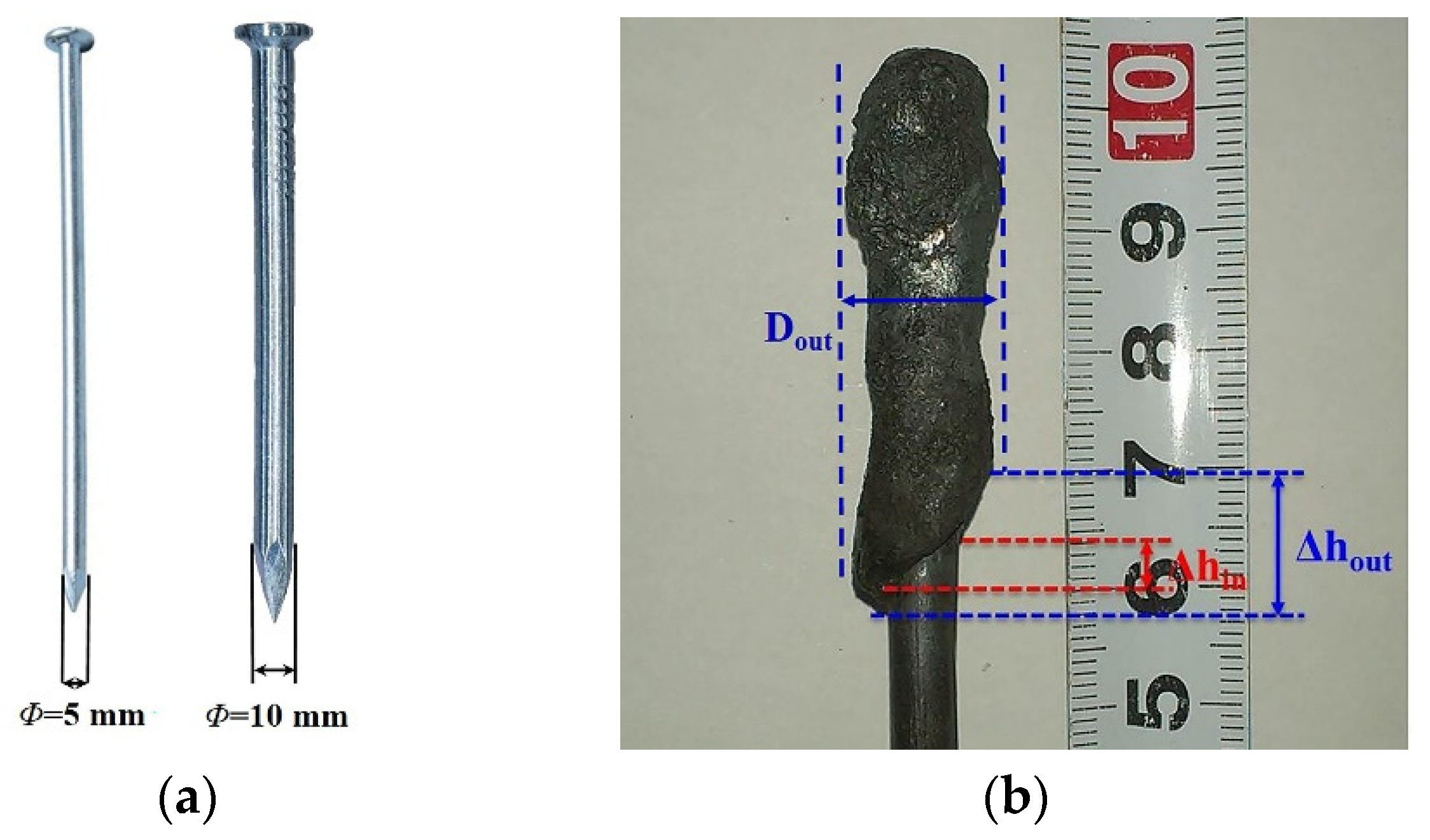
2.3. Experimental Set-Up

A 0.5 scale water modeling experiment apparatus, consisting of mold with a submerged nozzle, water tank, electronic flowmeter, and pump, was set up. The bottom of the mold was connected to the water tank on the top through water pipes. After flowing out of the outlet, water was pumped back to the top tank. The velocity field in the water modeling was measured by particle image velocimetry (PIV). The laser from the side of the mold was produced by a laser transmitter. Two CCD cameras placed in front of the wide face of the mold were used to record the tracer particle movement.
Plant experiments were carried out using a continuous-casting mold having dimensions of 150 mm × 1270 mm. In the first experiment, the nail board had nails with a diameter of 5 mm. The nails were numbered 1–10 from right to left, as shown in Figure 2. In the second experiment, the nails had a diameter of 10 mm and were again numbered 1, 2,…10 from right to left. The spacing of nails was 50 mm.

3. Results and Discussion

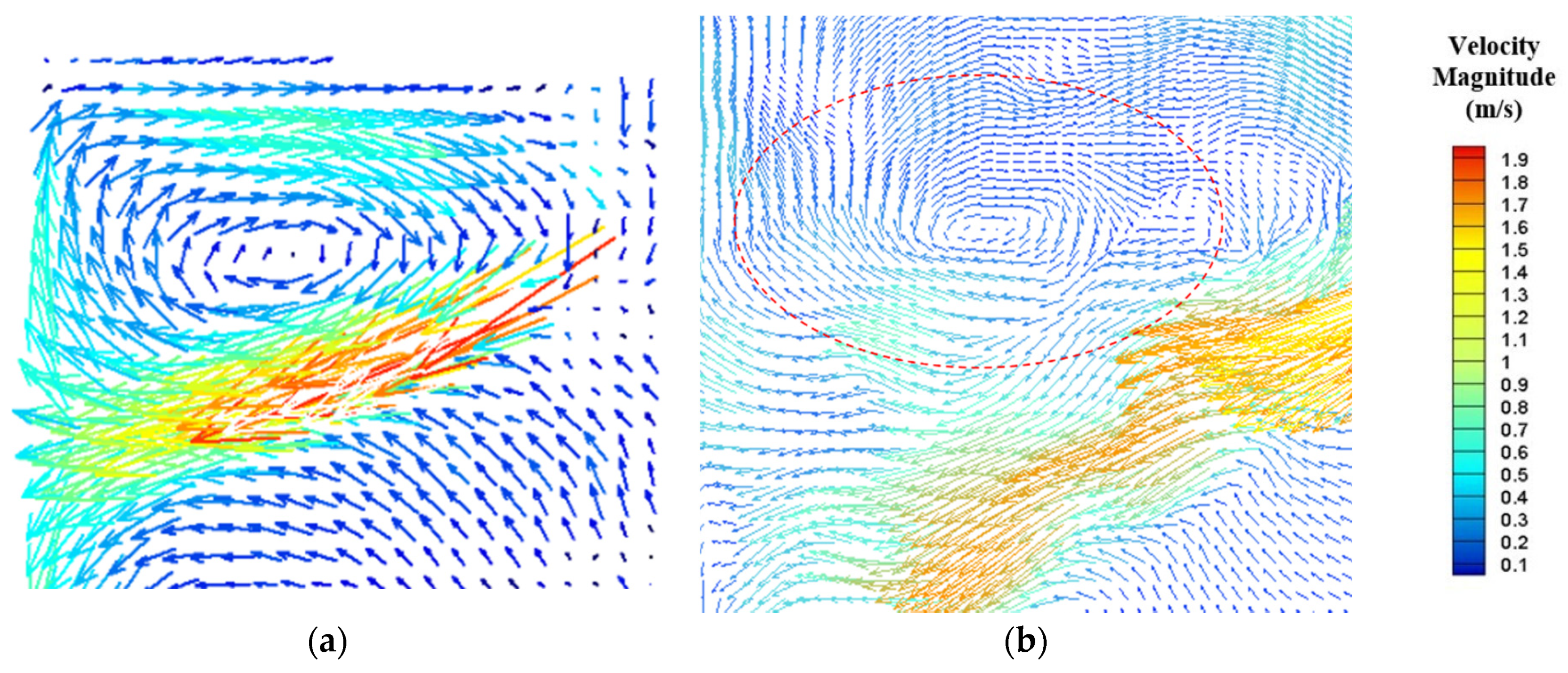
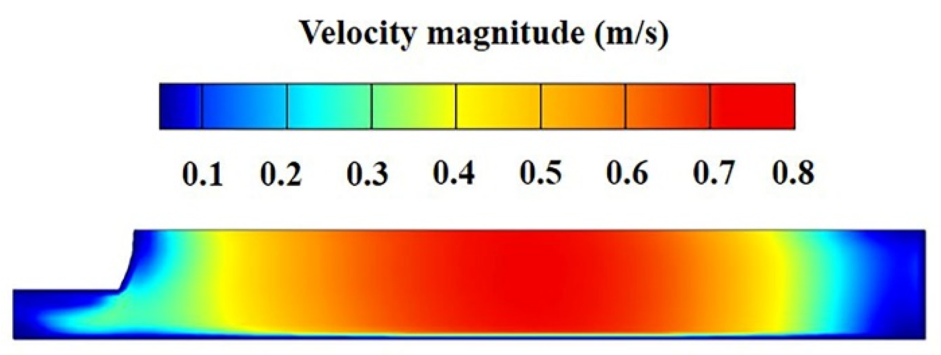
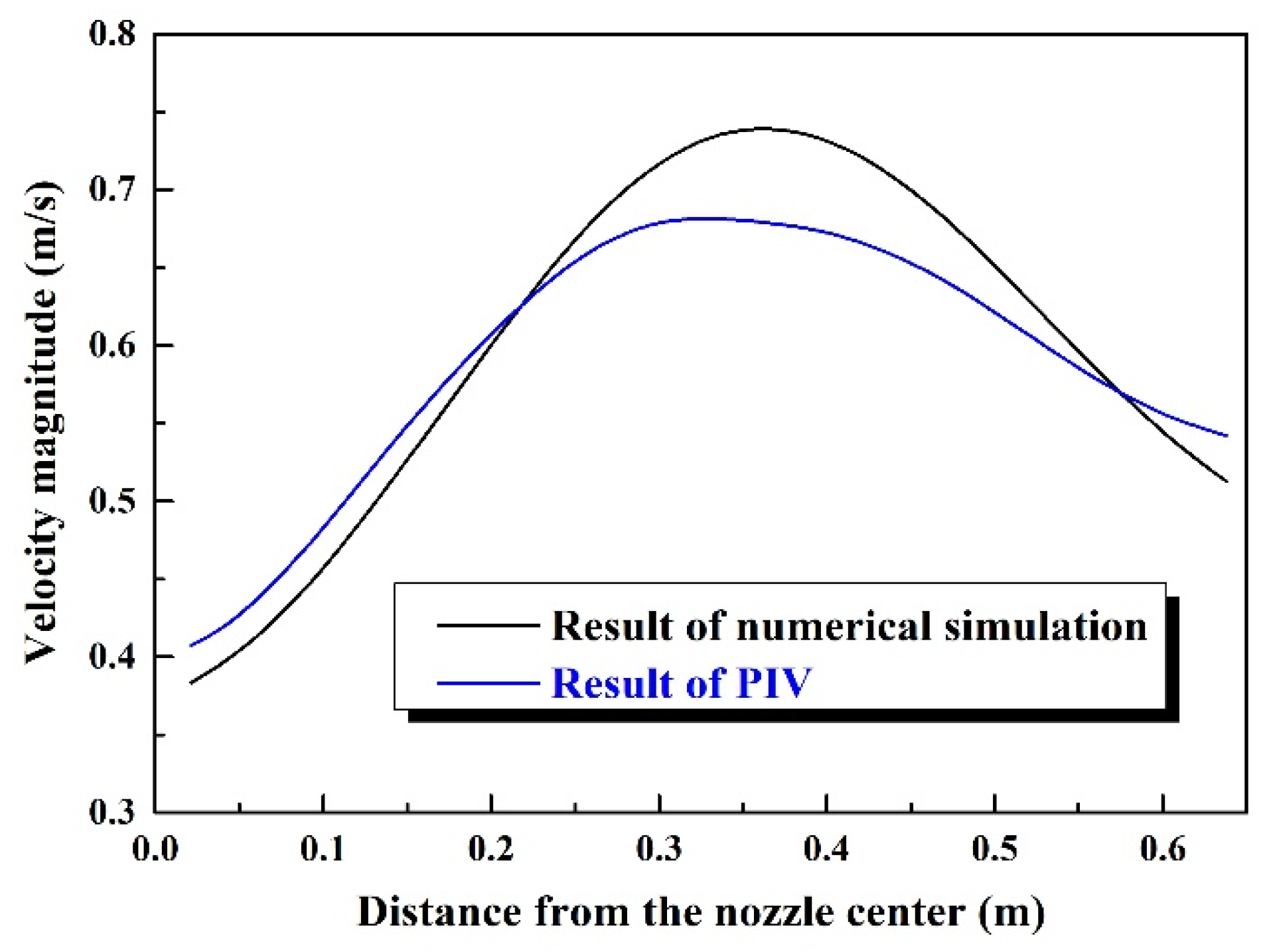
3.1. Surface Velocity

Figure 3 shows velocity vectors at the wide face of the mold obtained by computational fluid dynamics modeling and PIV testing.
It can be seen that the results of PIV testing agree with the results of numerical simulation, demonstrating the accuracy of the computational fluid dynamics modeling. Compared with the results of the PIV test, the results of numerical simulation are more precise and present smaller vortices. However, the velocity distributions obtained by the two methods are basically the same. There are two strands of swirling flow in the mold during continuous casting, namely an upper part and lower part. For the upper part, the effect of the velocity magnitude on surface fluctuation is important. When flow rushes out of the nozzle port, it moves forward along the nozzle angle and then impacts the narrow face, producing two streams. The upward flow disturbs the molten steel at the free surface, sometimes resulting in surface fluctuation and even slag entrapment.
Figure 4 is the contour of velocity magnitude at free surface by numerical simulation. It shows that the velocity was highest (0.739 m/s) around the mid-section of the surface and lowest on both sides. The higher the surface velocity, the more easily the liquid level fluctuated or slag entrapment occurred. The velocity distributions of the free surface along the central line of the nozzle obtained using the two methods are compared in Figure 5 (for the same line measured in the plant experiments). The results of PIV testing show the same trend in that the velocity was highest (0.682 m/s) around the mid-section of the surface and lowest at the two sides. In the range of 0.3 m to 0.5 m from the nozzle center, the velocity distributions of the two methods were slightly different and the maximum relative error of the free-surface velocity was 8%. It is suggested that the two methods validate each other and both numerical results and PIV results are reliable.
In summary, the results of numerical simulation are in good agreement with the PIV data and the maximum surface velocity was 0.739 m/s around the mid-section of the free surface.

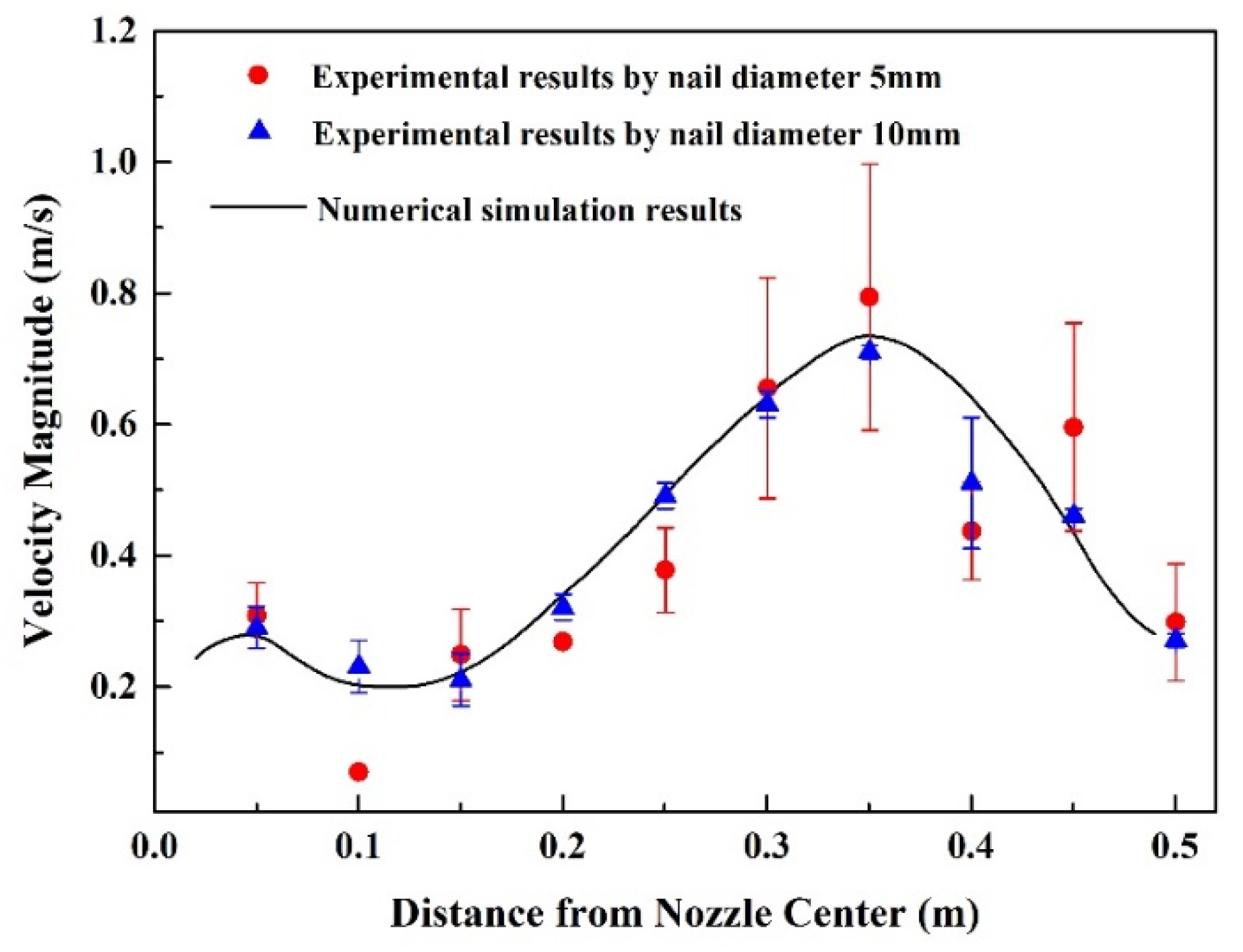
3.2. Effects of Nail Diameter Used in the Nail-Board Experiment

To further validate the results of surface velocity calculated by numerical simulation, the surface velocity Vm of plant experiment results could be obtained as [17,18]
V m = 0.624 Δ h l u m p 0.567 φ l u m p 0.696
where Δhlump is the difference between the heights on the two sides of the steel nail and Δhin and Δhout, φlump is the difference between Din and Dout, as shown in Figure 6.
The periphery of the block solidified on the nail was approximately circular, and the outer diameter is expressed as
D o u t = C L u m p π
where Clump is the circumference.
Figure 7 presents the results of numerical simulation and industrial experiments given in Table 1 and Table 2. Compared with the results obtained using the 5-mm-diameter nails, the results obtained using the 10-mm-diameter nails were closer to the numerical simulation results. The velocity curves obtained in numerical simulation had two peaks, and the velocity was highest around the mid-section (0.35 m away from the nozzle center). Even considering the error bars, the results obtained using the 10-mm-diameter nails were closer to the numerical simulation results. This shows that the diameter of steel nails being too small (5 mm here) leads to instability of the solidified lump remaining on a steel nail and increases inaccuracies in the results.
Error analysis needs to be discussed, as there were no repetitions in the plant experiment. In this paper, the diameter of a block solidified on a steel nail is in the range of 10–16 mm. According to the error evaluation of nail dipping conducted by Ji et al. [19], error is included in the form of error bars in Figure 7. The error in the surface velocity decreased as the nail diameter increased. The maximum error for the 5-mm-diameter steel nails was 0.205 m/s (in the mid-section 0.35 m from the nozzle center), while the minimum error was 0 m/s. The maximum error for the 10-mm-diameter steel nails was 0.1 m/s (at 0.4 m from the nozzle center) while the minimum error was 0.01 m/s. Generally, the error for a 10-mm-diameter nail was smaller than that for a 5-mm-diameter nail. Additionally, high errors were seen in the region between the mid-section and narrow face of the mold, which indicates that the measurement error was higher for a higher flow velocity. Steel nails with a diameter of 10 mm should therefore be chosen to measure the surface velocity.

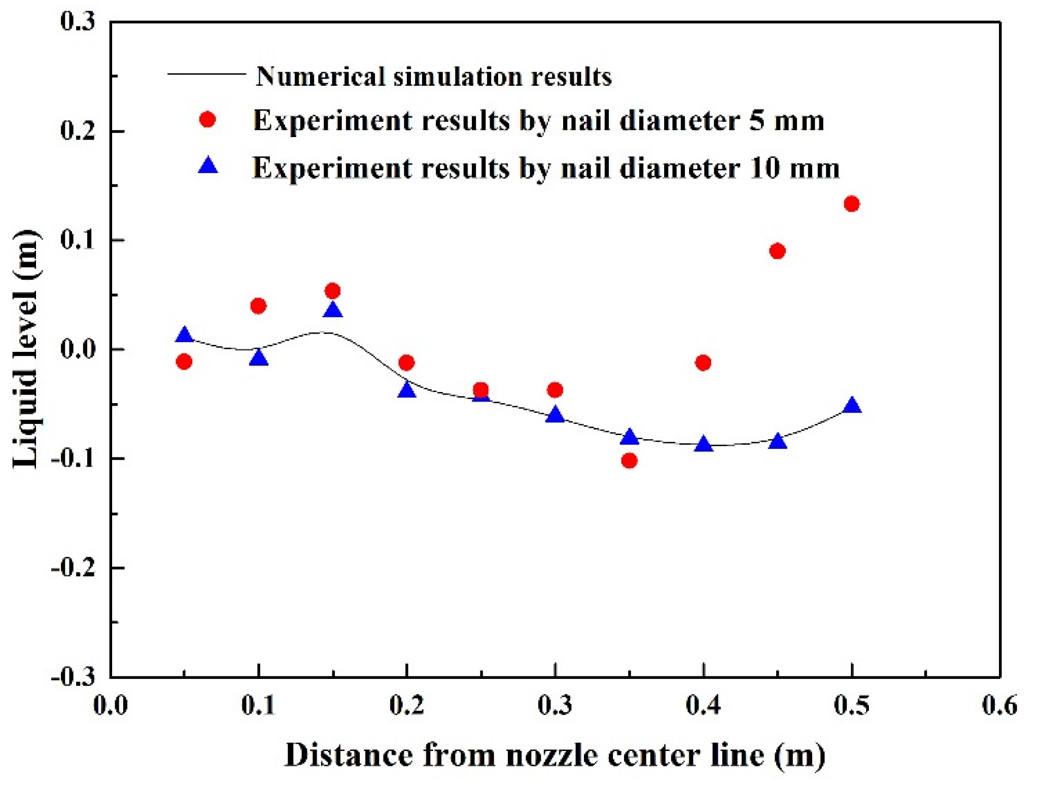
3.3. Interface Shape

Figure 8 shows the interface shapes obtained by numerical simulation and industrial experiments. In the industrial experiments, the average height of left and right sides of the solidified lump around the nail was taken as the liquid level.
There are two troughs in the curve obtained by numerical simulation. Near the top of the nozzle port, there was a slight fluctuation of the liquid level due to the backflow of the upper circular stream after impinging on the narrow face of the mold. The fluctuation of the liquid level was affected by the impingement of the upper stream on the narrow side of the mold, such that there was an obvious bulge in the interface shape near the narrow face of the mold. Overall, the fluctuation of the interface shape was consistent with the velocity field.
A comparison of the results obtained in the nail-board experiment using nails having a diameter of 5 mm with the results of numerical simulation shows that the curve of the liquid level measured in the industrial experiment fluctuated greatly. There was no slight disturbance of the liquid level at the top of the nozzle port. There was a sharp uplift 0.35 m from the nozzle center. The interface shape measured using steel nails with a diameter of 10 mm also had two troughs, but the overall change in the interface shape was relatively stable. At the same position (i.e., 0.35 m from the nozzle center), the liquid level dropped slightly and then rose slowly. In terms of fluctuation of the liquid level, the results obtained using the steel nails with a diameter of 10 mm were more similar to the numerical results.

4. Conclusions

To measure the surface velocity in a 150 mm × 1270 mm slab continuous-casting mold, numerical simulation was used in this paper. Then, the results of numerical simulation were validated in a PIV test. A nail-board experiment was also conducted in a 150 mm × 1270 mm continuous-casting mold. The effect of nail diameter in the nail-board experiment on the measurement of the surface velocity was also discussed to improve the precision of the nail-board experiment results. The following conclusions are drawn from the results of this work.
(1) The results of numerical simulation show that the surface velocity around the mid-section, 0.739 m/s, is higher than the velocity at either side. The results of numerical simulation are in good agreement with the PIV results.
(2) When the diameter of a steel nail is 10 mm, the measured surface velocity is closer to the value predicted in numerical simulation. Additionally, the error is less than that in results obtained using 5-mm-diameter steel nails.
(3) Results of the fluctuation of the liquid level obtained using 10-mm-diameter steel nails are more similar to the numerical results in that there are two troughs overall, but the overall change in the interface shape is relatively stable.
(4) Greater surface velocities induce violent impacts on the steel nails. Correspondingly, measurement errors tend to be larger for a high surface velocity.

Author Contributions

Data curation, J.F., J.L.; methodology, S.Y.; writing—original draft, Y.W.; writing—review and editing, S.Y. All authors have read and agreed to the published version of the manuscript.

Funding

This research was funded by the National Natural Science Foundation of China under grant numbers 51822401 and Fundamental Research Funds for the Central Universities FRF-TP-18-009C1.

Acknowledgments

Thanks are due to Glenn Pennycook, from Liwen Bianji, Edanz Group China (www.liwenbianji.cn/ac), for editing the English text of a draft of this manuscript.

Conflicts of Interest

The authors declare no conflict of interest.

References

  1. Svensson, J.K.S.; Memarpour, A.; Brabie, V.; Jönsson, P.G. Studies of the decarburisation phenomena during preheating of submerged entry nozzles (SEN) in continuous casting processes. Ironmak. Steelmak. 2017, 44, 108–116. [Google Scholar] [CrossRef] [Green Version]
  2. Sun, H.; Li, L. Formation and control of macrosegregation for round bloom continuous casting. Ironmak. Steelmak. 2015, 42, 683–688. [Google Scholar] [CrossRef]
  3. Zheng, S.G.; Zhu, M.Y. Study on mechanism of mould powder entrapment in funnel type mould of flexible thin slab casting machine. Ironmak. Steelmak. 2014, 41, 507–513. [Google Scholar] [CrossRef]
  4. McDavid, R.; Thomas, B.G. Flow and thermal behavior of the top surface flux/powder layers in continuous casting molds. Metall. Mater. Trans. B 1996, 27, 672–685. [Google Scholar] [CrossRef]
  5. Cukierski, K.; Thomas, B.G. Flow Control with Local Electromagnetic Braking in Continuous Casting of Steel Slabs. Metall. Mater. Trans. B 2008, 39, 94–107. [Google Scholar] [CrossRef]
  6. Ji, C.; Li, J.; Lin, X. Study of Mold Fluid Flow on a New Type Nozzle Bottom in Continuous Casting of Steel. Adv. Mater. Res. 2011, 284–286, 1205–1208. [Google Scholar]
  7. Thomas, B.G. Fluid flow in the mold. In Making, Shaping and Treating of Steel, 11th ed.; AISE Steel Foundation: Pittsburgh, PA, USA, 2003; Chapter 14; pp. 141–181. [Google Scholar]
  8. Timmel, K.; Eckert, S.; Gerbeth, G. Experimental Investigation of the Flow in a Continuous-Casting Mold under the Influence of a Transverse, Direct Current Magnetic Field. Metall. Mater. Trans. B 2011, 42, 68–80. [Google Scholar] [CrossRef]
  9. Chen, W.; Shen, H. Large Eddy Simulation of Transient Flow Field in Continuous Casting Mold. Contin. Cast. 2012, 2, 1–4. [Google Scholar]
  10. Banderas, A.R.; Perez, R.S.; Morales, R.D.; Ramos, J.P.; García, L.D.; Cruz, M.D. Mathematical simulation and physical modeling of unsteady fluid flows in a water model of a slab mold. Metall. Mater. Trans B 2004, 35, 449–460. [Google Scholar] [CrossRef]
  11. Chaudhary, R.; Lee, G.G.; Thomas, B.G.; Cho, S.M.; Kim, S.H.; Kwon, O.D. Effect of Stopper-Rod Misalignment on Fluid Flow in Continuous Casting of Steel. Metall. Mater. Trans. B 2011, 42, 300–315. [Google Scholar] [CrossRef]
  12. Chen, Y.; Zhang, L.; Yang, S.; Li, J. Water Modeling of Self-Braking Submerged Entry Nozzle Used for Steel Continuous Casting Mold. JOM 2012, 64, 1080–1086. [Google Scholar] [CrossRef]
  13. Huang, X.; Thomas, B.G. Modeling of transient flow phenomena in continuous casting of steel. Can. Metall. Q. 1998, 37, 197–212. [Google Scholar] [CrossRef]
  14. Rietow, B.; Thomas, B.G. Using Nail Board Experiments to Quantify Surface Velocity in the CC Mold. In Proceedings of the AISTech Steelmaking Conference, Warrendale, PA, USA, 5–8 May 2008. [Google Scholar]
  15. Liu, R.; Thomas, B.G.; Sengupta, J.; Chung, S.D.; Trinh, M. Measurements of molten steel surface velocity and effect of stopper-rod movement on transient multiphase fluid flow in continuous casting. ISIJ Int. 2014, 54, 2314–2323. [Google Scholar] [CrossRef] [Green Version]
  16. Hagemann, R.; Schwarze, R.; Heller, H.P.; Scheller, P.R. Model investigations on the stability of the steel-slag interface in continuous-casting process. Metall. Mater. Trans. B 2013, 44, 80–90. [Google Scholar] [CrossRef]
  17. Liu, R.; Sengupta, J.; Yavuz, M.M.; Thomas, B.G. (Eds.) Effects of Stopper Rod Movement on Mold Fluid Flow at ArcelorMittal Dofasco’s No. 1 Continuous Caster. In Proceedings of the AISTech 2011, Indiana, Indianapolis, 2–5 May 2011. [Google Scholar]
  18. Liu, R.; Sengupta, J.; Crosbie, D.; Chung, S.; Trinh, M.; Thomas, B.G. Sensors, Sampling, and Simulation for Process Control; John Wiley & Sons, Inc.: Hoboken, NJ, USA, 2011. [Google Scholar]
  19. Ji, C.; Li, J.; Tang, H.; Yang, S. Effect of EMBr on flow in slab continuous casting mold and evaluation using nail dipping measurement. Steel Res. Int. 2013, 84, 259–268. [Google Scholar] [CrossRef]
Figure 1. Mesh used in numerical simulation: (a) side view and (b) submerged entrance nozzle.
Metals 10 00428 g001
Figure 2. Schematic diagram of the nail board.
Metals 10 00428 g002
Figure 3. Velocity vectors at the wide face of the mold. (a) Results of particle image velocimetry (PIV) testing; (b) results of numerical simulation.
Metals 10 00428 g003
Figure 4. Contour of velocity magnitude at free-surface by numerical simulation.
Metals 10 00428 g004
Figure 5. Velocity distribution of the free surface along the central line of the nozzle.
Metals 10 00428 g005
Figure 6. Schematic diagram of key parameters: (a) nail diameter Din; (b) Δhin, Δhout, and Dout.
Metals 10 00428 g006
Figure 7. Surface velocity in the numerical simulation results and industrial experiment results.
Metals 10 00428 g007
Figure 8. Fluctuations of the liquid level in the results of the numerical simulation and industrial experiment.
Metals 10 00428 g008
Table 1. Mold dimensions.
Mold Height, mMold Length, mMold Width, mSubmerged Depth, mInlet Diameter, m
1.101.270.150.070.074
Table 2. Physical properties of the steel and slag in mathematical simulations.
Molten Steel Viscosity, Pa·sSlag Viscosity, Pa·sMolten Steel Density, kg/m3Slag Density, kg/m3Interface Tension (σsteel/slag), N/m
0.00550.4702025001.2

