Effect of Groove Structure on Lubrication Performance of Water-Lubricated Stern Tube Bearings


School of Industry, Jining University, Qufu 273199, China
Lubricants 2023, 11(9), 374; https://doi.org/10.3390/lubricants11090374
Submission received: 25 June 2023
/
Revised: 27 August 2023
/
Accepted: 28 August 2023
/
Published: 5 September 2023
(This article belongs to the Special Issue Water-Lubricated Bearings)
Abstract
:This study investigated the lubrication characteristics (i.e., the groove ratio and width) of water-lubricated stern tube bearings, based on the flexibility matrix method and lubrication theory. Considering the elastic deformation of the lining, a fluid structure interaction (FSI) model of the surface micro-groove texture of a water-lubricated stern tube bearing was established, and the correctness and rationality of the model were verified by experiments. Micro-grooved, surface-lubricated, water-lubricated stern tube bearings with three different cross-sectional shapes (rectangular, circular, and triangular) were designed. The influences of the groove area ratio and width on the bearing load-carrying capacity and friction coefficient were analyzed. At a groove area ratio of 0.31, the load-carrying capacity of the rectangular grooved stern tube bearing reached the maximum value and the friction coefficient reached the minimum value. It is recommended to design and use water-lubricated stern tube bearings, especially Thordon water-lubricated stern tube bearings, with rectangular micro-grooves, with a groove area ratio of 0.30–0.32, so that the best lubrication performance can be obtained. With the increase in the micro-groove width, the lubrication of water-lubricated stern tube bearings with partial rectangular micro-grooves is significantly better than that of others. Under the same conditions, the bearing load-carrying capacity and friction performance of local groove stern bearings is significantly better than that of global groove stern bearings.
1. Introduction
The water-lubricated stern tube bearing is a crucial supporting component in a propulsion system, with low-viscosity seawater or freshwater as the lubricant [1,2,3,4]. Considering the pollution caused by the leakage of lubricating fluid to the environment, this type of bearing has natural environmental advantages. In the operation of a water-lubricated stern tube bearing, water is both the lubricant and the coolant. Given that the specific heat of water is greater than that of lubricating oil, the cooling effect is good, and long-term operation will not result in the overheating phenomenon or shaft holding phenomenon. However, due to the low viscosity of water, water-lubricated stern tube bearings exhibit poor lubrication performance, resulting in the lubricating water film not being formed effectively. Specifically, the water-lubricated stern tube bearing’s load-carrying capacity is insufficient, and the friction coefficient is high, which affects the reliability and safety of the whole dynamic system [5,6]. At present, the arrangement of the surface microtexture on the inner surface of the bearing is an effective means by which to improve the lubrication effect of a water-lubricated stern tube bearing [7,8]. The types of surface textures mainly include micro-grooves and micro-dimples. Scholars have studied the location, shape, and geometry of micro-dimples. Tala-Ighil et al. pointed out that the texture of the whole bearing surface does not necessarily improve the performance of the bearing, but the complete texture will have a positive effect on the low journal rotation speed, while the local texture at the outlet of the active pressure zone has a positive effect on the high rotation speed [9,10]. Choudhury et al. studied the dimple shape of an artificial hip joint, and the results show that a prosthesis with a square dimple array is the best in the formation of the lubricating film of the artificial hip joint [11]. Shinde et al. studied the performance of conical fluid dynamic journal bearings using numerical and experimental methods. On a smooth surface, the local texture of the bearing surface in the 90–180° area increased the maximum fluid film pressure by 42.08% [12]. Dong Ning et al. established a mathematical model of the elastohydrodynamic lubrication of surface texture sliding bearings, and numerically calculated and analyzed the pits in three forms: circular, rectangular, and isosceles triangular. It was found that the pits have a significant effect on the peak pressure fluctuation and film thickness of the bearing [13,14]. The parameters that have been studied include the shape of the texture, the depth of the texture, the number of textures, the percentage of textures, and the surface roughness. The findings demonstrate that specific parameter textures on the bearing surface can increase the load-carrying capacity by 36.32% and reduce frictional torque by 1.66% compared to bearings without texture. However, the numerical model has not been verified by experiments, and the effect of elastic deformation on the lining material has not been considered [15]. Blatter et al. [16] conducted experimental research on the effect of micro-grooves using a pin-on-disk tribometer. They highlighted that appropriately sized and shaped micro-grooves can reduce wear and significantly extend the sliding life. Yuan et al. [17] designed and executed experiments to study the influence of groove orientation on friction performance. Their findings revealed that micro-grooves aligned perpendicularly or parallel to the sliding direction strongly impact the friction performance of sliding surfaces. Wahab et al. [18] experimentally investigated the effects of micro-grooves on the tribological behavior of an Al2O3-13%TiO2 coating. The results demonstrate that the textured coating effectively decreased the wear rate by entrapping wear debris within the grooves. Ali et al. [19] explored the behavior of transverse limited micro-grooves in EHL point contacts. They observed that surfaces with such micro-grooves exhibited lower friction and larger film thickness during reciprocation motion compared to smooth surfaces. Ehret et al. [20] studied the influence of waviness orientation in EHL point contacts on lubrication performance using the multigrid multi-integration method. Their results indicate that transverse waviness provide the best lubrication capability. Thakre et al. [21] conducted theoretical research on the impact of surface textures with various waveforms on the lubricating behavior of ionic liquids. The results highlight that the texture pattern and material combinations significantly affect micro-EHL contact behavior. Kaneta [22] and Shi [23] also investigated micro-grooves using numerical and experimental methods, respectively. Gong Jiayu et al. established a mathematical model of micro-groove water-lubricated stern bearings for fluid solid coupling, conducted strip specimen tests on a testing machine, and used orthogonal methods to study the influence of groove geometry and position on lubrication performance. The results show that the two types of water-lubricated stern bearings, namely, locally micro-grooved and globally micro-grooved, were significantly affected by the geometry and position, but the study only considered the effects of a single eccentricity and the distance between micro-grooves [24]. A numerical model based on the average flow Reynolds equation was developed and validated by Wu et al. [25]. The effects of three types of grooves (rectangular, triangular, and wedge-shaped), groove location, groove size, and number of grooves on the low-speed lubrication performance of a water-lubricated groove bearing were investigated. The water-lubricated bearing without grooves had poor lubrication performance at low speeds. The groove shape parameter has more influence on the lubrication performance. However, Wu’s study did not specify which structure of micro-groove bearing had the best performance and did not consider the effects of groove ratio and groove width on the lubrication performance of the water-lubricated stern tube bearing.
Therefore, although scholars have researched the effect of surface texturing on the lubrication characteristics of stern bearings, there has been no in-depth research on the influence of groove proportion and width. The main purpose of this study was to research the effects of different groove parameters, especially the micro-groove structure type, micro-groove occupancy ratio, and micro-groove width, on the lubrication performance of water-lubricated stern tube bearings. In this case, based on the flexibility matrix method and lubrication theory, the fluid solid coupling model of a surface micro-groove weave structure water-lubricated stern tube bearing was established to account for the elastic deformation of the liner, and the correctness and reasonableness of the model were verified through experiments. Three different cross-sectional shapes of micro-groove surface woven water-lubricated stern tube bearing (rectangle, circle, and isosceles triangle) were designed, and the influences of the groove ratio and width on the load-carrying capacity and friction coefficient of the water-lubricated stern tube bearing were compared and analyzed. This study provides a theoretical basis for the selection of grooves in water-lubricated stern tube bearings.
2. Mathematical Model
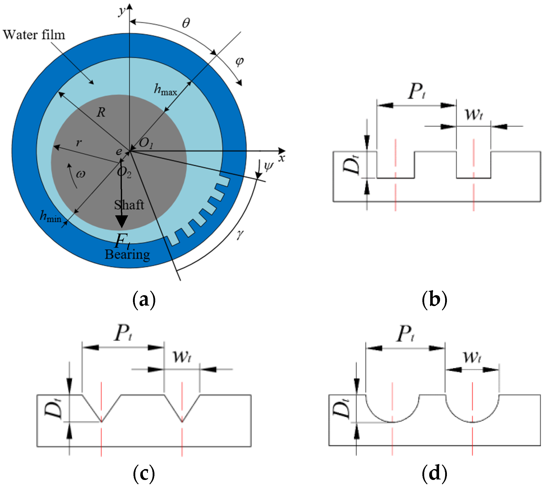
The lubrication model of the micro-groove stern tube bearing is shown in Figure 1.
R and r denote the inner radius of the bearing and the radius of the shaft, respectively, m; O1 and O2 are the centers of the bearing and the shaft, respectively; e is the eccentricity distance, m; θ is the attitude angle, °; hmin and hmax are the minimum and maximum film thickness, respectively, m; φ is the circumferential coordinate starting from the maximum film thickness, °; Ψ and γ are the circumferential starting angle and the circumferential arrangement range of the micro-groove area, respectively, °; Wt and Dt are the width and depth of the micro-grooves, respectively, m; Ft is the radial load applied on the spindle, N; ω is the rotational speed of shaft, rad/s; and Pt is the span of the micro-grooves, m.
The flow solid coupling theory for hydrodynamic lubricated stern tube bearings makes the following assumptions:
- (1)
- The inner diameter of the stern tube bearing, and the outer diameter of the shaft are much larger than the thickness of the water film.
- (2)
- There is no relative sliding between the water film and the inner wall of the stern tube bearing or the outer wall of the shaft.
- (3)
- Inertial forces and other volume forces of the water film are ignored.
- (4)
- Due to the extremely thin water film, small changes in water film pressure in the direction of the thickness are not considered.
- (5)
- Only the velocity gradient along the thickness direction of the water film is considered, and other directions are neglected.
- (6)
- Only the laminar flow of water is considered.
- (7)
- The variation of lubricant viscosity and density along the direction of water film thickness is not considered.
- (8)
- The working condition of the bearing is the metastability state; that is, the balance state of the bearing. The starting and stopping conditions are not considered.
- (9)
- The thermal effect of the shafting operation is ignored.
The Reynolds equation [26,27] for finite-width water-lubricated stern tube bearings in a steady state is
where x and y are the two coordinate directions of the water film, m; h is the water film thickness, m; p is the water film pressure, Pa; ω is the component of tangential velocity at the journal surface, rad/s; and η is the viscosity of the water, Pa·s.
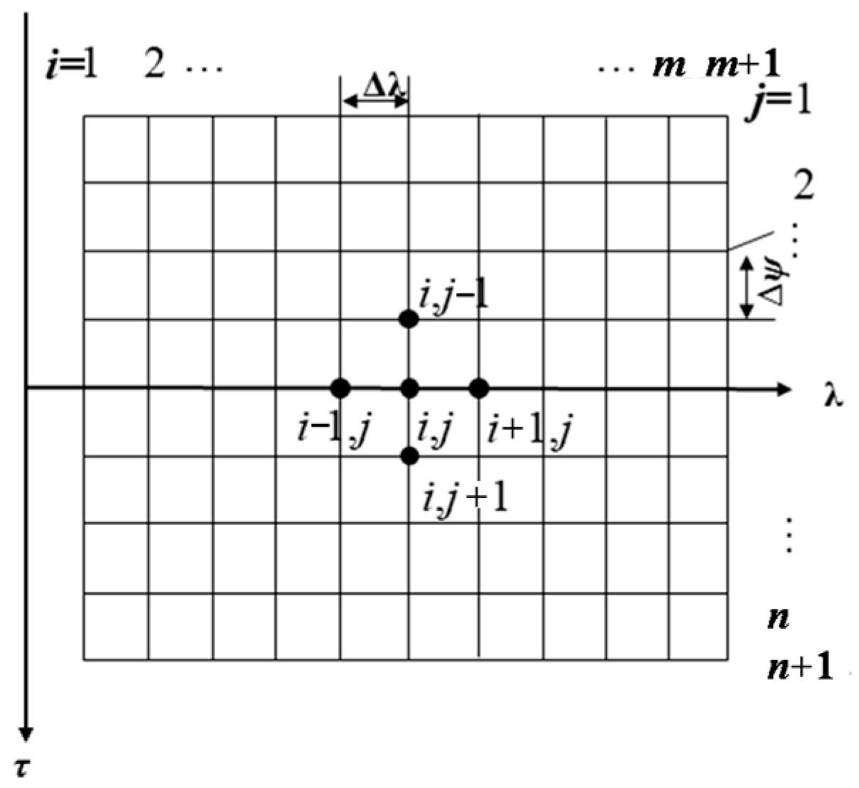
The boundary conditions are the Reynolds boundary conditions [19,28]. In Figure 2, the pressures in columns 1 and (m + 1) are set to 0, which is used as the circumferential starting boundary. The circumferential rupture boundary is realized as follows: the pressure along the circumference is calculated point by point in rows from j = 2 to n, and in columns from i = 2 to m. When the pressure value is negative, it is determined that the water film rupture occurs at this point, and the pressure is set to zero at this point and the points after the row in which it is located. After iterative calculation, the rupture boundary gradually approaches the natural rupture boundary, and the pressure distribution satisfies the Reynolds boundary conditions.
Here, λ is the axial direction coordinate of the bearing; l is the length of the bearing, m; and θf denotes the angular coordinate at the position of natural rupture of the water film, °.
The water film thickness equation [24,26,27,29,30] of micro-groove water-lubricated stern tube bearings is
where δ is the radial deformation of the bearing inner surface nodes; hs is the thickness of the water film when ignoring the bearing deformation and groove, hs = c + ecos(Ψ − θ), c is the radius clearance, e is the eccentricity distance; and Dt is the depth of the micro-groove texture.
The flexibility matrix method [31,32,33] is used to input the meshing, cell numbering etc. into the finite element software ANSYS. The flexibility matrix method explicitly gives the relationship between elastic deformation and pressure distribution, which improves the coupling of the Reynolds equation and elastic deformation. The finite element model of the bearing liner is established in ANSYS, the finite element meshing of the bearing is adopted as a 6-plane cell, and the rectangular mesh of its inner surface is the mesh section required for the differential discrete Reynolds equation. For convenience, this is called the inner surface grid of the bearing and the inner surface cell. The solution of the elastic deformation equation involves calculating the radial deformation of the inner surface of the bearing under normal pressure distribution. For linear elastic materials, the elastic deformation equation can be expressed as
where the subscript “node” represents the number of nodes on the inner surface of the bearing; the subscript “elem” represents the number of elements on the inner surface of the bearing; {δ} is the radial deformation of bearing inner surface nodes; and {p} is the average pressure of the inner surface elements of the bearing, and the pressure of the inner surface nodes is obtained by solving the Reynolds equation. The average pressure of the inner surface elements is the average of the pressures at the nodes of the constituent units; [G] is the flexibility matrix. The physical significance of the jth column vector is the radial deformation of the inner surface node at the inner surface cell j under the action of element pressure distribution.
In generating the flexibility matrix using ANSYS, the mesh size is 3 × 400 × 40, i.e., 3 nodes are taken in the radial direction, n = 400 nodes in the circumferential direction (τ direction), and m = 40 nodes in the axial direction (λ direction). Thus, the differential grid size for the discrete Reynolds equation is 400 × 40.
The equation for calculating the combined water film force is
where Fs is horizontal component of the water film force; Fc is the vertical component of water film force; F is the combined force of the water film force; and Ω is the water film intact zone.
The friction coefficient equation is as follows:
where F1 is the shear flow resistance, N; F2 is the pressure flow resistance, N; FT is the total resistance, N; f is the friction coefficient; Ψ1, Ψ2 are the starting and ending angular coordinates of the bearing, respectively; Ψb is the angular coordinate at the point of water film rupture; hb is the water film thickness at the point of water film rupture; and l is the bearing length, m.
We dimensionalize Equations (1) to (6) and provide dimensionless relative units as follows:
c is the bearing radius clearance, m; R is the bearing radius, m; ϕ is the bearing clearance ratio; ε is eccentricity; η is the viscosity of the lubricant, and when the temperature is 20 °C, η = η0 = 0.001 Pa·s; and l is the bearing length, m.
The dimensionless Reynolds equation for micro-groove water-lubricated stern tube bearings is
The dimensionless equation for the water film thickness of micro-groove water-lubricated stern tube bearings is:
where , .
The equation for the dimensionless water film pressure in the horizontal direction is:
where is the water film completion area.
The equation for the dimensionless water film pressure in the vertical direction is:
The dimensionless water film’s load-carrying capacity equation obtained from Equations (9) and (10) is:
The equation for dimensionless shear flow resistance is:
The equation for dimensionless pressure flow resistance is:
The total resistance equation obtained from Equations (12) and (13) is
The friction coefficient equation obtained from Equations (11) to (14) is
2.1. Discretization of the Reynolds Equation (7)
The finite difference method [34,35,36,37] is used to solve the Reynolds Equation (7) by dividing m mesh cell along the axial direction (λ direction) of the bearing and n mesh cell along the circumferential direction (τ direction) of the bearing; the mesh division is shown in Figure 2.
According to the idea of finite difference method, both and can be expressed by the difference quotient formed by the pressure values on adjacent nodes.
If the values on half a step size are used to form the difference quotient, the results will be more accurate.
The second derivative at any node can be represented by the difference of the first derivative at the insertion point of adjacent half-steps.
Furthermore, the first derivative in Equation (18) is represented by the difference quotient of the corresponding node.
We can obtain the following equation:
Similarly, can also be expressed as
Through the above simplification, the dimensionless Reynolds equation of an incompressible water film with constant temperature, constant viscosity, and normal working conditions can be obtained:
After simplifying, we can obtain the discretized form of the continuous Reynolds Equation (7), as shown below:
The coefficients in Equation (23) are
2.2. Discretization of Elastic Deformation Equation , in Equation (8)
Discretizing the continuous elastic deformation equation yields the following elastic deformation formulation:
2.3. Ultra-Relaxation Iterative Method for Solving Pressure Distribution and Pressure Convergence Conditions
Equation (23) obtained from the discretization is a system of linear algebraic equations, which is solved using the super-relaxed iterative method, calculated as:
where β is the super relaxation factor, 1 < β < 2; k is the number of stress iterations.
Combined with the boundary conditions, the pressure calculation formula can end the iterative calculation after a certain number of iterations to satisfy the following convergence conditions.
ζ is the pressure convergence accuracy, ζ = 1.0 × 10⁻⁴.
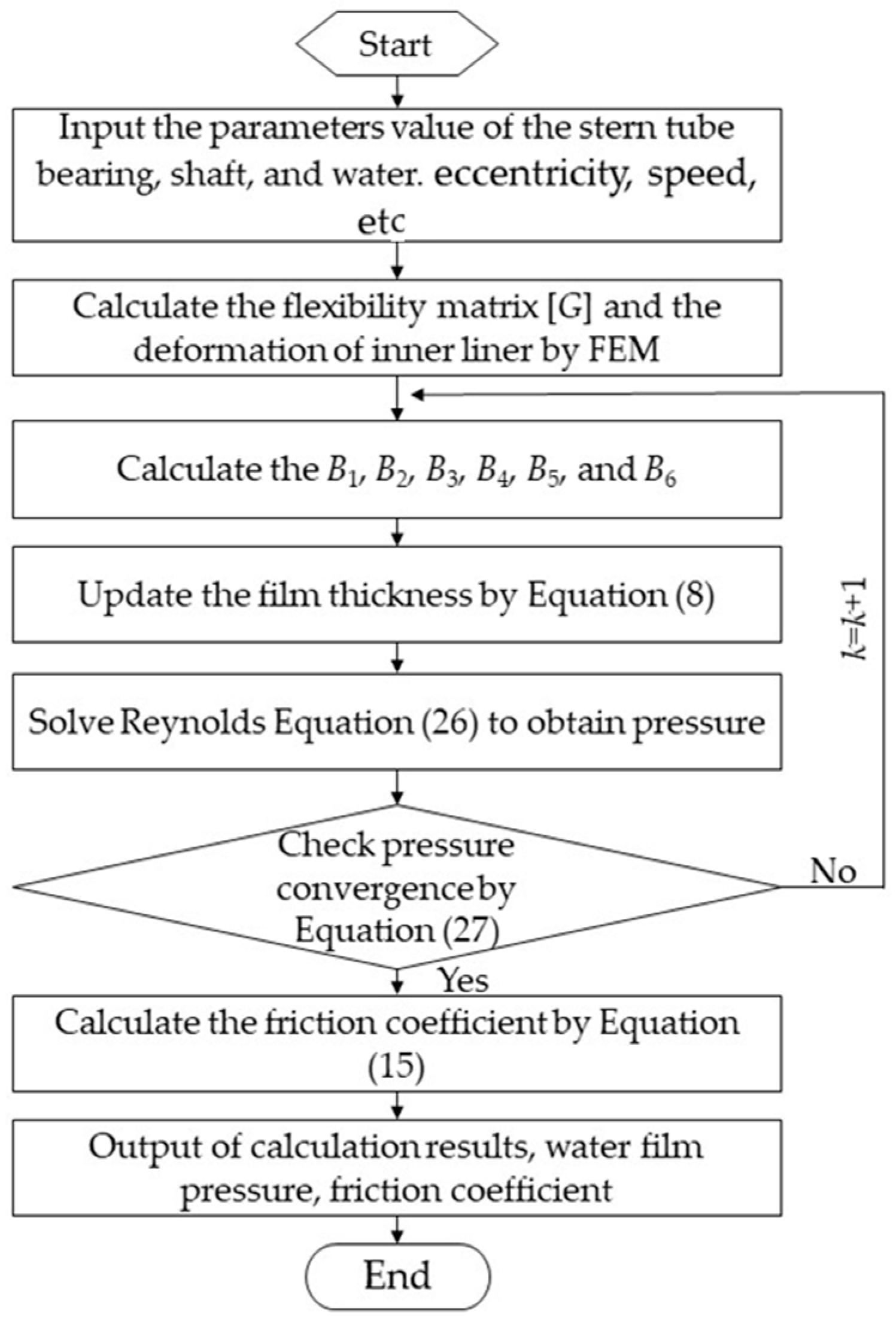
The diagram of calculation process is shown in Figure 3.
3. Experiment
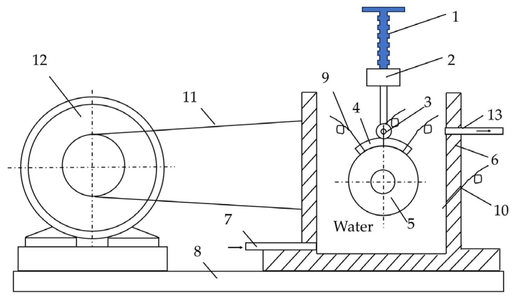
The test was carried out on a JXH-C liquid dynamic sliding bearing test bench, and the schematic diagram of the test bench is shown in Figure 4.
Experimental technique: The power part of the left side of the test bench is a small DC motor, for which the power is 600 W, the rated voltage is 220 V, and the maximum is 3000 r/min. The right side of the test part mainly consists of the test spindle and the two high-precision single-row centripetal ball bearings. The main spindle is equipped with a large pulley, and the pulley side of the belt wheel is equipped with an infrared velocimeter, which is used to measure the rotational speed of the journal. The diameter of the spindle is 60 mm, the length of the spindle is 100 mm, and the speed range of the spindle is 0~1500 r/min. Pressure sensor 9, as shown in Figure 4, uses an HM91A-H1-2-V2-F1-W1 sensor, with a maximum range of 2 MPa and an accuracy of 0.025%. A complete loading device (1, as shown in Figure 4) consisting of a screw loading rod, loading force sensor (2, as shown in Figure 4), and loading rollers (3, as shown in Figure 4) is mounted directly above the spindle. The device changes the size of the loading force through the screw, uses the loading roller to apply the loading force on the slat, and collects the size of the loading force through the loading force sensor. The loading force sensor 2 is a BHR-4 type load cell with a maximum range of 2000 N and an accuracy of 0.1%. The slats are arranged directly above the spindle for ease of loading. In order to simulate the dynamic pressure lubrication of the bearing slats more realistically, the slats should be completely submerged by water. The water in the tank is in a flowing state to ensure a constant water temperature, which is set at 20 °C.
Before the formal test, to ensure that the inner surface of the slat and the surface of the spindle had a better fit, the slat was soaked in water for 24 h, and then the slat was mounted on the test bench to break in for 30 min. After the break-in was completed, the formal test began. During the test, the water film pressure was measured by three pressure sensors on the slat, which were installed in the three round holes shown in Figure 5a.
To verify the correctness of the fluid solid coupling mathematical model of the water-lubricated micro-groove texture stern tube bearing, the lining material of the test strip was Thordon, the elastic modulus was 490 MPa, the density was 3220 kg/m3, and Poisson’s ratio was 0.45. The slab shell was 6061 aluminum alloy. The lining and shell were pasted with epoxy resin. There were two groups of slabs in this experiment: no micro-grooves and local micro-grooves. The shaft diameter was 60 mm, the bearing inner diameter was 60.25 mm, the bearing length was 100 mm, the rectangular groove was a through-type, the span was 0.4 mm, the groove spacing was 2 mm, and the groove depth was 50 μm. The load was 12 N and the speed was 1000 r/min. The local micro-groove lath was a micro-groove with a rectangular cross-section shape uniformly processed from the inlet edge to the circumferential 30° range. The test block with local micro-grooves is shown in Figure 5.
The water film pressure values were measured at 10°, 30°, and 50° positions of the test block, along the circumferential angle direction, three times at each position, and then the average value was taken. The tested average and simulated values are listed in Table 1.
The water film pressure test values of two types of micro-grooved stern tube bearing test blocks were obtained and compared with the simulation values, as shown in Figure 6.
It can be seen from Figure 6 that the simulations of the two types of test blocks without micro-grooves and with local micro-grooves are in good agreement with the experimental water film pressure, thus verifying the correctness of the numerical results.
4. Results and Discussion
4.1. Effect of Groove Ratio
The groove ratio is the ratio of the area of the grooves to the area of the bearing lining. From the above experiments and simulations, the size of the groove area has a certain effect on the bearing load-carrying capacity. Therefore, we designed three kinds of through-type grooves with different cross-sectional shapes: rectangle, circle, and isosceles triangle. The shapes of the designed groove sections are shown in Figure 1. The geometric parameters of the groove were Wt = 0.4 mm, Dt = 0.05 mm, and Pt = 2 mm. The speed was 1000 r/min, and the eccentricity ε was 0.3. The groove ratio was set to 0, 0.25, 0.50, 0.75, and 1.00. The dimensionless bearing load-carrying capacity , Equation (11), and friction coefficient , Equation (15), of the stern tube bearings were calculated, as shown in Figure 7.
Figure 7 illustrates that the bearing load-carrying capacity of rectangular, circular, and isosceles triangular groove stern tube bearings increases nonlinearly with the groove ratio and reaches its maximum at around 0.25 before decreasing. At a groove ratio of 0.25, micro-grooves are positioned on the water inlet side of the minimum water film thickness of the stern tube bearing. During shaft rotation, water is drawn into the bearing gap, and the micro-grooves undergo micro deformation under load. This results in the formation of the water sac effect in the internal space of the micro-grooves, further increasing the hydrodynamic force and enhancing the bearing load-carrying capacity of the stern tube bearing. However, if the groove ratio exceeds 0.25, as the number of micro-grooves increases, the grooves will act badly on the water film, resulting in a thicker water film thickness in the groove region, which in turn causes a reduction in the water film pressure, leading to a reduction in the load-bearing capacity. The friction coefficient is inversely proportional to the bearing load-carrying capacity of the stern tube bearing, as shown in Equation (11). As the groove ratio increases, the friction coefficient decreases first and then increases nonlinearly. Comparing the load-carrying capacity and friction coefficient curves of the three different cross-sectional groove stern tube bearings, the rectangular groove texture stern tube bearing exhibits superior bearing load-carrying capacity and friction performance when the groove ratio is less than or equal to 0.25. When the groove ratio is greater than 0.25, the isosceles triangular groove texture stern tube bearing demonstrates better bearing load-carrying capacity and friction performance than the other two types.
To determine the optimal value for the local micro groove ratio, stern tube bearings with rectangular, circular, and isosceles triangular groove textures were selected with the target of achieving a maximum bearing load-carrying capacity and minimum friction coefficient. The speed was 1000 r/min and the eccentricity ε was 0.3. The calculation was carried out within the groove ratio range 0.20 to 0.35. Figure 8 shows the results obtained.
At a groove ratio of around 0.31, the rectangular groove stern tube bearing achieves its maximum bearing load-carrying capacity and minimum friction coefficient. To obtain optimal lubrication performance, especially with Thordon-lined water-lubricated stern tube bearings, a groove ratio of 0.30 to 0.32 is recommended. Isosceles triangular groove stern tube bearings outperform circular and rectangular groove stern tube bearings in terms of the bearing load-carrying capacity and friction coefficient at groove ratios above 0.31.
4.2. Effect of Groove Width
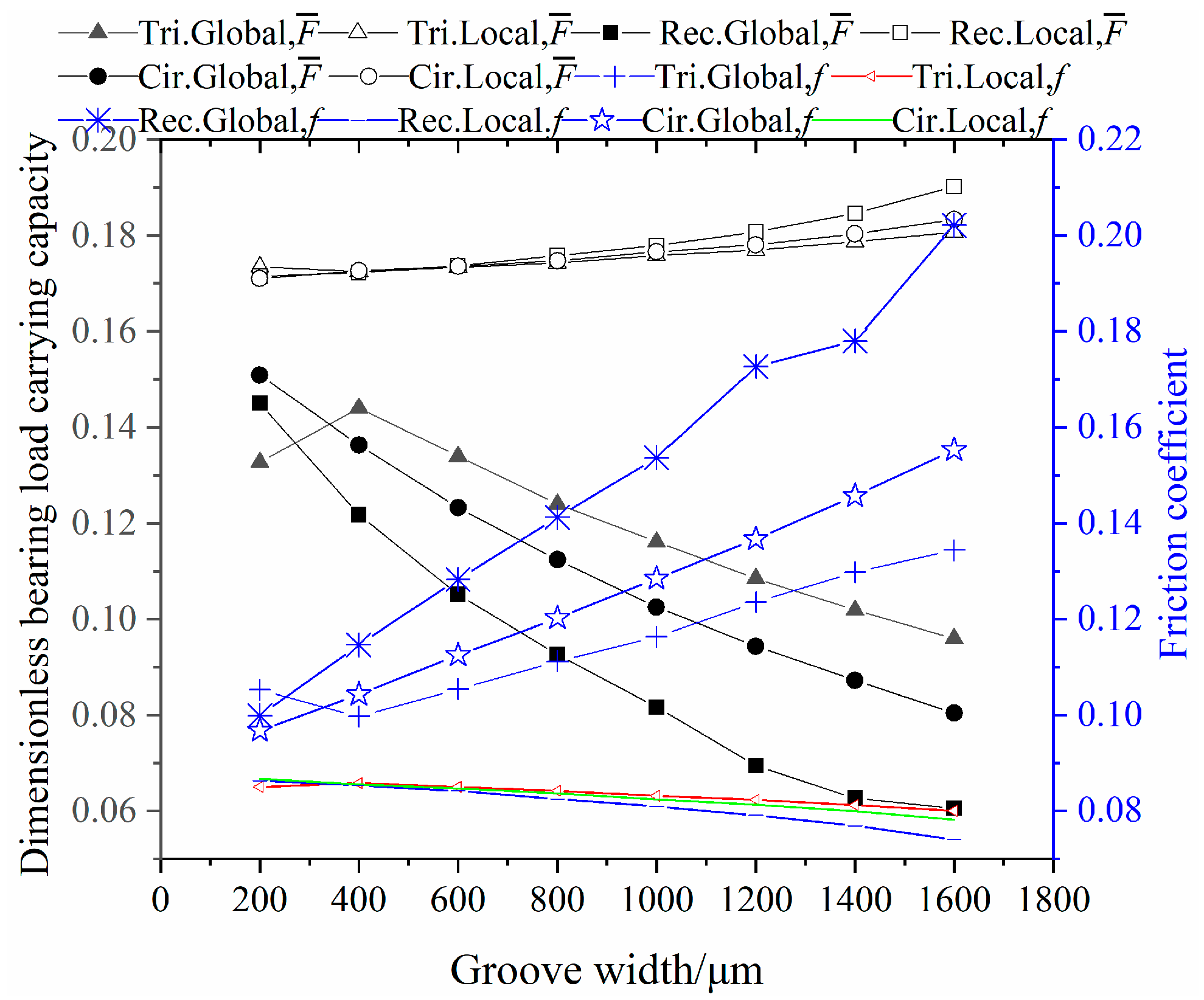
To investigate the effect of the groove width on the bearing load-carrying capacity and friction coefficient of stern tube bearings, we selected rectangular, circular, and isosceles triangular micro-groove stern tube bearings. The local groove ratio was fixed at 0.31, and the global groove ratio was set to 1.00. The groove dimensions were Dt = 0.05 mm and Pt = 2 mm, and the bearings were tested at a speed of 1000 r/min with eccentricity ε of 0.3. We varied the value of Wt from 200 to 1600 μm in intervals of 200 μm. The resulting calculations are presented in Figure 9.
As can be seen from Figure 9, under the same conditions, the bearing load-carrying capacity of the local micro-groove stern tube bearing test block is greater than that of the global micro-groove stern tube bearing test block. The reason for this is that the location of the local micro-groove is on the inlet side of the minimum water film thickness, which makes it easy to form the water sac effect and helps to increase the bearing load-carrying capacity. The global micro-groove stern tube bearing’s groove position across the domain of the minimum water film thickness on both sides (that is, the inlet side and the outlet side; although a water bladder effect is formed on the inlet side, the thickness of the water film on the outlet side is thickened, resulting in a lower pressure on the water film on the outlet side) results in the bearing load-carrying capacity being less than that of the local micro-groove stern tube bearing.
Comparing the water-lubricated stern tube bearing blocks with local micro-groove and global micro-grooves, the bearing load-carrying capacity of the local micro-groove and global micro-groove water-lubricated stern tube bearing blocks showed a nonlinear increase and a fractional linear decrease with the increase in the width of the micro-groove, respectively. This phenomenon is due to the location of the micro-groove. The groove of the local micro-groove water-lubricated stern tube bearing is on the water inlet side of the minimum water film thickness, and as the width of the micro-groove increases, a larger water sac is formed in the groove, and the larger water sac helps to increase the bearing load-carrying capacity of the water-lubricated stern tube bearing. The grooves of the global micro-groove water-lubricated stern tube bearing are not only distributed on the inlet side of the minimum water film thickness but also on the outlet side. As the width of the groove increases, the load-carrying capacity of the global micro-groove water-lubricated stern tube bearing increases on the inlet side, but the load-carrying capacity decreases due to the thickening of the water film thickness of the global micro-groove water lubricated stern tube bearings on the outlet side results in a lower water film pressure, and the decrease in the load-carrying capacity on the outlet side is greater than the increase in the load-carrying capacity on the inlet side as the width of the groove increases.
The dimensionless bearing load-carrying capacity of both global and local isosceles triangular micro-groove stern tube bearings first increases and then decreases nonlinearly with an increase in groove width. Similarly, the friction coefficient decreases first and then increases nonlinearly. For global and local rectangular groove stern tube bearings, the dimensionless bearing load-carrying capacity exhibits a nonlinear decreasing and increasing trend with the increase in groove width, while the friction coefficient shows a nonlinear increasing and decreasing trend. Moreover, the dimensionless bearing load-carrying capacity of global and local circular groove stern tube bearings shows a non-linear decreasing and non-linear increasing trend with an increase in groove width, and the friction coefficient exhibits a non-linear increasing and non-linear decreasing trend. Overall, the lubrication performance of the local rectangular groove stern tube bearing is superior to that of the isosceles triangle and circular groove stern tube bearings.
Under identical conditions, the bearing load-carrying capacity and friction performance of local groove stern tube bearings are significantly superior to those of global groove stern tube bearings. At a groove width of 1600 μm, the local rectangular groove stern tube bearing exhibits a 217% increase in dimensionless bearing load-carrying capacity compared to the global rectangular groove stern tube bearing (i.e., |0.19 − 0.06|/0.06 × 100%), while the friction coefficient decreases by 65% (i.e., |0.20 − 0.07|/0.20 × 100%). With the increase in groove width, the lubrication effect of the local rectangular groove water-lubricated stern tube bearing outperforms the other two types.
5. Conclusions
- (1)
- Reasonably arranging the groove ratio is beneficial for improving the lubrication effect of water-lubricated stern tube bearings. Rectangular groove stern tube bearings exhibit superior bearing load-carrying capacity and friction coefficient performance compared to circular and isosceles triangular micro-groove stern tube bearings when the groove ratio is between 0.30 and 0.32, resulting in the best lubrication performance. Isosceles triangular groove stern tube bearings exhibit better bearing load-carrying capacity and friction coefficient performance than the other two types when the groove ratio is above 0.31.
- (2)
- Increasing the width of the groove results in a significantly better lubrication effect of the local rectangular groove stern tube bearing compared to other stern bearings. The dimensionless bearing load-carrying capacity can be increased by 217%, and the friction coefficient can be reduced by 65%.
6. Further Research
In this study, we focused on investigating the water-lubricated stern tube bearing made of Thordon material as the research subject. We aimed to explore the impact of microscopic surface groove structures on the lubrication performance of water-lubricated stern tube bearings. The selection of lining materials for water-lubricated stern tube bearings is not restricted to Thordon material alone. Other options, such as NBR, phenol, ACM, SF, and iron pearwood, can also be utilized as linings for water-lubricated stern tube bearings.
Materials such as Thordon, phenol, ACM, SF, and iron pearwood exhibit high hardness. Thus, when they are employed as liners for water-lubricated stern tube bearings, it becomes more convenient to incorporate micro-grooves into the inner surface of the liner. However, the task of creating micro-grooves in rubber-based linings poses a significant challenge due to the low hardness and susceptibility to deformation under force. This characteristic greatly complicates the process of machining micro-grooves. In practical operations, the geometry of micro-grooves becomes difficult to maintain due to the extrusion and deformation of the rubber-based liner, resulting in substantial distortions of the micro-groove shape. Consequently, researchers are interested in investigating the lubrication characteristics of water-lubricated stern tube bearings equipped with micro-grooves. To facilitate their study, we recommend that scholars opt for materials with higher hardness.
Funding
This research was funded by Jiangxi Provincial Department of Science and Technology, grant number No. 20192BBEL50028, and the Jining University’s “Hundred Outstanding Talents” Support Program Cultivation Project, and the APC was funded by No. 20192BBEL50028.
Data Availability Statement
Data sharing is not applicable to this article.
Acknowledgments
This work is supported by the Jiangxi Provincial Department of Science and Technology (No. 20192BBEL50028) and the Jining University’s “Hundred Outstanding Talents” Support Program Cultivation Project.
Conflicts of Interest
The author declares no conflict of interest. The funders had no role in the design of the study, in the collection, analyses, or interpretation of data, in the writing of the manuscript, or in the decision to publish the results.
Nomenclature
| c | bearing radius clearance |
| Dt | depth of the micro-grooves |
| e | eccentricity distance |
| “elem” | the number of elements on the inner surface of the bearing |
| f | friction coefficient |
| F | combined force of the water film force |
| dimensionless bearing load-carrying capacity | |
| F1 | shear flow resistance |
| F2 | pressure flow resistance |
| Fc | vertical component of water film force |
| Fs | horizontal component of the water film force |
| Ft | radial load applied on the spindle |
| FT | total resistance |
| [G] | flexibility matrix |
| h | water film thickness |
| hb | water film thickness at the point of water film rupture |
| hmin | minimum film thickness |
| hmax | maximum film thickness |
| hs | thickness of the water film when ignoring the bearing deformation and groove |
| k | number of stress iterations |
| l | bearing length |
| “node” | the number of nodes on the inner surface of the bearing |
| O1 | centers of the bearing |
| O2 | centers of the shaft |
| p | water film pressure |
| Pt | span of the micro-grooves |
| {p} | average pressure of the inner surface elements of the bearing |
| r | radius of the shaft |
| R | inner radius of the bearing |
| Wt | width of the micro-grooves |
| β | super relaxation factor |
| γ | circumferential arrangement range of the micro-groove area |
| δ | radial deformation of the bearing inner surface nodes |
| {δ} | radial deformation of bearing inner surface nodes |
| ε | eccentricity ratio |
| ζ | pressure convergence accuracy |
| η | viscosity of the water |
| θ | attitude angle |
| θf | angular coordinate at the position of natural rupture of the water film |
| λ | axial direction coordinate of bearing |
| φ | circumferential coordinate starting from the maximum film thickness |
| ω | rotational speed of shaft |
References
- Prajapati, D.K.; Ramkumar, P. Surface topography effect on tribological performance of water-lubricated journal bearing under mixed-EHL regime. Surf. Topogr. Metrol. Prop. 2022, 10, 045022. [Google Scholar] [CrossRef]
- Chen, J.; Guo, Z.; Li, X.; Yuan, C. Development of gradient structural composite for improving tribological performance of PU material in water-lubricated bearings. Tribol. Int. 2022, 176, 107876. [Google Scholar] [CrossRef]
- Lv, F.; Jiao, C.; Xu, J. Theoretical and experimental investigation on effective length-to-diameter ratio of misaligned water-lubricated bearings. Tribol. Int. 2023, 187, 108712. [Google Scholar] [CrossRef]
- Xiang, G.; Wang, J.; Han, Y.; Yang, T.; Dai, H.; Yao, B.; Zhou, C.; Wang, L. Investigation on the nonlinear dynamic behaviors of water-lubricated bearings considering mixed thermoelastohydrodynamic performances. Mech. Syst. Signal Process. 2021, 169, 108627. [Google Scholar] [CrossRef]
- Hanawa, N.; Kuniyoshi, M.; Miyatake, M.; Yoshimoto, S. Static characteristics of a water-lubricated hydrostatic thrust bearing with a porous land region and a capillary restrictor. Precis. Eng. 2017, 50, 293–307. [Google Scholar] [CrossRef]
- Wu, Z.; Guo, Z.; Yuan, C. Insight into water lubrication performance of polyetheretherketone. J. Appl. Polym. Sci. 2020, 138, 49701. [Google Scholar] [CrossRef]
- Hamilton, D.B.; Walowit, J.A.; Allen, C.M. A Theory of Lubrication by Microirregularities. J. Basic Eng. 1966, 88, 177–185. [Google Scholar] [CrossRef]
- Etsion, I.; Burstein, L. A Model for Mechanical Seals with Regular Microsurface Structure. Tribol. Trans. 1996, 39, 677–683. [Google Scholar] [CrossRef]
- Tala-Ighil, N.; Fillon, M. A numerical investigation of both thermal and texturing surface effects on the journal bearings static characteristics. Tribol. Int. 2015, 90, 228–239. [Google Scholar] [CrossRef]
- Tala-Ighil, N.; Fillon, M.; Maspeyrot, P. Effect of textured area on the performances of a hydrodynamic journal bearing. Tribol. Int. 2011, 44, 211–219. [Google Scholar] [CrossRef]
- Choudhury, D.; Rebenda, D.; Sasaki, S.; Hekrle, P.; Vrbka, M.; Zou, M. Enhanced lubricant film formation through micro-dimpled hard-on-hard artificial hip joint: An in-situ observation of dimple shape effects. J. Mech. Behav. Biomed. Mater. 2018, 81, 120–129. [Google Scholar] [CrossRef]
- Shinde, A.; Pawar, P.; Shaikh, P.; Wangikar, S.; Salunkhe, S.; Dhamgaye, V. Experimental and numerical analysis of conical shape hydrodynamic journal bering with partial texturing. Procedia Manuf. 2018, 20, 300–310. [Google Scholar] [CrossRef]
- Dong, N.; Wang, Y.Q.; Liu, Q.; Huang, X.B. Influence of Micro-Morphology on Thermal Elatohydrodynamic Lubrication of Water-Lubricated Tenmat Bearing. Appl. Mech. Mater. 2015, 743, 85–90. [Google Scholar] [CrossRef]
- Wang, Y. Thermal Elastohydrodynamic Lubrication Property Analysis of Water-lubricated Tenmat Bearing Considering Debris and Surface Roughness. J. Mech. Eng. 2017, 53, 121–129. [Google Scholar] [CrossRef]
- He, Z.; Song, Q.; Liu, Q.; Xin, J.; Yang, C.; Liu, M.; Li, B.; Yan, F. Analysis of the effect of texturing parameters on the static characteristics of radial rigid bore aerodynamic journal bearings. Surf. Topogr. Metrol. Prop. 2022, 10, 035025. [Google Scholar] [CrossRef]
- Blatter, A.; Maillat, M.; Pimenov, S.; Shafeev, G.; Simakin, A.; Loubnin, E. Lubricated sliding performance of laser-patterned sapphire. Wear 1999, 232, 226–230. [Google Scholar] [CrossRef]
- Yuan, S.; Huang, W.; Wang, X. Orientation effects of micro-grooves on sliding surfaces. Tribol. Int. 2011, 44, 1047–1054. [Google Scholar] [CrossRef]
- A Wahab, J.; Ghazali, M.; Sajuri, Z.; Otsuka, Y.; Jayaprakash, M.; Nakamura, S.; Baharin, A. Effects of micro-grooves on tribological behaviour of plasma-sprayed alumina-13%titania coatings. Ceram. Int. 2017, 43, 6410–6416. [Google Scholar] [CrossRef]
- Ali, F.; Kaneta, M.; Křupka, I.; Hartl, M. Experimental and numerical investigation on the behavior of transverse limited micro-grooves in EHL point contacts. Tribol. Int. 2015, 84, 81–89. [Google Scholar] [CrossRef]
- Ehret, P.; Dowson, D.; Taylor, C. Waviness Orientation in EHL Point Contact. In Tribology Series; Elsevier: Amsterdam, The Netherlands, 1996; Volume 31, pp. 235–244. [Google Scholar] [CrossRef]
- Thakre, G.D.; Sharma, S.C.; Harsha, S.; Tyagi, M. A theoretical study of ionic liquid lubricated μ-EHL line contacts considering surface texture. Tribol. Int. 2016, 94, 39–51. [Google Scholar] [CrossRef]
- Kaneta, M.; Guo, F.; Wang, J.; Krupka, I.; Hartl, M. Formation of micro-grooves under impact loading in elliptical contacts with surface ridges. Tribol. Int. 2013, 65, 336–345. [Google Scholar] [CrossRef]
- Shi, X.; Ni, T. Effects of groove textures on fully lubricated sliding with cavitation. Tribol. Int. 2011, 44, 2022–2028. [Google Scholar] [CrossRef]
- Gong, J.; Jin, Y.; Liu, Z.; Jiang, H.; Xiao, M. Study on influencing factors of lubrication performance of water-lubricated micro-groove bearing. Tribol. Int. 2018, 129, 390–397. [Google Scholar] [CrossRef]
- Wu, Z.; Yuan, C.; Guo, Z.; Huang, Q. Effect of the groove parameters on the lubricating performance of the water-lubricated bearing under low speed. Wear 2023, 522, 204708. [Google Scholar] [CrossRef]
- Meng, F.; Chen, Y. Analysis of elasto-hydrodynamic lubrication of journal bearing based on different numerical methods. Ind. Lubr. Tribol. 2015, 67, 486–497. [Google Scholar] [CrossRef]
- Su, B.; Huang, L.; Huang, W.; Wang, X. The load carrying capacity of textured sliding bearings with elastic deformation. Tribol. Int. 2017, 109, 86–96. [Google Scholar] [CrossRef]
- Liu, S. On boundary conditions in lubrication with one dimensional analytical solutions. Tribol. Int. 2012, 48, 182–190. [Google Scholar] [CrossRef]
- Du, Y.; Li, M. Effects on lubrication characteristics of water-lubricated rubber bearings with journal tilting and surface roughness. Proc. Inst. Mech. Eng. Part J J. Eng. Tribol. 2019, 234, 161–171. [Google Scholar] [CrossRef]
- Xie, Z.; Liu, H. Experimental research on the interface lubrication regimes transition of water lubricated bearing. Mech. Syst. Signal Process. 2020, 136, 106522. [Google Scholar] [CrossRef]
- Chen, C.; Lin, G.; Hu, Z. An innovative and efficient solution for axisymmetric contact problem between structure and half-space. Eng. Anal. Bound. Elements 2022, 142, 10–27. [Google Scholar] [CrossRef]
- Liu, H.; Wu, B.; Li, Z. The generalized flexibility matrix method for structural damage detection with incomplete mode shape data. Inverse Probl. Sci. Eng. 2021, 29, 2019–2039. [Google Scholar] [CrossRef]
- Mukhopadhyay, M.; Sheikh, A.H. The Flexibility Matrix Method; Springer International Publishing: Cham, Switzerland, 2022; pp. 133–148. [Google Scholar] [CrossRef]
- Rekha, J.; Suma, S.P.; Shilpa, B.; Khan, U.; Hussain, S.M.; Zaib, A.; Galal, A.M. Solute transport exponentially varies with time in an unsaturated zone using finite element and finite difference method. Int. J. Mod. Phys. B 2022, 37, 2350089. [Google Scholar] [CrossRef]
- Liu, G.; Li, M. Lubrication Characteristics of Water-Lubricated Rubber Bearings Based on an Improved Algorithm of the Mass Conservation Boundary Condition. J. Tribol. 2022, 144, 081804. [Google Scholar] [CrossRef]
- Du, Y.; Quan, H. Characteristics of water-lubricated rubber bearings in mixed-flow lubrication state. Lubr. Sci. 2022, 34, 224–234. [Google Scholar] [CrossRef]
- Prajapati, D.K.; Katiyar, J.K.; Prakash, C. Determination of friction coefficient for water-lubricated journal bearing considering rough surface EHL contacts. Int. J. Interact. Des. Manuf. 2023, 1–9. [Google Scholar] [CrossRef]
Figure 1.
Lubrication model of micro-groove stern tube bearing. (a) Schematic diagram of micro-groove stern tube bearing structure; (b) rectangular structure of micro-grooves; (c) triangle structure of micro-grooves; (d) semi-circular structure of micro-grooves. Adapted from [15].
Figure 1.
Lubrication model of micro-groove stern tube bearing. (a) Schematic diagram of micro-groove stern tube bearing structure; (b) rectangular structure of micro-grooves; (c) triangle structure of micro-grooves; (d) semi-circular structure of micro-grooves. Adapted from [15].

Figure 2.
Grid division.

Figure 3.
Diagram of calculation process.

Figure 4.
Test bench schematic: 1. screw for loading; 2. sensor for measuring loading force; 3. roller for loading; 4. test plate material to be tested; 5. shaft; 6. water tank; 7, 13. water hole; 8. base; 9. pressure sensor; 10. temperature sensor; 11. belt; 12. motor.
Figure 4.
Test bench schematic: 1. screw for loading; 2. sensor for measuring loading force; 3. roller for loading; 4. test plate material to be tested; 5. shaft; 6. water tank; 7, 13. water hole; 8. base; 9. pressure sensor; 10. temperature sensor; 11. belt; 12. motor.

Figure 5.
Test block with local micro-grooves: (a) image of the object; (b) schematic diagram.

Figure 6.
Tested and simulated pressure values of water film.

Figure 7.
Effect of groove ratio on dimensional bearing load-carrying capacity , and friction coefficient of stern tube bearing.
Figure 7.
Effect of groove ratio on dimensional bearing load-carrying capacity , and friction coefficient of stern tube bearing.

Figure 8.
The dimensionless bearing load-carrying capacity and friction coefficient of the stern tube bearing as the groove ratio ranges from 0.20 to 0.35.
Figure 8.
The dimensionless bearing load-carrying capacity and friction coefficient of the stern tube bearing as the groove ratio ranges from 0.20 to 0.35.

Figure 9.
Effect of groove width on bearing load-carrying capacity and friction coefficient of stern tube Bearing. Tri. represents triangular; Rec. represents rectangular; Cir. represents circular; Global represents stern tube bearing with a triangular micro-groove ratio of 1.0; Local represents stern tube bearing with a triangular micro-groove ratio of 0.31; represents the dimensionless bearing load-carrying capacity; and f represents the friction coefficient.


Table 1.
The water film pressure values of blocks.
| Without Grooves | Local Grooves | |||||
|---|---|---|---|---|---|---|
| Angle/° | Simulation/kPa | Test/kPa | Relative Error | Simulation/kPa | Test/kPa | Relative Error |
| 10 | 0.02401 | 0.02423 | 0.91% | 0.02466 | 0.02489 | 0.92% |
| 30 | 0.06388 | 0.06423 | 5.44% | 0.06411 | 0.06492 | 1.25% |
| 50 | 0.01839 | 0.01856 | 0.92% | 0.01872 | 0.01889 | 0.89% |
Disclaimer/Publisher’s Note: The statements, opinions and data contained in all publications are solely those of the individual author(s) and contributor(s) and not of MDPI and/or the editor(s). MDPI and/or the editor(s) disclaim responsibility for any injury to people or property resulting from any ideas, methods, instructions or products referred to in the content. |
© 2023 by the author. Licensee MDPI, Basel, Switzerland. This article is an open access article distributed under the terms and conditions of the Creative Commons Attribution (CC BY) license (https://creativecommons.org/licenses/by/4.0/).
Share and Cite
MDPI and ACS Style
Zhang, S. Effect of Groove Structure on Lubrication Performance of Water-Lubricated Stern Tube Bearings. Lubricants 2023, 11, 374. https://doi.org/10.3390/lubricants11090374
AMA Style
Zhang S. Effect of Groove Structure on Lubrication Performance of Water-Lubricated Stern Tube Bearings. Lubricants. 2023; 11(9):374. https://doi.org/10.3390/lubricants11090374
Chicago/Turabian StyleZhang, Shengdong. 2023. "Effect of Groove Structure on Lubrication Performance of Water-Lubricated Stern Tube Bearings" Lubricants 11, no. 9: 374. https://doi.org/10.3390/lubricants11090374
Note that from the first issue of 2016, this journal uses article numbers instead of page numbers. See further details here.