Article

Finite Element Analysis of the Influence of the Assembly Parameters on the Fretting Phenomena at the Bearing/Big End Interface in High-Performance Connecting Rods

Engineering Department “Enzo Ferrari”, University of Modena and Reggio Emilia, Via Vivarelli 10, 41125 Modena, Italy
*
Author to whom correspondence should be addressed.
Lubricants 2023, 11(9), 375; https://doi.org/10.3390/lubricants11090375
Submission received: 4 August 2023 / Revised: 30 August 2023 / Accepted: 1 September 2023 / Published: 5 September 2023
(This article belongs to the Special Issue Fretting Fatigue in Mechanical Joints)

Abstract

:
Fretting fatigue is a well-known and dangerous damage mode that occurs on the mating surfaces of mechanical components, mainly promoted by a combination of stress distribution, contact pressure distribution, and relative sliding (micro)motion between the surfaces. However, predicting this mechanism is challenging, necessitating specific studies for each assembly due to variable influences. This article presents a methodology for evaluating fretting fatigue damage at the contact between a titanium connecting rod big end and the bearing, adopting the Ruiz parameter as a quantifying damage index. For this purpose, a thermal-structural finite element model is prepared. In particular, the machining and assembly of the split conrod big end are simulated, considering thermal effects. A full engine cycle is first simulated, and results are used for identifying critical instants to be considered for accurate yet computationally efficient calculations. The dependence of fretting fatigue on three factors is studied: bearing crush, bolts tightening torque, and friction coefficient between the big end and the bearing. In summary, the damage increases with a higher crush and friction, while tightening torque has marginal effects. Following a 20% increase in crush height, a corresponding 10% rise in the Ruiz parameter is observed. Conversely, reducing the crush height by 20% leads to an approximately 8% decrease in the Ruiz parameter. When the influence of the bolt preload is taken into account, only a marginal 1% increase of the Ruiz parameter is recorded despite a 30% rise in preload. Evaluating the impact of the friction coefficient on the Ruiz parameter reveals an almost linear relationship. These findings suggest that adjusting the screw preload can enhance the hydrodynamic behavior of the bearing without exacerbating fretting. Furthermore, exploiting the linear correlation between Ruiz and the friction coefficient allows for the generalization of results obtained with specific coefficient values. This methodology can, therefore, serve as a valuable reference for adjusting different variables during the initial design phases of a four-stroke internal combustion engine’s dismountable connecting rod.

1. Introduction

Different fractures found in the big ends of dismountable connecting rods for four-stroke internal combustion engines cannot be justified solely by the stresses registered in the areas where the failure occurred [1]. Many of these fractures can indeed be justified by considering the contribution given by fretting fatigue [2,3,4].
Fretting fatigue is a damage mechanism caused by the combined effects of two distinct factors, i.e., mechanical fatigue and fretting, which can promote and accelerate the failure of the component [5,6,7,8]. On the one hand, mechanical fatigue has been extensively studied in the literature, particularly concerning metallic materials [9,10]. On the other hand, fretting refers to surface damage resulting from friction between two mechanical components. This surface damage promotes the initiation of nucleation points, possibly accelerating the mechanical fatigue failure [11,12]. In the context described, this specific form of fatigue is referred to as fretting fatigue. Predicting these fractures is as important as it is complex. It is necessary to combine surface damage with the stress state of the component under examination. The finite element method (FEM) becomes a valuable tool for forecasting this type of failure [13,14,15,16]. Among the various quantitative indexes for identifying fretting fatigue, the Ruiz parameter (Equation (1)) has been chosen as the selected approach because it can provide valuable insights into the tribological behavior of the components [17]:
R u i z   p a r a m e t e r = ( σ m a x σ m i n ) · W w .
Ruiz understood that the failure of components subject to fretting depends on two main aspects: the stress state of the component under examination, particularly the amplitude of the stress parallel to the mating surfaces (σmaxσmin), and the specific wear work generated at the interface (WW).
While the stress state can be easily determined through the use of FEM, defining the specific wear work requires further investigation. The specific wear work can be defined as the friction coefficient (μ) multiplied by the contact pressure (p) multiplied by the relative displacement (δ) between the two contacting surfaces:
W w = μ · p · δ
Once again, FEM proves to be an effective ally in calculating the contact pressure and relative displacement between the various components under examination [18,19]. From these formulas, it can be stated that it is difficult to give a general significance to numerical studies on fretting fatigue. In fact, each case must be evaluated in a detailed manner. For instance, Le Falher et al. [20] studied the effect of fretting fatigue on shrink-fit lug-bush assemblies. While the component involved resembled the geometry of a connecting rod, the differences in geometric details, materials, and loading conditions made the analyses conducted by Le Fahler et al. not directly applicable to other cases of interest. Some researchers, like Chao [21] and Pujatti et al. [22], analyzed failures caused by fretting fatigue but did not attempt to formulate a numerical methodology capable of predicting them. Others, such as Son et al. [23] and Badding et al. [24], focused on different regions of the connecting rods, leading to non-generalizable conclusions. Others, still, such as Merritt et al. [25], studied connecting rod big ends and adopted a simplified approach limited by computational resources available at the time, resulting in outcomes that could be further enhanced.
In the present contribution, a numerical methodology is explained for calculating the Ruiz parameter on the contact surface between the connecting rod big end and the bearing for a high-performance internal combustion engine.
The paper is organized as follows. Firstly, a brief description of the components considered in the FEM analysis is provided. Subsequently, the assembly procedure and its numerical simulation are described. The FEM calculation setup is then explained, focusing on evaluating the specific wear work between the connecting rod big end and the bearing and, consequently, the Ruiz parameter. Initially, a thorough simulation of the entire engine cycle is performed. However, it is found that it is possible to choose and simulate only selected significative instants (ten in this case) without sacrificing result accuracy while significantly reducing computation time and file size. Once a simplified procedure for evaluating the Ruiz parameter is obtained, the influence of several parameters on the fretting fatigue damage of the connecting rod bearing is studied. Specifically, three different values of the circumferential crush of the bearing, two different tightening torques of the bolts, and four different coefficients of friction are investigated. Finally, some conclusions end the paper.

2. Materials and Methods

2.1. The Assembly Considered in the Analysis

Figure 1a depicts the model of the assembly considered in the analysis, and Figure 1b details the reference system adopted for all the analyses performed using the shell angle θ and the angular speed ω. The dismountable connecting rod, the two tightening bolts, and the big end bearing can be seen. In particular, the connecting rod is made of titanium, the bolts are made of steel, and the bearing is made of steel with a thin coating on the inner surface (see Table 1 for the main mechanical and physical properties of the materials) [26]. Figure 2 shows and defines the bearing crush, i.e., the circumferential (small) over-extent of each half-bearing, which represents an important geometric characteristic of the bearing. When the connecting rod is tightened, the crush is inevitably recovered, and the bearing is compressed and press-fitted into the big end of the connecting rod. Crush values affect the fretting fatigue behavior of the big end. In fact, it directly influences the contact pressure at the interface and, consequently, the possibility of sliding and the relative displacement between the surfaces, which are the main parameters for the determination of the wear work generated at the interface.

2.2. The Assembly Procedure

The assembly procedure of a dismountable connecting rod for a four-stroke internal combustion engine follows several well-defined steps. It is vital to replicate this procedure in the FEM analyses to obtain reliable results.
At the beginning of the procedure, the rod shank and cap are connected by tightening the two bolts. This initial step deforms the big end, causing it to lose its perfectly cylindrical shape. However, the bearing should be mounted on a perfectly cylindrical surface to function optimally. For this reason, the inner surface of the tightened connecting rod is machined to restore the perfect cylindrical shape of the big end. Finally, when it is mounted on the crank pin of the crankshaft, the conrod is disassembled, the bearing is inserted, and it is usually re-tightened with the same preload as before.
Upon reexamining this standard procedure, two noticeable aspects can be discussed. Firstly, the tightening force applied to the bolts deforms the rod differently depending on whether the bearing is installed or not. To achieve the perfect cylindrical shape of the big end even after the bearing is inserted, the preload of the bolts should be appropriately increased. Secondly, when different materials are used for the manufacturing of the conrod and bolts, i.e., titanium for the conrod and steel for the bolts, such as in this case, considering the two different thermal expansion coefficients of the two materials and the operating temperature of the big end typically around 120 °C, the bolt preload should be modified with respect to the assembly stage.
These aspects are analyzed in the following to evaluate the possible variation of the Ruiz parameter. Specifically, the effect of two bolt preloads is studied when the bearing is inserted: the standard value and an increased value estimated to compensate for the thermal effects.

2.3. The Finite Element Model

The FEM model consisted of about 1,807,000 elements. The commercial software Altair Hypermesh 2022.2 was used for the discretization process, while the commercial software MSC Marc/Mentat 2023.1 was adopted for the nonlinear implicit finite element simulations presented in this dissertation [27]. Different approaches were employed for component discretization. In particular, for the bearing, bolts, and pins, a regular hexahedral mesh (eight nodes, isoparametric, eight integration points) was easily generated for revolution or extrusion. Concerning the connecting rod, a specific discretization technique was employed that consisted of generating a regular boundary layer on the external surfaces of the component using pentahedrons (six nodes, isoparametric, six integration points), while the interior of the body was discretized employing tetrahedrons (four nodes, isoparametric, one integration point) (see Figure 3) [28]. This strategy enabled the model to better grasp stresses and displacements along the contact regions, thanks to the high number of integration points these elements offer compared to standard tetrahedrons and the regular thickness of the boundary layer [29,30]. The average element size was 0.75 mm, and it was homogeneous along the surface of the domain, while a coarsening factor was used for the discretization of the inner volume of the conrod.
Table 2 provides an explanation of the contact interactions considered for each of the contact bodies depicted in Figure 3. Particularly, an initial friction coefficient of 0.1 was adopted at the interface between conrod and bearing, based on relevant literature [1], and a sensitivity analysis of the results was then conducted by varying this parameter.
The assembly procedure described in Section 2.2 was faithfully replicated, and then thermal and mechanical loads were superposed. The main steps of the analysis are listed in the following:
  • The connecting rod shank and cap are tightened with the assembly preload;
  • With the preload still active, the nodes of the big end are projected onto a perfectly cylindrical surface with a specific stress-free procedure;
  • The big end bearing is inserted into the big end, and the bolt preload is eventually adjusted to a different value with respect to the assembly phase;
  • A homogeneous and constant thermal field of 120 °C is applied to all nodes of the domain, which promotes a different thermal expansion of the components manufactured with different materials and consequently modifies the stress state;
  • The elasto-hydrodynamic pressure distribution, calculated in advance and whose profile varies as a function of the crank angle (CA; see Figure 4), is applied to the inner surfaces of the bearing through a three-dimensional mapping tool. In particular, the whole engine cycle is first simulated considering 144 sampling instants (one every 5° CA), and simplified analyses are subsequently performed once the most representative instants are identified.
As an alternative to using the elasto-hydrodynamic pressure distribution derived from a multibody analysis of the crank mechanism, the crankpin could be included in the simulation, thus managing the direct contact between the pin and the bearing in the FEM model and consequently neglecting the hydrodynamic aspects [31]. However, since, in this case, it was essential to accurately grasp the pressure distribution between the bearing and the big end, which strongly depends on the interaction between the bearing and the crank pin, it was decided to use the result of the elasto-hydrodynamic model as input. To understand the effects of this choice, consider the results of Figure 5. In particular, Figure 5a shows the distribution of the contact pressure between the crank pin and the bearing when the crank mechanism is close to top dead center during combustion (4° CA) as calculated directly from a FEM model, which manages the direct interaction between the bearing and the pin; on the other hand, Figure 5b shows, for the same instant, the total pressure at the bearing–pin interface when the elasto-hydrodynamic effects are considered. It can be observed that, in this second case, not only is the pressure distribution different because of the influence of hydrodynamic phenomena, but moreover, two diametrically opposed pressure peaks are evident, favored by the lemon-shaped profile of the inner surface of the bearing [32,33,34]; the second peak is absent in Figure 5a where the hydrodynamic effects are neglected.
In addition to the hydrodynamic pressure on the inner surface of the bearing, other boundary conditions were also considered. The schematics of Figure 6a,b are used for reference. A force along the cylinder axis was applied to the connecting rod small end to account for the effect of gases and unmodeled alternating masses (see Figure 7); the same node was also constrained to move only along the cylinder axis to mimic the piston–liner interaction. A distributed acceleration was then applied to all the elements of the model, which varied linearly along the conrod from the small end to the big end. Two components were considered, one along the conrod axis, as shown in Figure 8a, and one orthogonal to the conrod axis, as shown in Figure 8b.
A ground-to-spring support was finally employed to counteract small and negligible unbalances inherent in the FEM model. All simulations were performed considering the maximum revving speed of the engine equal to 12,500 rpm.

The Results of the Finite Element Analysis of the Whole Engine Cycle

First, a simulation of the whole engine cycle was performed considering the specific parameters of Table 3.
Since the analysis of the whole engine cycle was computationally expensive, an effort was made to derive a criterion to limit the number of instants to simulate based on the results obtained. Specifically, referring to the Ruiz parameter, the focus was on the correct wear work estimation. In fact, the stress state varies from instant to instant, but it is marginally influenced by the conditions we have at the previous and subsequent steps, and it takes really little effort to identify the instants corresponding to the maximum stress amplitude [1]; therefore, it did not seem to be a determining factor that could help identify the most significant instants from a fretting-damage point of view. On the other hand, wear work is a quantity that increases over time, and focusing on the instants with higher wear-work-increasing gradients could guide the selection of the most important instants to simulate.
Figure 9 shows the cumulative specific wear work on the internal surface of the big end evaluated by simulating the whole engine cycle. Please refer to Figure 1b for the reference system adopted. The maximum values are localized in the area where the shank joins the big end; see points A and B in Figure 9. Please note that local high values of the wear work registered at the contact between the big end and the cap (see point C of Figure 9) were fictitiously promoted by the contact pressure generated at those nodes by the bolt tightening, and they have to be neglected while considering fretting phenomena at the bearing–big end interface.
Figure 10 illustrates the cumulative wear work as a function of crank angle for the two selected points A and B. Regions with high gradients of cumulative wear work can be noticed close to 360° CA and 720° CA. In order to identify the reasons driving these local sudden increases in wear work, it is necessary to analyze the profile as a function of the crank angle of the main parameters involved, i.e., the cumulative displacement and the contact pressure at the interface (see Figure 11). Strong parallelism can be seen between the wear work profile of Figure 10 and the cumulative relative displacement profiles of Figure 11a, thus suggesting that relative displacement is the guiding parameter.
To understand the origin of the high relative displacements concentrated in the vicinity of 360° CA and 720° CA, reference can be made to the profile of the axial force acting on the conrod big end; see Figure 12. At top dead center during overlapping (360° CA), the connecting rod is being pulled by the tensile inertial loads, and the connecting rod cap wraps the crank pin [19]. The load path passes from the shank to the big end, where it goes into the bolts and then down to the cap, finally entering the crank pin via the lower half-bearing. At the same time, the upper half-bearing is substantially unaffected by the load path. This particular behavior makes the connecting rod big end upper sides elongate, not the upper half-bearing, resulting in high relative displacements in this region. Close to top dead center during combustion (0° CA), this phenomenon still appears albeit limited; in fact, when combustion occurs, combustion loads win tensile inertial loads. When looking at bottom dead center (180° CA, 540° CA), the relative sliding between the bearing and the big end is considerably reduced compared to the previous scenario. In fact, both the connecting rod big end and the upper half-bearing are tightly pressed against the crankpin, while the connecting rod cap is nearly completely unloaded, together with the lower half-bearing.

2.4. The Simplified Finite Element Model

Figure 11a shows ten instants that were deemed particularly significant in describing the entire engine cycle. The selection was guided by the need to consider the initial condition (point 1) and the regions with steep “S-shaped” gradients of the cumulated wear work (points 2, 3, 4, 5, 6, 7, 8, 9, and 10). Points 5 and 9 are also crucial since they correspond to instants at which maximum circumferential stresses are registered along the conrod big end inner border.
Only engineering experience could guide the authors in selecting these points. Therefore, to have proof of the effectiveness of this selection, the same analysis performed before had to be conducted considering only these ten increments, and then results could be compared with the one previously discussed.

The Results of the Simplified Finite Element Model

Figure 13a,b compare the incremental displacement recorded at points A and B in the simplified case (solid line) and the complete case (dashed line). A good agreement between the graphs can be observed. In addition, the same trend is obtained for the incremental wear work, as shown in Figure 14a,b. Figure 15 displays the cumulated wear work at the end of the engine cycle, and it looks very similar to the one in Figure 9. Therefore, the results demonstrate the possibility of simulating only ten appropriately selected increments to achieve accurate calculations while reducing computational effort. The subsequent discussion and sensitive analysis of the main parameters governing the problem exclusively employs this simplified approach.

3. Results and Discussion

The computationally simplified methodology presented in the previous section is employed to investigate the impact of various assembly parameters on fretting fatigue damage, as quantified by the Ruiz parameter.

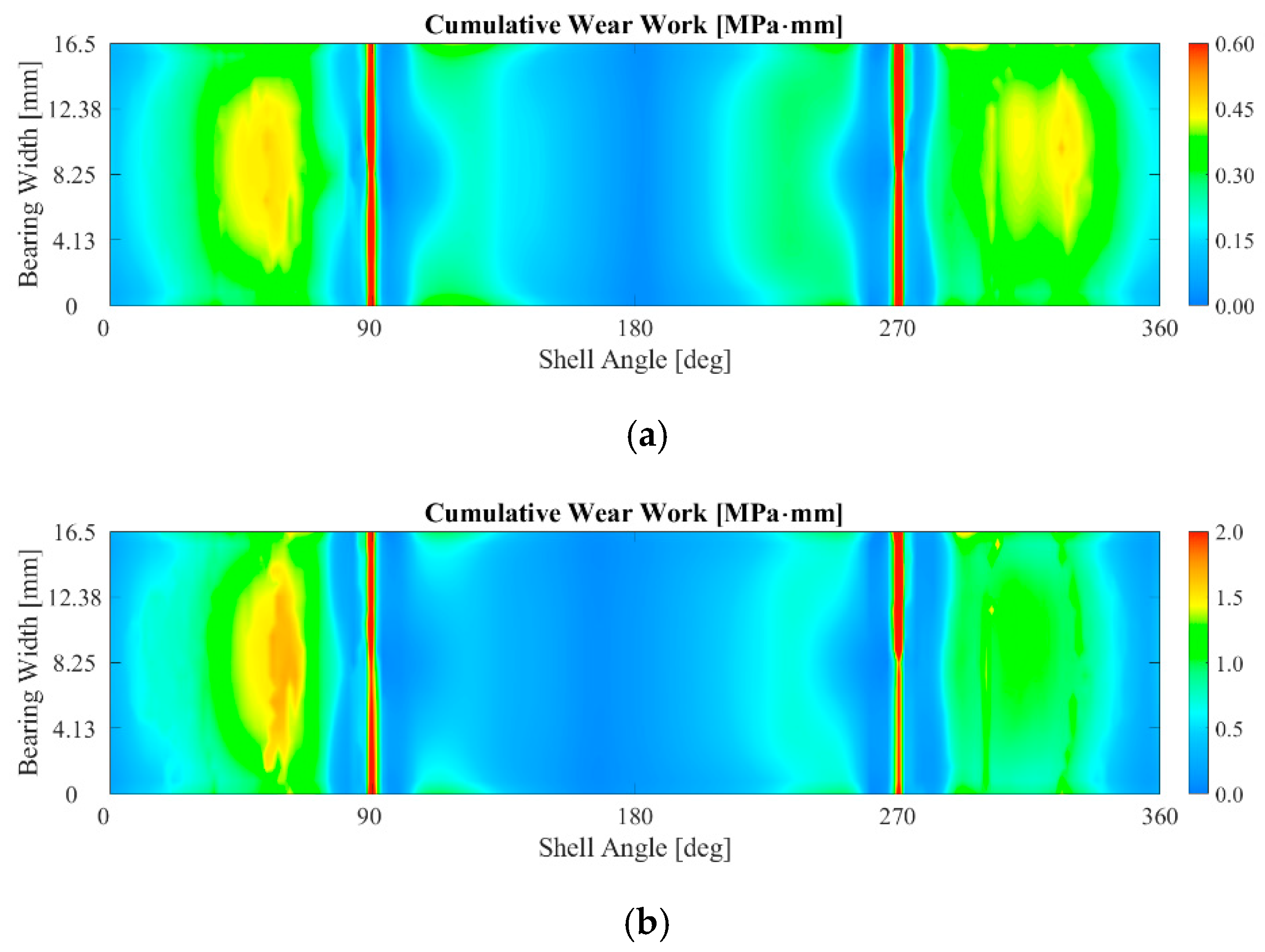
3.1. The Influence of the Bearing Crush Value on the Fretting Behavior

The bearing crush is the first assembly parameter to be evaluated. Three crush values are compared: the baseline case, a 20% reduced crush, and a 20% increased crush. Figure 16b illustrates the variation of the Ruiz parameter on the surface of the connecting rod big end in the baseline case, while Figure 16a,c display the Ruiz parameter values for the reduced crush and increased crush cases, respectively. It is evident that increasing the crush led to a higher intensity of fretting fatigue. Specifically, following a 20% increase in crush height, a corresponding 10% rise in the Ruiz parameter is observed. Conversely, reducing the crush height by 20% led to an approximately 8% decrease in the Ruiz parameter. However, it is useful to discuss the contributions associated with circumferential alternating stress and wear work individually.
Figure 17a–c depict the stress values for the reduced crush, baseline, and increased crush configurations, respectively. Stresses are marginally affected by the specific crush value adopted, at least in the range under investigation.
Figure 18a–c present the cumulative specific wear work values for the reduced crush, baseline, and increased crush configurations, respectively. It can be noted that wear work increases with an increase in crush. This result can easily be justified if one considers that as the bearing crush increases, the press-fitting pressure at the bearing–big end interface also increases. At the same time, higher press-fitting pressures can lead to lower relative displacements, possibly compensating for the effect of the pressure increase in the wear work evaluation; see Equation (2). In this case, however, a marginal influence of the bearing crush on the cumulative relative displacement is observed (see Figure 19), and the effect of increasing press-fitting pressure wins out in driving the increase in cumulative wear work (see Figure 20).

3.2. The Influence of the Bolt Tightening on the Fretting Behavior

Bolt tightening is the second parameter to be investigated. The baseline case is compared with a case in which bolt tightening is increased in such a way that in operating, considering the different thermal expansions of the titanium conrod and of the steel bolts, the bolt tightening corresponds to the nominal one used during the machining phase. The use of this particular procedure ensures that the lemon shape profile of the bearing in hot operating conditions is as close as possible to the nominal one without being affected by a relaxation promoted by the different expansions of the connecting rod and bolts. However, it should be emphasized that, at least for the operating condition, a desired profile of the bearing can always be obtained by suitably defining its cold profile and the adopted bolt tightening. Therefore, in this case, the hydrodynamic pressure obtained by the same elasto-hydrodynamic analysis performed with the bearing profile extracted, considering the nominal bolt tightening (see Figure 4), is used to load the two models.
Figure 21a,b show the value of the Ruiz parameter in these two configurations. It can be seen that barring small differences, the increase in bolt tightening does not cause significant variations in the Ruiz parameter, and only a 1% increase is registered.
This point opens up a possible future discussion on the influence of the bolt tightening and of the specific bearing lemon shape on the hydrodynamic behavior of the bearing rather than on the fretting behavior of the conrod. In fact, having a marginal influence on the fretting parameters, the bolt tightening can be used as a tuning parameter of the assembly procedure of the conrod in order to identify the best combination between bearing cold profile, bolt tightening during machining, and bolt tightening during assembly, which guarantees the best hydrodynamic behavior of the bearing–pin coupling in both cold and hot operating conditions.

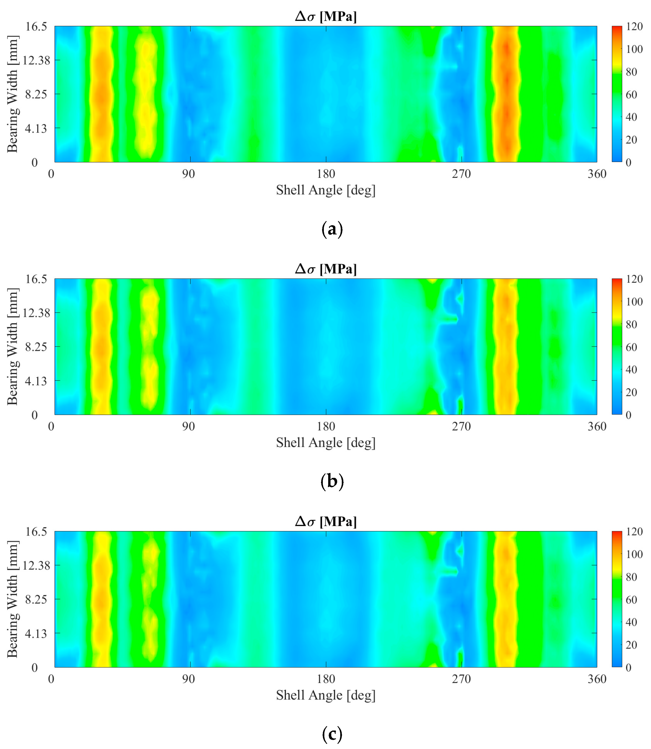
3.3. The Influence of the Friction Coefficient on the Fretting Behavior

The friction coefficient between the connecting rod big end and the bearing is the final parameter to be investigated. For the baseline case, a coefficient of 0.1 is initially set, and then values of 0.2, 0.3, 0.4, and 0.6 are tested. Figure 22 clearly demonstrates that as the friction coefficient increases, the Ruiz parameter also increases, indicating a potentially higher level of fretting fatigue.
Examining Figure 23 and Figure 24, it is evident that the effect of friction directly impacts the wear work, while there are no significant variations in the stress distribution.
The monotonous increase in wear work with increasing friction coefficient is not a foregone conclusion in contact problems. In fact, on the one hand, the increase in friction linearly enters the formula for the definition of wear work (see Equation (2)), but on the other hand, higher friction can lead to lower relative displacements, thus partially compensating the effect of increased friction. In fact, if two opposite asymptotic configurations are examined, the following considerations can be derived: (a) when the friction coefficient is zero, the wear work is obviously zero; (b) when the friction coefficient is high enough to prevent any relative sliding of the elements in contact, the wear work is again zero. For intermediate values of the friction coefficient, the wear work has a value other than zero. It is plausible to hypothesize, therefore, that the wear work follows an increasing and then decreasing trend as a function of the friction coefficient. From this last conclusion, it can be stated that the dependence of the wear work on the friction coefficient is substantially unknown, and it is not possible to establish a universally valid relationship, but it depends on the range of considered friction coefficients, the operating conditions, the materials, and the deformability of the specific analyzed system configuration.
For the specific application addressed in this paper, looking at the trends of the cumulative wear work at points A and B as a function of the friction coefficient in Figure 25, a practically linear relationship can be observed. From an operational point of view, this represents a very useful result since it allows us to perform the calculations for only one value of the friction coefficient, say μ = 0.3, and then scale them according to the desired friction value, at least in the range of investigation, μ = 0.1–0.6.
Furthermore, on the basis of this result, a further improvement in the reliability of the numerical predictions can be included in the procedure described in this work. In fact, a calculation can be initially performed considering a standard uniform initial value of the friction coefficient at the bearing–connecting rod interface, and then results can be processed by locally updating cycle by cycle the value of the friction coefficient as a function of the local value of the accumulated wear work, considering that the specific wear work distribution actually alters the surface finishing of the parts in contact in an uneven way. In this way, the Ruitz parameter can incorporate this non-linearity fueled by a possible dependence between the local wear work and the local friction coefficient. However, in order to define this relationship, it is necessary to carry out a dedicated experimental campaign, which can represent a further future development of this work.

4. Conclusions

This study was aimed at investigating the impact of assembly parameters on fretting fatigue in the contact between the big end and the bearing of a dismountable connecting rod in an internal combustion engine. In particular, some conclusions can be summarized as follows:
  • The primary physical variables involved in the fretting fatigue phenomenon were examined, and the minimum number of time points to simulate were selected, ensuring that the result accuracy was maintained while avoiding excessively lengthy simulations. This allowed the proposed procedure to be used as a guideline to identify limited and selected instants important for the analysis of fretting phenomena in generic complex assemblies subjected to generic complex periodic loads.
  • Once the validity of the simplified approach was established, comparisons were made by varying the bearing crush, bolt tightening, and friction coefficient between the big end and the bearing.
  • It was observed that an increased bearing crush leads to an increase in the fretting damage, mainly promoted by the increased press-fitting contact pressure.
  • Adjusting the tightening torque, with the aim of possibly restoring a more cylindrical surface of the conrod big end in operating condition, was found to marginally affect the fretting parameters, thus opening future discussions on the effect of bolt tightening on the elasto-hydrodynamic phenomena.
  • As for the friction coefficient, it was evident that as the friction coefficient increases, fretting damage parameters increase. Interestingly, a linear relationship was observed between cumulative specific wear work and friction coefficient. Based on these findings, a potential avenue for future development emerges. In particular, the calculation methodology presented can be enhanced by incorporating a variable friction coefficient that increases with the number of engine cycles, considering that as the wear process progresses, the contact surfaces become progressively rougher, resulting in a higher local coefficient of friction and in an intensified wear mechanism over time. This addition will further improve the accuracy of the results from a quantitative perspective, although establishing a direct correlation between the friction coefficient, wear work, and the number of engine cycles remains challenging, and dedicated experimental campaigns are necessary.

Author Contributions

Conceptualization, M.G., F.R. and S.G.B.; methodology, M.G., S.G.B. and V.M.; software, F.R.; validation, F.R., S.G.B. and V.M.; formal analysis, F.R. and S.G.B.; data curation, S.G.B.; writing—original draft preparation, S.G.B. and V.M.; writing—review and editing, S.G.B. and V.M.; supervision, M.G. All authors have read and agreed to the published version of the manuscript.

Funding

This research received no external funding.

Data Availability Statement

Data sharing is not applicable.

Conflicts of Interest

The authors declare no conflict of interest.

References

  1. Strozzi, A.; Baldini, A.; Giacopini, M.; Bertocchi, E.; Mantovani, S. A Repertoire of Failures in Connecting Rods for Internal Combustion Engines, and Indications on Traditional and Advanced Design Methods. Eng. Fail. Anal. 2016, 60, 20–39. [Google Scholar] [CrossRef]
  2. Croccolo, D.; De Agostinis, M.; Fini, S.; Olmi, G.; Robusto, F.; Scapecchi, C. Fretting Fatigue in Mechanical Joints: A Literature Review. Lubricants 2022, 10, 53. [Google Scholar] [CrossRef]
  3. Bill, R.C. Fretting Wear and Fretting Fatigue—How Are They Related? J. Lubr. Technol. 1983, 105, 230–238. [Google Scholar] [CrossRef]
  4. Hills, D.A. Mechanics of Fretting Fatigue. Wear 1994, 175, 107–113. [Google Scholar] [CrossRef]
  5. Sunde, S.L.; Berto, F.; Haugen, B. Predicting Fretting Fatigue in Engineering Design. Int. J. Fatigue 2018, 117, 314–326. [Google Scholar] [CrossRef]
  6. Croccolo, D.; De Agostinis, M.; Fini, S.; Morri, A.; Olmi, G. Analysis of the Influence of Fretting on the Fatigue Life of Interference Fitted Joints. In Proceedings of the Volume 2B: Advanced Manufacturing; American Society of Mechanical Engineers, Montreal, QC, Canada, 14–20 November 2014; pp. 1–10. [Google Scholar]
  7. Croccolo, D.; De Agostinis, M.; Fini, S.; Olmi, G.; Paiardini, L.; Robusto, F.; Scapecchi, C. Fretting Fatigue of Interference Fitted Joints: Development of a Novel Specimen for Four-Point Rotating-Bending Tests and Experimental Results. Eng. Fail. Anal. 2023, 144, 106994. [Google Scholar] [CrossRef]
  8. Berto, F.; Croccolo, D.; Cuppini, R. Fatigue Strength of a Fork-Pin Equivalent Coupling in Terms of the Local Strain Energy Density. Mater. Des. 2008, 29, 1780–1792. [Google Scholar] [CrossRef]
  9. Barbieri, S.G.; Mangeruga, V.; Giacopini, M.; Callegari, M.S.; Bagnoli, L. Effect of the Thermal Mean Stress Value on the Vibration Fatigue Assessment of the Exhaust System of a Motorcycle Engine. SAE Int. J. Engines 2023, 16, 03–16-08–0057. [Google Scholar] [CrossRef]
  10. Mangeruga, V.; Renso, F.; Barbieri, S.G.; Giacopini, M.; Raimondi, F. Numerical Investigation of the Dynamic Effects on the Fatigue Behaviour of a Transmission Chain in a Hybrid Power Unit. J. Multiscale Model. 2023, 14, 1–29. [Google Scholar] [CrossRef]
  11. Kunzelmann, B.; Rycerz, P.; Xu, Y.; Arakere, N.K.; Kadiric, A. Prediction of Rolling Contact Fatigue Crack Propagation in Bearing Steels Using Experimental Crack Growth Data and Linear Elastic Fracture Mechanics. Int. J. Fatigue 2023, 168, 107449. [Google Scholar] [CrossRef]
  12. Morales-Espejel, G.E.; Rycerz, P.; Kadiric, A. Prediction of Micropitting Damage in Gear Teeth Contacts Considering the Concurrent Effects of Surface Fatigue and Mild Wear. Wear 2018, 398–399, 99–115. [Google Scholar] [CrossRef]
  13. Feyzi, M.; Fallahnezhad, K.; Taylor, M.; Hashemi, R. A Review on the Finite Element Simulation of Fretting Wear and Corrosion in the Taper Junction of Hip Replacement Implants. Comput. Biol. Med. 2021, 130, 104196. [Google Scholar] [CrossRef] [PubMed]
  14. McColl, I.R.; Ding, J.; Leen, S.B. Finite Element Simulation and Experimental Validation of Fretting Wear. Wear 2004, 256, 1114–1127. [Google Scholar] [CrossRef]
  15. Ding, J.; McColl, I.R.; Leen, S.B.; Shipway, P.H. A Finite Element Based Approach to Simulating the Effects of Debris on Fretting Wear. Wear 2007, 263, 481–491. [Google Scholar] [CrossRef]
  16. Muflikhun, M.A.; Adyudya, M.; Rahman, N.F.; Sentanuhady, J.; Raghu, S.N.V. Comprehensive Analysis and Economic Study of Railway Brake Failure from Metal-Based and Composites-Based Materials. Forces Mech. 2023, 12, 100223. [Google Scholar] [CrossRef]
  17. Ruiz, C.; Boddington, P.H.B.; Chen, K.C. An Investigation of Fatigue and Fretting in a Dovetail Joint. Exp. Mech. 1984, 24, 208–217. [Google Scholar] [CrossRef]
  18. Barbieri, S.G.; Mangeruga, V.; Giacopini, M. The Effects of the Specific Material Selection on the Structural Behaviour of the Piston-Liner Coupling of a High Performance Engine. In Proceedings of the SAE Technical Papers, Digital summit, 21 September 2021; pp. 1–15. [Google Scholar]
  19. Strozzi, A.; Mantovani, S.; Barbieri, S.G.; Baldini, A. Two Analytical Structural Models of the Connecting Rod Cap. Proc. Inst. Mech. Eng. C J. Mech. Eng. Sci. 2023, 1, 1–17. [Google Scholar] [CrossRef]
  20. Le Falher, M.; Fouvry, S.; Arnaud, P.; Maurel, V.; Antoni, N.; Billardon, R. Fretting-Fatigue of Shrink Fit Lug-Bush Assemblies: Interference-Fit Effect. Tribol. Int. 2023, 186, 108581. [Google Scholar] [CrossRef]
  21. Chao, J. Fretting-Fatigue Induced Failure of a Connecting Rod. Eng. Fail. Anal. 2019, 96, 186–201. [Google Scholar] [CrossRef]
  22. Pujatti, M.; Suhadolc, M.; Piculin, D. Fretting-Initiated Fatigue in Large Bore Engines Connecting Rods. Procedia Eng. 2014, 74, 356–359. [Google Scholar] [CrossRef]
  23. Son, J.H.; Ahn, S.C.; Bae, J.G.; Ha, M.Y. Fretting Damage Prediction of Connecting Rod of Marine Diesel Engine. J. Mech. Sci. Technol. 2011, 25, 441–447. [Google Scholar] [CrossRef]
  24. Badding, B.; Bhalerao, M.; Dowell, J.P.; Gambheera, R.; Sundaram, S. A Method to Predict Fretting in Diesel Engine Connecting Rod Bearing Bores. In Proceedings of the ASME 2004 Internal Combustion Engine Division Fall Technical Conference, Long Beach, CA, USA, 24–27 October 2004; ASMEDC: New York, NY, USA, 2004; pp. 607–616. [Google Scholar]
  25. Merritt, D.; Zhu, G. The Prediction of Connecting Rod Fretting and Fretting Initiated Fatigue Fracture. In Proceedings of the SAE Technical Papers, Tampa, FL, USA, 25 October 2004; Volume 113, pp. 1633–1638. [Google Scholar]
  26. Cebon, D.; Ashby, M.F.; Bream, C.; Lee-Shothaman, L. CES EduPack User’s Manual . 2023. Available online: https://www.ansys.com/products/materials/granta-edupack (accessed on 1 July 2023).
  27. MSC Software Corporation Marc 2023.2 User Documentation, Volume A: Theory and User Information. 2023. Available online: https://simcompanion.hexagon.com/customers/s/article/msc-marc-volume-a--theory-and-user-information-doc9245 (accessed on 1 July 2023).
  28. Zienkiewicz, O.C. The Finite Element Method: Its Basis and Fundamentals. In The Finite Element Method: Its Basis and Fundamentals; Elsevier: Amsterdam, The Netherlands, 2013; p. iii. [Google Scholar]
  29. Press, W.H.; Teukolsky, S.A.; Vetterling, W.T.; Flannery, B.P. Numerical Recipes: The Art of Scientific Computing, 3rd ed.; Cambridge University Press: Cambridge, UK, 2007; Volume 1, ISBN 978-0-521-88068-8. [Google Scholar]
  30. Depouhon, P.; Sprauel, J.M.; Mermoz, E. Prediction of Residual Stresses and Distortions Induced by Nitriding of Complex 3D Industrial Parts. CIRP Ann. 2015, 64, 553–556. [Google Scholar] [CrossRef]
  31. Londhe, A.; Yadav, V.; Sen, A. Finite Element Analysis of Connecting Rod and Correlation with Test. In Proceedings of the SAE Technical Papers, Detroit, MI, USA, 20 April 2009. [Google Scholar]
  32. Robert, B.; Brown, E.B. Engine Oils and Automotive Lubrication; Bartz, W.J., Ed.; CRC Press: Boca Raton, FL, USA, 2019; ISBN 9780203757451. [Google Scholar]
  33. Pirro, D.; Webster, M.; Daschner, E. Lubrication Fundamentals, Third Edition, Revised and Expanded; CRC Press: Boca Raton, FL, USA, 2016; ISBN 978-1-4987-5290-9. [Google Scholar]
  34. Neale, M.J. Tribology Handbook; Elsevier: Amsterdam, The Netherlands, 1995; ISBN 9780750611985. [Google Scholar]
Figure 1. The discretized components involved in the analyses: (a) complete assembly and section view; (b) reference system.
Lubricants 11 00375 g001
Figure 2. The definition of the crush for a generic big end bearing.
Lubricants 11 00375 g002
Figure 3. Detail of the contact bodies and the mesh adopted for the FE simulations.
Lubricants 11 00375 g003
Figure 4. The elasto-hydrodynamic pressure distribution: (a) 0° CA; (b) 180° CA; (c) 360° CA; (d) 540° CA.
Lubricants 11 00375 g004aLubricants 11 00375 g004b
Figure 5. Pressure distribution at the crank pin–big end bearing interface close to top dead center during combustion (4° CA): (a) direct contact pressure distribution of a FEM model; (b) elasto-hydrodynamic pressure distribution.
Lubricants 11 00375 g005
Figure 6. Reference system adopted for the boundary conditions: (a) load on the connecting rod; (b) accelerations at the small end and at the big end of the connecting rod.
Lubricants 11 00375 g006
Figure 7. Load acting on the connecting rod small end.
Lubricants 11 00375 g007
Figure 8. Acceleration applied on the connecting rod: (a) component aligned with the connecting rod axis; (b) component orthogonal to the connecting rod axis.
Lubricants 11 00375 g008
Figure 9. Cumulative specific wear work on the inner surface of the big end for the simulated whole engine cycle.
Lubricants 11 00375 g009
Figure 10. Cumulative wear work as a function of crank angle for the two selected points A and B on the inner surface of the big end for the simulated whole engine cycle.
Lubricants 11 00375 g010
Figure 11. Main parameters for wear work evaluation as a function of crank angle for the two selected points A and B for the simulated whole engine cycle: (a) cumulative relative displacement; (b) contact pressure.
Lubricants 11 00375 g011
Figure 12. Axial force acting on the connecting rod big end.
Lubricants 11 00375 g012
Figure 13. Comparison of the cumulative displacements between the complete and simplified cases: (a) point A; (b) point B.
Lubricants 11 00375 g013
Figure 14. Comparison of the cumulative wear work between the complete and simplified cases: (a) point A; (b) point B.
Lubricants 11 00375 g014
Figure 15. Cumulative specific wear work on the inner surface of the big end for the simplified case.
Lubricants 11 00375 g015
Figure 16. Ruiz parameter: (a) 20% reduced crush; (b) baseline crush; (c) 20% increased crush.
Lubricants 11 00375 g016
Figure 17. Circumferential stress amplitude: (a) 20% reduced crush; (b) baseline crush; (c) 20% increased crush.
Lubricants 11 00375 g017aLubricants 11 00375 g017b
Figure 18. Cumulative wear work: (a) 20% reduced crush; (b) baseline crush; (c) 20% increased crush.
Lubricants 11 00375 g018aLubricants 11 00375 g018b
Figure 19. Comparison of the cumulative relative displacements for the different crush values: (a) point A; (b) point B.
Lubricants 11 00375 g019
Figure 20. Comparison of the cumulative wear works for the different crush values: (a) point A; (b) point B.
Lubricants 11 00375 g020
Figure 21. Ruiz parameter: (a) baseline bolt tightening; (b) 30% increased bolt tightening.
Lubricants 11 00375 g021
Figure 22. Ruiz parameter: (a) 0.1 friction coefficient; (b) 0.4 friction coefficient; (c) 0.6 friction coefficient.
Lubricants 11 00375 g022aLubricants 11 00375 g022b
Figure 23. Cumulative wear work: (a) 0.1 friction coefficient; (b) 0.4 friction coefficient; (c) 0.6 friction coefficient.
Lubricants 11 00375 g023aLubricants 11 00375 g023b
Figure 24. Circumferential stress amplitude: (a) 0.1 friction coefficient; (b) 0.4 friction coefficient; (c) 0.6 friction coefficient.
Lubricants 11 00375 g024
Figure 25. Cumulative wear work as a function of the friction coefficient for the two selected points A and B on the inner surface of the big end.
Lubricants 11 00375 g025
Table 1. Mechanical and physical properties of the materials involved in the analysis.
Component/MaterialMechanical/Physical PropertyValue
Connecting rod/titaniumDensity4.51 g/cm3
Young’s modulus110 GPa
Poisson’s ratio0.3
Thermal expansion9·10−6
Bolts/steelDensity7.8 g/cm3
Young’s modulus207 GPa
Poisson’s ratio0.3
Thermal expansion1.1·10−5
Bearing/steelDensity7.8 g/cm3
Young’s modulus210 GPa
Poisson’s ratio0.3
Thermal expansion1.1·10−5
Table 2. Parameters employed for the contact modeling.
Contact BodiesContact InteractionFriction Coefficient
Conrod shank–conrod capNonlinear unilateral contact0.3
Conrod shank–dowel pinGlued contact0.3
Conrod shank–bearingNonlinear unilateral contact0.1–0.6
Conrod shank–bolts (thread)Nonlinear unilateral contact0.3
Conrod cap–bolts (head)Nonlinear unilateral contact0.3
Conrod cap–bearingNonlinear unilateral contact0.1–0.6
Conrod cap–dowel pinNonlinear unilateral contact0.3
Shank half-bearing–cap half-bearingNonlinear unilateral contact0.3
Table 3. Parameters employed for the simulation of the whole engine cycle.
ParameterValue
Revving speed12,500 rpm
Friction coefficient0.1
Bearing crush0.1 mm
Tightening preload40,000 N
Disclaimer/Publisher’s Note: The statements, opinions and data contained in all publications are solely those of the individual author(s) and contributor(s) and not of MDPI and/or the editor(s). MDPI and/or the editor(s) disclaim responsibility for any injury to people or property resulting from any ideas, methods, instructions or products referred to in the content.

