1. Introduction
The cam-follower unit is an important link in the motion chain of the gas distribution system of internal combustion engines. Its performance affects the accuracy of the intake/exhaust processes in the combustion chamber and thus the running stability and working efficiency of the engine. In the early days, most valve systems used the cam-flat tappet, which has a relatively simple and light structure. However, the contact pairs operate in pure sliding conditions. Many studies were conducted to optimize its frictional performance [
1,
2,
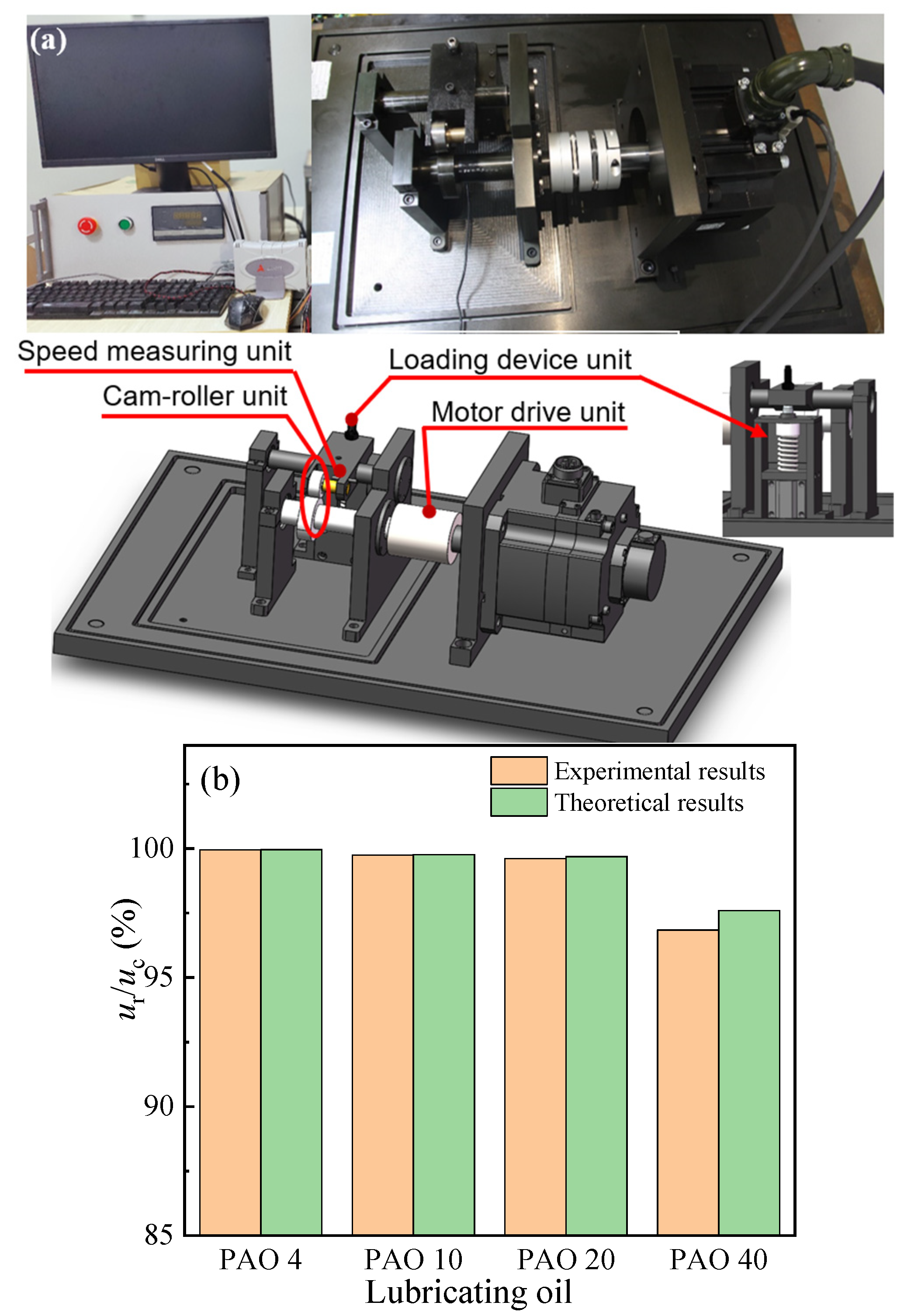
3], but they could not fundamentally change the fact that the motion is purely subject to relative sliding friction. Therefore, modern gas distribution systems tend to use cam-roller followers, as shown in
Figure 1a. Theoretically, the cam and roller are in pure rolling motion throughout the whole working cycle. It has been shown in [
4] that the cam-roller follower can reduce the friction force by 51% under the same working conditions as the cam-flat follower. It can also effectively decrease the wear of the contact surface [
5] and thus increase the fatigue life of the related component [
6]. Therefore, the cam-roller follower can achieve a better frictional lubrication state, which reduces power loss and improves the reliability of the valve mechanism [
7,
8,
9].
In theory, the ideal frictional characteristic of the cam-roller pair requires a pure rolling motion between the cam and the roller. However, in reality, there is some degree of skidding between the cam and the roller in the valve mechanism. Bair et al. [
10] developed a technique to measure the skidding of roller followers on camshafts using optical scanners and observed the minimum slippage between the cam and the roller under certain working conditions. Lee et al. [
11] deduced that the roller slippage occurred at the flank and the base circle using an optical sensor test setup. Slippage exists and can lead to increased wear and damage to the interacting surfaces [
12,
13]. This inevitably increases the energy consumption of the internal combustion engine [
14]. Therefore, it is important to study how to reduce the skidding problem between the cam and the roller.
The cam-roller follower in a real internal combustion engine is a very complex lubricated contact, and its tribological behavior is affected by many factors. Most of the existing experimental studies on the roller follower were conducted extensively on modified test setups that may not reflect the situation of real engine operation [
10,
12]. Some factors, such as the engine operating conditions, lubricant rheology, and lubricant chemistry, were studied under realistic conditions to understand their impact on the roller slippage [
15,
16,
17,
18]. However, the experiments could only obtain an average slide-roll ratio (SRR) over time and could not measure the real-time SRR for different cam rotation angles within a cycle. This limitation of experimental techniques can be solved using theoretical modeling analysis. Chiu [
8] was the first to develop a theoretical lubrication model that considers the variable roller speed at the cam-roller contact, that is, the slippage between the cam and the roller. Turturro et al. [
19] proposed a steady-state model for a non-Newtonian lubricant. They found that the slipping velocity is low in the transition through the cam nose-roller contact. Umar et al. [
2] analyzed the effect of the flash temperature on the cam follower friction. They concluded that the resultant contact temperature is much higher in the case of sliding followers due to higher slippage velocity and friction. In addition, the skidding between the cam and the roller is not only related to the frictional state of its own contact pair but also directly to the connected roller-pin contact pair. Alakhramsing et al. [
20] proposed a joint model that consists of an isothermal-EHL model of the cam-roller contact and a semi-analytical lubrication model of the roller-pin bearing. They found that the impact of the roller slippage on power loss could not be negligible. They then analyzed the conditions of heavy loads [
21] and mixed lubrication [
22]. It can be concluded that skidding depends on the operating conditions. But so far, research on the actual working conditions of internal combustion engines has not been carried out, especially on the exhaust cam pair. This means more severe conditions for numerical analysis, making it very difficult for analytical models to obtain convergent lubrication results. It is true that its operating parameters (such as load, surface velocity, curvature radius, etc.) change greatly throughout the entire working cycle in real-world conditions. Further, the internal combustion engine has a steady and startup process, and whether it has the same skidding situation in both cases also remains to be studied.
Therefore, this paper develops a coupled cam-roller unit lubrication analysis model to analyze skidding and its influence on lubrication performance. This model is based on the actual operating parameters of a specific type of internal combustion engine. The real-time skidding between cam and roller is obtained by an efficient numerical analysis method. In the steady and startup operations of the internal combustion engine, the skidding behavior and the lubrication performance of the cam-roller unit are analyzed around different working parameters (lubricating oil viscosity, applied load). The obtained numerical results can help optimize the friction design of the cam-roller unit of the internal combustion engine.
2. Theoretical Model and Solver
Figure 1a shows a photograph of the cam-roller unit in a certain type of internal combustion engine. In theory, the cam and the roller are in a pure rolling state. However, due to the friction between the roller and the pin, the roller is subjected to a resistance moment when it moves. As a result, the surface speeds of the cam and the roller cannot be synchronized in real-time, which causes skidding between them. Based on this, a corresponding lubrication analysis model is developed (
Figure 1b). The model includes two parts: cam-roller contact (Elastohydrodynamic lubrication model) and roller-pin contact (Hydrodynamic lubrication model). The shared part (the roller) becomes the key to establishing the internal correlation between the cam-roller contact and the roller-pin contact. This requires two kinematic pairs to ensure that all forces acting on the roller achieve a balanced state:
where
fcrRr1w and
frpRr2w are, respectively, the torque of the cam and the pin on the roller, and
Irώr is the inertia torque of the roller.
2.1. Cam-Roller Contact Pair
The finite-length elastohydrodynamic lubrication model is developed based on the cam-roller contact pair while considering the thermal effect.
The modified generalized dynamic Reynolds equation is used [
23]:
where
The boundary condition of the Reynolds equation is given by:
The film thickness equation is given by [
24]:
where
fΔ is a sign function,
fΔ = 1 if
, and
fΔ = 0 if
.
The viscosity–pressure–temperature relation proposed by Roelands [
25] is used. It can be expressed as:
where
A1 = ln
η0 + 9.67,
A2 = 5.1 × 10
−9 Pa
−1,
A3 = 1/(
T0 − 138),
A4 = 138/(
T0 − 138),
Z0 =
α/(
A1A2), and
S0 =
β0/(
A1A3).
The density–pressure–temperature relation [
26] is given by:
where
C1 = 0.6 × 10
−9 Pa
−1,
C2 = 1.7 × 10
−9 Pa
−1, and
C3 = 0.00065 K
−1.
The load balance equation is given by:
where
w and
w1 are the measured and modified load values, respectively.
The energy equation of the lubricating oil film can be obtained without considering the influence of the volume force and thermal radiation, while ignoring the heat conduction along the
x and
y directions [
27]:
where
.
The energy equations for the cam and the roller are given by:
The conditions of Equations (7) and (8) are given by:
The friction coefficient is calculated as [
24]:
2.2. Roller-Pin Contact Pair
Based on the roller-pin contact pair, the finite-length fluid lubrication model is developed based on the roller-pin contact pair while considering the thermal effect. The average flow Reynolds equation is given by [
28]:
The boundary conditions of the Reynolds equation are given by:
The film thickness equation can be written as [
29]:
The energy equations are given by [
30]:
The conditions of the energy equations are expressed as:
The friction coefficient is computed as [
30]:
2.3. Numerical Calculation Process
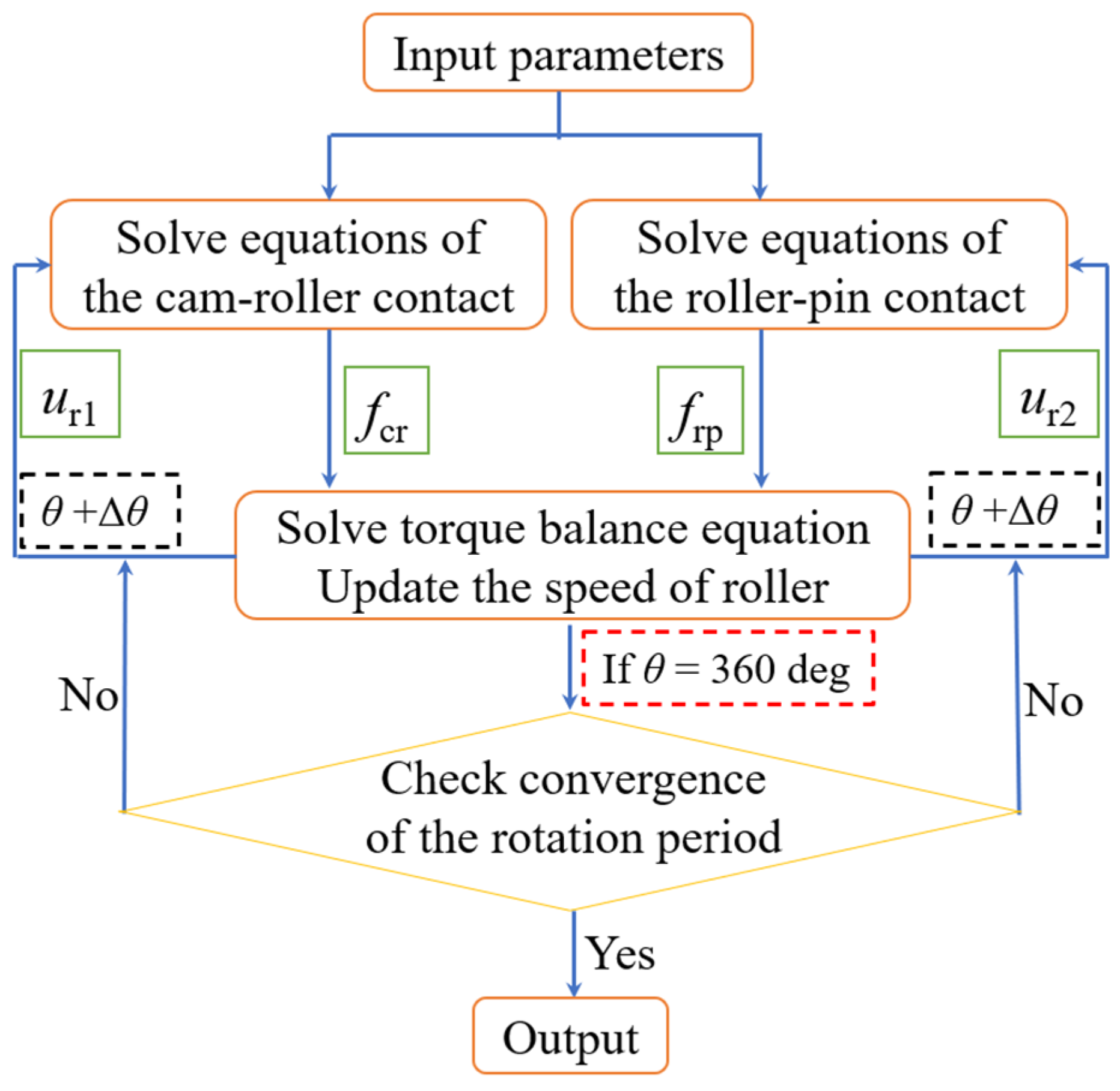
The cam-roller unit consists of two independent and associated motion pairs, as shown in
Figure 1. The key control equations and the coupling connection equation are also provided. The solution of the lubrication model is based on the non-dimensionalization of Equations (1)–(13). The specific process is shown in
Figure 2. The solving process of the two lubrication models is similar to that presented in [
24,
29], and thus it is not presented in this study. It is important to mention that the friction force can be obtained by lubrication analysis of two motion pairs under a certain cam rotation. Using the torque balance equation (Equation (1)), the roller’s angular acceleration can be determined, and the rotation speed of the roller at the next angle (i.e., the updated roller speed) can be obtained. The lubrication analysis goes to the next rotation angle, and the process is repeated again. Finally, the lubrication state of the cam-roller unit at each rotation angle in a complete cycle is obtained.
4. Results and Discussion
This paper aims at numerically studying the lubrication of the cam-roller unit in a complete cam rotation cycle and analyzing the influencing factors of the skidding between the cam and the roller during the steady/startup operation of the internal combustion engine. The working parameters shown in
Table 1 are provided by the industry partner.
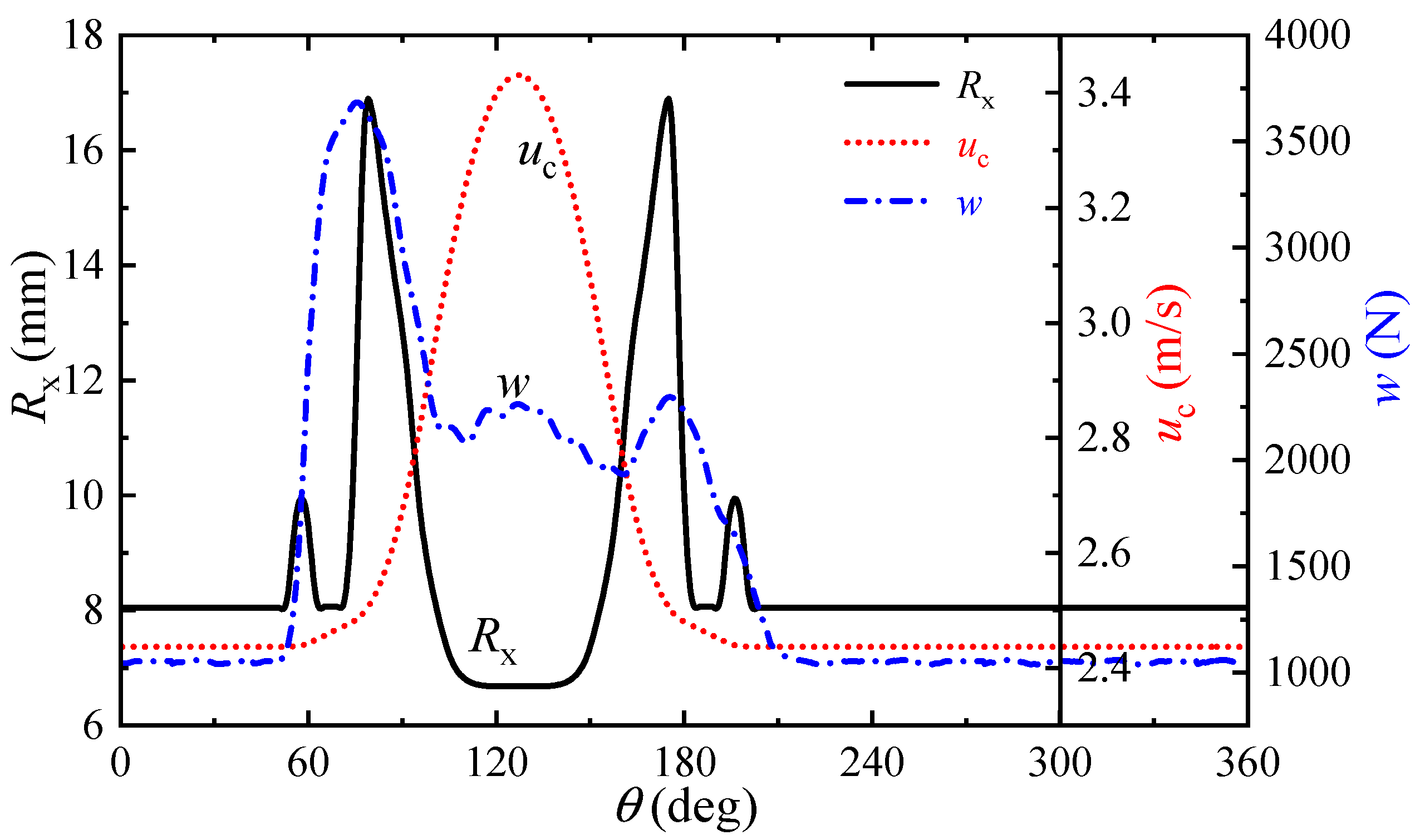
The main characteristic of the cam-follower pair in the internal combustion engine is the change in comprehensive curvature, velocity, and load with cam rotation, as shown in
Figure 4, which presents a set of its specific working parameters. The cam nose appears at 127°, and the rotation angle of 54–200° is located in the non-base circle of the cam. The load spectrum of the exhaust cam-roller pair is measured from the test bench of an internal combustion engine under real working conditions. At the starting stage of the cam lift, that is, the initial phase of exhaust travel in the valve mechanism, the contact load sharply increases. This is an important characteristic of the exhaust cam-roller pair. The change in the curvature of the cam in the non-base circle results in a change in the comprehensive curvature radius of the cam-roller contact. If the cam-roller contact is in a pure rolling motion state, the two velocities of the solid surfaces are equal (
uc =
ur1). Otherwise, there is a relative motion between the cam and the roller, which is described by the slide-roll ratio (
SRR = 2(
uc −
ur1)/(
uc +
ur1)).
4.1. Skidding at Steady Running Process
In the internal combustion engine, the cam and roller are theoretically designed in the pure rolling state. However, in practice, there is a skidding phenomenon between them. Is there consistency in the working conditions of the cam-roller unit under the two operating states (skidding and pure rolling)? Therefore, the lubrication states are obtained in a cam rotation cycle under the conditions of skidding (
uc ≠
ur1) and pure rolling (
uc =
ur1), as shown in
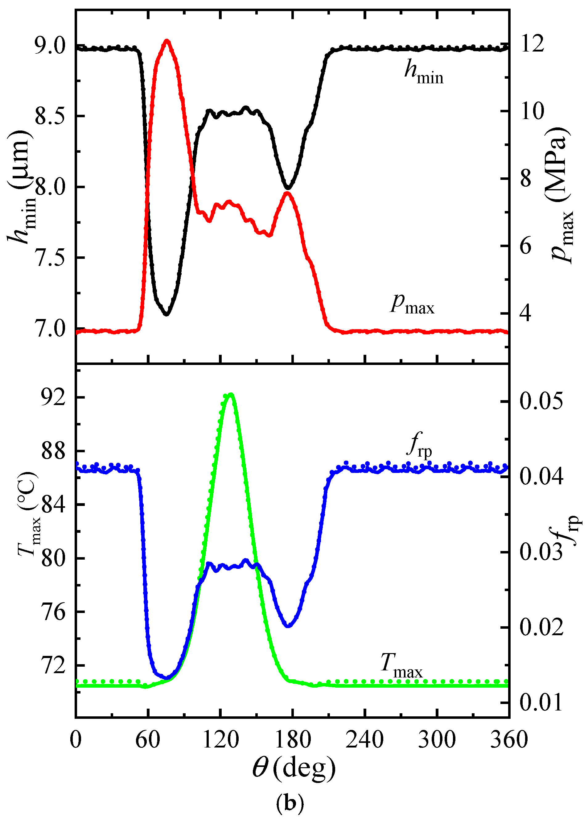
Figure 5, where the lubricant viscosity (
η0) is equal to 0.152 Pa · s and the modified load (
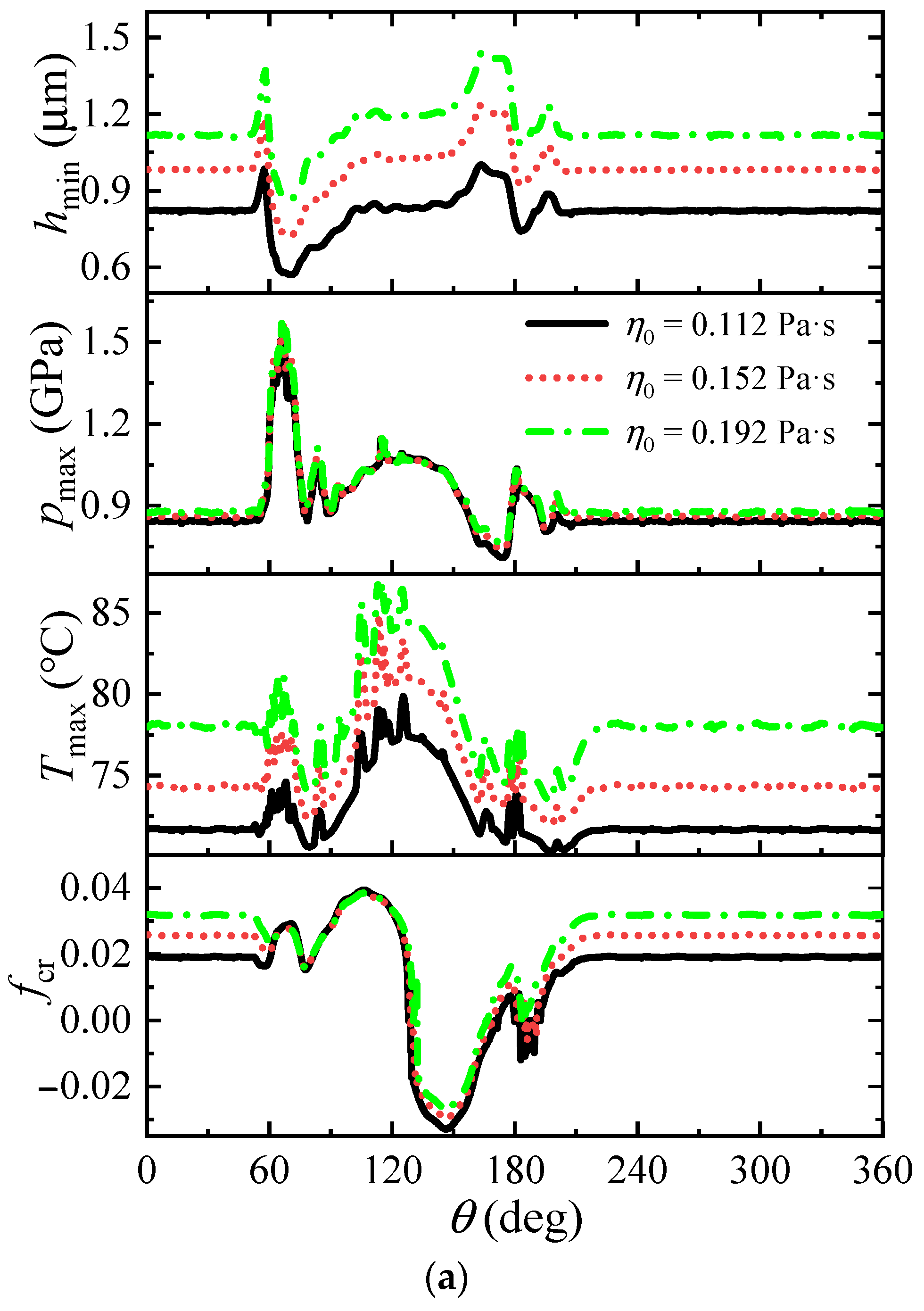
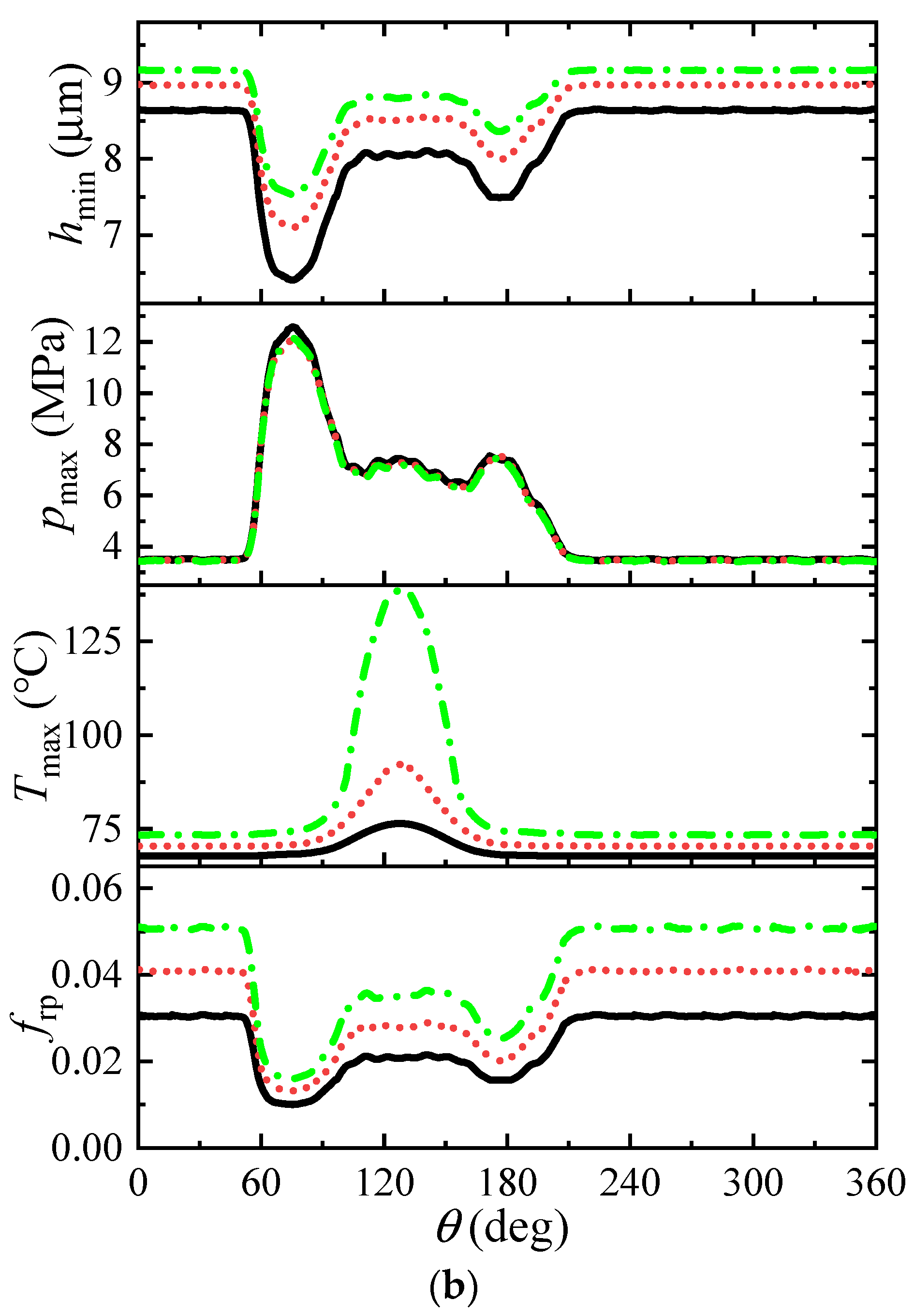
w1) is null. On the one hand, it can be deduced from the overall perspective trend of the minimum film thickness, maximum pressure, maximum temperature increase, and friction coefficient that the lubrication state of the cam-roller unit is stable at the rotation angle of the cam base circle part, while the lubrication parameters change significantly at the other rotation angles. This corresponds to the changes in the operating condition parameters such as cam curvature, cam surface velocity, and applied load in
Figure 4. The lubrication analysis results can reflect the lubrication state of the cam-roller unit under different working conditions in real-time. On the other hand, the existence of skidding between the cam and the roller has almost no effect on the lubrication state of the roller-pin pair. In fact, even after skidding occurs, it will not greatly change the roller speed, which can be verified by the slide-roll ratio shown in
Figure 6. For the same reason, the influence of skidding on the minimum film thickness and the maximum pressure is also very small in the cam-roller pair, while the maximum temperature rise and the friction coefficient will be greatly affected. Even a small skid on the surfaces between the cam and the roller can make the friction coefficient no longer equal to zero, which changes the temperature of the contact zone. Therefore, the skidding phenomenon between the cam and the roller mainly affects the temperature rise and the friction coefficient of the lubrication state in the cam-roller unit.
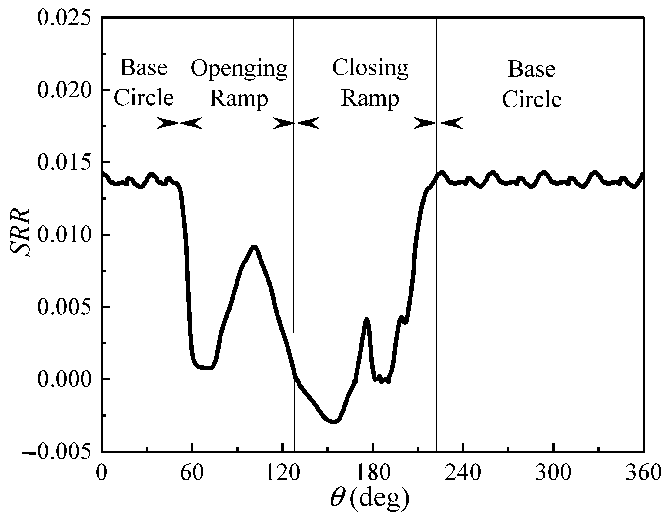
According to the above skidding condition, the slide-roll ratio variation between the cam and the roller in a complete cam rotation cycle is obtained, as shown in
Figure 6. It can be seen that the slide-roll ratio remains relatively constant and increases with the rotation angle of the cam base circle. This is because the working condition parameters are almost unchanged in the rotation angle of the cam base circle (
Figure 4). Moreover, according to the torque equilibrium formula (Equation (1)), it is necessary to apply enough driving torque to drive the roller to rotate. However, the contact load of this part is relatively low, and thus the friction coefficient should reach a certain relatively large value to realize the driving of the roller, which requires a relatively large surface speed difference between the cam and the roller. In the opening and closing ramps of the cam (54–200°), the value of the slide-roll ratio changes significantly. At the beginning of the cam opening ramp, the contact load increases sharply and the lubricating oil film decreases. Large surface speed differences are no longer required to achieve the required driving torque for the roller, and thus the slide-roll ratio decreases rapidly. When the cam lift increases, the surface velocity of the cam also starts to increase. This requires the roller to accelerate to follow, and the driving force required by the roller will inevitably increase. The slide-roll ratio starts to show an upward trend to obtain a relatively large friction coefficient. Although the contact load at this stage is relatively lower than at the initial stage of the cam opening ramp, it is still relatively large. Therefore, the rising amplitude value of the slide-roll ratio (
θ ≈ 100°) does not exceed its value in the rotation angle of the cam base circle. Afterwards, the increasing trend of the cam surface velocity gradually slows down, and the driving torque required by the roller also decreases. The slide-roll ratio also shows a downward trend, and even its value is almost zero at the cam tip position. The cam starts to enter the closing ramp stage, and its surface velocity decreases accordingly. At this time, the roller still has a high speed. The latter only depends on the impedance torque between the roller and the pin to produce the deceleration effect, which is less than the deceleration degree of the cam surface velocity. Consequently, the surface velocity of the cam is less than that of the roller. However, once there is a surface velocity difference between the cam and the roller, the contact pair will generate an impedance torque of the roller movement, which functions with the impedance torque of the roller-pin pair to reduce the rotational speed of the roller. The slide-roll ratio has a small negative value (|
SRR| < 0.003). As each parameter gradually returns to the working condition of the cam base circle, the slide-roll ratio also returns to a relatively stable value. It can be seen that the intrinsic requirement of the cam-roller unit causes the change in the slide-roll ratio, which is related to the coupled lubrication state of the cam-roller contact and roller-pin contact at each cam rotation angle.
4.1.1. Effect of Oil Viscosity
According to previous classical lubrication analyses, the viscosity of the lubricating oil is an important parameter affecting the lubrication state of the contact zone. However, its effect on skidding in the cam-roller unit has not been studied yet.
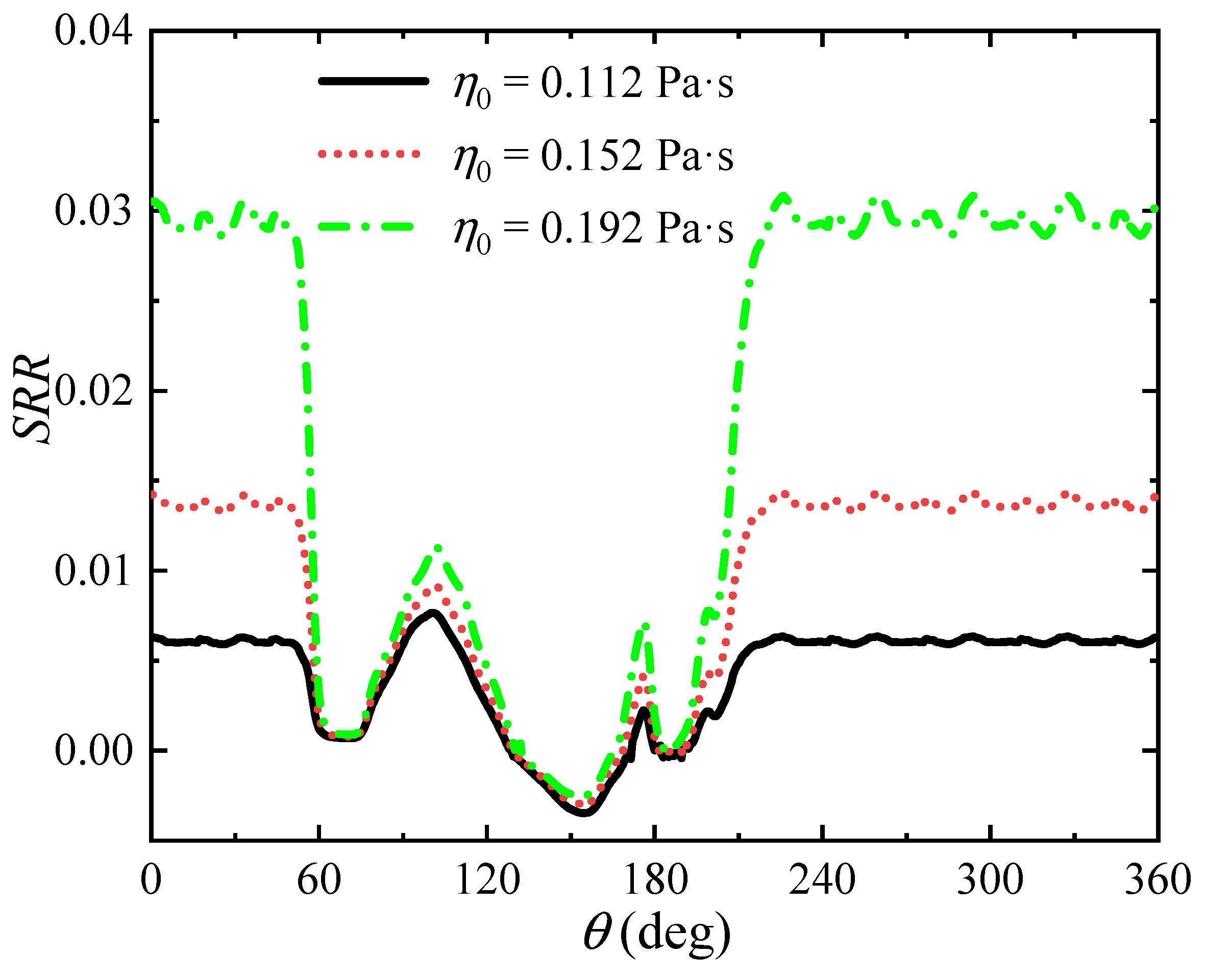
Figure 7 shows the curves of the slide-roll ratio in a complete cam rotation cycle with three oil viscosities, where
w1 = 0 N. It can be clearly seen that the skidding condition is affected by the oil viscosity, and this effect is only reflected in the numerical value of the slide-roll ratio and not its regularity in a cam rotation cycle. The change in the slide-roll ratio is larger in the rotation angle of the cam base circle part. The oil viscosity can change the friction coefficient of the roller-pin contact (
Figure 8), which in turn changes the driving torque required for the roller motion. However, at the rotation angle of the cam base circle, the contact load is relatively small, and the friction coefficient of the cam-roller contact should significantly change, resulting in an obvious change in the slide-roll ratio. The contact load is relatively large in the rotation angle of the cam opening and closing ramp, and thus the change in the slide-roll ratio is small. In addition, the oil viscosity also affects the minimum film thickness and the maximum temperature increase in the cam-roller unit, which is consistent with the classical lubrication theory. Therefore, the oil viscosity can change the skidding between the cam and the roller in the cam-roller unit.
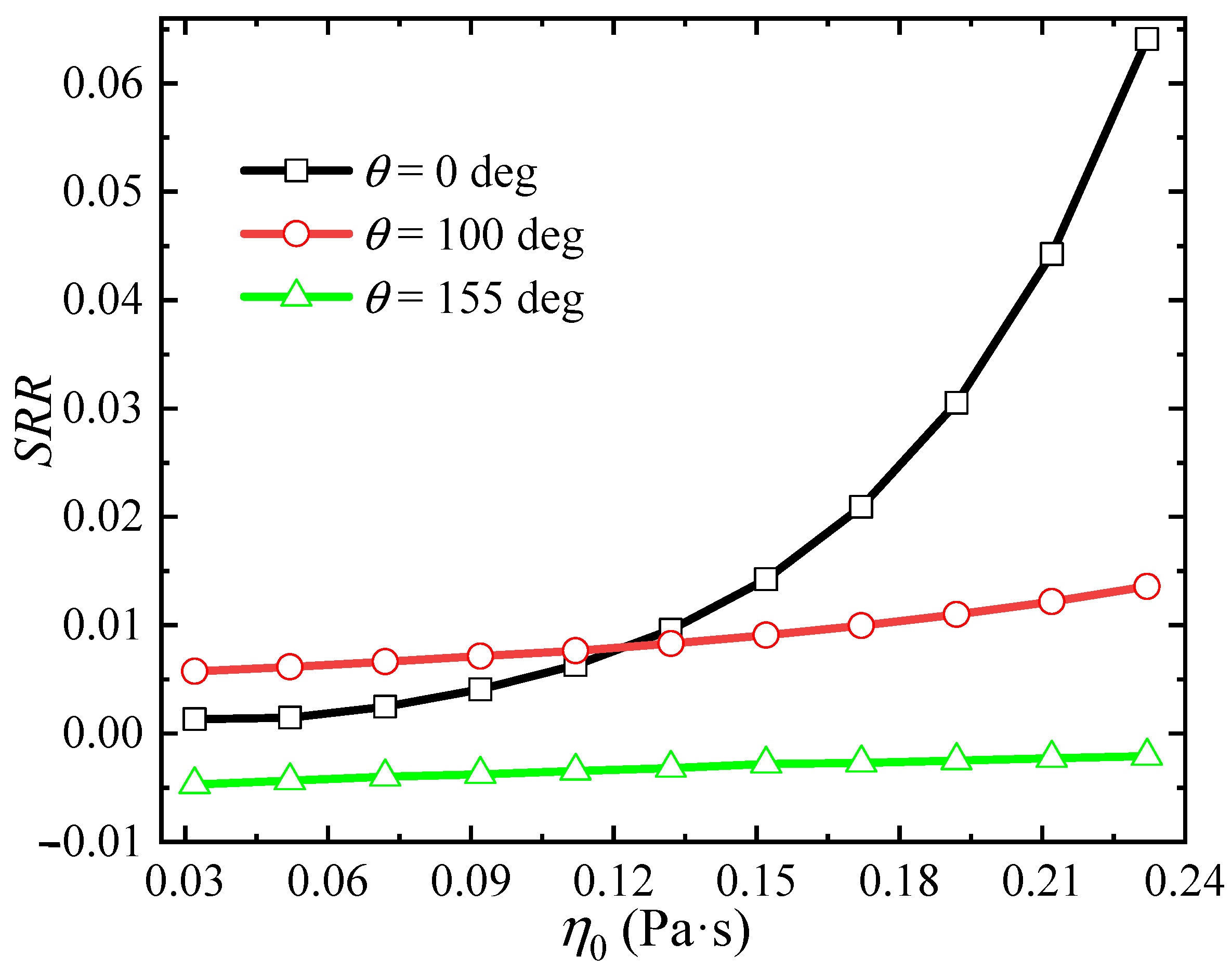
In order to further analyze the influence of oil viscosity on skidding, the slide-roll ratio is plotted as a function of viscosity at three special points (0°—located in the cam base circle part and 100/155°—located at the local maximum positive/negative value of the slide-roll ratio in the non-cam base circle part), as shown in
Figure 9. It can be seen that the slide-roll ratios at the three cam rotation angles are affected by the oil viscosity to different degrees, with the most drastic change at 0° and relatively weak changes at 100° and 155°. As previously mentioned, the sensitivity of the slide-roll ratio to the oil viscosity is always affected by the contact load. For 0° and 100°, the increase in oil viscosity can increase skidding between the cam and the roller. Especially for the rotation angle of the cam base circle part (0°), when the oil viscosity is greater than 0.112 Pa·s, the changing curvature of the slide-roll ratio is greater than 10%. In other words, if the oil viscosity is less than 0.112 Pa·s, the skidding phenomenon will no longer be very sensitive to the change in oil viscosity. It is important to mention that at 155°, the skidding slightly decreases with increasing oil viscosity. This is due to the increase in the impedance torque of the roller-pin pair with increasing oil viscosity (
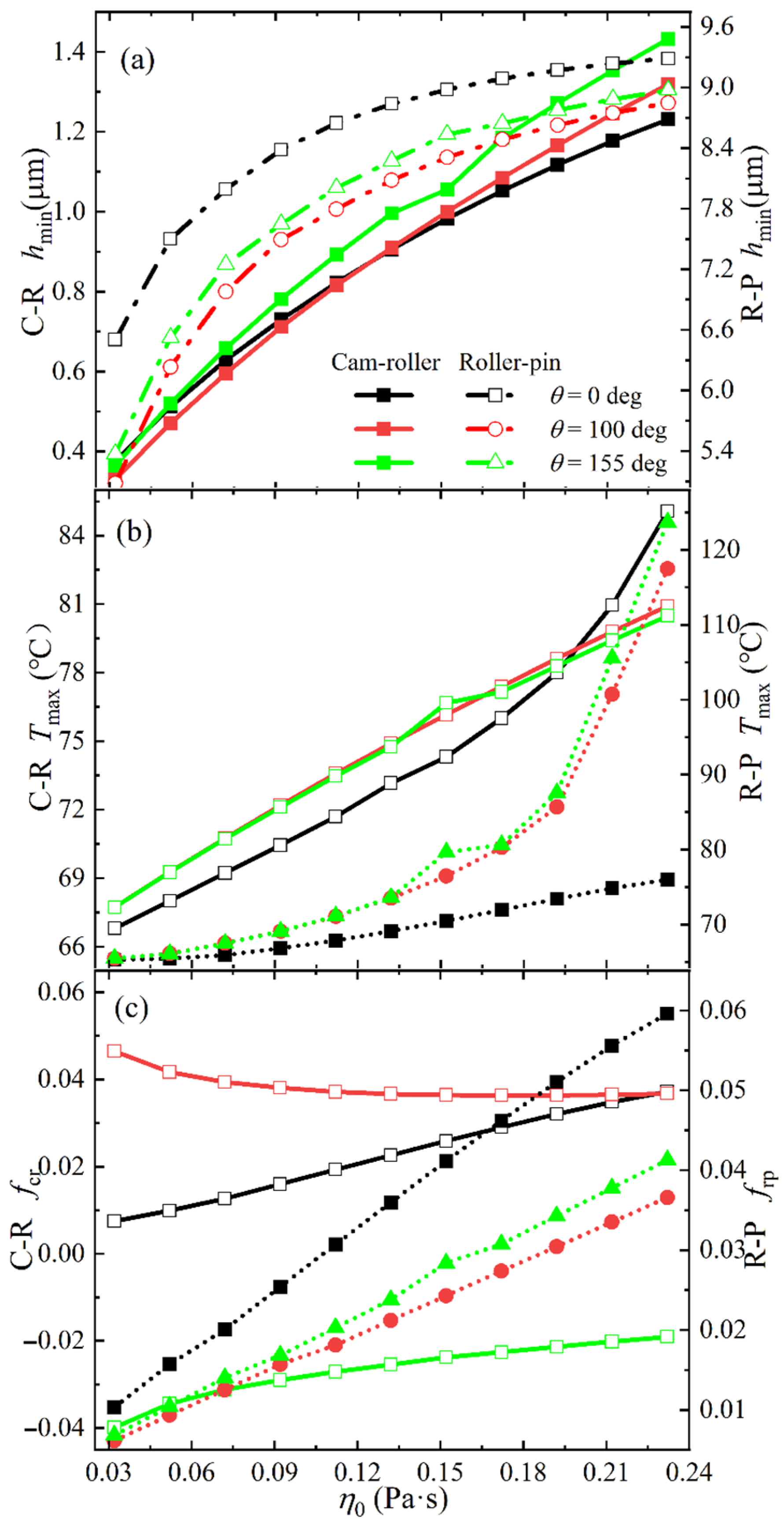
Figure 10), and only the small impedance torque provided by the cam-roller pair can reduce the roller following speed. In addition, the oil viscosity affects the minimum film thickness, maximum temperature increase, and friction coefficient, as shown in
Figure 10. Moreover, the lower the oil viscosity, the better the maximum temperature increase of the cam-roller unit and the friction coefficient of the roller-pin pair. However, low viscosity leads to a smaller minimum film thickness, and the friction coefficients at 100° and 155° increase with decreasing viscosity. These conditions limit small values of oil viscosity to ensure good lubrication in the cam-roller unit. In general, choosing an oil with low viscosity can reduce skidding without affecting the effective lubrication of the cam-roller unit.
4.1.2. Effect of the Modified Load
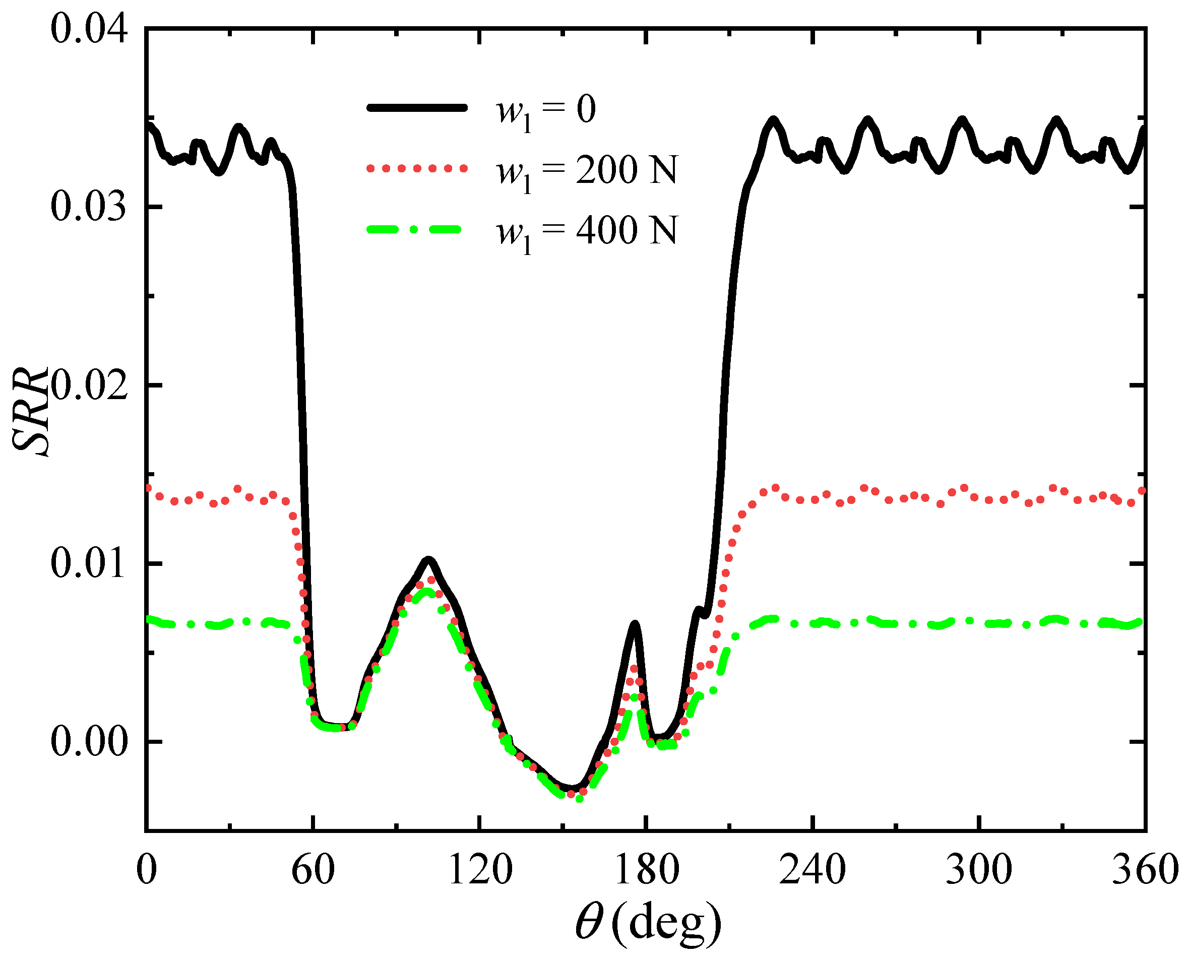
The variation of contact load with cam rotation is an important characteristic of the cam-follower pair. To ensure good contact between the cam and the roller, the contact pair usually requires maintaining a certain static contact load, that is, the initial applied load. The modified load is used to adjust the value of the initial applied load to analyze its influence on skidding in the cam’s complete rotation cycle, as shown in
Figure 11. It can be clearly seen that skidding is affected by the initial applied load, especially in the rotation angle of the cam base cycle. It can also be observed from the load change in
Figure 4 that the proportion of modified load in the total contact load is relatively large at this stage. Therefore, the slide-roll ratio is more easily affected by the modified load. After increasing the initial load, a smaller friction coefficient in the cam-roller contact (
Figure 12) can meet the kinematic requirements of the cam-roller unit. This indicates that the velocity difference between the cam and the roller is small, i.e., a smaller slide-roll ratio. Therefore, increasing the initial load can reduce skidding in this part of the cam base cycle.
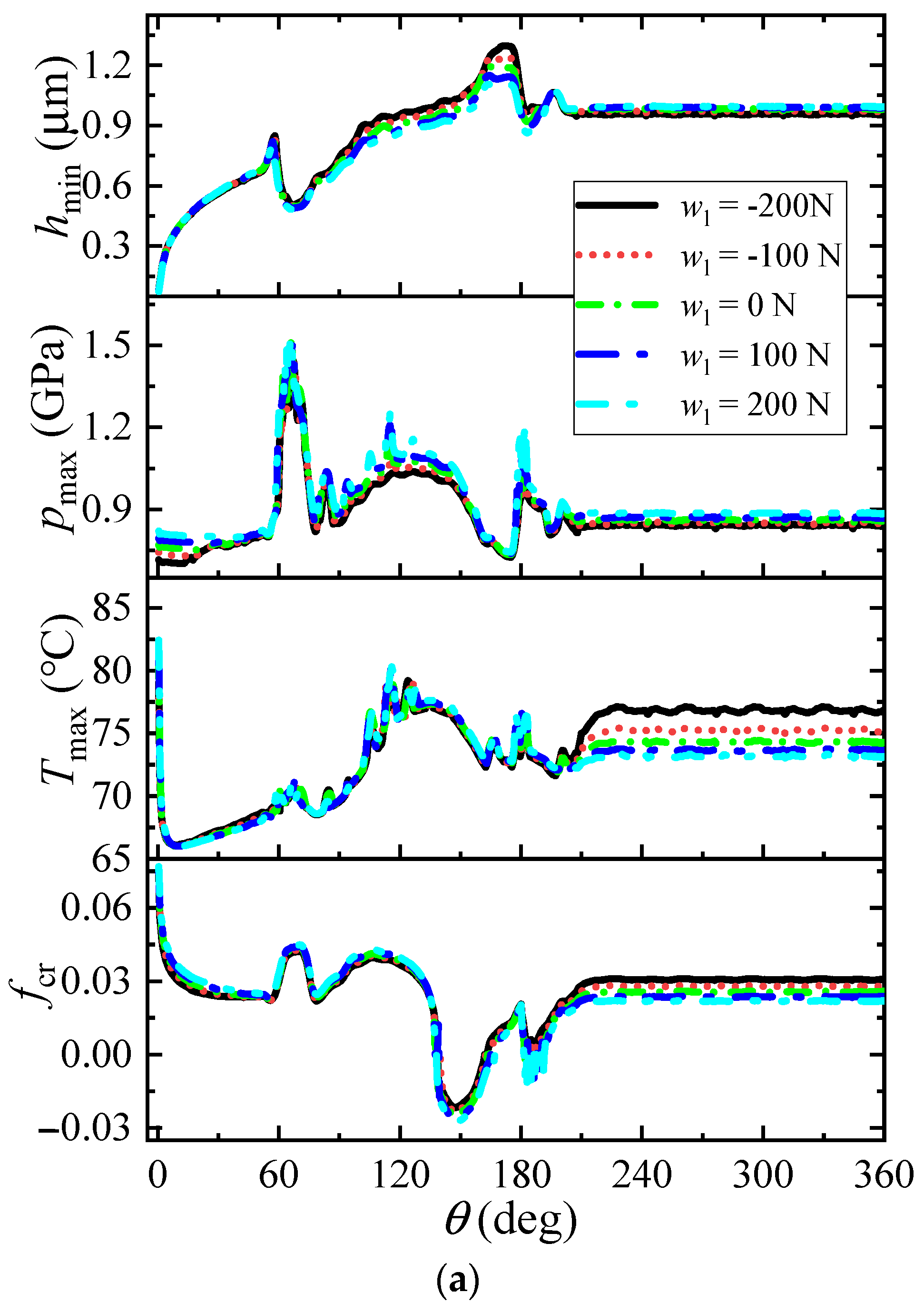
Figure 13 shows the variation of the slide-roll ratio as a function of the modified load at three special angles (0°—located in the cam base circle part and 100/176°—located at the convex peak of the slide-roll ratio in the non-cam base circle part). It can be seen that at the three cam rotation angles, the slide-roll ratio decreases as the modified load increases. When the modified load increases, the friction coefficient in the contact zone decreases (
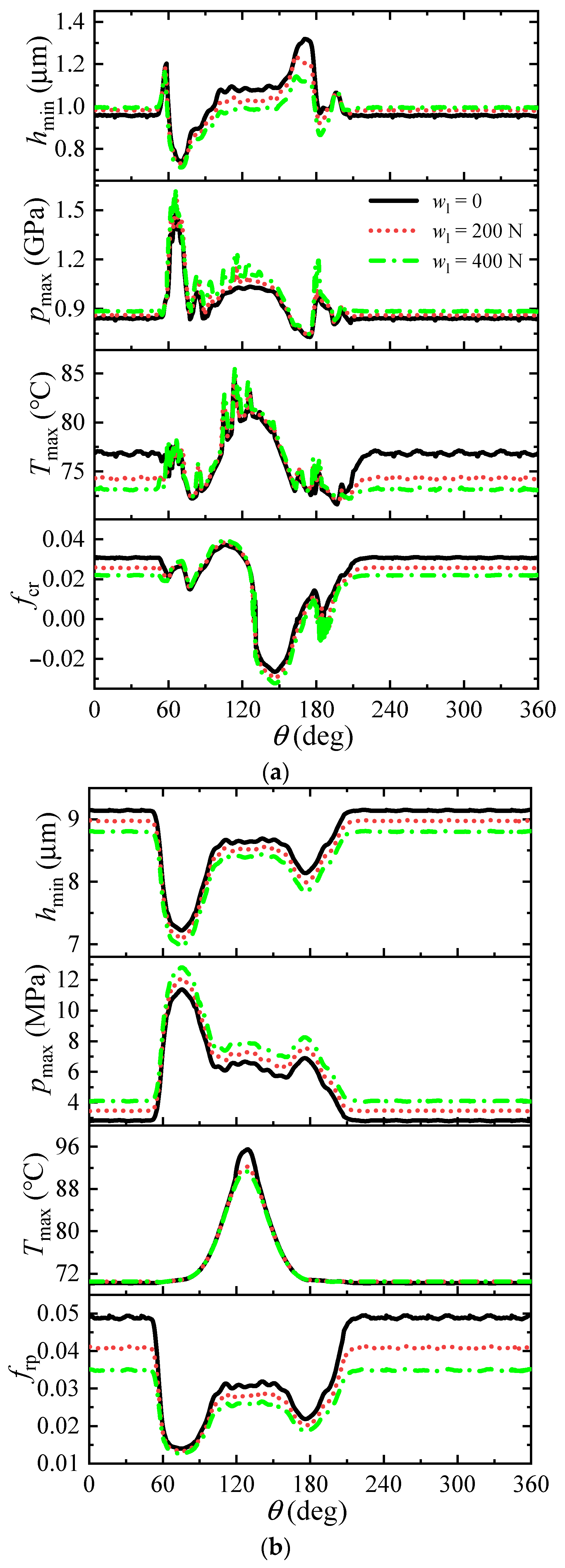
Figure 14), and the surface sliding value between the cam and the roller decreases. Due to the relatively small initial load in the cam base circle part, a certain amount of modified load accounts for a large proportion of the total contact load. However, the proportion of modified loads is relatively small in the non-cam base circle part. Consequently, the change in slide-roll ratio is large at 0° and relatively small at 100/176°. Similarly, the changing curvature gradually decreases with increasing modified loads, especially at 0°. In order to reduce the degree of skidding, a larger initial load should be chosen. However, the increase in the contact load will lead to a decrease in the film thickness and an increase in the pressure in the cam-roller unit (
Figure 14), which is unfavorable to the lubrication state. Therefore, the initial load can be increased to improve the skidding condition, but it cannot cause an oil film rupture or severe pressure concentration in the contact zone.
4.2. Skidding at the Startup Running Process
The startup process of the internal combustion engine is an inevitable part of its operation. Therefore, the cam-roller unit must undergo a startup running process where the cam drives the stationary roller to accelerate to the rated speed. This study analyzes the skidding situation in this process by considering that the camshaft starts with a constant angular acceleration and reaches the rated cam rotational speed (
nc) at 180°.
Figure 15 shows the variation of the cam surface velocity, where the accelerated rotation stage is 0–180° and the constant rotation stage is 180–360° during the startup running process.
The slide-roll ratio between the cam and the roller is plotted under the steady/startup running conditions of
η0 = 0.152 Pa · s and
w1 = 0 N (
Figure 16) to understand the characteristics of skidding during the startup process. It can be clearly seen that the skidding situation during the acceleration stage of the startup running process is different from that in the steady running process, but similar to the situation in the constant speed stage. This is related to the lubrication state of the cam-roller unit (
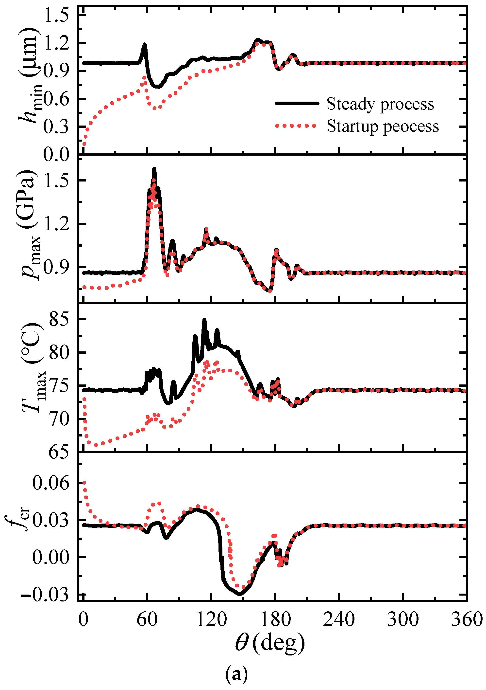
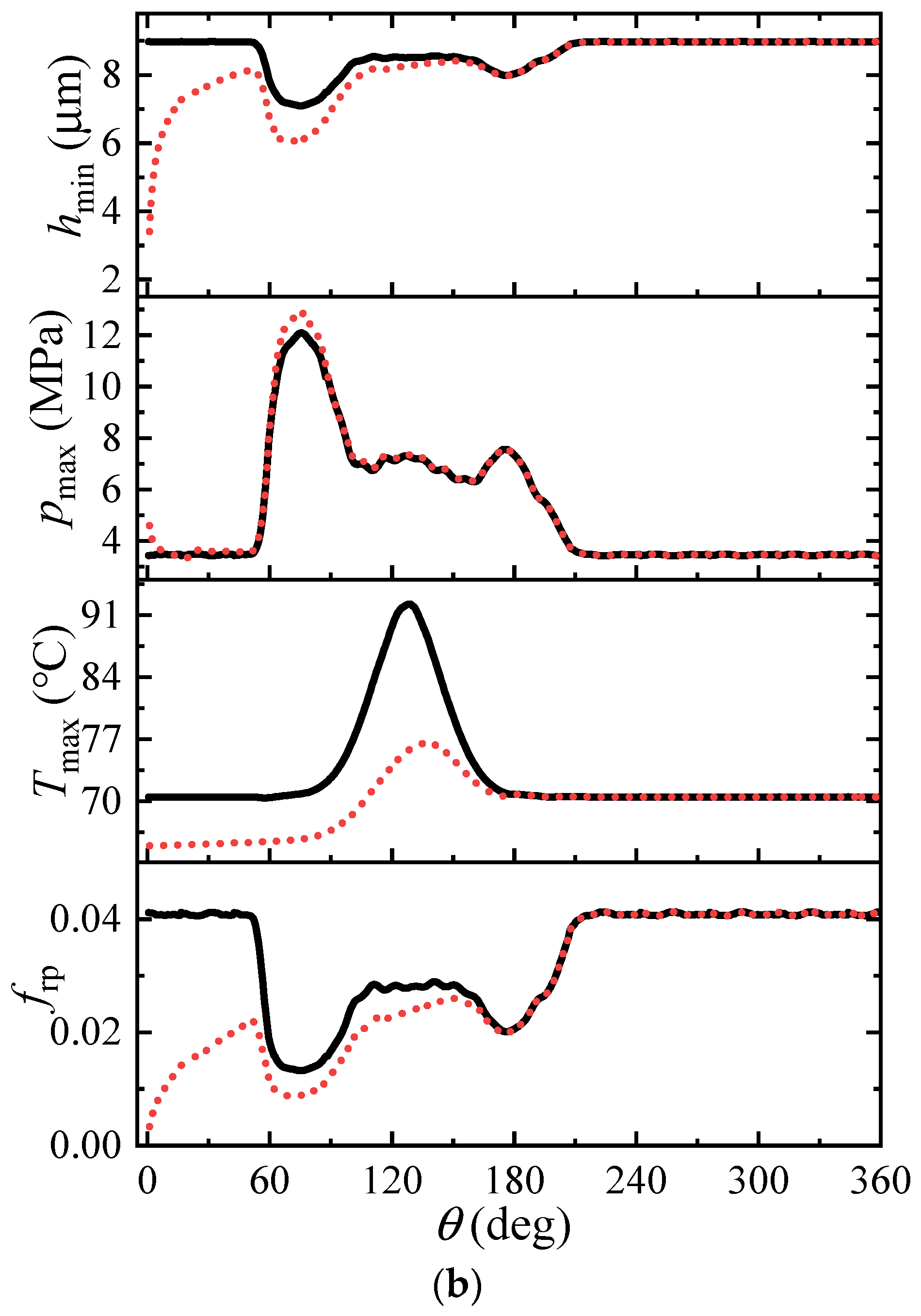
Figure 15). At the beginning of the startup stage (0–18°), the difference in slide-roll ratio is greater than 50% because the cam needs to drive the stationary roller to start moving. Although a large slide-roll ratio produces a large roller driving torque (that is, a large friction coefficient
fcr in
Figure 17), it cannot realize the synchronous acceleration of the cam and the roller. However, it can gradually reduce the slide-roll ratio. In addition, a lubrication film is formed in two contact zones, and its thickness gradually increases. Within the cam rotation angle of 34–54°, the slide-roll ratio during startup is slightly lower than that in steady process (the difference is less than 5%). This may be due to the cam and the roller reaching a relatively stable state before entering the cam opening ramp. During the acceleration stage, the roller has a relatively lower rotational speed than that in the steady running condition, which indicates that the impedance torque (see from
frp in
Figure 17) and the moment of inertia exerted on the roller are small. Therefore, the driving torque generated by the relatively small slide-roll ratio can achieve the desired acceleration. The change in working conditions then breaks the dynamic balance of the cam-roller unit, making the slide-roll ratio higher than that in the steady running process again. As the cam speed gradually approaches the rated speed, the gap between the slide-roll ratio and the lubrication state in the two conditions also gradually decreases. When the cam rotation angle exceeds 180°, the conditions for steady and startup processes are the same. That is, the slide-roll ratio and the lubrication state in the cam-roller unit are no longer different. In general, skidding is more obvious during the startup running process, especially at the beginning of the acceleration stage, where skidding is very severe and the lubricating oil film thickness is small.
4.2.1. Effect of Oil Viscosity
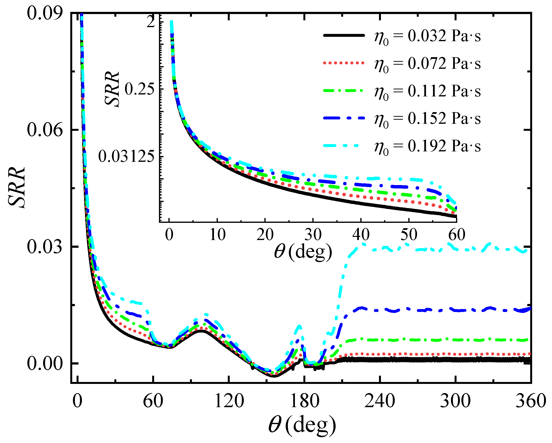
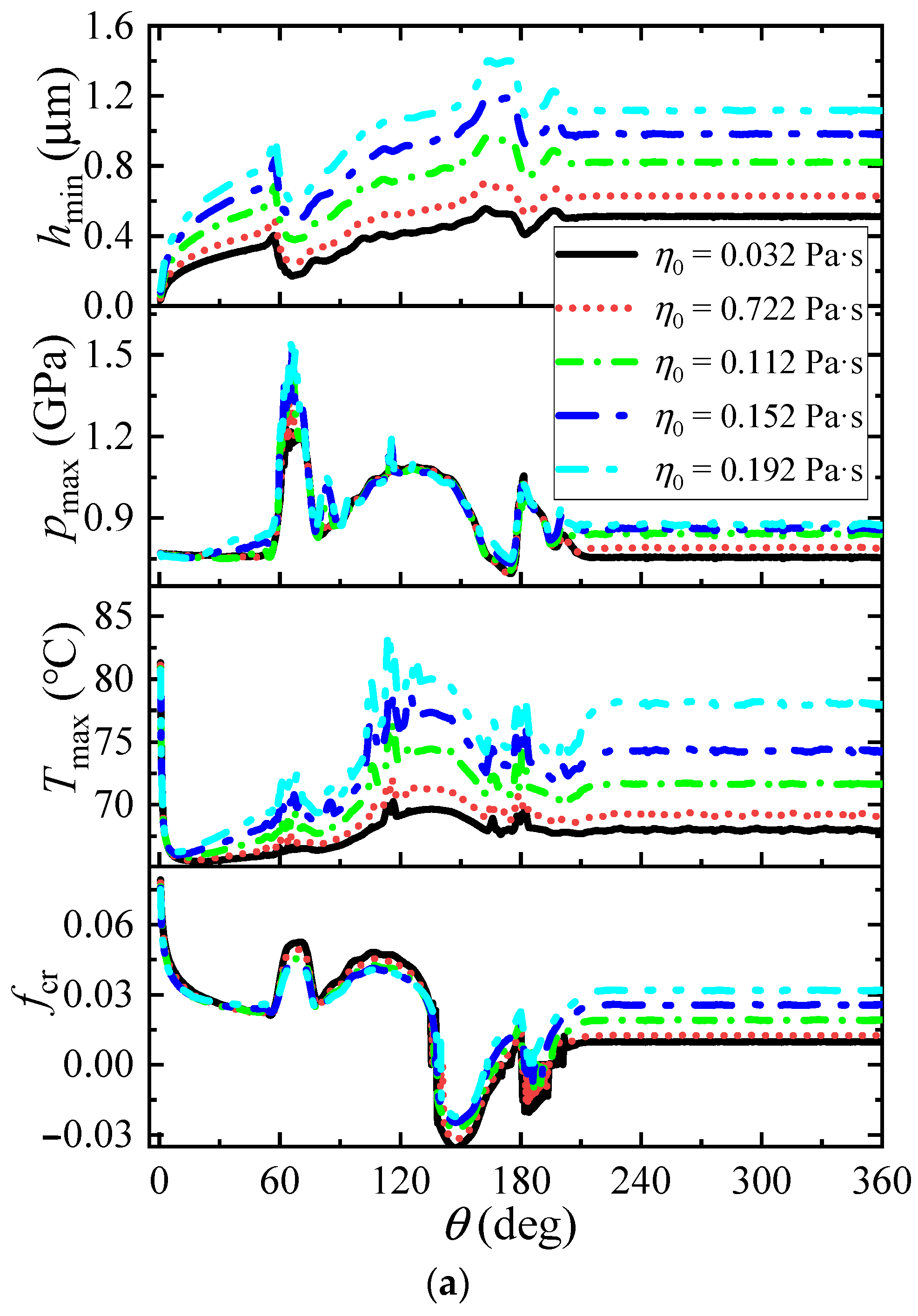
Figure 18 shows the effect of oil viscosity on the slide-roll ratio during a complete cam rotation at startup and steady running. It can be seen that the change of the slide-roll ratio in the range of 0–7° is hardly affected by the oil viscosity. At this time, the roller has just started to move from its stationary state. The surface velocity of the cam and roller is relatively small. The effect of viscosity has not been highlighted. Afterwards, as the cam continues to accelerate, the curves of the slide-roll ratio start to show significant differences at different oil viscosities. The larger the oil viscosity, the greater the slide-roll ratio. This can be attributed to the fact that oil viscosity affects the friction coefficient
frp of the roller-pin contact (
Figure 19). High viscosity can increase the impedance torque of the roller. It is worth mentioning that during the steady running process, this is consistent with the previously discussed influence of oil viscosity, and the effect of oil viscosity is higher than that in the startup process.
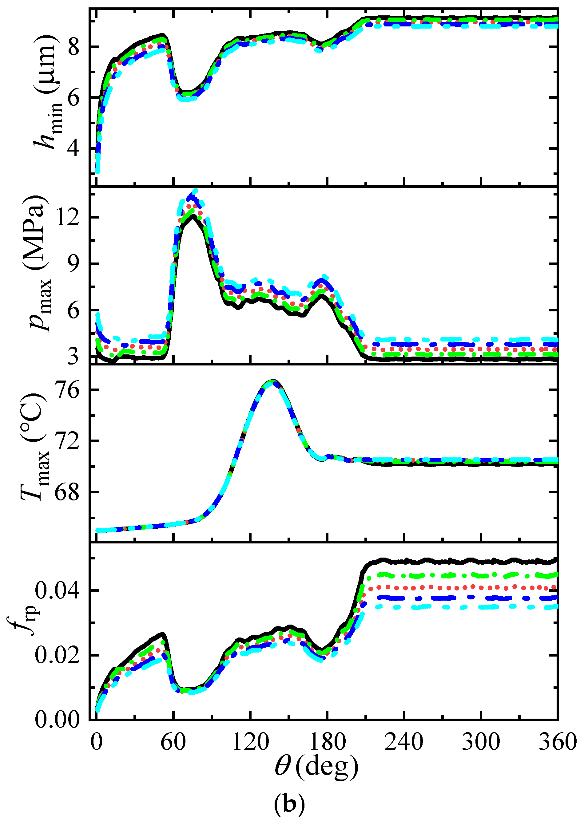
In addition, by comparing the two stages of 0–180° and 180–360°, it can be deduced that the influence of oil viscosity on skidding in the accelerated rotation stage is significantly weaker than that in the rated rotation stage. This is directly related to the lubrication state of the cam-roller unit (
Figure 19). During the acceleration stage, the cam speed is relatively low, which mainly leads to a small film thickness and a temperature increase in the cam-roller unit. The lubrication state is less sensitive to oil viscosity. In addition, the friction coefficient of the roller-pin contact is lower than that of the constant rotation stage. This results in a reduced influence of oil viscosity on skidding during the acceleration stage. Therefore, oils with low viscosity should be used to reduce skidding on the premise that an effective lubricant can be formed quickly in the contact area.
4.2.2. Effect of the Modified Load
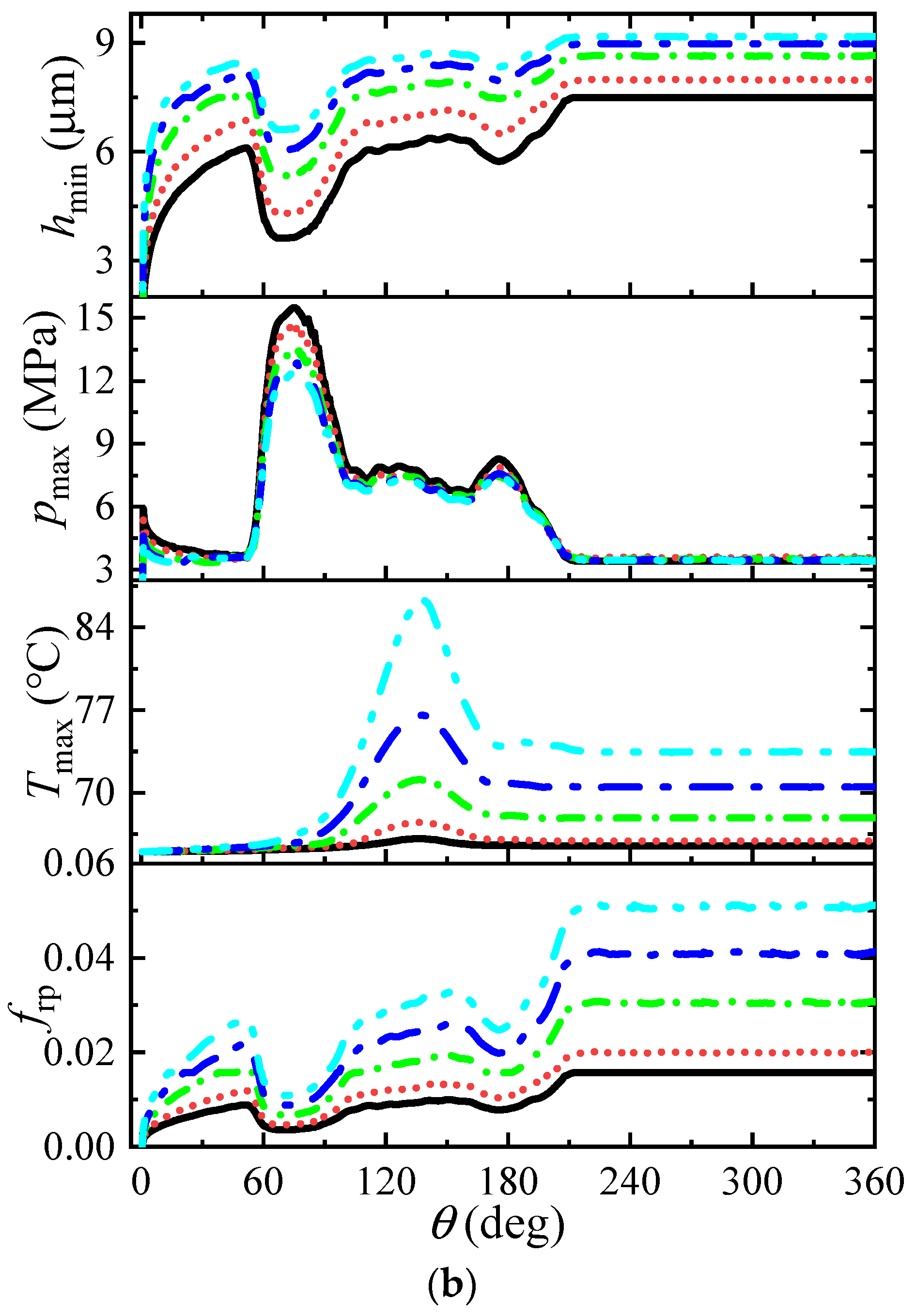
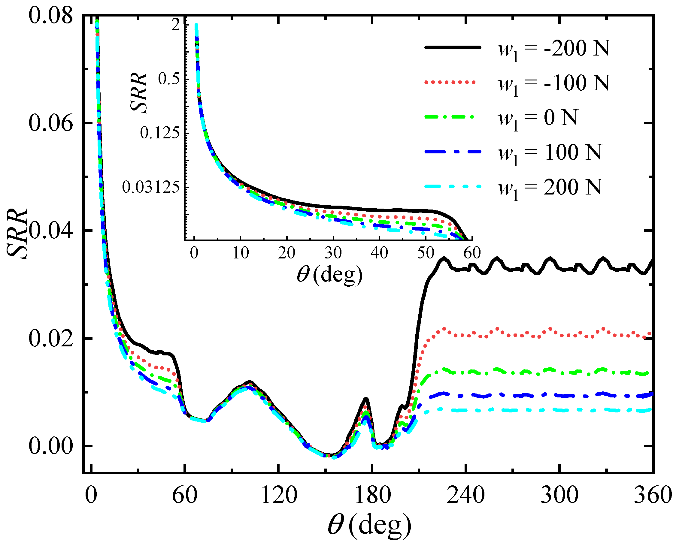
Figure 20 shows the impact of a modified load on the slide-roll ratio in a complete cam rotation during the startup running process. It can be seen that increasing the modified load can reduce the skidding between the cam and the roller to a certain extent. Similar to the oil viscosity effect in the previous section, the modified load hardly affects the slide-roll ratio at the beginning of the accelerated rotation stage (0–7°). Skidding depends on the fact that the roller is initially stationary. In the range of 7–58°, the impact of a modified load on the slide-roll ratio is more obvious. However, the degree of this impact gradually weakens with the increase in the modified load. At this stage, skidding is greatly reduced and easily affected by the working conditions. Relatively low initial load conditions are more susceptible to modified loads. Similarly, after entering the high contact load stage, skidding is only slightly affected by the modified load. Compared with the constant rotation stage, skidding in the acceleration stage is less affected by the modified load. This is due to the different sensitivities of the lubrication state to the modified load in the two stages, especially the friction coefficient of the roller-pin contact (
Figure 21). It is worth mentioning that the maximum pressure increases with the modified load throughout the startup and running processes. Pressure can be considered a constraint on the selection of the initial static load. Therefore, a relatively larger initial load should also be considered within the safe range of the allowable contact force to reduce skidding during the startup running process.


