Article

Static Stiffness Properties of High Load Capacity Non-Pneumatic Tires with Different Tread Structures

1
State Key Laboratory of Automotive Simulation and Control, Jilin University, Changchun 130025, China
2
Feynman Technology (Qingdao) Co., Ltd., Qingdao 266000, China
*
Author to whom correspondence should be addressed.
Lubricants 2023, 11(4), 180; https://doi.org/10.3390/lubricants11040180
Submission received: 12 March 2023 / Revised: 12 April 2023 / Accepted: 12 April 2023 / Published: 18 April 2023

Abstract

:
A high load capacity non-pneumatic tire (HC tire) was designed and manufactured to solve the problems of air leakage, puncture, blowout, shoulder void, and delamination, which occur in traditional high load capacity tires, as well as significantly increase the unit load of tires. Experiments and numerical simulations were conducted to investigate the static stiffness properties of the HC tire. Additionally, the manufacturing process of the tire was highlighted. The tire mainly comprised polyurethane and silicon manganese steel, and a ‘π’-shaped support substructure was adopted. The tread structure was made up of a built-in spiral steel ring and a non-steel ring. The uniaxial tensile mechanical properties of the used metal and elastomer materials were tested, and the linear elastic constitutive model and Marlow constitutive model, respectively, were used to describe their mechanical characteristics. The stiffness properties of the HC tire, including torsional, longitudinal, vertical, and lateral stiffnesses, were evaluated using a tire comprehensive stiffness tester. Nonlinear finite element models of the HC tire were established, and their accuracies were verified through vertical stiffness tests. The stiffness properties of the HC tire in other directions were simulated as well. An in-depth comparative analysis of the simulation and experimental data was performed. The results demonstrated that the unit load of the unreinforced HC tire was 2.972 times and 1.615 times higher than that of the solid tire and pneumatic tire, respectively. The spiral steel ring embedded in the tread increased the vertical and longitudinal stiffness but reduced the torsional stiffness of the HC tire, thus reversing the variation trend of the lateral stiffness at the 0° and 5° test points. The findings can serve as a reference for theoretical research on, and the structural optimization of, non-pneumatic tires with a high load capacity.

1. Introduction

Tires are crucial automobile components. Its basic functions include supporting the vehicle weight, transmitting driving and braking torque, providing vibration absorption and envelope capacity, and ensuring cornering stability. In addition, tires should possess performance characteristics such as abrasion resistance, low rolling resistance, durability, and safety [1]. In contrast to rigid wheels, pneumatic tires have dominated the global tire market for decades due to the following advantages: low contact pressure, low energy loss, low mass, and low vertical stiffness. However, they have several disadvantages, including complicated manufacturing procedures, difficulty maintaining proper internal air pressure, and susceptibility to a flat during driving [2]. Major tire manufacturers and research institutions have developed run-flat tires and non-pneumatic tires (NPTs) to ensure a consistent inflation pressure and avoid punctures, thus securing tire performance and driving safety. The stiffness characteristics and contact pressure of pneumatic tires are dependent on the inflation pressure, whereas the behaviors of NPTs are influenced by the structural and material designs of the support structure and shear bands, which expands their design space.
NPTs were first conceived by the Michelin company in 2005. Rhyne et al. [3] proposed a non-pneumatic tire/wheel named a Tweel that breaks the shape and size restrictions of traditional tires. It is mainly composed of a tread that contains the shear beam, elastic spoke, and hub. The shear beam consists of elastic materials with a relatively low shear modulus surrounded by two tensile membranes, which act as a substitute for the inflation pressure. Tweels not only have the advantages of pneumatic tires, namely low contact pressure, energy loss, mass, and vertical stiffness, but the torsional, lateral, and vertical stiffnesses are also no longer closely related. Specifically, designing a structure with low torsional and vertical stiffnesses and high lateral stiffness by adjusting the design parameters is facile. Bezgam [4] and Rutherford [5] conducted orthogonal array experiments and established a 2D finite element model (FEM) to study the effect of geometric parameters and spoke angle on ground force interaction and the spoke vibration amplitudes of a Tweel rolling at high speed. The former determined that combining a thick spoke with small curvatures with a thin spoke with large curvatures in alternating spoke pairs of equivalent mass could reduce vibration. The latter determined that the optimal configuration for reducing vibration is a wheel with large curvature and short spokes. Ju et al. [6,7] investigated the in-plane shear and Young’s moduli of auxetic and conventional hexagonal honeycombs made of mild steel and polycarbonate materials for a given honeycomb metamaterial height. This was achieved through a numerical parametric study of an analytical model, in which the flexible shear characteristics were evaluated by varying the cell wall thickness. They then investigated the contact performance of a tire with metallic cellular shear bands, which affected the in-plane shear flexibility, through finite element analysis. Narasimhan et al. [8,9] examined the vertical static stiffness of the Tweel and found that it increased with the shear modulus coefficients of the shear bands in the material constitutive model. Ma et al. [10] studied the strain (stress) between soil and treaded NPTs with varying shear bands of different cell geometries through finite element analysis and determined the appropriate cell angle, cell height, and leg length.
Rugsaj et al. [11,12,13,14,15,16] conducted a systematic study of the Tweel. The material parameters of the spokes were determined via a three-point bending test and uniaxial tension and compression tests, and the precision of the material constitutive was confirmed through simulation. A 3D FEM was established, and its accuracy was verified via vertical stiffness tests; the appropriate thickness of the spoke was obtained through simulation. Moreover, a 3D transient dynamic FEM was established, and its precision was validated by comparing the spoke deformations. The wheel was found to have a higher reaction force, deflection, and stress than static load when rolling. Uniaxial tensile tests were conducted under different loading conditions to study the ultimate stress and fracture strain of 3D printed specimens and sliced spoke specimens.
The honeycomb tire was developed by Resilient Technologies in the United States in 2007. The spoke uses a flexible high-performance material, which has the advantages of high elasticity and fast heat dissipation while maintaining strength. Kim et al. [17] determined that the vertical stiffness of NPTs decreased with vertical load due to the high initial resistance to cell wall compression and subsequent susceptibility of the cell walls to buckling. Veeramurthy et al. [18] investigated the effects of the shear modulus of polyurethane and the thickness of the shear band and spokes on the contact pressure, vertical stiffness, and rolling resistance of NPTs through sensitivity analyses, design of experiments (DOE), and parametric studies. They minimized the energy loss under contact pressure and vertical deformation constraints by properly designing the parameters obtained through a response surface model. Meng et al. [19] performed a range of stiffness and degrees of freedom analyses on NPTs with the honeycomb structure under identical vertical loading conditions through simulation. They designed cross-arcs and rectangular cells through a synthetic design method, which leverages compliant mechanism principles, and an improved design method was applied to the existing honeycomb structure. Zang et al. [20] designed a circular and hexagonal honeycomb structure based on the tangent method. They studied the contact pressure, radial stiffness, and displacement rules in honeycomb structures of different densities and analyzed the bearing performance of NPTs through simulations performed under static conditions. The findings revealed that when the honeycomb density increases, its radial stiffness also increases. Jin et al. [21] studied the dynamic and static characteristics of NPTs with varying honeycomb spokes and discovered that NPTs had not only much lower maximum stresses than pneumatic tires, but also a higher load-carrying capacity. Papaeorgiou et al. [22] performed a parametric FEM by considering a wide range of internal geometrical parameters to evaluate the maximum vertical displacement, contact pressure, energy absorbed, and maximum stress during the vertical loading of NPTs. The results revealed that the internal angles, thickness, and density of cells strongly affected the vertical stiffness. To identify appropriate fatigue-resistant honeycomb structures for NPTs, Ju et al. [23] designed auxetic and regular cellular spoke geometries using honeycomb mechanics and investigated their local stresses under uniaxial loading through finite element analysis. Aboul-Yazid et al. [24] investigated the differences in the structures of Bridgestone NPTs, Resilient Technologies’ tires, and Michelin’s Tweel through two-dimensional analysis under quasi-static conditions to determine how the rolling resistance, stress masses, vertical stiffness, and contact pressure are influenced by the shear layer and different support structures.
Zhao et al. [25,26] created a mechanical elastic wheel composed of a suspension hub, hinge units, and flexible tire body. A nonlinear FEM was established to study the displacement and stress distribution of the soil and wheel. Moreover, the effects of different rotational speeds on the displacement, velocity, and acceleration of the hub center were discussed. Zhao et al. [27] compared the effect of errors during installation and processing on the vertical stiffness and observed a good consistency among the bench test results, interval finite element simulations, and interval mathematical analysis. Wang et al. [28] analyzed the relations between the excitation frequency, laminated structure parameters, elastic stiffness of hinges, bending stiffness of the wheel, and radial deformation by applying the governing differential equations with boundary conditions and the Laplace transformation. The results indicated that the effect of the equivalent stiffness on the dynamic response was identical to that of the deformation and laminated structure in the elastic wheel. Wang et al. [29] evaluated the feasibility of using fused deposition modeling (FDM) technology to 3D print non-pneumatic tires based on thermoplastic polyurethane (TPU) materials. They studied the influence of 3D printing process parameters based on FDM technology on the performance of molded products through tensile testing and SEM observation, and obtained the optimal 3D printing temperature of the applied material. Additionally, they tested the vertical, lateral, and longitudinal stiffness of the 3D printed NPT.
At present, research on NPTs is focused on small tires with a low loading capacity, most of which are made of polymer elastomer materials. In this study, a high load capacity NPT was designed and manufactured to meet the high carrying capacity needs of special application scenarios; for example, the HC tire can be applied to some automated guided vehicles whose single tire maximum bearing capacity is 39.2 kN in ports, and military vehicles with the requirement of bullet impact resistance. The primary contents of this study are structural design, manufacturing, material mechanical characteristic test, finite element analysis, and tire bench tests of the HC tire. The accuracy of the FEM was verified, and the static stiffness properties of an HC tire with different tread structures were analyzed.

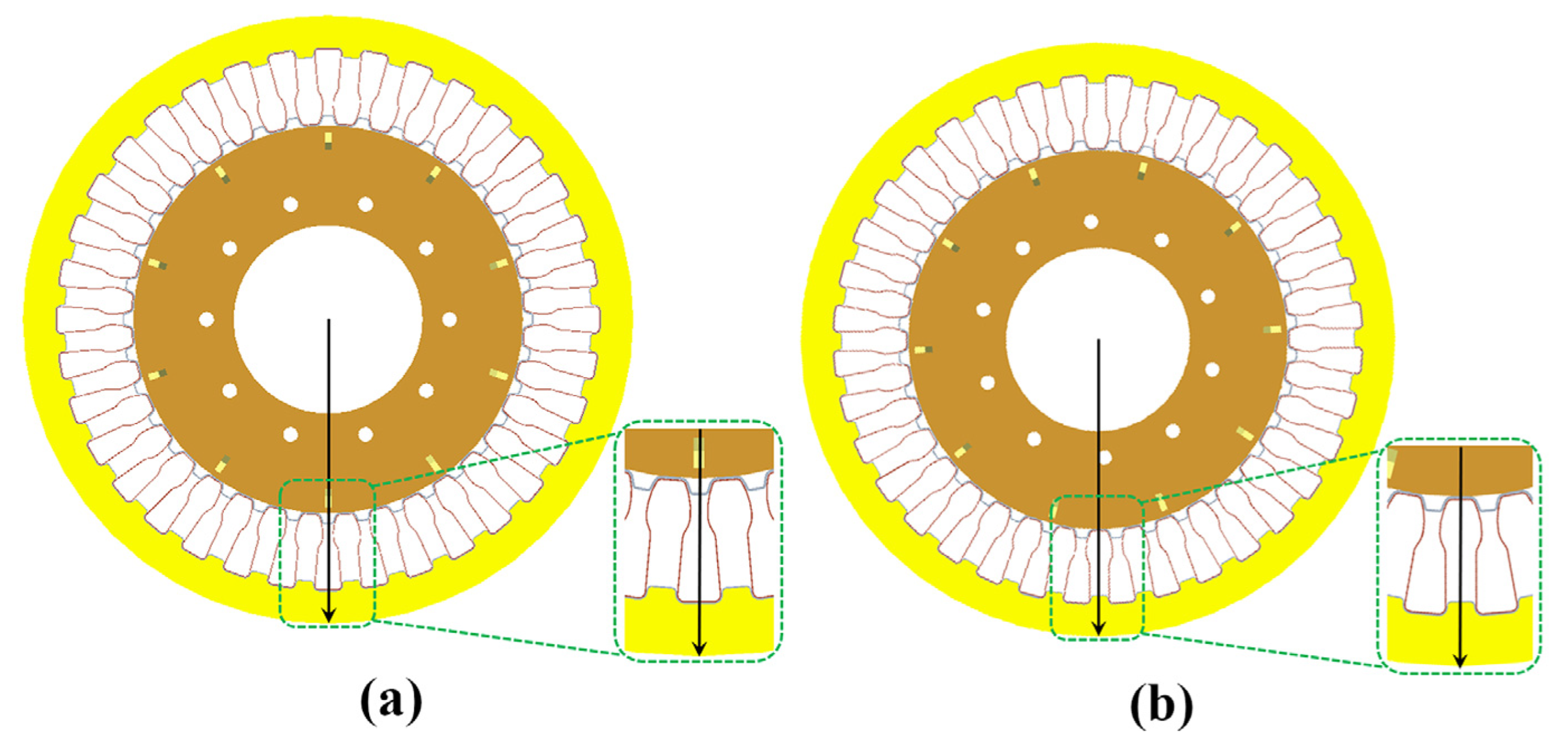
2. Structure of the HC Tire

The HC tire was composed of a wheel, an inner concave–convex structure, ‘π’-shaped support substructures, an outer concave–convex structure, a tread, and a spiral steel ring, as shown in Figure 1. The wheel adopted an I-shaped structure, and 10 pairs of reinforcing ribs (141) were uniformly distributed along the circumference (130). The support structure was composed of 36 similar ‘π’-shaped substructures (142) arranged along the circumference, which bear a large part of the load. Further, 36 inner concave–convex substructures (143) and 2 outer concave–convex substructures (144) were circumferentially arranged along the inner (132) and outer (131) radial sides of the HC tire, respectively, mainly to induce the deformation of similar ‘π’-shaped support substructures. The spiral steel ring made by winding forming was horizontally arranged along the tire to enhance the tread and transfer the load. The tread was poured from thermosetting polyurethane material, and the spiral steel ring was evenly prepositioned in the mold. The design parameters of the HC tire, such as diameter and section width, were benchmarked against a 12.00R20 truck tire with a width of 315 mm and an outer diameter of 1135 mm, whereas the wheel had an inner diameter of 350 mm and an outer diameter of 722 mm, as displayed in Figure 2. The thicknesses of the inner concave–convex substructures, similar ‘π’-shaped substructures, and outer concave–convex substructures were 3 mm, 1.65 mm, and 2 mm singly. The cross-section diameter of the spiral steel ring was 10 mm, and its outer diameter was 1185 mm. The thickness of the convex and concave part of the tread was 77 and 55 mm, respectively.

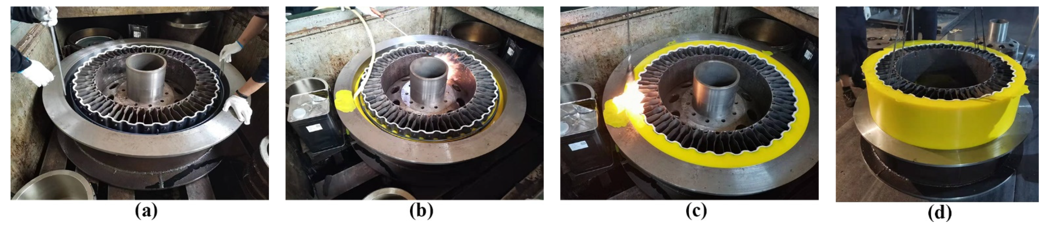
3. Manufacturing Process of the HC Tire

Manufacturing the HC tire mainly involves forming the parts and the interface connection between the parts. The inner concave–convex, outer concave–convex, and support structure were made of silicon–manganese spring steel, the hub was made of wheel steel, and the tread was made of thermosetting polyurethane.
The inner concave–convex, outer concave–convex, and support structure were manufactured through cold plate bending forming and heat treatment. One-bending, three-bending, and continuous-bending forming processes were applied to the inner concave–convex structure, support structure, and outer concave–convex structure, respectively. The final products are shown in Figure 3. The springback phenomenon of the sheet after bending should be considered when designing the die, and a suitable springback angle should be selected to ensure bending accuracy. Before bending forming, the steel plate was preheated to improve the material microstructure, eliminate the internal stress, and improve the bending performance of the sheet. After forming, the workpiece was quenched and tempered to meet the requirements of hardness, toughness, and plasticity. Further, the hub was manufactured through rolling and welding.
The interface connection of metal parts was formed through metal surface treatment and resistance spot welding. A bolt connection between the outer concave–convex structure and support structure was used. The hub, inner concave–convex structure, and support structure were connected through resistance spot welding, as shown in Figure 4, which involves the welding of multilayer dissimilar steel plates of unequal thickness. Before welding, the metal surface should be pickled to ensure the workpiece surface meets the welding requirements. Moreover, the welding pressure, welding current, welding time, and cooling time in the preheating, welding, and tempering steps should be reasonably set to ensure that the positive tensile strength and shear strength of the solder joint meet the requirements.
Tread forming involves metal surface treatment and pouring. Before pouring, the surfaces of the spiral steel ring and outer concave–convex structure were sandblasted and sprayed with bottom and outer adhesives to ensure adequate bonding strength between the applied thermosetting polyurethane, whose density is 1.13 g/ cm 3 , and the metal. After the spiral steel ring and assembled metal parts were positioned in the pouring mold and heated together, a uniformly mixed prepolymer and curing agent were injected into the mold cavity, and the mold was released after it was completely cured, as shown in Figure 5. After tread demolding, secondary vulcanization was performed for 16 h to ensure the polyurethane hardness fully met product requirements.
Rubber materials in traditional tires can be recycled, which are otherwise hard to dispose of [30]. The end-of-life tires are cut and crumbled to rubber particles of various sizes: granulate, fibers, grit, or powder, and then thermally processed. The rubber particles can be used as materials for, for example, car floor mats, under ballast mats, vibration isolation elements, soundproof coverings, or playground pavements. Similarly, thermoset polyurethane can also be recycled [31]. The main recycling route for thermoset polyurethane is to grind it down to a fine powder and use it as filler in new molding compounds. For instance, the polyurethane recyclable granules obtained from end-of-life NPTs are compounded with polyester resin for compression molding to manufacture bulk molding compound, in which the recyclable granules make up 70% of the weight, and the other 30% is the resin binder.

4. Experiments

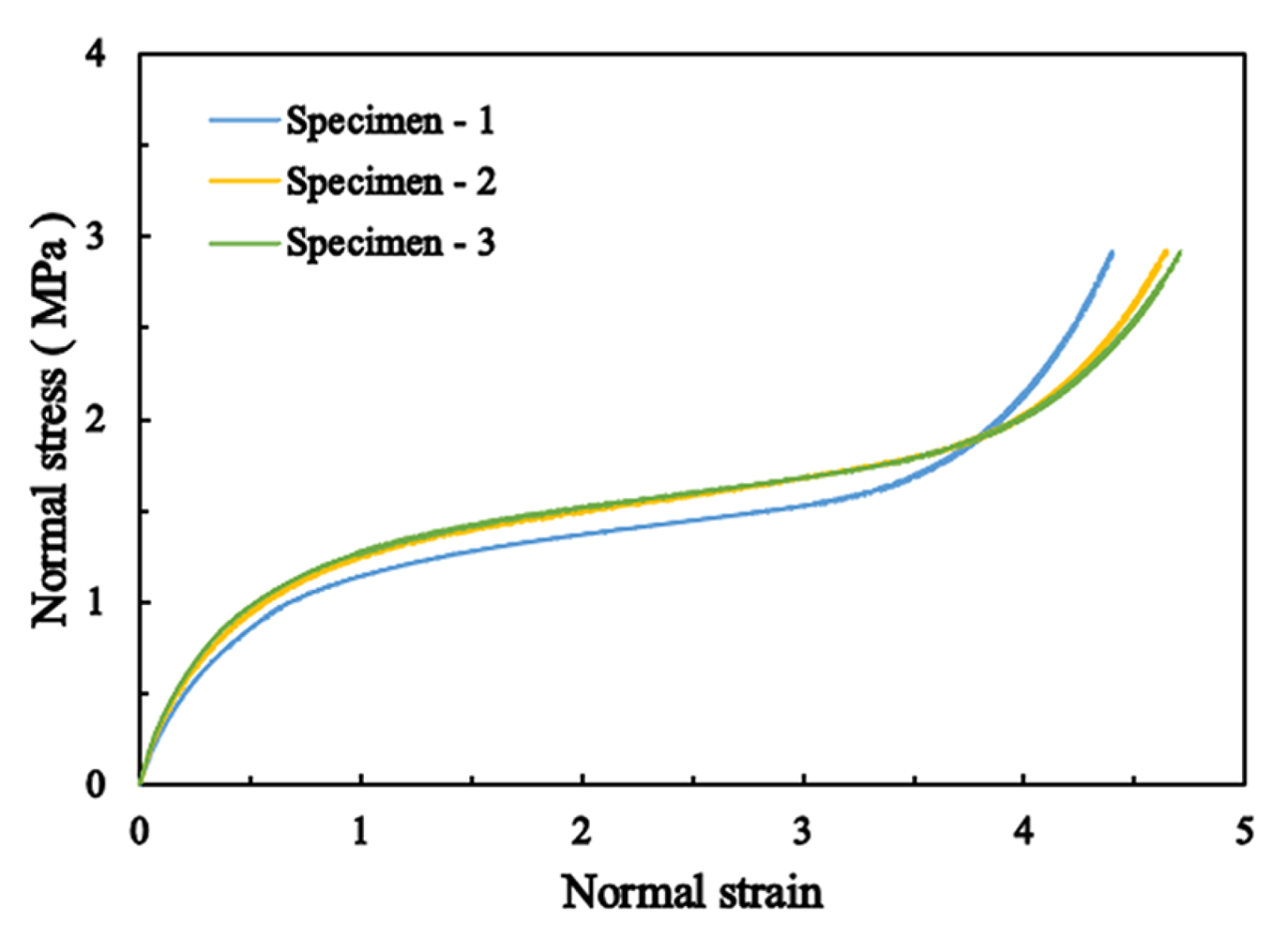
4.1. Tests on Mechanical Properties of Metal and Thermosetting Polyurethane

Building an FEM of the HC tire requires accurately determining the mechanical properties of materials. Three dumbbell-shaped tensile specimens were cut from the inner concave–convex substructures and wheel by wire-electrode cutting, clamped onto an electronic universal testing machine, and fitted with a strain gauge, as displayed in Figure 6a,b. Referring to GB/T 228.1-2010 [32], tests on the uniaxial tensile mechanical properties were performed at a machine displacement speed of 2 mm/min. The mechanical properties of the metal materials are listed in Table 1.
The mold was designed, and the polyurethane tensile specimens were poured, after which the specimens were clamped on the rubber universal testing machine and fitted with a strain gauge, as shown in Figure 6c,d. Tests on the uniaxial tensile mechanical properties were conducted at a machine displacement speed of 500 mm/min, as per HG/T 3849-2008 [33]. The stress–strain curves of the polyurethane specimen are shown in Figure 7.

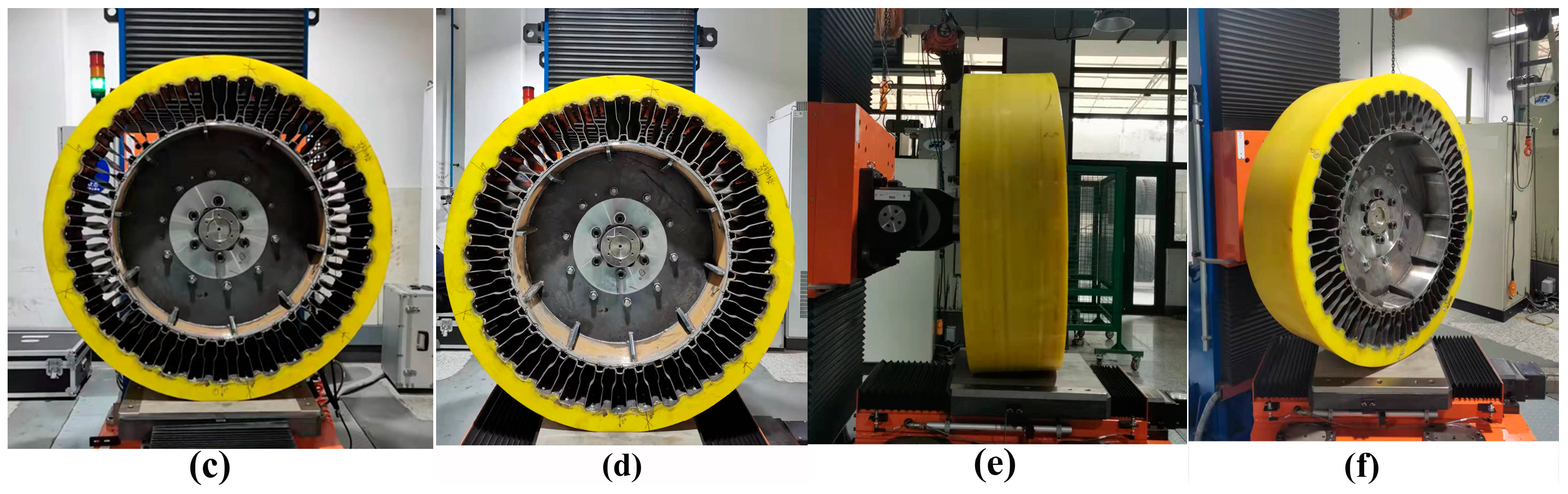
4.2. Static Stiffness Test of the HC Tire

Stiffness is a critical index of tire performance, and the stiffness test is important for determining if the tires meet requirements. Referring to GB/T 23663-2020 [34], the static vertical, lateral, longitudinal, and torsional stiffness tests of the HC tire were conducted on the GDJ-4 tire comprehensive stiffness tester, whose maximum vertical test load, maximum lateral and circumferential test load, and maximum torque were 100 kN, 50 kN, and 3000 Nm, respectively. As displayed in Figure 8a,b, three sets of test positions were uniformly selected along the circumference of the HC tire, each containing 0° and 5° test points. The load rating of the HC tire was 110.25 kN. However, due to limits in the maximum vertical test load of the test machine, the vertical, lateral, longitudinal, and torsional stiffness tests were performed on each test point at vertical loads of 7.35 kN, 14.7 kN, 22.05 kN, 29.4 kN, 36.75 kN, 44.1 kN, 51.45 kN, 58.8 kN, 66.15 kN, 73.5 kN, 80.85 kN, 88.2 kN, and 95.55 kN.
The bottom plane of the testing machine remained stationary during the vertical stiffness test, and the loading shaft transmitted different vertical loads to the hub center. As shown in Figure 8, the bottom plane of the testing machine executed longitudinal (lateral) motion after different vertical loads were stably applied to the hub center during the longitudinal (lateral) stiffness test. In contrast, when testing the torsional stiffness, the bottom plane of the testing machine rotated in the normal direction after different vertical loads were stably applied to the wheel center. The displacement and force data were collected using machine sensors.

5. Finite Element Model

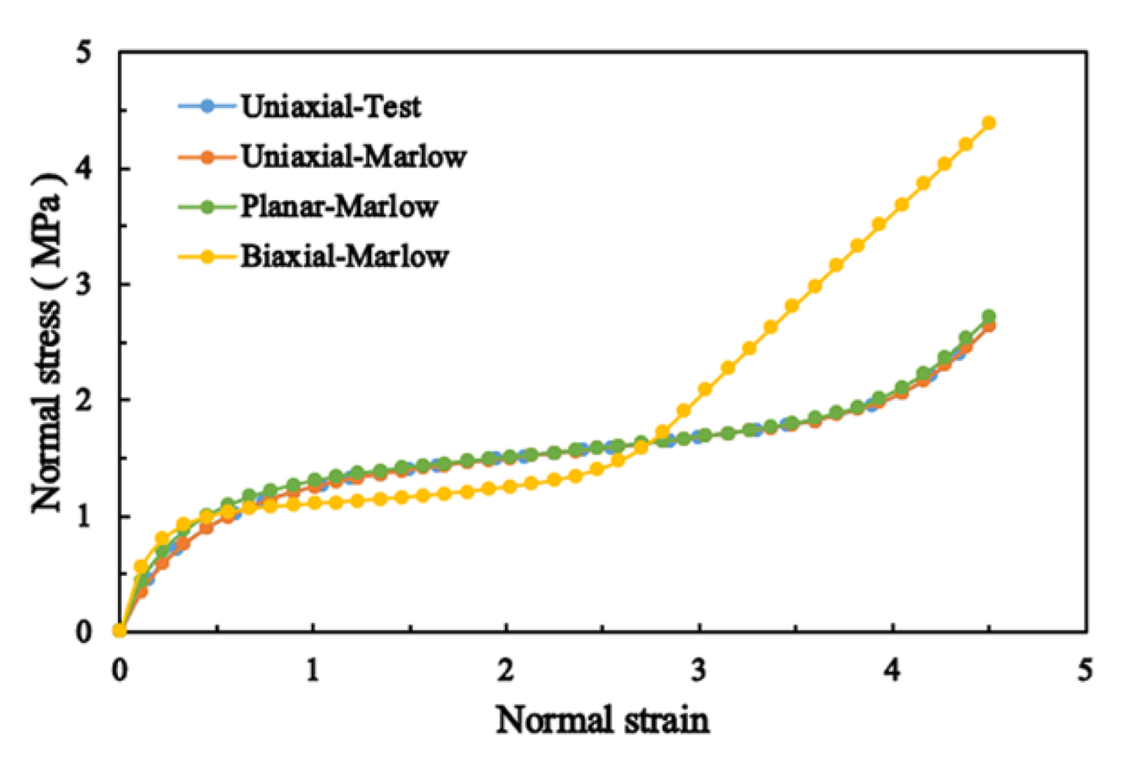
5.1. Material Constructive Model

The strain energy potential U ( E ) , which is defined as the strain energy stored within a unit volume of the material as a function of the strain of the material, is used to describe hyperelastic materials. The ABAQUS finite element software provides a few forms of the strain energy potential for modeling largely incompressible isotropic elastomers: van der Waals, polynomial, reduced polynomial, Ogden, neo-Hookean, Mooney–Rivlin, Marlow, Yeoh, and the Arruda–Boyce forms. The Marlow form is recommended when only one type of experimental data, such as planar, equibiaxial, or uniaxial test data, is accessible. For this case, a strain energy potential that will exactly reproduce the test data and produce reasonable behavior in other deformation modes is established.
The Marlow model assumes that the strain energy potential is independent of the second deviatoric invariant I ¯ 2 . The strain energy potential form of the Marlow model is
U ε = U dev I ¯ 1 + U vol ( J el )
where U ε is the strain energy stored within a unit volume of the material: U vol is its volumetric part, and U dev the deviatoric part. The first deviatoric strain invariant is I ¯ 1 , which is defined as
I ¯ 1 =   λ 1 ¯ 2 +   λ 2 ¯ 2 + λ 3 ¯ 2
where the deviatoric stretches λ n ¯ = J 1 3 λ n . Notably, λ n represents the principal stretches, J is the total volume ratio, and J el is the elastic volume ratio. The deviatoric part of potentials is described by either planar, equibiaxial, or uniaxial test data, whereas the volumetric part is defined from the volumetric test data, which involves specifying the lateral strains or defining the Poisson’s ratio from the test data.
The elastic volume ratio, J el , connects the thermal volume ratio, J th , and the total volume ratio, J :
J el = J J th
J th is given by
J th = ( 1 + ε th ) 3
where ε th is the linear thermal expansion strain obtained from the isotropic thermal expansion coefficient and the temperature.
Figure 9 shows the fitted polyurethane mechanical curves. Noticeably, the uniaxial tensile engineering stress–strain curve (uniaxial-test) is in good agreement with the fitted uniaxial tensile curve (uniaxial-Marlow). The fitted planar tensile curve (planar-Marlow) and biaxial tensile curve (biaxial-Marlow) are consistent with the variation range and trend of elastomer materials under corresponding loading conditions. A linear elastic constitutive model whose parameters are defined with reference to the data in Table 1 is applied to metallic materials.

5.2. Finite Element Model of the HC Tire

The ABAQUS2018 finite element software of Dassault Systemes was used to establish a three-dimensional nonlinear FEM of the HC tire. The FEMs of the entire tire and main bearing parts are shown in Figure 10. For the FEM of the HC tire, the wheel, inner concave–convex structure, outer concave–convex structure, and support structure were meshed using four-node linear reduced integral elements S4R. The spiral steel ring was meshed using eight-node linear reduced integration elements C3D8R. The tread was made of incompressible hyperelastic material, and eight-node linear reduced integral hybrid element C3D8RH was used to avoid volume self-locking. The element number of the HC tire was 345,940, and the number of nodes was 377,082.
In the FEM of the HC tire, the chemical bonding between the tread and outer concave–convex structure, the bolted connection between the outer concave–convex structure and support structure, and the welding connection between the hub, inner concave–convex structure, and support structure were all constrained using Tie. The chemical bonding between the tread and spiral steel ring and the welding connection among the wheel components were constrained by common-node elements. Coupling constraints were set between the characteristic edge nodes of the inner edge of the wheel and the reference point of the wheel center. The interaction behavior between the bottom plane of the testing machine and the tread involves large deformation and nonlinear contact. The bottom plane was regarded as a rigid analytical body due to its deformation being negligible compared to that of the tire. The tread and bottom plane were placed in surface-to-surface contact, and their tangential and normal behaviors were described by the penalty and hard algorithms, respectively. The friction obeyed Coulomb’s law, and the friction coefficient was set as 0.95. The force and boundary conditions of the wheel and analytical rigid body reference points were set according to their conditions in the stiffness test while simulating the static stiffness properties.

6. Results and Discussion

6.1. Validation of the FEM Model

The simulation accuracy of the vertical stiffness properties in the established FEM of the HC tire was verified to ensure the accuracy of the numerical simulation as well as the credibility of the data obtained in the simulation of other working conditions. The vertical displacement of the HC tire at 0° and 5° test points was calculated using the FEM at 7.35 kN increments of the vertical load from 0 to 95.55 kN. Figure 11 shows the measured and simulated vertical displacement of the HC tire under different vertical loads at 0° and 5° test points, which are in good agreement. The absolute error in the simulation compared with the test results is shown in Figure 12. The maximum error in the vertical displacement was 8.72%, and the value was less than 2.5% when the load was greater than 29.4 kN, which verifies the accuracy of the FEM. When the vertical load was small, the metal connection interface in the FEM was closely fitted. However, due to the manufacturing and assembly errors in the metal parts of the physical HC tire, a small gap was present between the connection interfaces, resulting in a large simulation error. As the load increased, the gap gradually decreased until compaction, and the simulation error decreased.

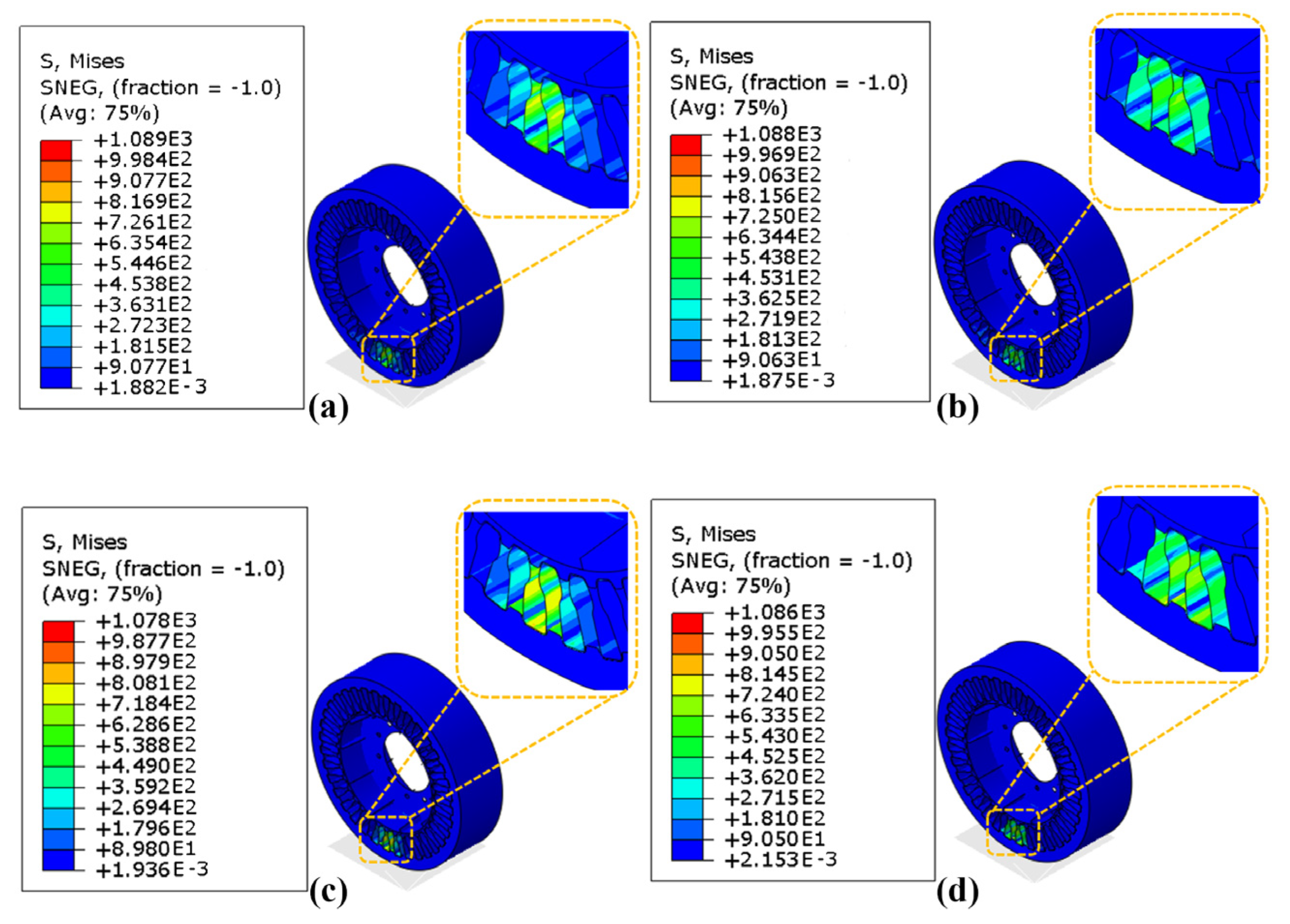
6.2. Unit Load of the HC Tire

As shown in Figure 13, the maximum stress in the support structure was less than the yield strength of the silicon–manganese spring steel when the vertical load on the HC tire was 110.25 kN, revealing that the HC tire meets the bearing requirements. According to the stress nephogram, the bearing mechanism of the HC tire is the bottom bearing. The tire is mainly supported by three support substructures at the bottom 0° test point and two support substructures at the bottom 5° test point.
The design load of the HC tire was 110.25 kN, whereas the maximum load of the 12.00-20 solid tire and 12.00R20 pneumatic tire was 39.2 kN; their weights were 257.8 kg (269.4 kg for reinforced HC tire), 272.2 kg, and 143.8 kg, respectively. Accordingly, their unit loads were 0.428 kN/kg (0.409 kN/kg for the reinforced HC tire), 0.144 kN/kg, and 0.265 kN/kg, respectively. The unit load of the unreinforced HC tire, for example, was 2.972 times and 1.615 times that of the solid tire and pneumatic tire, respectively.

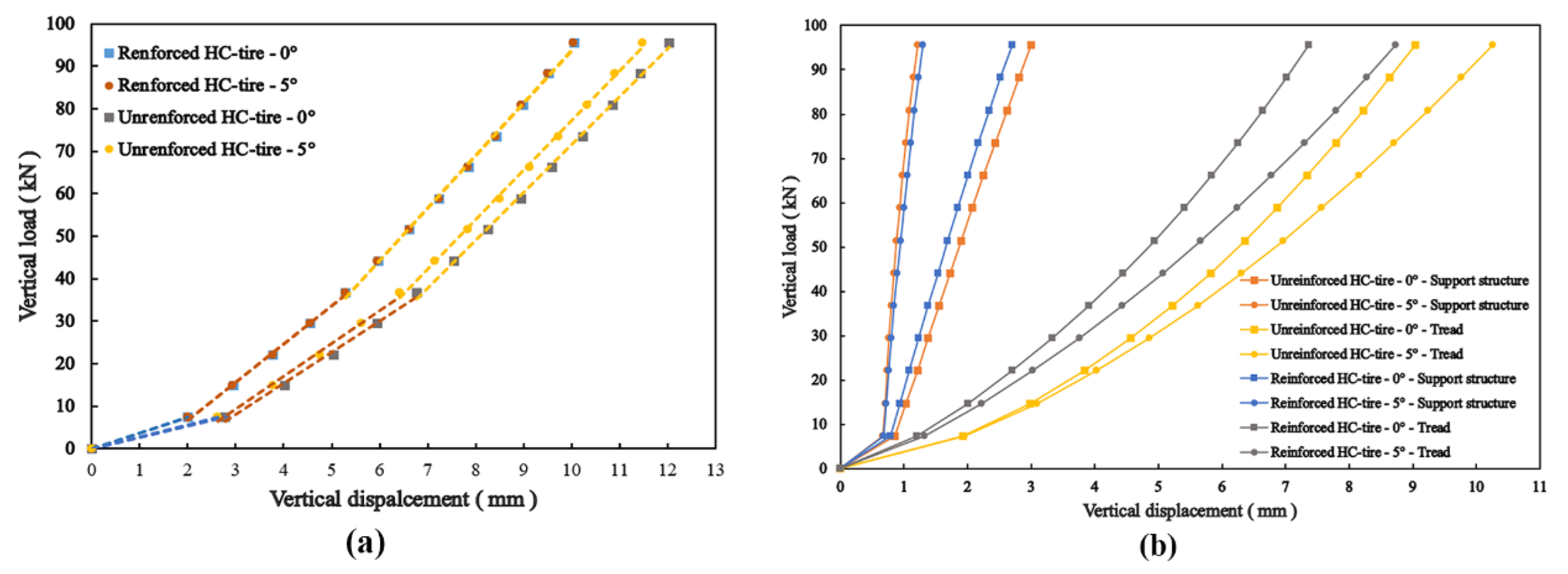
6.3. Vertical Stiffness

The fitting line of the vertical stiffness simulation results of the HC tire is shown in Figure 14a. Noticeably, the inflection points occurred at vertical loads of 7.35 kN and 36.75 kN. The vertical displacement of the support structure and tread are displayed in Figure 14b. The change in the vertical stiffness of the support structure and nonlinear compressive mechanical properties of polyurethane led to the first inflection point of the vertical stiffness of the HC tire, and the support structure had a larger vertical stiffness at the 5° test point. The second inflection point of the vertical stiffness of the HC tire was attributable to the nonlinear compressive mechanical properties of polyurethane. When the vertical load exceeded 7.35 kN, the contact state between the deformed support structure and outer concave–convex structure changed, as shown in Figure 15. A gap was present between the support structure and the induced area of the outer concave–convex substructure before loading. With the increase in vertical load, the deformed support structure and the induced area became connected, resulting in the disappearance of the gap. Accordingly, the support structure deformed, increasing the vertical stiffness of the support structure.
The vertical stiffness fluctuation ratio and increase ratio for each stage in Figure 16 demonstrate that the spiral steel ring can reduce the stiffness fluctuation between the 0° and 5° test points and mitigate the increase in stiffness amplitude with vertical load at each stage. Figure 14b shows that when the grounding center of the reinforced HC tire changed from the 0° to 5° test point, the decreased sinkage of the support structure was almost equal to the increased tread sinkage. In other words, the overall sinkage was almost unchanged, so its radial stiffness hardly fluctuated. Similarly, for the unreinforced HC tire, the decreased sinkage of the support structure was greater than the increased sinkage of the tread: that is, the overall sinkage was reduced, so its radial stiffness exhibited a slight fluctuation. Comparisons of the tread sinkage of the HC tire revealed that the value of the reinforced HC tire was relatively small, indicating that the spiral steel ring increased the vertical stiffness of the tread. The increased ratio of the vertical stiffness of the reinforced HC tire compared to the unreinforced HC tire is shown in Figure 17. The increased range of the vertical stiffness under the same working conditions decreased with the vertical load, which indicates that the spiral steel ring has a greater influence on the vertical stiffness under a low vertical load.

6.4. Longitudinal Stiffness

The measured and simulated longitudinal displacements of the HC tire under different longitudinal loads are displayed in Figure 18a. Noticeably, the longitudinal displacement of the unreinforced HC tire increased linearly before it slipped, and it had a larger longitudinal displacement under the same longitudinal load. When the HC tire fully slipped, a greater longitudinal force was generated at the 0° test point.
Figure 18b shows the variation in the measured longitudinal stiffness of the HC tire. The longitudinal stiffness of the reinforced HC tire at the 0° and 5° test points first decreased and then increased with vertical load and reached the minimum when the vertical load was 51.45 kN. The longitudinal stiffness of the unreinforced HC tire decreased with vertical load at the 0° and 5° test points and almost stabilized when the vertical load was greater than 51.45 kN. This indicates that when the vertical load is greater than 51.45 kN, the spiral steel ring acts to increase the longitudinal stiffness with the vertical load.
The longitudinal stiffness fluctuation ratio of the 0° test point of the HC tire is compared to that of the 5° test point under different vertical loads in Figure 19. Noticeably, the longitudinal stiffness fluctuation ratio under different vertical loads changes little and is less than 2.49%, which indicates that the spiral steel ring cannot reduce the longitudinal stiffness fluctuation. Moreover, Figure 19 shows that the longitudinal stiffness of the reinforced HC tire under different vertical loads increased by more than 20.8% compared to that of the unreinforced ones, indicating that the spiral steel ring can increase the longitudinal stiffness.

6.5. Lateral Stiffness

The measured and simulated lateral displacements of the HC tire under varying lateral load conditions are displayed in Figure 20a. Noticeably, the reinforced HC tire exhibits greater lateral displacement under the same vertical load during the slip stage. During complete slipping, the reinforced HC tire exhibited a greater lateral force at the 0° test point than at the 5° test point. However, the difference in the lateral force of the unreinforced HC tire between the two test points was marginal.
The variation in the measured lateral stiffness of the HC tire with vertical load is shown in Figure 20b. It first increased at the 0° and 5° test points, decreased, and increased again with the increase in the vertical load.
Comparisons of the fluctuation ratio of the lateral stiffness at the 0° test point of the HC tire to the 5° test point under different vertical loads are shown in Figure 21. The lateral stiffness at the 0° test point of the reinforced HC tire was greater than that at the 5° test point; in contrast, the unreinforced HC tire exhibits the opposite trend, suggesting that the spiral steel ring reverses the variation trend of the lateral stiffness at the 0° and 5° test points. The fluctuation ratio of the lateral stiffness at the 0° test point was compared to that at the 5° test point, revealing that the spiral steel ring cannot reduce the fluctuation. Moreover, the lateral stiffness of the unreinforced HC tire at the 5° test point was compared with that of the reinforced ones, as shown in Figure 21. The former increased by more than 6.51%, which indicates that the spiral steel ring reduces the lateral stiffness; at the 0° test point, the ratio changes from negative to positive, indicating that the spiral steel ring first increases and then decreases the lateral stiffness.

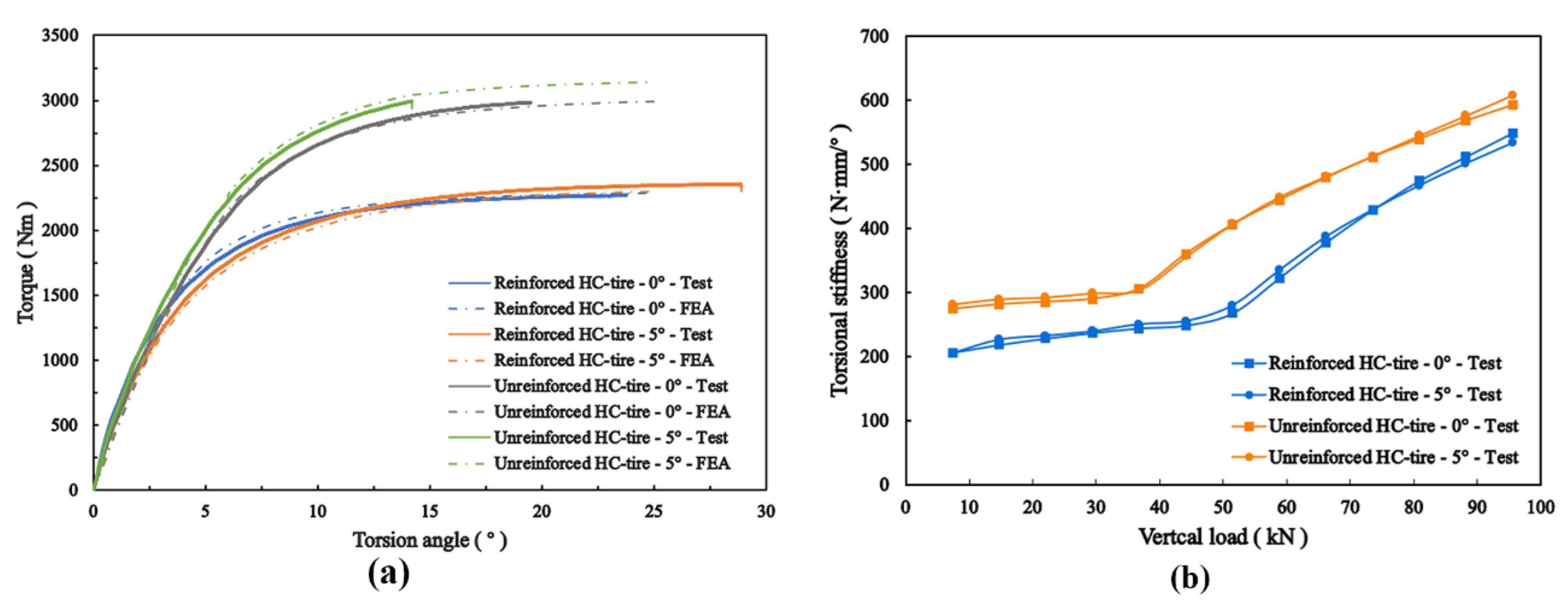
6.6. Torsional Stiffness

The measured and simulated torsion angles of the HC tire under varying torque conditions are shown in Figure 22a. The reinforced HC tire had a greater torsion angle under the same vertical load at the slip stage. At full slipping, the unreinforced HC tire produced greater torque, which was higher at the 5° than at the 0° test point, but the torque in the reinforced HC tire did not differ much between the two test points.
The variation in the measured torsional stiffness with vertical loads of the HC tire is shown in Figure 22b. It increased at the 0° and 5° test points with the vertical load, and the growth trend exhibited a gradual increase. The inflection point of the torsional stiffness of the reinforced HC tire was observed at a vertical load of 51.45 kN, whereas it was observed at 36.75 kN for the unreinforced HC tire, which indicates that the spiral steel ring can delay the occurrence of the inflection point.
Comparisons of the torsional stiffness fluctuation ratio of the 0° and 5° test points of the HC tire under different vertical loads are shown in Figure 23, which reveals that the spiral steel ring cannot reduce the fluctuation. Figure 23 also illustrates that when the vertical load was less than 51.45 kN, the torsional stiffness of the unreinforced HC tire increased by more than 21.31% compared to that of the reinforced HC tire under different vertical loads. When the vertical load was greater than 51.45 KN, the increase ratio gradually decreased. Therefore, the spiral steel ring can reduce the torsional stiffness, and when the vertical load is greater than 51.45 kN, the weakening effect decreases with the vertical load.

7. Conclusions

In this study, a high load capacity NPT was designed and fabricated, considering two tread designs: a built-in and non-built-in spiral steel ring. The static vertical, longitudinal, lateral, and torsional stiffness of the HC tire at 0° and 5° test points were studied based on experiments and simulations. From the analysis, the following key conclusions are drawn:
(1)
The accuracy of the FEM of the HC tire was verified from the static vertical stiffness test data. The FEM model can, therefore, be used to investigate the mechanical behaviors of the HC tire under varying working conditions;
(2)
The bearing mechanism of the HC tire is the bottom bearing, and the unit load of the unreinforced HC tire is 2.972 times and 1.615 times that of the solid and pneumatic tires, respectively;
(3)
Two inflection points are present in the vertical stiffness fitting line of the HC tire, which can provide a reference for the design of NPTs with variable vertical stiffness. The spiral steel ring embedded in the tread can reduce the vertical stiffness fluctuation and increase the vertical stiffness of the HC tire;
(4)
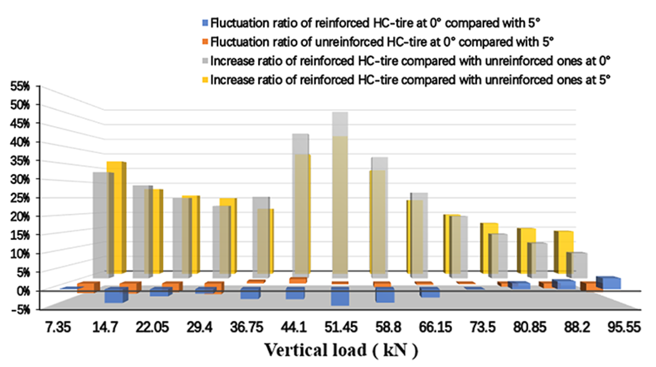
The longitudinal stiffness of the reinforced HC tire first decreases and then increases with the vertical load and reaches the minimum when the vertical load is 51.45 kN. In contrast, the longitudinal stiffness of the unreinforced HC tire decreases with the vertical load and tends to be stable when the vertical load is greater than 51.45 kN. The spiral steel ring embedded in the tread cannot reduce the longitudinal stiffness fluctuation but can increase the longitudinal stiffness of the HC tire;
(5)
The lateral stiffness of the HC tire first increases, decreases, and then increases with the increase in the vertical load. The spiral steel ring reverses the variation trend of the lateral stiffness with vertical loads at the 0° and 5° test points. However, the spiral steel ring embedded in the tread cannot reduce the lateral stiffness fluctuation;
(6)
The torsional stiffness of the HC tire increases with vertical load. The spiral steel ring embedded in the tread can reduce the torsional stiffness of the HC tire but cannot reduce the torsional stiffness fluctuation. The spiral steel ring embedded in the tread can reduce the torsional stiffness of the HC tire but cannot reduce its fluctuation;
(7)
The results of this study can guide the design of the support structure and reinforced tread structure of NPTs with high capacity requirements.

Author Contributions

Conceptualization, W.L. and S.L.; data curation, W.L.; formal analysis, W.L.; funding acquisition, W.L.; investigation, S.L.; methodology, W.L. and S.L.; project administration, W.L. and K.L.; resources, W.L.; software, S.L.; supervision, X.L., C.W., and K.L.; validation, S.L. and C.W.; visualization, S.L.; writing—original draft, S.L.; writing—review and editing, W.L. and Q.Z. All authors have read and agreed to the published version of the manuscript.

Funding

This research received no external funding.

Data Availability Statement

Data are available on request from the authors.

Acknowledgments

This research was partially supported by Liantian Trading (Shenzhen) Co., Ltd., and we express our heartfelt thanks.

Conflicts of Interest

The authors declare no conflict of interest.

References

  1. Zhuang, J.D. Automotive Tire Science; Beijing Institute of Technology Press: Beijing, China, 1995. [Google Scholar]
  2. Gent, A.N.; Walter, J.D. The Pneumatic Tire; National Highway Traffic Safety Administration: Washington, DC, USA, 2006.
  3. Rhyne, T.B.; Cron, S.M. Development of a non-pneumatic wheel. Tire Sci. Technol. 2006, 34, 150–169. [Google Scholar] [CrossRef]
  4. Bezgam, S. Design and Analysis of Alternating Spoke Pair Concepts for a Non-pneumatic Tire with Reduced Vibration at High Speed Rolling. Master’s Thesis, Clemson University, Clemson, SC, USA, 2009. [Google Scholar]
  5. Rutherford, W.L. Use of Orthogonal Arrays for Efficient Evaluation of Geometric Designs for Reducing Vibration of a Non-Pneumatic Wheel during High-Speed Rolling. Master’s Thesis, Clemson University, Clemson, SC, USA, 2009. [Google Scholar]
  6. Ju, J.; Summers, J.D.; Ziegert, J.; Fadel, G. Design of honeycomb meta-materials for high shear flexure. In Proceedings of the IDETC/CIE, San Diego, CA, USA, 8 August–2 September 2009. [Google Scholar]
  7. Ju, J.; Ananthasayanam, B.; Summers, J.D.; Joseph, P. Design of cellular shear bands of a non-pneumatic tire -investigation of contact pressure. SAE Int. J. Passeng. Cars Mech. Syst. 2010, 3, 598–606. [Google Scholar] [CrossRef]
  8. Narasimha, A.; Ziegert, J.; Thompson, L. Effects of material properties on static load-deflection and vibration of a non-pneumatic tire. SAE Int. J. Passeng. Cars Mech. Syst. 2011, 4, 59–72. [Google Scholar] [CrossRef]
  9. Narasimha, A. A Computational Method for Analysis of Material Properties of a Non-Pneumatic Tire and Their Effects on Static Load-Deflection, Vibration, and Energy Loss From Impact Rolling Over Obstacles. Master’s Thesis, Clemson University, Clemson, SC, USA, 2010. [Google Scholar]
  10. Ma, J.; Summers, J.D.; Joseph, P.F. Numerical simulation of tread effects on the interaction between cellular shear band based non-pneumatic tire and sand. In Proceedings of the IDETC/CIE, Washington, DC, USA, 28–31 August 2011. [Google Scholar]
  11. Rugsaj, R.; Suvanjumrat, C. Determination of material property for non-pneumatic tire spokes by inverse method. Key Eng. Mater. 2018, 777, 411–415. [Google Scholar] [CrossRef]
  12. Rugsaj, R.; Suvanjumrat, C. Finite element analysis of hyperelastic material model for non-pneumatic tire. Key Eng. Mater. 2018, 775, 554–559. [Google Scholar] [CrossRef]
  13. Rugsaj, R.; Suvanjumrat, C. Proper radial spokes of non-pneumatic tire for vertical load supporting by finite element analysis. Int. J. Automot. Technol. 2019, 20, 801–812. [Google Scholar] [CrossRef]
  14. Rugsaj, R.; Suvanjumrat, C. Development of a transient dynamic finite clement model for the drum testing of a non-pneumatic tire. In Proceedings of the TSME-ICoME, Pattaya, Thailand, 10–13 December 2019. [Google Scholar]
  15. Rugsaj, R.; Suvanjumrat, C. Dynamic finite element analysis of rolling non-pneumatic tire. Int. J. Automot. Technol. 2020, 22, 1011–1022. [Google Scholar] [CrossRef]
  16. Rugsaj, R.; Suvanjumrat, C. Study of mechanical properties of 3d printed material for non-pneumatic tire spoke. Key Eng. Mater. 2021, 880, 97–102. [Google Scholar] [CrossRef]
  17. Kim, K.; Ju, J.; Kim, D.M. Static contact behaviours of a non-pneumatic tire with hexagonal lattice spokes. SAE Int. J. Passeng. Cars Mech. Syst 2013, 6, 1518–1527. [Google Scholar] [CrossRef]
  18. Veeramurthy, M.; Ju, J.; Thompson, L.L.; Summers, J.D. Optimisation of geometry and material properties of a non-pneumatic tyre for reducing rolling resistance. Int. J. Vehicle Design 2014, 66, 193–216. [Google Scholar] [CrossRef]
  19. Meng, F.H.; Lu, D.F.; Yu, J.J. Flexible cellular structures of a non-pneumatic tire. In Proceedings of the IDETC/CIE, Charlotte, NC, USA, 21–24 August 2016. [Google Scholar]
  20. Zang, L.G.; Wang, X.Y.; Yan, P.W.; Zhao, Z.D. Structural design and characteristics of a non-pneumatic tire with honeycomb structure. Mech. Adv. Mater. Struct. 2021, 29, 4066–4073. [Google Scholar] [CrossRef]
  21. Jin, X.C.; Hou, C.; Fan, X.L.; Sun, Y.L.; Lv, J.N.; Lu, C.S. Investigation on the static and dynamic behaviors of non-pneumatic tires with honeycomb spokes. Compos. Struct. 2018, 187, 27–35. [Google Scholar] [CrossRef]
  22. Ganniari-Papageorgiou, E.; Chatzistergos, P.; Wang, X.X. The influence of the honeycomb design parameters on the mechanical behaviour of non-pneumatic tires. Int. J. Appl. Mech. 2020, 12, 2050024. [Google Scholar] [CrossRef]
  23. Ju, J.; Kim, D.M.; Kim, K. Flexible cellular solid spokes of a non-pneumatic tire. Compos. Struct. 2012, 94, 2285–2295. [Google Scholar] [CrossRef]
  24. Aboul-Yazid, A.M.; Emam, M.A.A.; Shaaban, S.; El-Nashar, M.A. Effect of spokes structures on characteristics performance of non-pneumatic tires. Int. J. Automot. Mech. Eng. 2015, 11, 2212–2223. [Google Scholar] [CrossRef]
  25. Wang, W.; Zhao, Y.Q.; Zang, L.G. Structure analysis and ride comfort of vehicle on new mechanical elastic tire. In Proceedings of the FISITA, Beijing, China, 27–30 November 2012. [Google Scholar]
  26. Du, X.B.; Zhao, Y.Q.; Wang, Q.; Fu, H.X. Numerical analysis of the dynamic interaction between a non-pneumatic mechanical elastic wheel and soil containing an obstacle. J. Automob. Eng. Proc IMechE Part D J Automob. Eng. 2016, 231, 731–742. [Google Scholar] [CrossRef]
  27. Zhao, Y.Q.; Xiao, Z.; Lin, F.; Zhu, M.M.; Deng, Y.J. Influence analysis of machining and installation errors on the radial stiffness of a non-pneumatic mechanical elastic wheel. Chin. J. Mech. Eng. 2018, 31, 68. [Google Scholar] [CrossRef]
  28. Wang, Q.; Zhao, Y.Q.; Du, X.B.; Zhu, M.M.; Fu, H.X. Equivalent stiffness and dynamics response of new mechanical elastic wheel. JVE Int. LTD J. Vibroeng. 2016, 18, 431–445. [Google Scholar]
  29. Wang, J.; Yang, B.; Lin, X.; Gao, L.; Liu, T.; Lu, Y.L.; Wang, R.G. Research of TPU Materials for 3D Printing Aiming at Non-Pneumatic Tires by FDM Method. Polymers 2020, 12, 2492. [Google Scholar] [CrossRef]
  30. Cezary, K.; Artur, Z.; Jan, P.; Anna AI, S.Z. Experimental and numerical testing of prototypical under ballast mats (UBMs) produced from deconstructed tires—The effect of mat thickness. Constr. Build. Mater. 2023, 369, 130559. [Google Scholar]
  31. Hulme, A.J.; Goodhead, T.C. Cost effective reprocessing of polyurethane by hot compression moulding. J. Mater. Process. Technol. 2003, 139, 322–326. [Google Scholar] [CrossRef]
  32. GB/T 228.1-2010; Metallic Materials-Tensile Testing-Part 1: Method of Test at Room Temperature. Standards Press of China: Beijing, China, 2010.
  33. HG/T 3849-2008; Ebonite-Determination of Tensile Strength and Elongation at Break. Standards Press of China: Beijing, China, 2008.
  34. GB/T 23663-2020; Test Method for Longitudinal and Lateral Stiffness of Motor Vehicle Tires. Standards Press of China: Beijing, China, 2020.
Figure 1. Structural explosion diagram of HC tire.
Lubricants 11 00180 g001
Figure 2. Design parameters of HC tire: (a) Geometric dimensions of HC tire and (b) thickness of metal parts.
Lubricants 11 00180 g002
Figure 3. Bending die and main structures of HC tire: (a) bending die; (b) similar ‘π’-shaped support substructure; (c) outer concave–convex substructure; and (d) inner concave–convex substructure.
Lubricants 11 00180 g003
Figure 4. Resistance spot welding.
Lubricants 11 00180 g004
Figure 5. Tread forming process: (a) mold positioning and temperature measurement; (b,c) tread pouring; and (d) tread demolding.
Lubricants 11 00180 g005
Figure 6. Material mechanics test: (a) metal tensile specimens; (b) uniaxial tensile test of metal tensile specimens; (c) polyurethane tensile specimens; and (d) uniaxial tensile test of polyurethane tensile specimens.
Lubricants 11 00180 g006
Figure 7. Stress–strain curves of polyurethane uniaxial tensile tests.
Lubricants 11 00180 g007
Figure 8. Static stiffness test of HC tire: (a) 0° test point; (b) 5° test point; (c) vertical stiffness test; (d) longitudinal stiffness test; (e) lateral stiffness test; and (f) torsional stiffness test.
Lubricants 11 00180 g008aLubricants 11 00180 g008b
Figure 9. Fitted Marlow constitutive curves of polyurethane.
Lubricants 11 00180 g009
Figure 10. FEM model of the HC tire.
Lubricants 11 00180 g010
Figure 11. Measured and simulated vertical displacement of the HC tire under varying vertical loads.
Lubricants 11 00180 g011
Figure 12. Absolute simulation errors in the vertical displacements of the HC tire.
Lubricants 11 00180 g012
Figure 13. Stress nephogram of the HC tire: (a) stress nephogram of reinforced HC tire at 0° test point; (b) stress nephogram of reinforced HC tire at 5° test point; (c) stress nephogram of unreinforced HC tire at 0° test point; and (d) stress nephogram of unreinforced HC tire at 5° test point.
Lubricants 11 00180 g013
Figure 14. Vertical stiffness simulation curves of the HC tire and its components: (a) vertical stiffness fitting lines of HC tire and (b) vertical stiffness curves of HC tire parts.
Lubricants 11 00180 g014
Figure 15. Contact state between support structure and outer concave–convex substructure.
Lubricants 11 00180 g015
Figure 16. Vertical stiffness data analysis of the HC tire.
Lubricants 11 00180 g016
Figure 17. Increased ratio of vertical stiffness of reinforced HC tire compared to unreinforced ones.
Lubricants 11 00180 g017
Figure 18. (a) Measured and simulated longitudinal displacement of the HC tire under different longitudinal load conditions and (b) measured longitudinal stiffness of the HC tire with varying vertical loads.
Lubricants 11 00180 g018
Figure 19. Longitudinal stiffness analysis of the HC tire.
Lubricants 11 00180 g019
Figure 20. (a) Measured and simulated lateral displacements of the HC tire under varying lateral loads and (b) measured lateral stiffness of the HC tire with varying vertical loads.
Lubricants 11 00180 g020
Figure 21. Lateral stiffness analysis of the HC tire.
Lubricants 11 00180 g021
Figure 22. (a) Measured and simulated torsion angles of the HC tire under varying torques and (b) measured torsional stiffness of the HC tire below varying vertical loads.
Lubricants 11 00180 g022
Figure 23. Torsional stiffness analysis of the HC tire.
Lubricants 11 00180 g023
Table 1. Mechanical property parameters of metal materials.
MaterialTensile Strength (MPa)Yield Strength (MPa)Young’s Modulus
(GPa)
Poisson Ratio
Si-Mn spring steel132612002070.28
Wheel steel6825362050.27
Disclaimer/Publisher’s Note: The statements, opinions and data contained in all publications are solely those of the individual author(s) and contributor(s) and not of MDPI and/or the editor(s). MDPI and/or the editor(s) disclaim responsibility for any injury to people or property resulting from any ideas, methods, instructions or products referred to in the content.

