Article

Effect of the Distribution Characteristics of TiC Phases Particles on the Strengthening in Nickel Matrix

School of Mechanical and Electronical Engineering, Lanzhou University of Technology, Lanzhou 730050, China
*
Author to whom correspondence should be addressed.
Lubricants 2023, 11(2), 83; https://doi.org/10.3390/lubricants11020083
Submission received: 17 January 2023 / Revised: 12 February 2023 / Accepted: 13 February 2023 / Published: 15 February 2023
(This article belongs to the Special Issue Friction and Wear on the Atomic Scale)

Abstract

:
Molecular dynamics (MD) was used to simulate the effect of TiC particles distribution on the tribological behavior of the reinforced composites. The mechanical properties, friction coefficient, number of wear atoms, stress and temperature, and microscopic deformation behavior of TiC/Ni composites during nano-friction were systematically investigated by MD to reveal the effect of TiC distribution on the friction removal mechanism of the material. It was found that the larger the radius of the TiC particles, or the shallower the depth of the TiC particles, the easier it was to generate stress concentrations around the TiC particles, forming a high dislocation density region and promoting the nucleation of dislocations. This leads to severe friction hardening, reducing the atomic number of abrasive chips and reducing the friction coefficient by approximately 6% for every 1 nm reduction in depth, thus improving the anti-wear capacity. However, when the radius of the TiC particles increases and the thickness from the surface deepens, the elastic recovery in material deformation is weakened. We also found that the presence of the TiC particles during the friction process changes the stress state inside the workpiece, putting the TiC particles and the surrounding nickel atoms into a high-temperature state and increasing the concentrated temperature by 30 K for every 1 nm increase in depth. Nevertheless, the workpiece atoms below the TiC particles invariably exist in a low-temperature state, which has a great insulation effect and improves the high-temperature performance of the material. The insight into the wear characteristics of TiC particles distribution provides the basis for a wide range of TiC/Ni applications.

1. Introduction

In recent years, academia has integrated reinforcements into the metal matrix to form composite materials that combine the advantages of the metal matrix and the reinforcements, improving the mechanical properties. These have become widely used structural materials in the aerospace and automotive sectors [1,2,3,4]. Among the numerous metal matrix composites, nickel-based titanium carbide composites have a higher strength and modulus combined with better fatigue resistance, wear resistance, and high-temperature properties [5]. However, the development of TiC/Ni composites is currently encountering two key critical challenges that influence their industrial application.
The first one is the difficulty of uniformly distributing the TiC reinforcement in the nickel matrix, particularly when TiC particles are added directly, which tends to break up the particles, reduce mobility, and give rise to uneven distribution. This leads to problems such as low strength and thermodynamic instability at the interface, reducing the strengthening effect [6,7,8]. Meanwhile, the particles can form agglomerates and cause extremely severe stress concentrations during the application, which can significantly reduce the performance of the material [9,10]. Another issue is that the mechanism for enhancement of the TiC relative to the nickel matrix during friction and the mechanism of interaction at the interface are unknown. Nevertheless, the interface plays an important role in the material properties, and the research on interfacial microstructure is the key to developing metal matrix composites [11,12,13,14,15]. Therefore, intensive research on reinforcement distribution and the two-phase interface microstructure will be important to the development of composite materials.
Presently, scientists are dedicated to the study of TiC and nickel-based alloys. Zhang et al. [16] found that the incorporation of TiC increased the yield strength of a nickel matrix composite at room and high temperatures. Han et al. [8] produced nickel matrix composites and found that the addition of TiC resulted in grain refinement, significant grain boundaries, a yield strength increase of 17%, and a significant strengthening mechanism for load-bearing and enhanced delocalization density. Yu et al. [17] synthesized Ni/TiC composites and found that TiC hindered crystal growth and that the Ni/40TiC composites had an average microhardness value of 851 HV and the lowest friction coefficient. Liu et al. [18] prepared Ni-Fe-based high-temperature alloys by adding trace amounts of TiC particles. Experimental results demonstrated that the presence of TiC particles increased elongation, ultimate tensile strength, and yield strength at room/high temperature. Domitner et al. [19] investigated the laser melting of WC particle-reinforced nickel-based composites. Their research revealed that the hardness depended on the crystal structure of the carbide, with particles composed as fine grains being much harder than those made up of coarse grains. Testa et al. [20] used a TiC suspension mixed with dry Tribaloy-400 for plasma spraying to obtain a composite coating. Experimental results revealed that a uniform oxide-based friction film formed at 700 °C.
However, the research at the interface between the nickel matrix and TiC is extremely complex, including the microstructure [21], defects [22], and atomic arrangement [23]. The frictional wear mechanism is indirectly derived from the results of experimental friction without observation of the dynamic migration and phase transition processes of the material [24]. Nonetheless, nano-friction is a process in which materials are continuously removed at the micron/nanometer scale [25], and molecular dynamics simulations can accurately observe the microscopic deformation behavior and microstructural evolution of materials during friction at the nanoscale. These simulations have been widely used in the study of metal composites and interfaces and can well compensate for the experimental shortcomings [26,27]. Meanwhile, MD also saves manpower and material resources, improves the efficiency of traditional experimental new material development, and promotes the rapid development of high-performance materials [28]. Xu et al. [29] applied MD to embed diamond-hard particles into the workpiece at different depths, revealing the mechanism of particle location on the removal from the substrate material. It was found that where the hard particles were at a sufficient depth, the cutting process was virtually unaffected by them. Fu et al. [30] studied the effect of the interface on trans-lamellar crack propagation in a TiAl alloy by MD. Their research revealed that with the improvement of the crack resistance of the layered interface, the corresponding dislocation density in the model also increased. Xu et al. [31] investigated the cavity collapse phenomenon in single crystal hcp-Ti with MD, and they found that the stress decreased with a reduction in the initial pore size, whereas the dislocation density grew with an increase in the initial pore size. Yin et al. [32] simulated and analyzed the effect that crystal orientation has on plastic deformation. It was found that the dislocation and layer dislocation evolution are two of the reasons for the anisotropy in the crystal.
In this work, a nickel-based titanium carbide composite with a unique nickel phase and TiC particles structure was constructed from a microscopic point of view, and nanofriction simulation was conducted. We analyzed the influence of the distribution of the reinforcement by TiC on the tribological behaviors of the substrate friction force, coefficient of friction, wear volume, stress and temperature, atomic displacement, etc., and elucidated the influence of the two-phase interface on the workpiece friction process.

2. Method

2.1. Simulation Modeling

The MD simulation model consisted of a TiC/Ni composite sample and a diamond grinding ball, as shown in Figure 1. Between them, the TiC/Ni composite sample consisted of two phases, the nickel matrix and the reinforcement TiC. Meanwhile, the model was divided into the base Model 1 and Model 2 with the same radius and variable depth, and variable radius and same depth according to the relative positions of the TiC particles in the XZ plane, and the TiC was treated as a uniformly distributed sphere [29,33]. The distance between two adjacent TiC particles was maintained at 50 Å, and the equal radius and depth were uniformly distributed in the nickel matrix. Based on the same radius and variable depth, three models were created for the same radius of 25 Å and different depths of 20, 30, and 40 Å, respectively, as illustrated in Figure 1, Model 1. Similarly, based on the variable radius and same depth, three models were created for the same depth of 20 Å and different radii of 15, 20, and 25 Å, respectively, as illustrated in Figure 1, Model 2. The MD simulation included two phases: the relaxation and friction phases. With the workpiece fully relaxed, it existed in its natural real state. The grinding ball then created a linear friction along the [−1 0 0] direction with a speed of 10−3 Å/fs, friction distance of 36 nm, and friction depth of 10 Å. Based on the model created, the effects of the distribution on the tribological behavior of nickel substrates from nanoscale TiC reinforcements were systematically investigated by controlling a single variable.
In the simulation, the workpiece was divided into the boundary, thermostat, and Newtonian layers from the bottom up, according to the various functions of the atoms during the friction process when the boundary layer was not involved in atomic motion and prevented the workpiece from moving rigidly [34]. The thermostat layer ensured that the temperature remained at room temperature, and the atoms followed Nosé–Hoover thermodynamics to simulate the heat dissipation [35]. The Newtonian layer was the focal region for studying the deformation of the workpiece, following Newton’s second law, and the velocity Verlet algorithm was used for numerical integration [36]. Simultaneously, to reduce the influence of dimensional effects, periodic boundaries were used in the Y-direction and free boundaries in the X- and Z-directions [37,38]. In addition, the simulation temperature was 300 K. The NVE system ensured that the energy and volume of the system and the atomic number were constant [39]. The detailed MD parameters are shown in Table 1.

2.2. Determination of Potential Function

The studies in this paper used the MEAM, EAM, Morse, and Tersoff potentials. Among them, the MEAM potential was employed to simulate the forces between TiC atoms, and the total energy E is [40,41]
E = i F i ( ρ i ) + 1 2 i j S i j i j ( r i j )
where Fi is the embedding energy for atom i embedded in a background electron density ρi, Sij is the screening function, i j ( r i j ) is the pair interaction between atoms i and j, and rij is the distance between atoms i and j. More details on the parameters can be obtained from references [40,42].
The extensively employed EAM potential [38,43,44] and Tersoff potential [45] describe the forces between the matrix nickel atom (Ni-Ni) and the diamond-grinding sphere (C-C), respectively. The Morse potential was adopted to describe the forces between metallic Ni and diamond-grinding sphere C, as shown in Equation (2) [46]:
U M orse ( r i j ) = D [ e 2 α ( r i j r 0 ) 2 e α ( r i j r 0 ) ]
where D is the cohesive energy, r0 and rij are the equilibrium distance and separation distance between atoms i and j, respectively, and α is the bulk modulus fitted to the material. The parameters for the Morse potential were D = 0.1eV, α = 2.2 Å−1, r 0 =2.4 Å, according to ref. [47].

3. Results and Discussion

3.1. Friction Performance Analysis of Workpieces with Different Depths

Based on Model 1 in Figure 1, the effect of the depth distribution of the reinforcing phase TiC on the tribological behavior of the composite was investigated. Figure 2 shows the force–displacement curve during the friction process. The transverse force (Y-direction) is not shown because the forces on both sides of the grinding groove on the grinding ball were balanced, so that the average value during friction was zero. The normal force (Fn) and frictional force (Ff) increased rapidly at the beginning of friction and then gradually stabilized, fluctuating above and below the equilibrium position, and the amplitude of the Ff fluctuation gradually increased with the decrease in the depth. The reason for the fluctuation was mainly related to the release of collected energy that occurs in the formation of dislocations, resulting in a decrease in Ff and Fn that leads to fluctuations. It can be inferred that the shallower the depth, the more complex the deformation inside the workpiece. It was also found that the Ff during friction produced differences at different depths, while the Fn was essentially the same, indicating that the depth of the TiC particles had an influence on the friction process of the nickel matrix.
To investigate the influences of the TiC particles depth on the friction coefficient of the workpiece and to eliminate the errors caused by the large fluctuations in the early friction period, Ff and Fn were averaged after 16 nm of friction, and the Coulomb friction model was used to determine the friction coefficient [48].
μ = Ff/Fn
As shown in Figure 3, one can see that Ff increased continuously with the increase in the depth while Fn remained basically constant. Therefore, Ff was primarily responsible for the variance in the friction coefficient. When the depth increased by 1 nm, the friction coefficient increased by about 6%. This is mainly because the shallower the depth of the TiC particles, the more force is absorbed by the TiC particles, resulting in a smaller Ff, and as a result, when the depth lowers, the friction coefficient does as well.
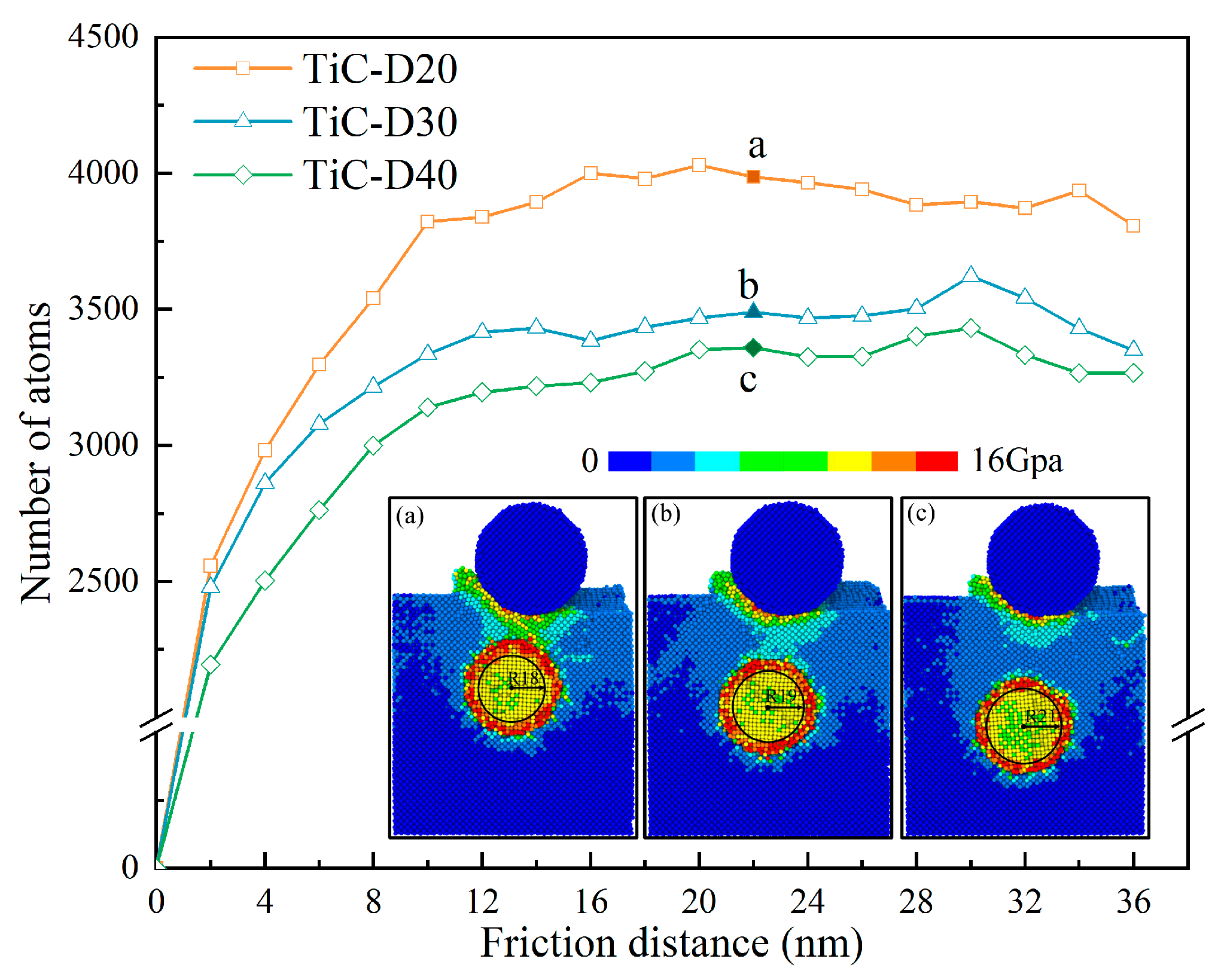
Figure 4 shows the von Mises stress distribution and the number of atoms with stresses greater than 14 Gpa during the friction process. The von Mises stress distribution is computed according to Equation (4):
σ M = 1 2 [ ( σ x x σ y y ) 2 + ( σ x x σ z z ) 2 + ( σ y y σ z z ) 2 ] + 3 ( σ x y 2 + σ x z 2 + σ y z 2 )
where σij is the virial stress component of each atom.
The local stress concentration between the grinding ball and the TiC particles rapidly decreased when the depth increased, and the atoms gradually became predominantly green to light blue, as shown in Figure 4a–c. Meanwhile, the high-stress region was mainly concentrated around the TiC ball; the number of TiC balls not turned into high-stress atoms gradually expanded as the depth of the thickened TiC particles increased, and the diameter gradually changed from 18 to 21 nm. In addition, it was also found that the number of high-stress atoms greater than 14 Gpa gradually increased with the increase in the friction distance, while the number of high-stress atoms was basically constant when the friction distance exceeded 12 nm. This was attributed to the fact that the grinding ball thereafter always acted near the TiC particles, and the stress in the rear region after friction gradually relaxed and was again locally concentrated between the TiC particles and grinding ball, putting the process in dynamic equilibrium and leading to a basically constant number of high-stress atoms. This demonstrated that local stress concentration was easily generated around the TiC particles, and local stress at the interface increased as the depth became shallower.
This study found that the presence of the TiC particles at different depths had different effects on the dislocation movements, as shown in Figure 5, using DXA analysis provided by the OVITO software to determine the dislocation types and cutoff position during the friction process. As shown in Figure 5(a1)–(a3), to release the plastic deformation around the grinding ball, many dislocations were generated inside the workpiece, and as seen in Figure 4, energy existed at the interface, and local stress concentrations were generated around the TiC particles. These, in turn, promoted the dislocation nucleation. However, the development of the dislocations cutoff at the TiC particles surface and the presence of a high-stress zone surrounding the TiC particles led to an inability to deliver the activation energy required for cross-slip, making it difficult for dislocations to cross the obstacle [49].
Meanwhile, as the depth decreased, the number of dislocations inside the workpiece gradually increased and accumulated on the TiC particles surface. As mentioned before, the more concentrated the local stress, the more easily dislocations are generated. In addition, it was also found that when the friction distance was 23 nm, elastic recovery occurred in the entire workpiece after friction, and the depth was directly proportional to the elastic recovery, as shown by 1 in Figure 5. When there was 33 nm of friction distance, the elastic recovery of the workpiece with a depth of 20 nm at TiC3 did not change significantly, as shown by 2 in Figure 5(c1). However, the workpieces with a depth of 40 nm all underwent a large elastic recovery after friction, and the dislocations basically disappeared, as shown by 3 in Figure 5(c3). The shallower the depth, the more concentrated the local stress, the more easily dislocations were generated, and the weaker the elastic recovery ability.
Figure 6 shows the total dislocation lengths. We observed that the shallower the depth, the longer the total length of dislocation during the entire friction process, and the fluctuation gradually reduced as the depth increased. This was because the introduction of the reinforced TiC particles had a van der Waals force and the presence of the two-phase interface made it easy for dislocations to pile up at the interface during the slip process [50]. Dislocation buildup was more likely to occur in workpieces with shallow depths during the friction process, leading to an increase in dislocation length with decreasing depth. However, as the depth increased, the dislocation formation decreased and the damage was weakened, leading to a gradual weakening of the fluctuations. Combined with the results in Figure 5, this further indicated that the shallower the depth, the easier a network of dislocation can be formed, thus improving the resistance of the workpiece to wear. In addition, the accumulation of dislocations can lead to unstable plasticity and thus reduce the ductility of the workpiece [4].
Figure 7 depicts the statistics of the quantity of dislocations that occurred when the grinding ball was immediately above the TiC particles. One can see that the number of dislocations increased as the friction distance increased. However, when the friction distance was the same, the number of dislocations was reduced with increasing depth. This indicated that the closer the TiC particles was to the workpiece surface, the higher the number of dislocations, and the dislocation density in the region increased, leading to the strengthening of the region, known as dislocation strengthening. Combined with the findings in Figure 5, the closer the TiC particles were to the workpiece surface, the more easily the dislocation entanglement was formed, leading to the occurrence of friction hardening.
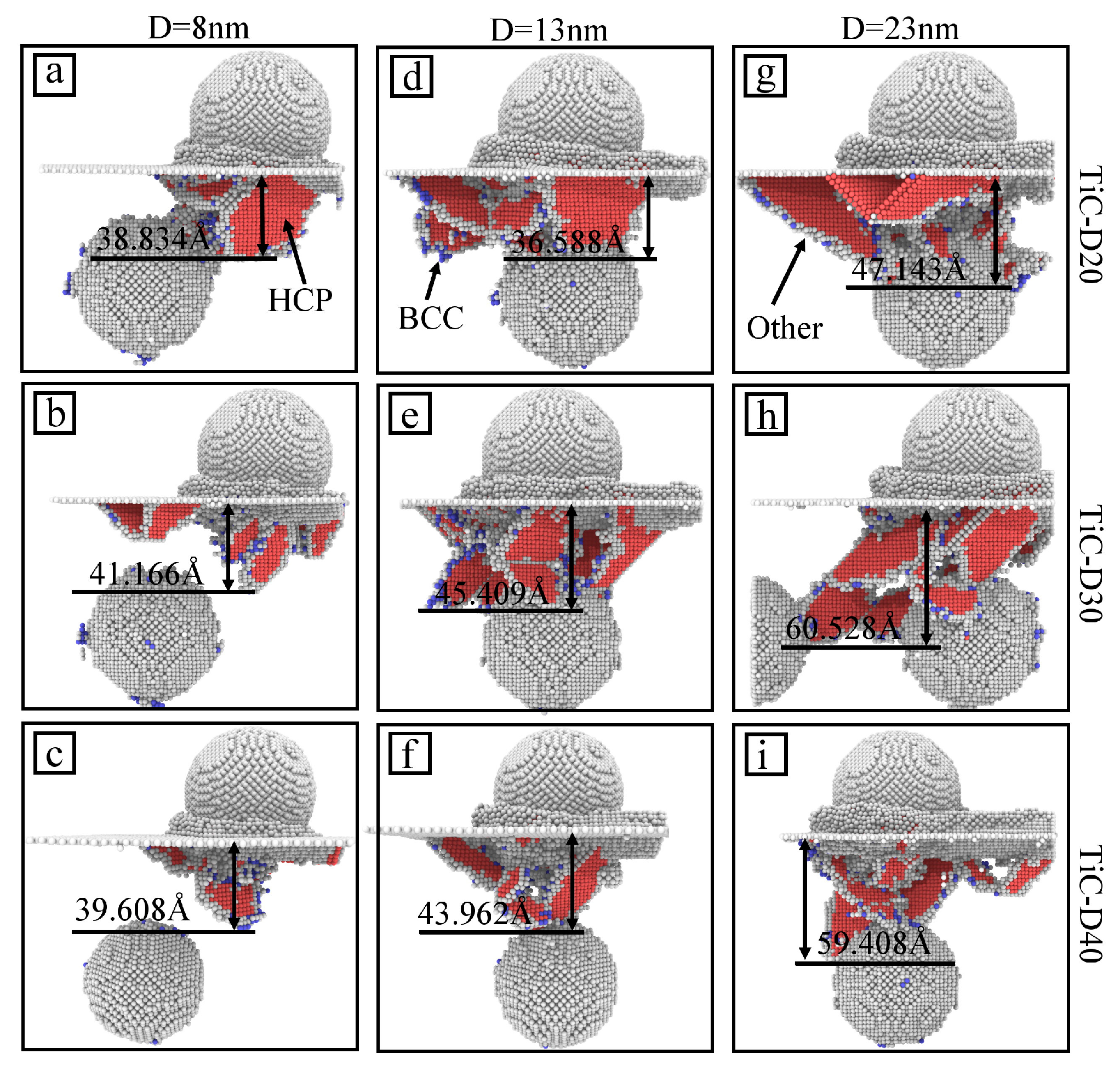
Figure 8 shows a schematic representation of the defects at different TiC particles depths and friction distances. The different types of atoms were colored using the CNA (Common Neighbor Analysis) method. As shown in Figure 8a–c, the defect depths at different TiC particles depths were basically the same at the beginning of the friction, and the defects inside the workpiece with the depth of 20 Å touched the TiC particles’ surface. When the grinding ball was immediately above the TiC particles, the defect depth increased as the depth of the TiC particles increased, as shown in Figure 8d,e. However, the defect depth did not change significantly after a depth of 30 Å, as shown in Figure 8e,f. The same result was produced where the grinding ball was immediately above the next TiC particles, as shown in Figure 8g–i. The above results demonstrated that at the same friction depth and friction distance, the shallower the depth, the shallower the internal damage depth of the workpiece, and the stronger the internal protection ability of the workpiece.
This indicated that the usual phase transformation of the nickel-based single crystal with FCC structure became an HCP structure. Therefore, the HCP structure atoms effectively responded to the characteristics of workpiece deformation. The variation in the number of atoms in the HCP structure is shown in Figure 9. One can see that no large differences in the number of HCP structure atoms appeared at the initial friction. Nevertheless, as the friction distance increased, the number of HCP structure atoms decreased with increasing depth and was accompanied by large fluctuations. Figure 9a,b,d,e,g,h correspond to Figure 8, and we found that the deeper the defect depth, the lower the number of HCP defect atoms generated inside the workpiece. This indicated that the shallower the depth of the workpiece, the more easily the workpiece will produce defects, and under extrusion it was easy to produce fine defects, causing dislocation entanglement and atomic clustering phenomena to appear and resulting in difficult deformation and removal of the workpiece material.

3.2. The Effect of Different Depths on Atomic Motion and Temperature

Defects such as vacancies and interstitial atoms can destroy a perfect crystal structure. When a perfect crystal structure is disrupted, the atoms in its intrinsic lattice sites are shifted, which is the main reason for the formation of defects such as vacancies and interstitial atoms [51]. Calculation of vacancy/interstitial atoms was conducted by Voronoi cell analysis in OVITO [52], as shown in Figure 10. It can be seen that the vacancy/interstitial atoms at the initial friction were growing rapidly and at the same rate at different depths. However, the number of vacancy/interstitial atoms increased as the friction distance increased, and the shallower the depth, the higher the growth speed of the number of vacancy/interstitial atoms, as shown by the dashed line in Figure 10. When defects such as vacancies appeared in the friction process, they interacted with the dislocations in the process of slipping; this led to the appearance of dislocation pinning, which hindered the free sliding of the dislocations and made it difficult for the dislocations to slip, resulting in friction hardening [53]. The above results demonstrated that as the TiC particles depth decreased, the number of vacancy/interstitial atoms gradually increased and the slip resistance of dislocations gradually increased, leading to the increasing strength of TiC/Ni composites.
Figure 11 shows the color calibration of the wear morphology based on the depth of the atomic Z-direction, investigating the wear depth for different TiC particles depths. a, b, and c represent friction distances of 13, 23, and 33 nm, respectively, and (a1), (a2), and (a3) represent depths of 20, 30, and 40 Å, respectively. By comparing (a1), (a2), and (a3) in Figure 11, we found that the abrasion depth after rubbing was less than the predetermined abrasion depth of 10 Å. The abrasion depth after rubbing decreased gradually with the increases in TiC particles depths, which were 8.781, 6.704, and 6.528 Å, respectively. As previously described, the shallower the depth, the stronger the action energy absorbed by the TiC particles, making it more difficult for the workpiece with shallower depth to experience elastic recovery. Similarly, when the rubbing distances were 23 and 33 nm, the same rules as for 13 nm existed for the abrasion depth, which decreased with the increasing of TiC particles depth, as shown in (b1), (b2), (b3) and (c1), (c2), (c3) in Figure 11.
To illustrate the impact of the TiC particles depth on the post-friction abrasion depth, the elastic recovery rate was calculated for different depths based on the values of the predetermined abrasion depth of 10 Å and the post-friction abrasion depth, as shown in Equation (5):
ε = d 0 d d 0 × 100 %
where ε is the elastic recovery rate, and d0 and d are the predetermined values of the abrasion depth, and the abrasion depth, respectively. The results are shown in Table 2.
When the friction distance was 13 nm, the elastic recovery gradually increased with the increases in TiC particles depth, which were 8.127%, 21.973%, and 23.147%. Meanwhile, the difference in elastic recovery rate was greater for depths of 20 and 30 Å. However, the difference in elastic recovery rate was smaller for depths of 30 and 40 Å. This indicated that the influence of TiC relative to the matrix gradually disappeared after a depth of 30 Å. In addition, where the friction distance was 33 nm, the close proximity of the grinding ball to the friction termination position made the elastic recovery rates all relatively small. It was noticeable that the depth of 20 Å basically did not cause elastic recovery. It was further demonstrated that the TiC particles reduced the ductility of metal while absorbing some of the force exerted by the grinding ball on the workpiece.
A typical atomic displacement vector diagram of the workpiece when the grinding ball was pressed positively on the TiC particles was obtained in order to clearly observe the deformation behavior of the workpiece at various TiC particles depths, as shown in Figure 12. When the TiC particles depth was 20 Å, most of the nickel atoms produced a 45° displacement trend along the easiest slip plane of the FCC, as shown by 1 in Figure 12a. However, the presence of TiC as a hard phase made it impossible for the atoms to break through the barrier and move in the previous direction, leading to a small displacement shift of the nickel atoms close to the TiC particles, as shown by 2 in Figure 12a. With increasing depth, more atoms were displaced along the 45° direction, as shown by 1 in Figure 12b. Nickel atoms close to the TiC particles underwent a larger displacement deflection, and the area where the deflection occurred also increased, as shown in Figure 12b 2 and D2. However, as the depth continued to increase (TiC particles depth of 40 Å), all the nickel atoms above the TiC particles were deflected, and the deflected region continued to increase, as shown in Figure 12c 1 and D3. This was because the difference in hardness between the two materials, TiC and the grinding ball, was small, and the influence between the atoms of TiC and the grinding ball weakened as the depth increased, which caused the action energy absorbed by the TiC particles to weaken continuously. Meanwhile, the obstruction of TiC relative to the movement of nickel atoms was weakened, and the Ni atoms traveled in the weaker direction of the workpiece, so the range of movement of nickel atoms expanded, leading to an increase in the deformation of the workpiece.
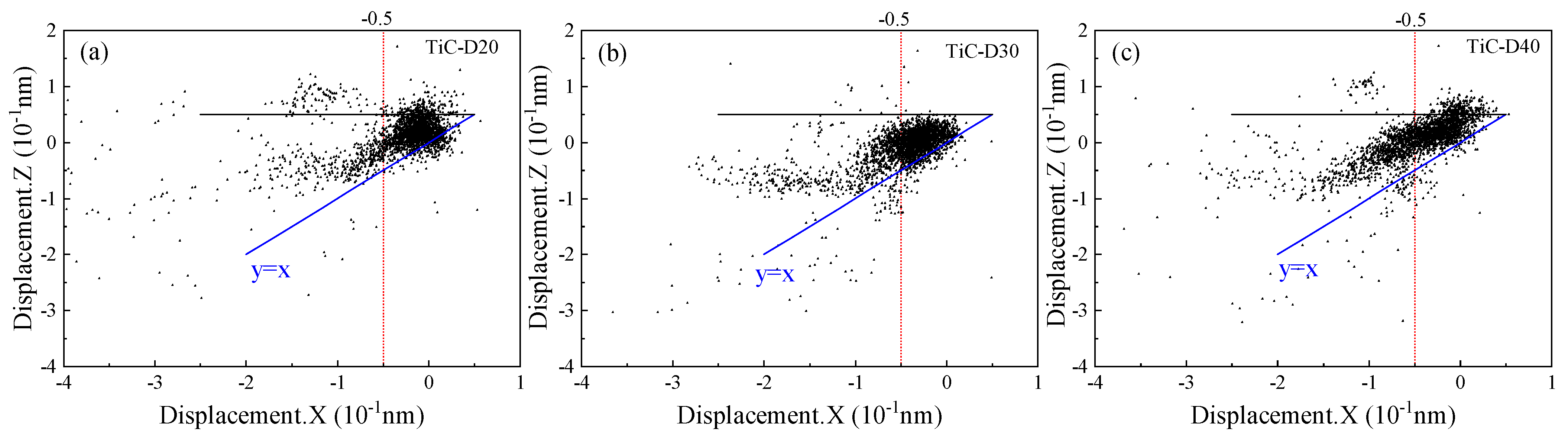
To distinguish the degree of deformation of the nickel matrix at different depths during the friction process, a displacement scatter plot was drawn on the basis of the displacement components in the X- and Z-axis directions for each atom at a friction distance of 23 nm, as shown in Figure 13. As shown in Figure 13a, the atomic displacement in the X-direction is negative, indicating that the direction of atomic motion coincided with the friction direction. Meanwhile, the atoms of the FCC structure with plastic deformation should be concentrated in the direction of 45° in the XZ plane. However, the existence of the TiC particles makes some of the atomic Z-direction displacements smaller than the X-direction displacements, indicating that the TiC particles changed the characteristics of the atomic plastic deformation of the FCC structure and made the workpiece less susceptible to deformation in the Z-direction. The appearance of atomic displacements larger than 0 in the X- and Z-directions indicated that the workpiece underwent elastic recovery. It is worth noting that the X-direction displacements are mainly concentrated in [−0.5, 0]. However, with increasing depth, the number of atoms with X < −0.5 Å gradually increases, and the atomic displacements in the Z-direction remain smaller than the X-direction displacements, with a gradual increase in atoms deviating from the 45° direction, as shown in Figure 13b,c. This indicated that the atomic motion was mainly dominated by transverse deformation, and the deformation of the workpiece increased with the increase in the depth. It can be inferred that TiC had a significant effect on the deformation of the workpiece in the Z-direction.
Since it is not possible to calculate the atomic volume, the number of wear atoms is often used instead of the wear volume in MD [54,55]. Atoms displaced by more than 3.524 Å in the amorphous structure of the matrix are wear atoms [56]. Figure 14 shows the variation of wear atoms with friction distance for different depths. When the friction distance was less than 8 nm, the wear atoms at different depths exhibited no differences. This suggested that the TiC particles had no effect on the workpiece and that the grinding ball only affected pure nickel at this stage. However, with the increase in the friction distance, the number of wear atoms continuously increased with the increase in the depth. It is noteworthy that the number of wear atoms near the region of TiC was smaller than that of the nickel matrix, as depicted by the black line in Figure 14. Therefore, we can infer that the presence of the TiC particles made the material less susceptible to removal and reduced wear.
As previously described, the TiC particles changed the movement of the workpiece atoms, so the microstructural changes could be studied by the displacement of the TiC particles atoms. The variation in the number of atoms with TiC particles atomic displacements greater than 2.5 Å at various depths is depicted in Figure 15. It can be clearly seen that the number of displaced atoms produced during the friction process increased continuously, and the number of displaced atoms decreased gradually with increasing depth for the same friction distance. This was primarily because as the depth increased, the number of displacements produced decreased as the impact of the grinding ball on the TiC particles, the impact of defects on the TiC particles, and the contact between the atoms of the two phases all lessened. Additionally, the left hemisphere of the TiC particles always contained more displaced atoms than the right hemisphere because of the left-to-right friction mode at all times, as shown by a, b, and c in Figure 15.
Figure 16 shows the atomic potential energy distribution when the grinding ball was immediately above the TiC particles at different depths. R25 is represented internally as TiC and R25-R40 as nickel atoms. Numerous green atoms with low potential energy are found in the TiC particles, while numerous yellow atoms with high potential energy are found in the nickel phase, as depicted. The change in the potential energy of the atoms was mainly related to the change in the lattice structure, and the nucleation, development, and extension of dislocations caused a change in the potential energy of the atoms. As the atoms were squeezed by the joint action of the grinding ball, the lattice was deformed by the pressure and the accumulated strain energy increased. When the strain energy increased to a certain value, the atomic lattice rearranged itself, generating dislocations and releasing the strain energy to be converted into atomic potential energy. As previously described, the shallower the depth, the higher the number of dislocations, and the strain energy was converted into atomic potential energy during dislocation generation, resulting in a gradual increase in the potential energy of nickel atoms as depth decreased, as shown in Figure 16a. In addition, the smaller atomic spacing between the TiC particles and the surrounding nickel atoms under extrusion generated the interatomic repulsion, leading to the generation of high-potential-energy nickel atoms around the TiC particles.
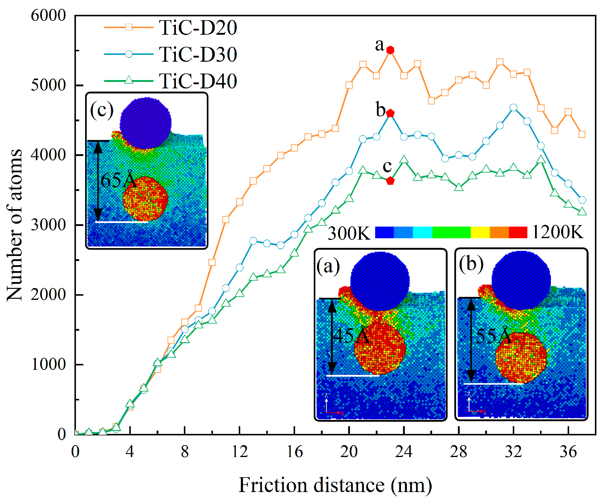
Figure 17 shows the temperature distribution of the workpiece for different TiC particles depths, and the number of high-temperature atoms at 700–1200 K. The number of high-temperature atoms increased rapidly with increasing friction distance and then stabilized, and the number of high-temperature atoms at a depth of 20 Å was always higher than at other depths, as shown in the curve in Figure 17. This was because the more intense the movement of the nickel atoms under their mutual extrusion as the grinding ball approached the TiC particles, the higher the energy of the atoms acting on the TiC particles, causing the TiC particles atoms, as well as the nickel atoms between the grinding ball and the TiC particles, to be at a high temperature, as shown in Figure 17a. The increase in depth led to a weakening of the atomic motion between the grinding balls and the TiC and to a decrease in the energy acting on the TiC particles, which, in turn, led to a decrease in the number of atoms at high temperatures. However, the atoms of the TiC particles were still in a higher-temperature state, as shown in Figure 17b,c. This indicated that the TiC particles absorbed part of the energy acting on the workpiece by the grinding ball. Meanwhile, comparing Figure 17a–c, it can be seen that the TiC particles was always higher than the temperature of the nickel atoms at the same height, while the temperature of the nickel atoms below the TiC particles was basically the same. In addition, the nickel atoms in the high-temperature region expanded with increasing depth, from 45 to 65 Å. This suggested that TiC had a positive effect on improving the high-temperature properties of the workpiece.
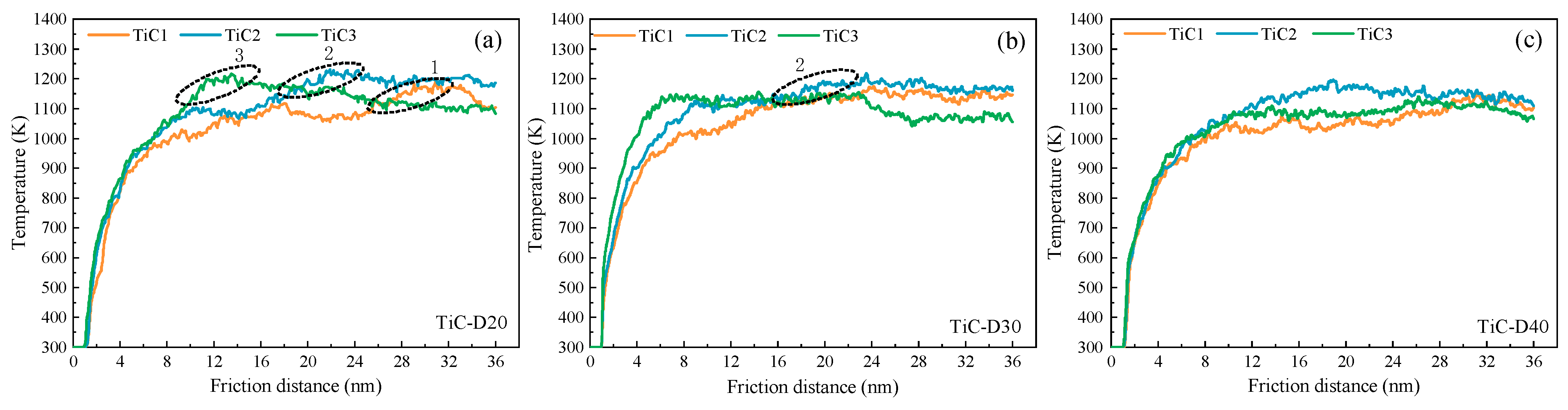
Figure 18 shows the variation curve of the TiC ball temperature with friction distance for different depths. The grinding ball rubbed the TiC balls from TiC3 to TiC1 balls. As shown in Figure 18a, the temperature of the TiC3 ball with a depth of 20 Å increased continuously with the increase in the friction distance. When the grinding ball was directly above the TiC3, the temperature reached an extreme value (1200 K), as shown by 3 in Figure 18a. The TiC particles, as previously mentioned, prevented the development and expansion of defects and the movement of nickel atoms, leading to a constant increase in temperature and eventually to an extreme value. However, when the frictional effect of the grinding ball on the TiC particles diminished (away from the TiC particles), the atoms underwent elastic recovery, leading to a gradual decrease in temperature. Similarly, the same variation rule existed when the grinding ball acted on the other TiC particles, as shown by 1 and 2 in Figure 18a. However, as the depth increased, the interaction between the atoms of the two phases gradually decreased, leading to a decrease in the temperature of the TiC balls with increasing depth, as shown in Figure 18b,c. Combined with Figure 17a–c, this further demonstrated that the high-temperature atoms were primarily TiC particles atoms.
As mentioned before, the high-temperature region of nickel atoms expanded with increasing depth. To further analyze the nickel atom temperature variation, the number of atoms with nickel atom temperatures in the range of 300–700 K was counted, as shown in Figure 19. When the friction distance was 13 nm, the nickel atoms were mainly concentrated at 360 K, and the number decreased gradually with the increase in the depth. However, after the temperature exceeded 400 K, the number of nickel atoms with a depth of 40 Å was always higher than the number of its depth, as shown in Figure 19a. The overall temperature of nickel atoms increased continuously with increasing friction distance, and the temperatures at 23 and 33 nm were concentrated at 390 and 420 K. Similarly, the number of nickel atoms at 390 and 420 K decreased gradually with increasing depth. However, after the temperature exceeded 430 and 460 K, respectively, the number of nickel atoms increased with increasing depth and the discrepancy constantly increased, as shown in Figure 19b–c. Combined with (a), (b) and (c), it was further demonstrated that the presence of the TiC particles had a certain heat insulation effect, and the heat insulation effect was gradually weakened as the depth increased and the high-temperature region was expanded.

3.3. Influence of TiC Particles Radii on Tribological Properties of Nickel Substrates

Considering the effect of TiC depth distribution on TiC/Ni composites, based on Model 2 in Figure 1, the effect of TiC particles radius distribution on the tribological behavior of the nickel matrix was investigated. 
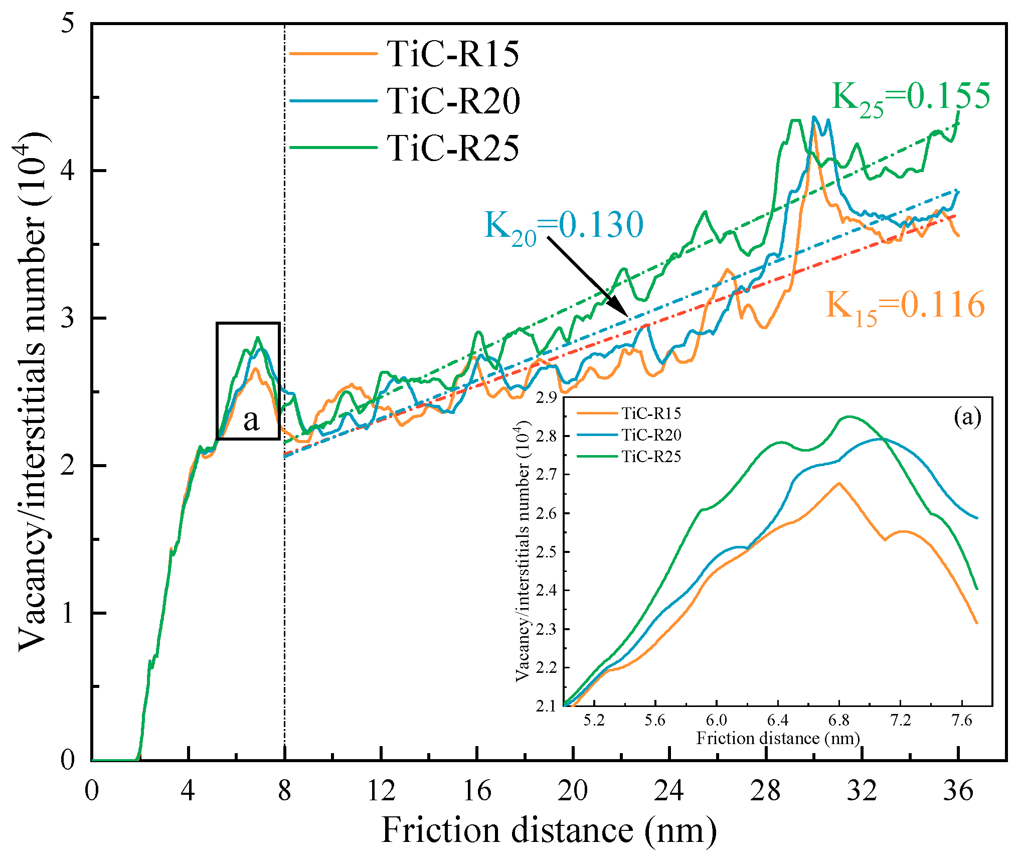
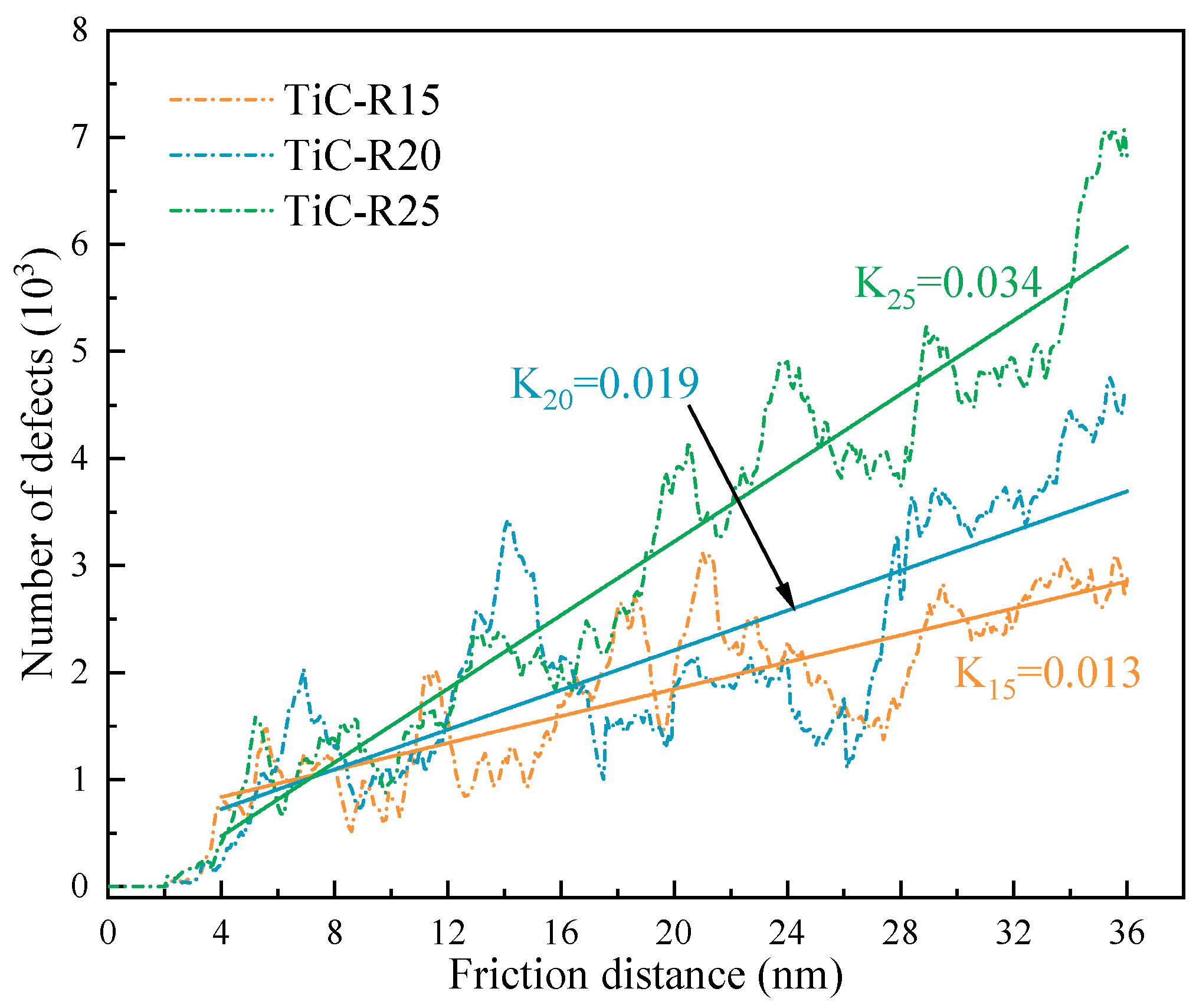
Figure 20 shows the variation curves of the number of vacancy/interstitial atoms for different TiC particles radii. One can see that the number of vacancy/interstitial atoms is the same for TiC particles workpieces with different radii at the initial friction. Nevertheless, at a friction distance close to 8 nm, as the TiC particles centers are all located at the same position, at the same friction distance, the relative distance between the grinding ball and TiC particles decreases with increasing radius, leading to an increase in the number of vacancy/interstitial atoms produced with increasing radius, as shown in Figure 20a. Meanwhile, a linear fit was performed for the number of vacancy/interstitial atoms after 8 nm, as shown by the dashed line in Figure 20. It was found that the slope of the vacancy/gap atom number gradually increases with increasing radius; the slope increases from 0.116 to 0.155, and the number of vacancy/interstitial atoms increases with increasing friction distance. This suggested that the introduction of the TiC particles caused the formation of vacancy/interstitial atoms inside the workpiece, and it was easier to generate vacancy/interstitial atoms as the radius increased, making dislocation slip difficult and leading to more obvious friction hardening.
Based on the famous Bailey–Hirsch law [57], as shown in Equation (6):
τ = G α b ρ + τ 0
where α is the correction factor of the material, b is the Burgers vector, G is the shear modulus, ρ is the dislocation density, τ is the shear flow stress, and τ 0 is the intrinsic flow strength of the low dislocation density material.
Equation (6) shows that the dislocation density ρ is the determining factor for the shear flow stress τ . The greater the dislocation density, the greater the ability to resist plastic deformation. The dislocation density is calculated as shown in Equation (7):
ρ = l/V
where l and V are the total length of the dislocation and the volume of the cut area, respectively.
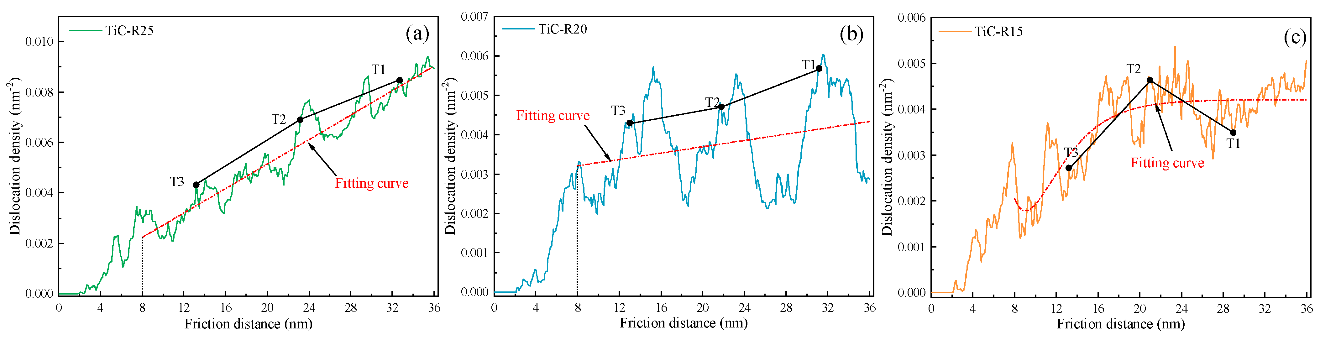
The dislocation was extracted by DXA, and the dislocation density variation curve with friction distance was calculated by Equation (7), as shown in Figure 21. Meanwhile, to observe the variation of the dislocation density with the friction distance more intuitively, the dislocation density curves were fitted (as red lines), as shown in Figure 21a–c.
It can be seen that the fitted curve gradually decreases in slope as the radius of the TiC particles decreases. Meanwhile, the dislocation density grew with increasing friction distance, which caused interactions between dislocations, leading to the appearance of dislocation entanglement and the formation of barriers to dislocation movement, thus improving the strength of the workpiece [58]. It was noteworthy that the dislocation density in the nearby region of the TiC particles was significantly higher than the dislocation density at other locations, as shown by T1, T2, and T3 in Figure 21a,b. It can be inferred that the TiC particles with large radii tended to form a high dislocation density region, leading to an increase in the material’s deformation resistance and an increase in the friction hardening rate of the workpiece, making it difficult for plastic deformation to occur. However, when the radius of the TiC particles was reduced to a certain value, the presence of the TiC particles did not have a large effect on the dislocation density, as shown in Figure 21c T1, T2, and T3. In addition, the dislocation density continuously fluctuated throughout the process because of the workpiece’s elastic-plastic deformation.
Figure 22 shows the average friction coefficient, friction, and normal force at different TiC particles radii. After the grinding ball was positioned at 8 nm, the average values were obtained, and the friction coefficient was determined by the Coulomb friction model. The normal force grew as the TiC particles radii increased, and the friction force decreased with this parameter. Therefore, the friction coefficient decreased as the radius of the TiC particles increased. As previously described, the large-radius TiC particles tended to cause a high dislocation density zone, which improved the strength of the workpiece, creating the increasing trend of opposite frictional and normal forces, resulting in the friction coefficient reducing as the radius increased.
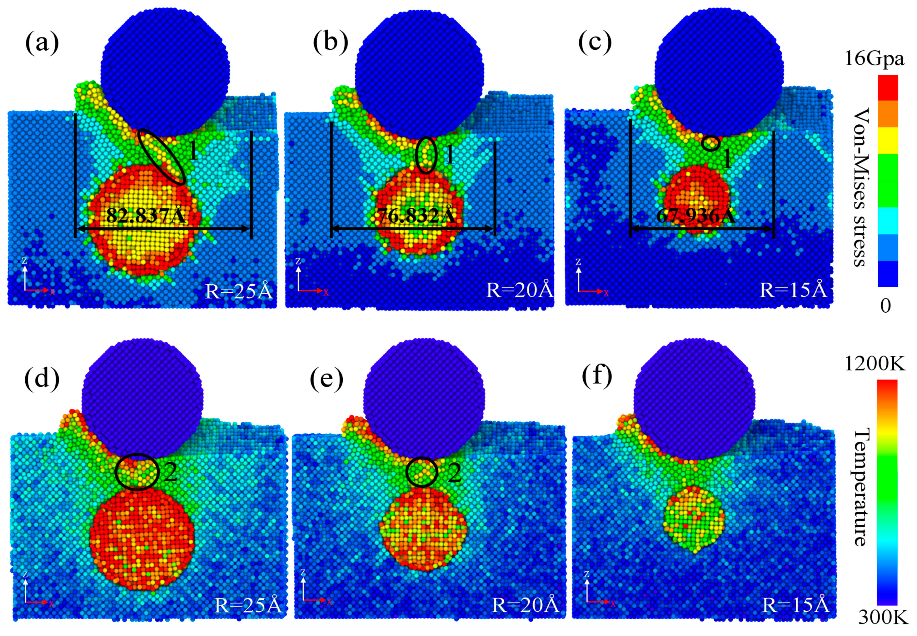
Figure 23 shows the von Mises and temperature clouds for different TiC particles under positive pressure of the grinding ball. One can see that the high von Mises stress region gradually decreased as the radius of the TiC particles decreased, as shown by 1 in Figure 23. Meanwhile, the comparatively higher von Mises stress region also decreased gradually, and the indigo region decreased from 82.8 to 67.9 Å, as shown in Figure 23a–c. This indicated that the TiC particles with a large radius were more likely to generate local stress concentration and easily form high dislocation density regions [34], which was also in line with the earlier findings shown in Figure 21, thus improving the frictional properties of TiC/Ni composites.
By comparing (d)–(f) in Figure 23, we discovered that an increase in the radius of the TiC particles led to an increase in the temperature of the TiC particles and an increase in the high-temperature distribution region of the surrounding nickel atoms, such as the yellow nickel atoms in Figure 23d–f. This was attributable to the TiC particles blocking the development and extension of dislocations, causing the TiC particles to be subjected to extremely strong forces from nickel atoms, which led to a higher temperature of the TiC particles as well as the surrounding nickel atoms. In addition, the nickel atoms tended to become high-temperature atoms as a result of the TiC particles’ increased radii, as shown by 2 in Figure 23d,e.
Meanwhile, combined with Figure 23, the cyan color in the von Mises and temperature cloud map was the main change area, and the influence of the unequal number of nickel atoms in the workpiece was excluded. The proportion of von Mises above 6 Gpa and temperature above 500 K nickel atoms to the total number of nickel atoms in the workpiece was calculated, as shown in Figure 24. As shown in Figure 24a, as the friction distance increased, the percentage of nickel atoms above 6 Gpa first increased and then gradually tended to stabilize. At the same time, there was always a higher atomic ratio for the larger radius of the TiC particles throughout the friction process, and the difference in atomic ratio expanded with increasing radius, as shown by δ in Figure 24a. The above results, combined with Figure 23a–c, further demonstrated that the TiC particles with a large radius was more prone to local stress concentration.
At temperatures above 500 K, as demonstrated in Figure 24b, the atomic ratio of the workpiece’s nickel atoms with radii of 20 and 25 Å increased quickly and then progressively stabilized as the friction distance increased, while the atomic ratio of the workpiece nickel atoms with a radius of 15 Å increased slowly, and the atomic ratio increased with the increase in the radius at the same friction distance. It is interesting that the temperature of nickel atoms preferentially attained a steady state with the larger TiC particles radius, as shown by m and n in Figure 24b. This was because the absorption of energy by the TiC particles due to the action of the grinding ball increased with the increasing radius, leading to a faster stabilization temperature. However, the large radius of the TiC particles tended to cause a higher temperature of the whole workpiece.
To investigate the influence of the size of the TiC particles radius on the subsurface damage depth, based on the outcomes of the MD simulation, the damage depth can be determined, as shown in Equation (8) [59]:
S = Z D W z
where Z is the Z-directional height of the workpiece, S is the subsurface damage depth, D is the friction depth, and W z is the Z-directional height of the deepest deformation of the workpiece atoms. Meanwhile, the region of the friction distance between 8 and 28 nn was chosen for computation after the region of the initial friction instability and the influence of the later grinding ball on the workpiece were removed. The damage thickness and elastic recovery of the workpiece at different radii were calculated by Equations (5) and (8), and the results are shown in Figure 25. One can see that the thickness of the subsurface damage and elastic recovery of the workpiece decreased as the radius of the TiC particles increased. This further indicated that a portion of the force exerted by the grinding ball on the workpiece was absorbed by the TiC particles, and the larger the radius of the TiC particles, the greater the absorbed action energy and the stronger the protection of the workpiece interior. However, the elasticity of the workpiece was reduced.
Figure 26 shows the numbers of HCP structure atoms at different radii of TiC particles, and the number of atoms is curve-fitted. One can see that the slope increases as the radius of the TiC particles increases, and the number of HCP structural atoms was accompanied by large fluctuations throughout the process. This was attributed to the high energy between the large-radius TiC and grinding ball, and this energy was eventually released in the form of defects, while the defects in the large structure were easily destroyed by the extrusion, resulting in large fluctuations. It is noteworthy that there were times when there were more HCP structure atoms in the workpiece with a small-radius TiC particles than in the workpiece with a large-radius TiC particles. This was because the small-radius TiC particles was unable to block the extension of some of the HCP defect structure, causing the generation of large structural defects inside the workpiece. The same result was observed in Figure 25 for small-radius TiC particles workpieces with a larger thickness of subsurface damage.
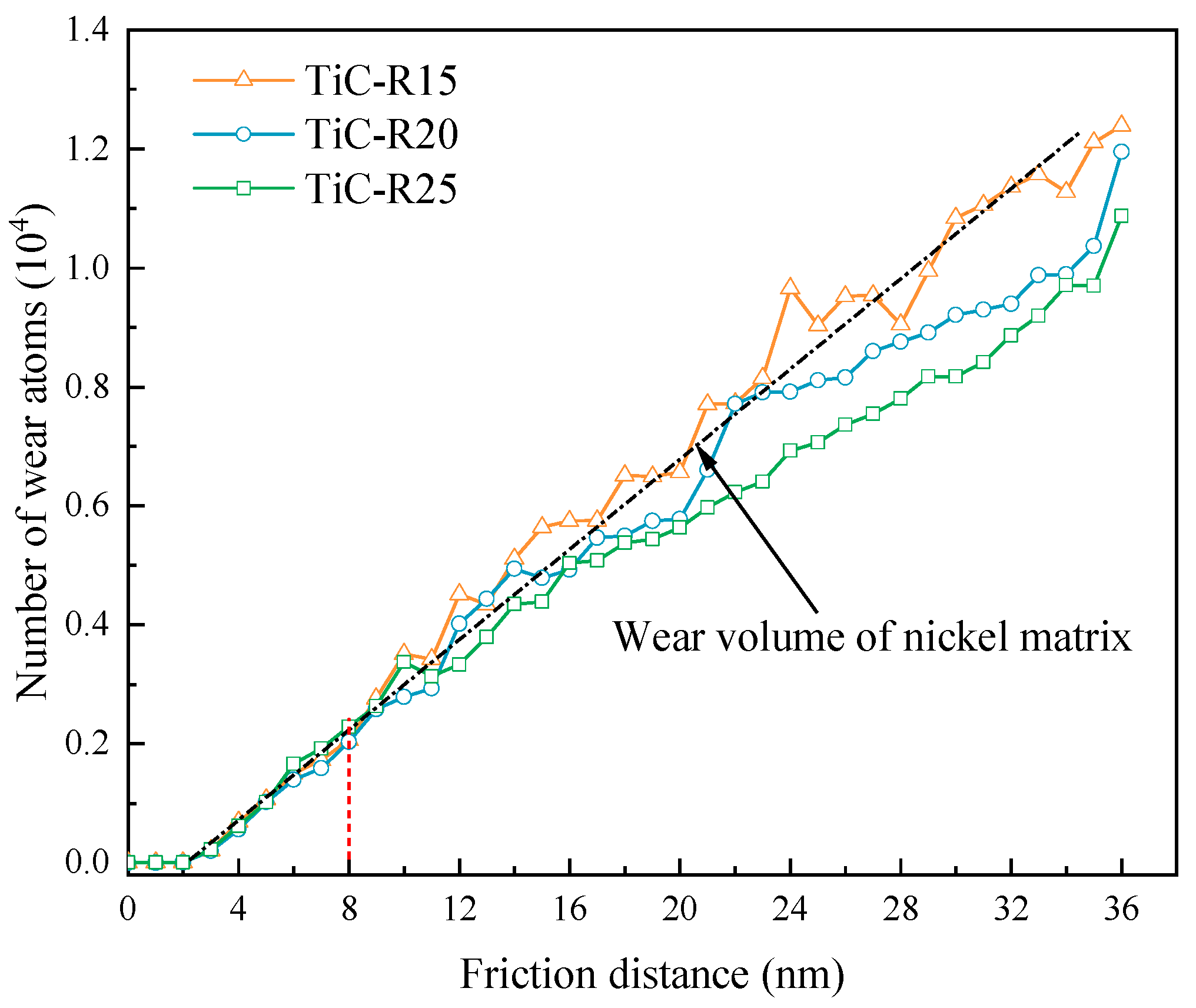
Figure 27 shows the wear atomic number of TiC particles workpieces with different radii. One can see that the numbers of wear atoms for different radius TiC particles were the same at the initial stage of friction (less than 8 nm). However, with the increase in the friction distance, the grinding ball kept approaching the TiC particles, and the TiC particles gradually exerted an effect on the workpiece, resulting in a decreasing number of wear atoms with increasing radius at the same friction distance. In addition, the number of wear atoms of workpieces with radii of 20 and 25 Å was significantly less than that of the nickel matrix, while the number of wear atoms of workpieces with a radius of 15 Å and that of the nickel matrix were approximately the same and accompanied by large fluctuations. The above demonstrated that the TiC particles assumed the strengthening phase capability, and the anti-wear capability of the workpiece kept improving as the radius of the TiC particles increased.

4. Conclusions

In this study, the influence on the tribological behavior of a nickel matrix of the distribution characteristics of ceramic-reinforced TiC was systematically investigated using the MD method. The insights gained not only contribute to the understanding of the influence of TiC particle distribution on the wear mechanism of the nickel matrix, but can also facilitate the further application of TiC/Ni composites. The detailed conclusions are as follows:
  • When the depth of the reinforced TiC particles is decreasing, the frictional and normal forces continuously decrease, and the shallower the depth of the workpiece, the easier it is to produce vacancy/interstitial atoms with difficult dislocation slip, leading to friction hardening that reduces the friction coefficient and wear volume. The same results are produced as the radius of the TiC particles increases. However, the increasing radius causes the dislocation density to increase, resulting in the increasing normal force.
  • With the decreasing depth or increasing radius of the TiC particles, it is easier to produce a local stress concentration between the TiC particles and grinding ball, which will, in turn, promote the nucleation of dislocations. The TiC particles block the development and extension of dislocations, leading to the formation of a high dislocation density zone, which will cause interaction between the dislocations and form barriers to dislocation movement, thus increasing the deformation resistance of the workpiece.
  • TiC particles with a large radius and shallow depths are more prone to defects. However, the subsurface damage depth is small and has a strong ability to protect the workpiece interior. Meanwhile, the defects between the TiC particles and grinding ball are fine; dislocation entanglement and atomic clustering occur, resulting in difficult deformation of the workpiece material. The atomic displacement trend is inconsistent with the direction of the slip system due to the presence of TiC, reducing the Z-directional movement of the atoms.
  • The shallower the depth of the TiC particles distribution, the stronger the extrusion of atoms between the TiC particles and grinding ball, increasing the potential energy of nickel atoms; however, the region of high-temperature nickel atoms above the TiC particles is reduced, and the TiC particles have a thermal insulation effect, putting the nickel atoms below in a low-temperature state and improving the high-temperature performance of the workpiece. However, the large-radius TiC particles at the same depth tend to cause the surrounding nickel atoms and TiC particles to be in a high-temperature state, and the ability to absorb the action of the grinding ball is strong, allowing the workpiece to reach a stable temperature more quickly.

Author Contributions

Conceptualization, M.Z. and Z.Z.; Methodology, M.Z.; Validation, W.C. (Weihua Chen); Investigation, W.C. (Wenbang Chen); Data curation, T.S. and J.C.; Writing—original draft, D.Q.; Writing—review & editing, Z.Z. All authors have read and agreed to the published version of the manuscript.

Funding

This work was supported by the National Natural Science Foundation of China (52265025).

Data Availability Statement

Data can be provided on request due to privacy or ethical restrictions.

Conflicts of Interest

The authors declare that we have no known competing financial interest or personal relationship that could have appeared to influence the work reported in this paper.

References

  1. Liao, Z.; Abdelhafeez, A.; Li, H.; Yang, Y.; Diaz, O.G.; Axinte, D. State-of-the-art of surface integrity in machining of metal matrix composites. Int. J. Mach. Tools Manuf. 2019, 143, 63–91. [Google Scholar] [CrossRef]
  2. Shu, R.; Jiang, X.S.; Sun, H.L.; Shao, Z.; Song, T.; Luo, Z. Recent researches of the bio-inspired nano-carbon reinforced metal matrix composites. Compos. Part A Appl. Sci. Manuf. 2020, 131, 105816. [Google Scholar] [CrossRef]
  3. Shu, R.; Jiang, X.S.; Shao, Z.Y.; Sun, D.; Zhu, D.; Luo, Z. Fabrication and mechanical properties of MWCNTs and graphene synergetically reinforced Cu-graphite matrix composites. Powder Technol. 2019, 349, 59–69. [Google Scholar] [CrossRef]
  4. Ma, Y.; Chen, H.; Zhang, M.-X.; Addad, A.; Kong, Y.; Lezaack, M.B.; Gan, W.M.; Chen, Z.; Ji, G. Break through the strength-ductility trade-off dilemma in aluminum matrix composites via precipitation-assisted interface tailoring. Acta Mater. 2022, 242, 118470. [Google Scholar] [CrossRef]
  5. Gu, D.; Cao, S.; Lin, K. Laser Metal Deposition Additive Manufacturing of TiC Reinforced Inconel 625 Composites: Influence of the Additive TiC Particle and Its Starting Size. J. Manuf. Sci. Eng. 2016, 139, 200–210. [Google Scholar] [CrossRef]
  6. Xu, L.F.; Xiao, R.; Qu, G.; Wang, D.S. In Situ Synthesized Graded TiC Particulate Reinforced Ni-based Composite Coating Prepared by Laser Cladding. J. Phys. Conf. Ser. 2021, 1820, 012050. [Google Scholar] [CrossRef]
  7. Fernández, M.; García, A.; Cuetos, J.; González, R.; Noriega, A.; Cadenas, M. Effect of actual WC content on the reciprocating wear of a laser cladding NiCrBSi alloy reinforced with WC. Wear 2015, 324, 80–89. [Google Scholar] [CrossRef]
  8. Han, Q.Q.; Gu, Y.C.; Huang, J.; Wang, L.Q.; Low, K.W.; Feng, Q.; Yin, Y.; Setchi, R. Selective laser melting of Hastelloy X nanocomposite: Effects of TiC reinforcement on crack elimination and strength improvement. Compos. Part B Eng. 2020, 202, 108442. [Google Scholar] [CrossRef]
  9. Xu, J.Q.; Chen, L.Y.; Choi, H.; Li, X.C. Theoretical study and pathways for nanoparticle capture during solidification of metal melt. J. Phys. Condens. Matter 2012, 24, 255304. [Google Scholar] [CrossRef]
  10. Pasha, M.B.; Kaleemulla, M. Processing and characterization of aluminum metal matrix composites: An overview. Rev. Adv. Mater. Sci. 2018, 56, 79–90. [Google Scholar] [CrossRef]
  11. Lee, T.; Chae, H.; Shin, S.; Cho, S.; Lee, S.-K.; Lee, S.Y.; An, K.; Ryu, H.J. Overcoming brittleness of high volume fraction Al/SiCp composites by controlling interface characteristics. Mater. Des. 2022, 222, 111038. [Google Scholar] [CrossRef]
  12. Ma, L.S.; Zhang, X.; Pu, B.W.; Zhao, D.D.; He, C.; Zhao, N. Achieving the strength-ductility balance of boron nitride nanosheets/Al composite by designing the synergistic transition interface and intragranular reinforcement distribution. Compos. Part B Eng. 2022, 246, 110243. [Google Scholar] [CrossRef]
  13. Liu, Y.; Tang, X.H.; Zhou, S.F.; Guo, B.S.; Zhang, Z.-g.; Li, W. Improving mechanical properties of Cu/Ti3AlC2 composites via in-situ decomposed gradient interfaces. Mater. Sci. Eng. A 2022, 834, 142615. [Google Scholar] [CrossRef]
  14. Wu, Z.X.; Jiang, X.S.; Sun, H.L.; Shao, Z.Y.; Shu, R.; Zhang, Y.; Fang, Y. Nano/Micro-scale numerical simulation and microscopic analysis on metal/oxide interfaces: A review. Compos. Part A Appl. Sci. Manuf. 2022, 163, 107184. [Google Scholar] [CrossRef]
  15. Rezayat, M. Deformation mechanism in particulate metal matrix composites. J. Alloys. Compd. 2022, 890, 161512. [Google Scholar] [CrossRef]
  16. Zhang, Z.; Wang, R.; Lv, Y.T.; Liu, W.; Liu, Y. Microstructures and mechanical properties of heat treated TiC/GTD222 nickel-based composite prepared by selective laser melting. Mater. Sci. Eng. A 2022, 851, 143588. [Google Scholar] [CrossRef]
  17. Yu, X.L.; Ma, C.Y.; Yao, L.M.; Xiao, Z.; Ren, Y. Microstructures and properties of nickel-titanium carbide composites fabricated by laser cladding. Ceram. Int. 2022, 48, 21773–21780. [Google Scholar] [CrossRef]
  18. Liu, X.; Liu, Z.L.; Zhang, L.T.; Zhao, Q.; Jiang, Q. Increased tensile strength and elongation of the Ni–Fe based polycrystalline cast superalloy via the trace addition of TiC nanoparticles. Mater. Sci. Eng. A 2021, 827, 141988–141994. [Google Scholar] [CrossRef]
  19. Domitner, J.; Silvayeh, Z.; Buzolin, R.H.; Krisam, S.; Achterhold, K.; Povoden-Karadeniz, E.; Sommitsch, C.; Mayr, P. Microstructure Characterization of Nickel Matrix Composite Reinforced with Tungsten Carbide Particles and Produced by Laser Cladding. Adv. Eng. Mater. 2022, 24, 2200463. [Google Scholar] [CrossRef]
  20. Testa, V.; Morelli, S.; Bolelli, G.; Lusvarghi, L.; Björklund, S.; Joshi, S. Micromechanical behaviour and wear resistance of hybrid plasma-sprayed TiC reinforced Tribaloy-400. Surf. Coat. Technol. 2021, 425, 127682. [Google Scholar] [CrossRef]
  21. Li, R.W.; Chen, Q.C.; Zhang, Z.L.; Ouyang, L.; Zhang, Y.; Nie, B.; Ding, Y. Revealing the atomic-scale structure and the fracture mechanism of the α-Al2O3/γ-Fe ceramic-metal interface. J. Alloys. Compd. 2021, 885, 161163. [Google Scholar] [CrossRef]
  22. Sun, Y.; Wang, J.M.; Guo, J.X.; Zu, Q.; Huang, J.; Peng, Q. Atomic-scale oxidation mechanisms of single-crystal magnesium. Nanoscale 2019, 11, 23346–23356. [Google Scholar] [CrossRef] [PubMed]
  23. Yu, W.S.; Shen, S.P. Multiscale study on the tensile fracture of Al-terminated Cu (1 1 1)/α-Al2O3 (0 0 0 1) interfaces. Comput. Mater. Sci. 2010, 48, 228–240. [Google Scholar] [CrossRef]
  24. Mengis, L.; Grimme, C.; Galetz, M.C. Tribological properties of the uncoated and aluminized Ti–48Al–2Cr–2Nb TiAl alloy at high temperatures. Wear 2021, 477, 203818. [Google Scholar] [CrossRef]
  25. Yuan, Z.J.; Lee, W.B.; Yao, Y.X.; Zhou, M. Effect of crystallographic orientation on cutting forces and surface quality in diamond cutting of single crystal. CIRP Ann. 1994, 43, 39–42. [Google Scholar] [CrossRef]
  26. Xu, Y.; Wang, M.C.; Zhu, F.L.; Liu, X.J.; Chen, Q.; Hu, J.; Lu, Z.; Zeng, P.; Liu, Y. A molecular dynamic study of nano-grinding of a monocrystalline copper-silicon substrate. Appl. Surf. Sci. 2019, 493, 933–947. [Google Scholar] [CrossRef]
  27. Xu, S.; Wan, Q.; Sha, Z.; Liu, Z. Molecular dynamics simulations of nano-indentation and wear of the γTi-Al alloy. Comput. Mater. Sci. 2015, 110, 247–253. [Google Scholar] [CrossRef]
  28. Zheng, M.; Qu, D.F.; Wei, X.C.; Zhang, Z.; Zhu, Z.; Wang, L.; Chen, W. Molecular dynamics study on the nanoscale repeated friction and wear mechanisms of TiC/Ni composites. Appl. Phys. A 2022, 128, 294. [Google Scholar] [CrossRef]
  29. Xu, F.; Fang, F.; Zhang, X. Hard particle effect on surface generation in nano-cutting. Appl. Surf. Sci. 2017, 425, 1020–1027. [Google Scholar] [CrossRef]
  30. Fu, R.; Rui, Z.Y.; Feng, R.C.; Dong, Y.; Lv, X. Effects of γ/γ lamellar interfaces on translamellar crack propagation in TiAl alloys. J. Alloys. Compd. 2022, 918, 165616. [Google Scholar] [CrossRef]
  31. Xu, Q.; Li, W.; Zhou, J.X.; Yin, Y.J.; Nan, H.; Feng, X. Molecular dynamics study on void collapse in single crystal hcp-Ti under hydrostatic compression. Comput. Mater. Sci. 2020, 171, 109280. [Google Scholar] [CrossRef]
  32. Yin, Q.; Lian, Y.D.; Wen, Z.X.; Pei, H.Q.; Wang, J.; Yue, Z. Atomic simulation of the effect of orientation on tensile/compressive properties in nickel-based single crystal superalloys. J. Alloys. Compd. 2022, 893, 162210. [Google Scholar] [CrossRef]
  33. Shao, J.; Xiao, B.; Wang, Q.; Ma, Z.; Yang, K. An enhanced FEM model for particle size dependent flow strengthening and interface damage in particle reinforced metal matrix composites. Compos. Sci. Technol. 2011, 71, 39–45. [Google Scholar] [CrossRef]
  34. Dai, H.F.; Li, S.B.; Chen, G.Y. Molecular dynamics simulation of subsurface damage mechanism during nanoscratching of single crystal silicon. Proc. Inst. Mech. Eng. Part J J. Eng. Tribol. 2019, 233, 61–73. [Google Scholar] [CrossRef]
  35. Nosé, S. A unified formulation of the constant temperature molecular dynamics methods. J. Chem. Phys. 1984, 81, 511–519. [Google Scholar] [CrossRef] [Green Version]
  36. Verlet, L. Computer “experiments” on classical fluids. I. Thermodynamical properties of Lennard-Jones molecules. Phys. Rev. 1967, 159, 98. [Google Scholar] [CrossRef] [Green Version]
  37. Hao, Z.P.; Lou, Z.Z.; Fan, Y.H. Study on the evolution mechanism of subsurface defects in nickel-based single crystal alloy during atomic and close-to-atomic scale cutting. J. Manuf. Process. 2021, 68, 14–33. [Google Scholar] [CrossRef]
  38. Yin, Z.; Zhu, P.; Li, B. Study of Nanoscale Wear of SiC/Al Nanocomposites Using Molecular Dynamics Simulations. Tribol. Lett. 2021, 69, 38. [Google Scholar] [CrossRef]
  39. Kraska, T. Molecular-dynamics simulation of argon nucleation from supersaturated vapor in the NVE ensemble. J. Chem. Phys. 2006, 124, 054507. [Google Scholar] [CrossRef] [Green Version]
  40. Baskes, M.I. Modified embedded-atom potentials for cubic materials and impurities. Phys. Rev. B 1992, 46, 2727. [Google Scholar] [CrossRef]
  41. Kim, Y.-M.; Lee, B.-J. Modified embedded-atom method interatomic potentials for the Ti-C and Ti-N binary systems. Acta Mater. 2008, 56, 3481–3489. [Google Scholar] [CrossRef]
  42. Lee, B.-J.; Baskes, M. Second nearest-neighbor modified embedded-atom-method potential. Phys. Rev. B 2000, 62, 8564. [Google Scholar] [CrossRef]
  43. Foiles, S.M.; Baskes, M.I.; Daw, M.S. Embedded-atom-method functions for the fcc metals Cu, Ag, Au, Ni, Pd, Pt, and their alloys. Phys. Rev. B 1986, 33, 7983–7991. [Google Scholar] [CrossRef] [PubMed]
  44. Hao, Z.P.; Cui, R.R.; Fan, Y.H.; Lin, J.Q. Diffusion mechanism of tools and simulation in nanoscale cutting the Ni-Fe-Cr series of Nickel-based superalloy. Int. J. Mech. Sci. 2019, 150, 625–636. [Google Scholar] [CrossRef]
  45. Tersoff, J. Modeling solid-state chemistry: Interatomic potentials for multicomponent systems. Phys. Rev. B 1989, 39, 5566. [Google Scholar] [CrossRef]
  46. Maekawa, K.; Itoh, A. Friction and tool wear in nano-scale machining—A molecular dynamics approach. Wear 1995, 188, 115–122. [Google Scholar] [CrossRef]
  47. Fang, Q.H.; Wang, Q.; Li, J.; Zeng, X.; Liu, Y.W. Mechanisms of subsurface damage and material removal during high speed grinding processes in Ni/Cu multilayers using a molecular dynamics study. RSC Adv. 2017, 7, 42047–42055. [Google Scholar] [CrossRef] [Green Version]
  48. Bernard, J.E. The simulation of coulomb friction in mechanical systems. Simulation 1980, 34, 11–16. [Google Scholar] [CrossRef]
  49. Mohammadi, S.; Montazeri, A.; Urbassek, H.M. Geometrical aspects of nanofillers influence the tribological performance of Al-based nanocomposites. Wear 2020, 444, 203117. [Google Scholar] [CrossRef]
  50. Jiang, L.; Yang, H.; Yee, J.K.; Mo, X.; Topping, T.; Lavernia, E.J.; Schoenung, J.M. Toughening of aluminum matrix nanocomposites via spatial arrays of boron carbide spherical nanoparticles. Acta Mater. 2016, 103, 128–140. [Google Scholar] [CrossRef]
  51. Peng, Q.; Meng, F.J.; Yang, Y.Z.; Lu, C.Y.; Deng, H.Q.; Wang, L.M.; De, S.; Gao, F. Shockwave generates<100> dislocation loops in bcc iron. Nat. Commun. 2018, 9, 4880. [Google Scholar] [CrossRef]
  52. Rycroft, C.H.; Grest, G.S.; Landry, J.W.; Bazant, M.Z. Analysis of granular flow in a pebble-bed nuclear reactor. Phys. Rev. E 2006, 74, 021306. [Google Scholar] [CrossRef] [Green Version]
  53. Hao, Z.; Lou, Z.; Fan, Y. Study on staged work hardening mechanism of nickel-based single crystal alloy during atomic and close-to-atomic scale cutting. Precis. Eng. 2021, 68, 35–56. [Google Scholar] [CrossRef]
  54. Bai, L.; Srikanth, N.; Korznikova, E.A.; Baimova, J.A.; Dmitriev, S.V.; Zhou, K. Wear and friction between smooth or rough diamond-like carbon films and diamond tips. Wear 2017, 372, 12–20. [Google Scholar] [CrossRef]
  55. Guo, J.; Chen, J.J.; Lin, Y.Z.; Liu, Z.M.; Wang, Y.Q. Effects of surface texturing on nanotribological properties and subsurface damage of monocrystalline GaN subjected to scratching investigated using molecular dynamics simulation. Appl. Surf. Sci. 2021, 539, 148277. [Google Scholar] [CrossRef]
  56. Zhu, Z.X.; Peng, B.; Feng, R.C.; Wang, L.J.; Jiao, S.; Dong, Y. Molecular dynamics simulation of chip formation mechanism in single-crystal nickel nanomachining. Sci. China Technol. Sci. 2019, 62, 1916–1929. [Google Scholar] [CrossRef]
  57. Bailey, J.; Hirsch, P. The dislocation distribution, flow stress, and stored energy in cold-worked polycrystalline silver. Philos. Mag. 1960, 5, 485–497. [Google Scholar] [CrossRef]
  58. Zhang, X.D.; Godfrey, A.; Huang, X.X.; Hansen, N.; Liu, Q. Microstructure and strengthening mechanisms in cold-drawn pearlitic steel wire. Acta Mater. 2011, 59, 3422–3430. [Google Scholar] [CrossRef]
  59. Zhang, J.; Sun, T.; Yan, Y.; Liang, Y.; Dong, S. Molecular dynamics simulation of subsurface deformed layers in AFM-based nanometric cutting process. Appl. Surf. Sci. 2008, 254, 4774–4779. [Google Scholar] [CrossRef]
Figure 1. TiC/Ni composite workpiece.
Lubricants 11 00083 g001
Figure 2. Variation of (a) friction and (b) normal forces of TiC/Ni composites with friction distance at different depths.
Lubricants 11 00083 g002
Figure 3. Average value of friction and normal force under different depths.
Lubricants 11 00083 g003
Figure 4. Stress distribution nephogram and number of high-stress atoms versus friction distance curve. (a–c) is the local stress diagram with the depth of 20, 30, 40 Å respectively.
Lubricants 11 00083 g004
Figure 5. Dislocation distribution of TiC particles at different depths.
Lubricants 11 00083 g005
Figure 6. Dislocation length diagram under different depths.
Lubricants 11 00083 g006
Figure 7. Dislocation number diagram of the grinding ball positive pressure TiC particles under different depths.
Lubricants 11 00083 g007
Figure 8. Defects inside workpieces with different TiC particles depths. The atoms with the hexagonal close-packed (HCP) structure were colored red, the atoms of the body-centered cubic (BCC) structure were colored blue, the amorphous atoms were colored white.
Lubricants 11 00083 g008
Figure 9. The number of HCP structure atoms in TiC/Ni composites.
Lubricants 11 00083 g009
Figure 10. The number of vacancy/interstitial atoms varies with the friction distance.
Lubricants 11 00083 g010
Figure 11. Morphology of wear scar depth after friction under different depths; (ac) are friction distances of 13, 23, and 33 nm, respectively.
Lubricants 11 00083 g011
Figure 12. Different position displacement vector displays. (ac) represent typical displacement vectors with depths of 20, 30, and 40 Å, respectively (D1 < D2 < D3).
Lubricants 11 00083 g012
Figure 13. Nickel atomic displacement for different TiC particles depths. (ac) represent displacement scatter plots with depths of 20, 30 and 40 Å respectively.
Lubricants 11 00083 g013
Figure 14. The number of wear atoms in TiC/Ni composites.
Lubricants 11 00083 g014
Figure 15. The number of displaced atoms in the TiC particles.
Lubricants 11 00083 g015
Figure 16. Atomic potential energy distribution of workpiece under different depths.
Lubricants 11 00083 g016
Figure 17. Variation of the number of nickel atoms at 700–1200 K under different depths; (ac) are temperature nephograms with depths of 20, 30, and 40 Å respectively.
Lubricants 11 00083 g017
Figure 18. Variation curve of TiC particles atomic temperature with friction distance; (ac) are depths of 20, 30, and 40 Å, respectively.
Lubricants 11 00083 g018
Figure 19. Statistics of the number of nickel atoms at the temperature of 300–700 K; (ac) are the number of atoms at friction distances of 13, 23, and 33 nm, respectively.
Lubricants 11 00083 g019
Figure 20. Vacancy/interstitial atoms in different TiC particles radii during the friction process.
Lubricants 11 00083 g020
Figure 21. Variation of dislocation density with friction distance; (ac) are TiC particles with radii of 25, 20, and 15 Å, respectively.
Lubricants 11 00083 g021
Figure 22. Average value of friction force and normal force of different TiC particles radii.
Lubricants 11 00083 g022
Figure 23. (ac) Von Mises stress distribution of TiC particles workpieces with different radii when the grinding ball is under positive pressure on TiC particles. (df) Workpiece temperature distribution of TiC particles workpieces with different radii when the grinding ball is under positive pressure on TiC particles.
Lubricants 11 00083 g023
Figure 24. (a) Proportion of nickel atoms with stress higher than 6 Gpa in total nickel atoms during friction. (b) Proportion of nickel atoms with temperature higher than 500 K in total nickel atoms during friction.
Lubricants 11 00083 g024
Figure 25. Average damage thickness and elastic recovery rate in different TiC particles radii.
Lubricants 11 00083 g025
Figure 26. The number of HCP structure atoms in TiC/Ni composites.
Lubricants 11 00083 g026
Figure 27. Number of wear atoms at different TiC particles radii.
Lubricants 11 00083 g027
Table 1. MD simulation parameters.
MaterialsModel 1Model 2Tool: Diamond
Dimensions40 × 16 × 18 nm40 × 16 × 18 nmSpherical: R = 3 nm
Atomic number1052098About 1.052 million20139
Depth of TiC particles (TiC-ΔD)20, 30, 40 Å
Radius of TiC particles (TiC-ΔR) 15, 20, 25 Å
Material of workpieceTiC/Ni Composites
Interatomic potentialEAM Morse MEAM/cTersoff
Initial temperature300 k
Timestep1 fs
Grinding velocity10−3 Å/fs
Grinding depth1 nm
Grinding length36 nm
Grinding direction[−1 0 0] on (0 0 1) surface, -X direction
Table 2. Elastic recovery rate ε.
TiC-D20TiC-D30TiC-D40
D = 13 nm8.127%21.973%23.147%
D = 23 nm4.733%9.873%12.647%
D = 33 nm0.053%4.447%6.580%
Disclaimer/Publisher’s Note: The statements, opinions and data contained in all publications are solely those of the individual author(s) and contributor(s) and not of MDPI and/or the editor(s). MDPI and/or the editor(s) disclaim responsibility for any injury to people or property resulting from any ideas, methods, instructions or products referred to in the content.

