1. Introduction
Coated and layered materials are commonly used in numerous engineering applications. The main purpose of a coating technology is significant improvement of the performance of certain devices or their parts, as changing the properties of the surface can dramatically affect the behavior of the material. Coating technology is often applied to enhance the properties of the materials that are involved in mechanical contacts, to modify their tribological properties, and to improve wear resistance, adhesion, friction, etc [
1]. Furthermore, coatings are also used to achieve the desired level of biocompatibility of implants [
2,
3], to obtain needed optical properties [
4], to enable triboelectric energy harvesting [
5], and for many other technologies. Therefore, development of experimental, numerical and analytical techniques for the modelling and studying of materials with a layered structure is an important topic in various fields of science and technology.
Most of the analytical theories and numerical simulation methods used for describing elastic contacts make use of “half-space approximation”, wherein an object with finite sizes at certain conditions can be considered as a half-space. This approximation can be applied to bodies coated with an elastic substrate provided the characterized size,
D, of the contact area is much smaller than the thickness of the coating [
6]. A special case of a coated body is an elastic layer placed on the rigid substrate. If an elastic layer with thickness
h is indented by a cylindrical indenter of diameter
D, this layer can be considered as a half-space provided the thickness of the layer is much larger than the diameter of indenter. Classical theories of adhesion, such as JKR [
7], DMT [
8] or Maugis theory [
9], as well as the classic Hertz theory [
10], all operate in the half-space approximation; therefore, much of our intuitive understanding of contacts is based implicitly on the results of half-space approximation. However, if the contact size is comparable with the layer thickness, the use of the half-space approximation may lead to inadequate results so that the finite size has to be taken into account. There is a number of theories considering these corrections [
11,
12,
13,
14,
15,
16].
In addition to purely analytical methodology, numerical simulations are also widely used for solving the contact tasks involving layers of a given thickness. Commonly used numerical methods are the finite element method (FEM) [
17,
18,
19] and the Fourier-based residuals molecular dynamics (RMD) [
20], among others [
21]. At present, the FFT-assisted boundary element method (BEM) is considered the most powerful technique for simulation contacts. Recently, it was generalized for the case of coated elastic half-space and also takes adhesion into account [
22]. In the described generalization, adhesion is considered in the “JKR-limit”, meaning that the range of action of adhesive forces is much smaller than any other characteristic length of the problem (including gap and indentation depth) so that it can be considered to be zero. It is not automatically guaranteed that this condition is fulfilled in real adhesive contacts. Thus, it is important to “verify” the simulation method through comparison with experiments. This comparison is the main purpose of the present paper.
2. Materials and Methods
As mentioned in introduction, in our study we used FFT-based BEM for coated half-space [
22]. This approach was recently implemented for a description of adhesive and non-adhesive contacts between rigid indenter and elastic half-space coated with a layer of different elastic properties. Within BEM, an elastic half-space with elastic modulus
E2 and Poisson ratio ν
2 coated with the elastic layer of thickness
h and elastic parameters
E1 and ν
1 is considered. To solve the contact problem between coated half-space and a rigid indenter with arbitrary geometry numerically, we consider a square region on the body surface with the size
L ×
L, which has
N cells in each direction, while the size of each of the
N2 square cells is Δ
x = Δ
y = Δ. Pressure is assumed to be uniform in each cell. If the pressure distribution
p is given, the displacement
u can be calculated according to a numerical procedure [
22],
where
uz is a Fourier-transformed fundamental solution (normal displacements at the contact surface), and the analytical formula for
uz is provided in [
22]. The contact problem is solved iteratively. In each step, the displacements
u for a given pressure distribution
p are determined through the evaluation of Equation (1). The inverse problem of finding pressure
p for producing given deformations
u can be solved using the conjugate gradient method [
23]. For adhesive contacts, an additional detachment criterion is needed: a surface element at the boundary of the contact area loses its contact as soon as tensile stress in this element exceeds the critical value given by
where Δ
γ (J/m
2) is the specific work of adhesion between the indenter and substrate. For non-adhesive contacts, the detachment criterion is that normal pressure
p > 0; for adhesive contact the condition
p > –
σc must be used. Detailed information about numerical BEM procedure can be found in [
22].
Experiments concerning indenter–substrate contact are a well-known challenge in many fields of tribology, contact mechanics and nanotechnology [
24]. An experimental study of adhesive contacts between rigid indenters and elastic layers of different thickness was conducted on specially designed in-house laboratory equipment. Detailed description of the designed facility and examples of its performance are given in our recent paper [
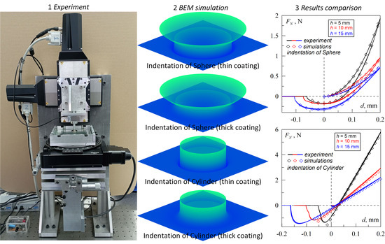
25]; therefore, here, we provide only brief information about the experimental setup. General view of the designed device together with an enlarged image of the indenter and sample are shown in
Figure 1.
The facility operates as a high-precision tribometer, which is capable of precise positioning of the sample in three dimensions and measuring all three components of the interaction force. All functional parts of the device that are denoted in the figure are the same for both panels: (1) and (2) are high-precision M-403.2DG motorized linear stages (manufactured by PI), which are handled by PI C-863 one-axis servo controllers; (3) is an ME K3D40 three-axis force sensor; (4) is an indenter that is mounted on the force sensor; (5) is the sample being indented placed at the 8 mm thick silicate glass plate; (6) is a tilt mechanism; (7) is a digital camera Ximea 2.2MP MQ022CG-CM with FUJINON HF16SA-1, 2/3” lens; and (8) is the 8MR190-90-4247-MEn1 motorized rotation stage. Various modifications of the developed device had already been used to perform several studies on contact mechanics [
25]. Below, we discuss experiments with indentation of hard steel indenters in soft elastic rubber sheets (elastomer) with good adhesive properties. As an elastomer, TARNAC CRG N3005 rubber sheets with linear sizes 100 mm × 100 mm × 5 mm were used (see
Figure 1b, position 5). In the experiments, elastomers with thickness
h = 5, 10, 15, 20 and 25 mm were used; to obtain the elastomer with different thickness, separate rubber sheets were stacked together. Due to the strong adhesion, these rubber sheets are firmly concatenated and did not slide over each other during the indentation. For indentation, cylinders with a flat base of diameter
D = 4, 7, 10 and 15 mm, as well as spheres with radii
R = 30, 50 and 100 mm, were used. All experiments were performed in laboratory under room temperature (24 ˚C) and relative humidity (48%).
3. Comparison of Computer Simulations and Analytical Solutions
In the case of indentation of the rigid cylindrical stamp with a flat base of radius
a into an elastic half-space, dependence of the normal force
F on indentation depth
d is defined by a classical expression:
where
E and
ν—elastic modulus and Poisson ratio of the elastic half-space. According to Equation (3), the contact stiffness can be expressed as:
Within half-space approximation, it is assumed that the contact radius
a is significantly smaller than the thickness of the indented elastic layer. In the case of a layer with thickness
h and elastic parameters
E and
ν placed onto rigid substrate, the approximate contact stiffness can be estimated using the expression [
11,
12]:
where small parameter
ε is introduced as
while the coefficients
ai are defined as
Approximation (5) is valid only in the case when the radius of contact a is smaller than the elastic layer thickness h and thus ε < 1 (6).
It is worth noting that in the opposite limit
ε >> 1, analytical approximation is also possible [
16,
26,
27]; however, this case will not be discussed here as we consider indentation into an elastomer, which is almost incompressible, and for such a material, the abovementioned analytics are in bad agreement with both simulation and experiments.
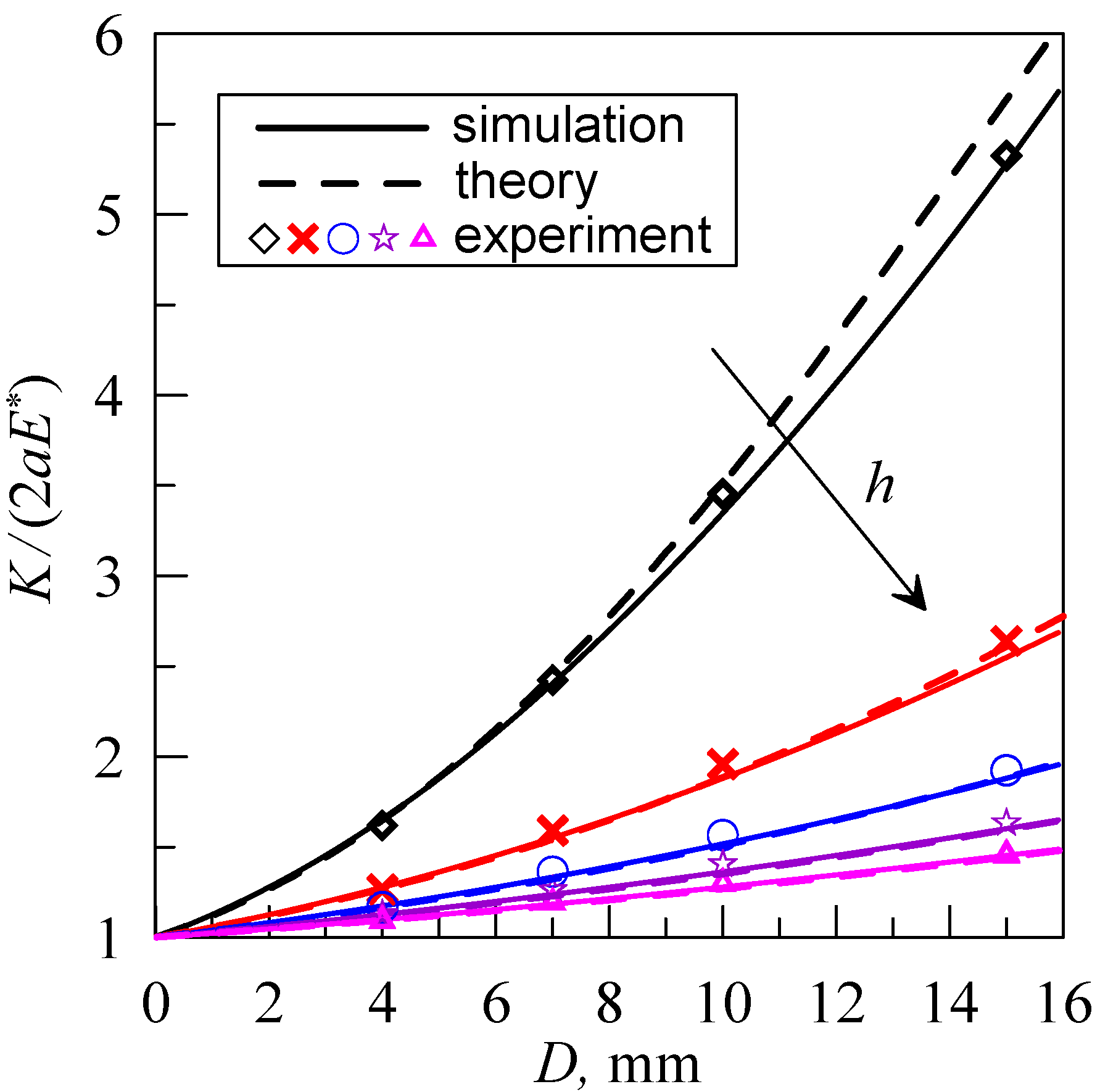
In
Figure 2, solid lines show the dependence of the contact stiffness
Ka<<h (5), normalized on half-space stiffness
Khalf space (4), while the thickness of elastic layer
h varies from 5 to 25 mm, with increments of 5 mm. Symbols in the figure show the results of the computer simulations within the BEM method. The horizontal dashed line shows the threshold
a =
h, i.e., when the layer thickness equals the radius of the indenter. Thus, the area of the plot located above threshold line relates to the values
ε =
a/
h > 1, and therefore, according to (5), (6) analytical approximation is expected not to be valid and may lead to incorrect results. However, as it can be seen from the figure, approximation (5) shows good agreement with simulations in a certain region of
ε > 1.
As follows from
Figure 2, the magnitude of
Ka<<h/2
aE* decreases when the layer thickness
h grows. In the limit case of infinite thickness
, the solution is reduced to the half-space approximation
Ka<<h/2
aE* = 1 when the contact stiffness does not depend on the indenter diameter. As it was mentioned in the Introduction, if the thickness of the indented substrate exceeds the diameter of the indenter, the substrate can be considered a half-space. However,
Figure 2 shows that in real contact, the half-space approximation is valid only for very large ratios
h/
D. For
h =
D = 5 mm, the stiffness ratio
Ka<<h/2
aE* ≈ 1.9 is almost 2, meaning that the contact stiffness is almost twice the half-space approximation. Curve
h = 5 mm reaches magnitude
Ka<<h/2
aE* = 1.2 at
D ≈ 1.55 mm. Therefore, half-space approximation leads to an error of 20% when
h/
D = 5/1.55 = 3.22, i.e., when the thickness of an elastomer exceeds the diameter of an indenter by more than three times. The restrictions of the half-space approximation were discussed in detail in our recent study [
28].
4. Experimental Verification of the Computer Simulations and Theoretical Model
Figure 3 shows dependencies of the normal force
FN on the indentation depth
d, obtained through the indentation of the cylinders with a flat base of diameter
D = 4, 7, 10 and 15 mm into layers of rubber TARNAC CRG N3005 of different thickness
h. Each panel of the figure shows five dependencies corresponding to the different magnitudes of the layer thickness:
h = 5, 10, 15, 20 and 25 mm. Solid lines are experimental results, while the results of the computer simulations are shown with symbols. Every dependence measured in an experiment at constant
D and
h consists of three curves obtained in three consecutive cycles of indentation. For all measurements, these curves visually overlap. Note that in all experiments, the velocity of indenter motion was equal to 1 µm/s in both directions. With this indenter velocity, the contact can be considered quasi-static and the viscoelasticity can be neglected [
29].
Considered contact between rubber and steel indenter is characterized by a strong adhesion; thus, in the regions related to the detachment
d < 0 mm, the magnitude of the normal force is negative
F < 0 N. However, while comparing the results of experiments with theory and simulations, we will consider only magnitudes of indentation depth
d > 0 mm where indenters with flat base exhibit exactly the same behavior in both adhesive and non-adhesive contacts. This can be explained by the fact that detachment of adhesive contact strongly depends on adhesion specific work, being a function of the surface energies of contacting bodies. Surface energy, meanwhile, is affected by the oxidation and dirt on the surface during the time of experiment. Thus, thorough cleaning of the surfaces is needed when the aim of the study is to detect the effect of the indenter radius, surface roughness, etc. Surfaces must be cleaned before each cycle of indentation strictly according to the predetermined procedure. In the presented experiments, such cleaning procedures were not performed as the adhesion phenomena were not the aim of the current study. As an example of the experiments on adhesion involving surface cleaning, we can refer to our previous work [
30].
Experimental dependencies
FN(
d) shown in
Figure 3 exhibit one distinguished feature: all obtained curves do not cross the coordinate origin, even when the zero indentation depth
d = 0 mm is theoretically corresponding to zero normal force
FN = 0 N. This feature is caused by certain peculiarities of the experiment, namely the presence of the asperities of various type on the surfaces of elastomer and indenter, and the impossibility of positioning substrate and indenter exactly parallel to each other. Thus, after the appearance of the first contact point, the contact area is spreading due to the adhesion, resulting in negative normal force
FN.
In the experiment, during the indentation phase, adhesive interaction between the surfaces is weaker compared to that in the pull-off phase. This well-known fact leads to secondary adhesive hysteresis and corresponding differences in
FN(
d) dependencies measured during indentation and pull-off [
30,
31,
32]. Such behavior can be described by introducing two different magnitudes of the adhesion specific work Δ
γ for both phases, respectively, where Δ
γ1 related to pull-off is significantly larger than Δ
γ0 related to indentation. We found that the contact of the steel indenters with elastomer TARNAC CRG N3005 is characterized by the empirically estimated value of Δ
γ0 = 0.0175 J/m
2 for indentation phase and a range of values Δ
γ1 from about 0.3 to 1 J/m
2 for pull-off [
33]. It is worth noting that larger-value Δ
γ1 can be reached by chemical treatment of the indenter. For instance, in ref. [
33], after short-time treatment of the surface of steel indenter with 40% water solution of FeCl
3, magnitudes of Δ
γ1 up to 13 J/m
2 were observed. Notably, even though chemical treatment significantly increases Δ
γ1, it has almost no effect on Δ
γ0 (which is related to contact propagation). Dependencies plotted using symbols in
Figure 3 show the results of BEM computer simulations related to the pull off of the indenter starting from maximal indentation depth
d = 0.2 mm. All simulations were performed with the same values of elastic and adhesive parameters:
E = 0.324 MPa,
ν = 0.48, Δ
γ1 = 0.326 J/m
2. Magnitudes of elastomer layer thickness
h in simulations were chosen to be the same as in the experiments. In the simulations, an elastic layer was located at the half-space substrate with elastic modulus equal to
E2 = 10
100 Pa. Such an extremely large value ensures absolute rigidity of the substrate in simulations. At the same time, in the experiment, rubber layers were placed on the 8 mm thick silicate glass substrate with an elastic modulus exceeding that of rubber by five orders of magnitude. This glass substrate was fixed on the aluminum table as it is shown in
Figure 1b.
On the other hand, within the BEM simulations, contacting surfaces are ideally flat and parallel to each other; therefore, all dependencies
FN(
d) obtained from simulations start from the coordinate origin, which makes it difficult to compare them to experimental data. With this purpose, theoretical curves were shifted to the right along the abscissa axis by Δ
d so both groups of data (theory and experiment) would overlap in the starting point
FN(Δ
d) = 0. Such type of data processing is applicable in our case, as it did not change the slope of
FN(
d) dependencies and corresponding contact stiffness
K = d
FN(
d)/d
d, which is the main subject of the current study. It is worth noting that another option for data correction is to shift experimental curves to the left as in ref. [
29]. Therein, both experimental and theoretical dependencies cross the coordinate origin.
Another important detail of the experimental setup is the preparation of the substrates of different thickness
h. To obtain the elastomer with a certain
h value, separate rubber sheets, each with
h = 5 mm, were stacked together. Due to the strong adhesion, these rubber sheets are firmly concatenated and did not slide over each other during the indentation. However, separate rubber sheets may have slightly different elastic properties and may thus cause an extra disagreement between experiments and simulations. Nevertheless, dependencies plotted in
Figure 3 show good agreement between the experimental results and simulations.
In all four panels of
Figure 3, dependencies
FN(
d) obtained for rubber layer with thickness
h = 5 mm show a distinctly high value of contact rigidity (highest slope of the
FN(
d) curve), while other
FN(
d) dependencies are characterized by close values of related contact rigidity, especially for higher
h. This situation is caused by the fact that with the growth of elastomer thickness
h, the conditions of the experiment become closer to the half-space approximation limit
h >>
D; thus, as the stiffness of the half-space
Khalf space =
2aE* is constant (at fixed indenter radius
a =
D/2), all curves behave similarly. For instance, in the experiment with indenter of a diameter
D = 4 mm (see
Figure 3a), the dependencies
FN(
d) measured for elastomers with thickness
h = 20 mm and 25 mm almost overlap as the ratio
h/
D equals 5 and 6.25, respectively, which practically satisfies the condition
h >>
D. The largest difference between measured
FN(
d) curves was observed in the experiment with indenter of largest diameter
D = 15 mm (see
Figure 3d) for elastomers of different thickness
h = 20 mm and 25 mm
h/
D ≈ 1.33 and 1.67, respectively.
As mentioned above (see description of
Figure 2), even at magnitude
h/
D = 3.22, application of half-space approximation leads to a contact stiffness reduction of 20%. Thus, all dependencies shown in
Figure 3d are not within the range of application of half-space approximation. For more detailed analysis, magnitudes of contact stiffness
K = d
FN/d
d were estimated from the experimental dependencies
FN(
d) shown in
Figure 3. Estimated values are plotted as symbols in
Figure 4.
Figure 4 also shows the contact stiffness calculated through the BEM simulations (solid lines) and theoretical approximation (5) (dashed lines).
Comparing dependencies obtained from the three different methods (experiment, simulations and theory), we can confirm the range determined earlier where the analytical solution can be applied, and also conclude that the experimental data are in good agreement with the computer simulations.
5. Discussion
In the closing part of our study, we discuss an additional series of experiments concerning indentation of the spherical indenters with different radii. In these experiments, steel spheres with radii
R = 30, 50 and 100 mm were indented into the rubber sheets with thickness
h = 5, 10, 15, 20 and 25 mm. The obtained results are shown in
Figure 5. As in the previous case, solid lines represent the experimental data obtained during three cycles of indentation in every experiment (measured curves are overlap), while symbols show the results of BEM simulations.
The conditions of the performed experiments are the same as in the experiment, the results of which are presented in
Figure 3, with the only difference being indentation with spherical indenters instead of cylindrical. The elastic parameters used for simulations are also the same:
E = 0.324 MPa,
ν = 0.48. However, in the computer experiment, both indentation and pull-off were also simulated. For the indentation phase, adhesion specific work was set equal to Δ
γ0 = 0.0175 J/m
2, while for the pull-off phase, it was chosen from the experimental data. Dependencies shown in
Figure 5 were obtained with the magnitudes of Δ
γ1 varying in the range from 0.27 J/m
2 to 0.722 J/m
2. Such a range of the Δ
γ1 values is caused by the specific feature of the experimental procedure, where surfaces of elastomer and indenter were not cleared after every cycle of indentation, which significantly affects the Δ
γ1.
Figure 5 shows good agreement between the simulation and the experiment, which confirms the accuracy of the performed calculations. It is important to note that elastic parameters of the elastomer were the same in each numerical experiment and were not adjusted to reproduce the experimental data. The only parameter that was adjusted in the simulation shown in
Figure 5 is the specific adhesion work in the pull-off phase Δ
γ1, which naturally changes after each cycle of the experiment.
It is worth noting that the theory of the adhesive contact of the parabolic indenter and elastic layer fixed on the elastic half-space is also presented in [
11]. The developed solution therein allows for the attainment of the dependence of the normal force
F on indentation depth
d, similar to the data shown in
Figure 5. Here, we are not comparing the results of simulations and experiments with the abovementioned work, as the accuracy of analytical approximation from [
11] has already been confirmed for cylindrical stamps. We expect similar agreement of the results obtained through the experiment and theory for any other shape of the indenter, as the theoretical solution obtained in ref. [
11] is based on the analytical formalism that defines elastic properties of the elastomer and is valid for any indenter shape [
11,
12]. Nevertheless, in our previous study [
34], we compared the results of BEM simulation with the theoretical solution from ref. [
11]. The comparison showed good agreement of all the data (theory, experiment and computer simulations) obtained in the experiment on indentation of the steel sphere with a radius
R = 33 mm into the rubber layer with a thickness
h = 25 mm.


