Numerical Simulation of a New Designed Mechanical Seals with Spiral Groove Structures


Abstract
:1. Introduction
2. Theory and Model
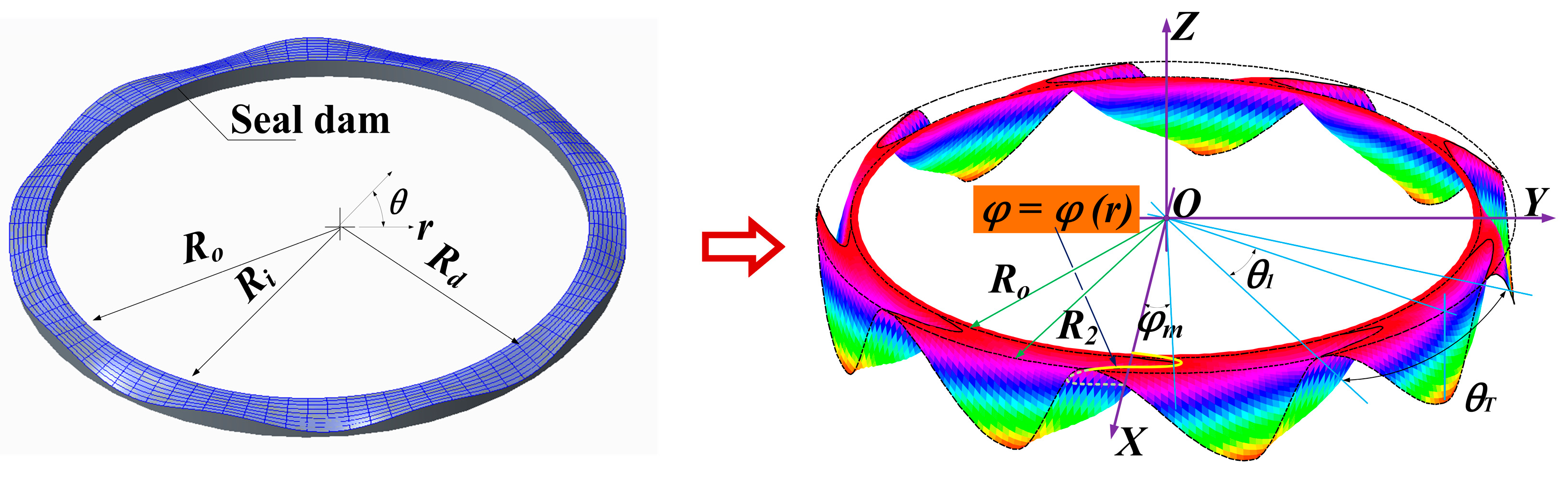
2.1. Geometry Model
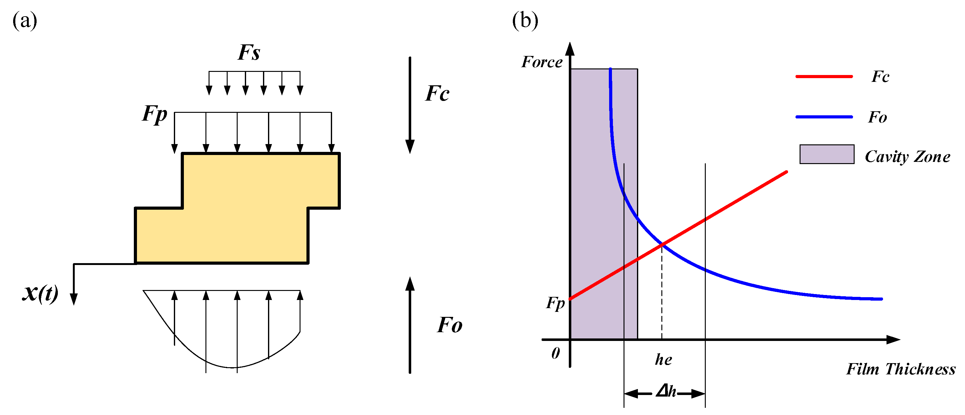
2.2. Kinematic Model
2.3. Finite Element Method
3. Results and Discussions
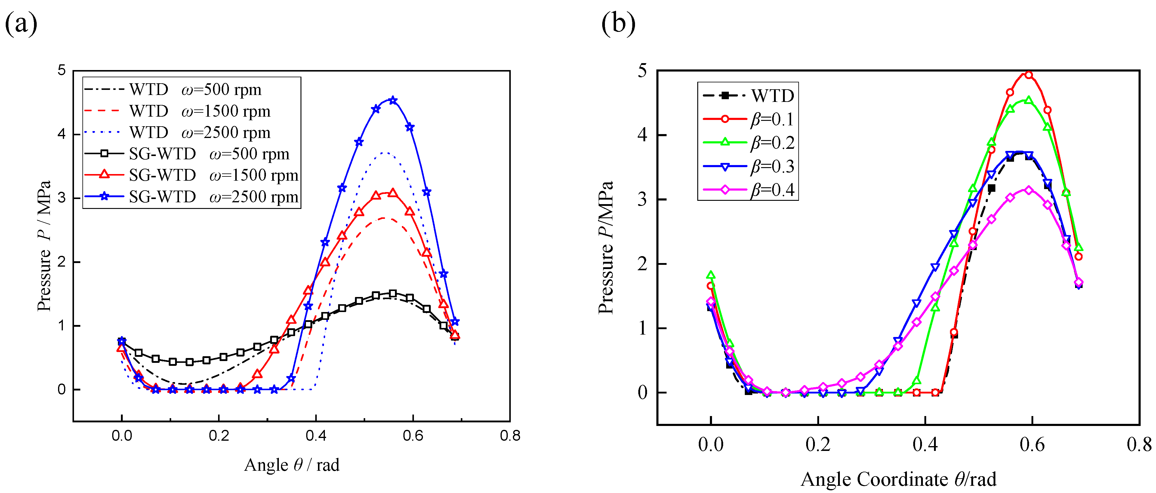
3.1. Pressure Distribution
3.2. Influence of Operation Parameters
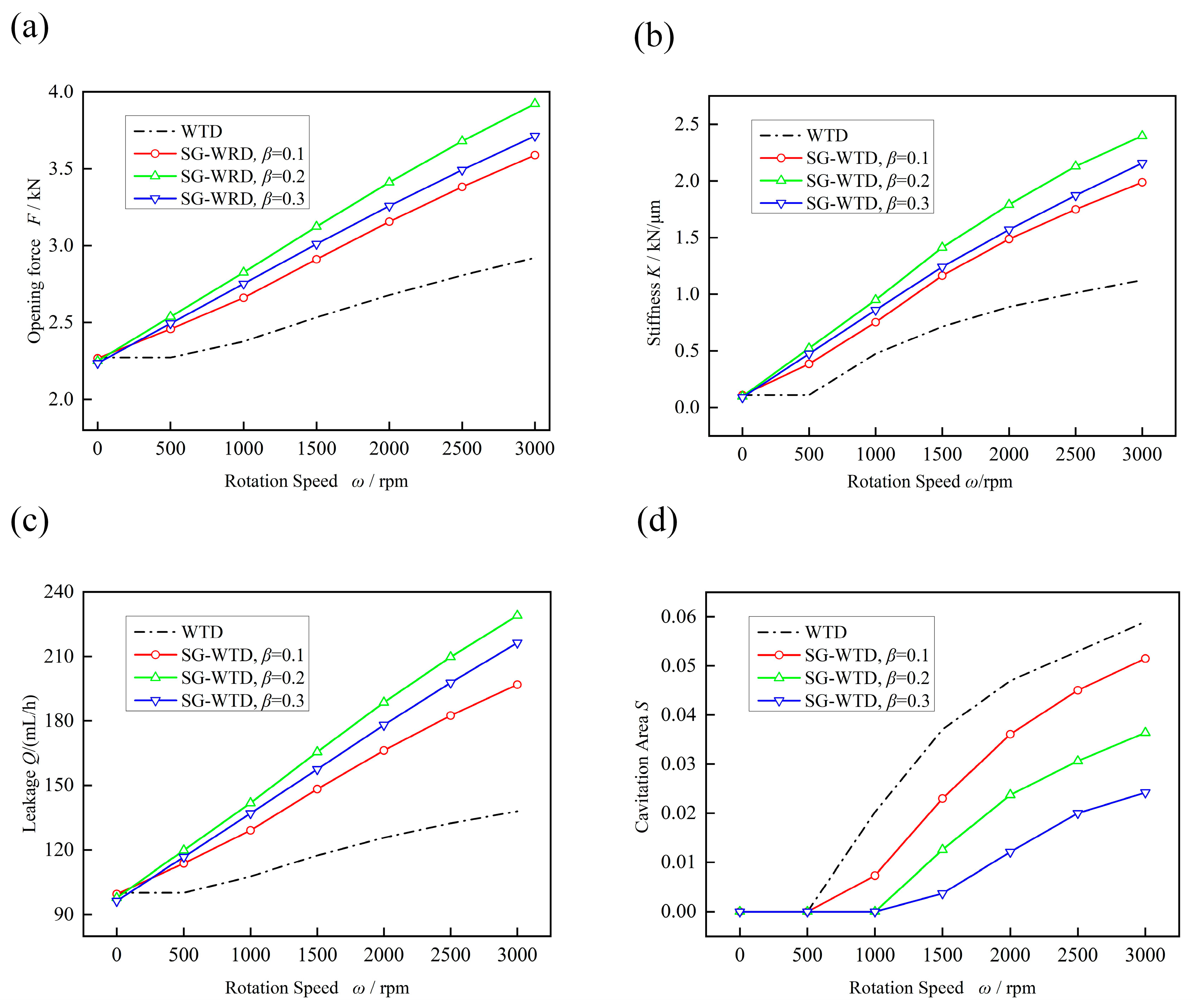
3.2.1. Influence of Rotation Speed
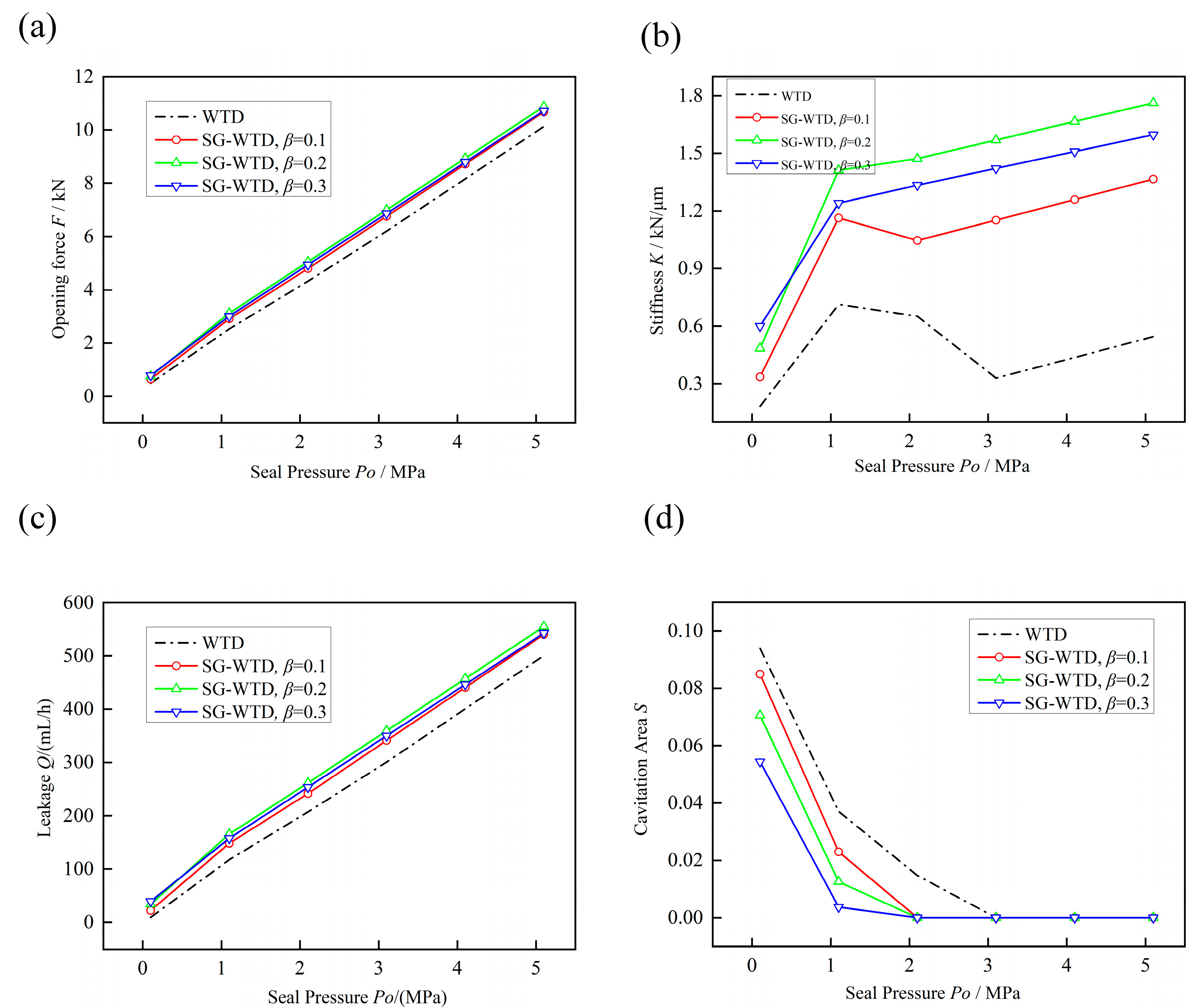
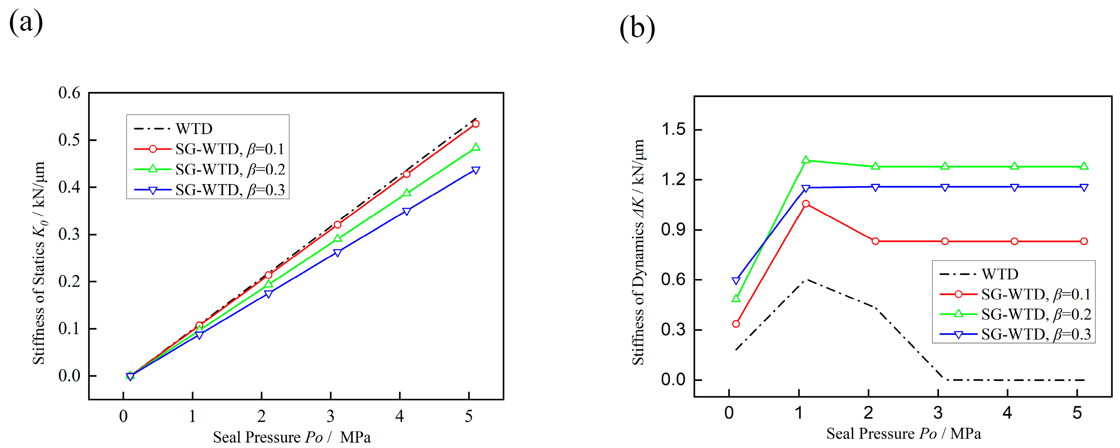
3.2.2. Influence of Seal Pressure
3.3. Influence of Geometric Parameters
3.3.1. Influence of the Shape of Sinusoidal Pattern λ
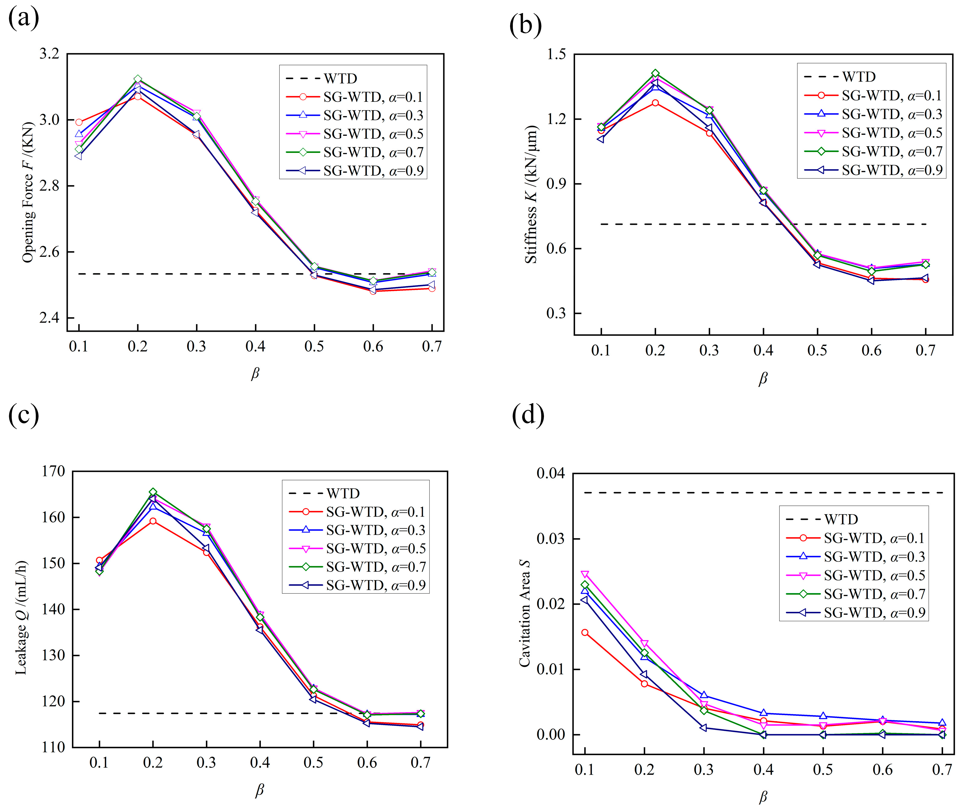
3.3.2. Influence of the Divergence Area Proportion α
4. Conclusions
Author Contributions
Funding
Data Availability Statement
Acknowledgments
Conflicts of Interest
References
- Cheng, H.S.; Castelli, V. Performance Characteristics of Spiral-Groove and Shrouded Reyleigh Step Profiles for High-Speed Non-contacting Gas Seals. Trans. ASME J. Lubr. Technol. 1969, 91, 60–68. [Google Scholar] [CrossRef]
- Wang, Y.M.; Yang, H.Y.; Wang, Y.D. Experimental Investigations and Field Applications of Oil-Film-Lubricated Mechanical Face Seals with Spiral Grooves. Tribol. Trans. 2005, 48, 589–596. [Google Scholar] [CrossRef]
- Wang, Y.M.; Yang, H.Y.; Wang, J.L. Theoretical Analyses and Field Applications of Gas-Film Lubricated Mechanical Face Seals with Herringbone Spiral Grooves. Tribol. Trans. 2009, 52, 800–806. [Google Scholar] [CrossRef]
- Liu, Z.; Liu, Y.; Liu, X.F. Optimization design of main parameters for double spiral grooves face seal. Sci. China Ser. E-Tech. Sci. 2007, 50, 448–453. [Google Scholar] [CrossRef]
- Pennink, H. The Gas Lubricated Spiral Grooved Face Seal in The Process Industry. In Proceedings of the 14th Turbomachinery Symposium, College Station, TX, USA; 1985. [Google Scholar] [CrossRef]
- Galenne, E.; Pierre, D.I. Thermo-elasto-hydro-dynamic modeling of hydrostatic seals in reactor coolant pumps. Tribol. Trans. 2007, 50, 466–476. [Google Scholar] [CrossRef]
- Sato, Y.; Ochiai, M. Temperature Distribution Measurement and Internal Flow Visualization in the Lubrication Film of Non-contacting Mechanical Seals. Tribol. Lett. 2022, 70, 1–14. [Google Scholar] [CrossRef]
- Li, Z.; Li, Y.; Cao, H.; Hao, M.; Liu, F.; Meng, D. Investigation of cavitation evolution and hydrodynamic performances of oil film seal with spiral groove. Tribol. Int. 2021, 157, 106915. [Google Scholar] [CrossRef]
- Iny, E.H. A theory of sealing with radial face seals. Wear 1971, 18, 51–69. [Google Scholar] [CrossRef]
- Liu, Y.; Liu, W.; Li, Y.; Liu, X.; Wang, Y. Mechanism of a wavy-tilt-dam mechanical seal under different working conditions. Tribol. Int. 2015, 90, 43–54. [Google Scholar] [CrossRef]
- Lee, S.; Kim, D.; Park, J.Y. Harmonisation of Coolant Flow Pattern with Wake of Stator Vane to Improve Sealing Effectiveness Using a Wave-Shaped Rim Seal. Energies 2019, 12, 1060. [Google Scholar] [CrossRef]
- Key, B.; Dickau, R.; Carlson, B. Mechanical seals with wavy SiC faces for a severe duty NGL/Crude pipeline application. In Proceedings of the 21st International Pump Users Symposium, Baltimore, MD, USA, 8–11 March 2004. [Google Scholar] [CrossRef]
- Liu, W.; Liu, Y.; Zhai, J.J. Three-Dimensional Flow-Heat Coupling Model of a Wavy-Tilt-Dam Mechanical Seal. Tribol. Trans. 2013, 56, 1146–1155. [Google Scholar] [CrossRef]
- Liu, W.; Liu, Y.; Wang, Y.M. Parametric Study on a Wavy-Tilt-Dam Mechanical Face Seal in Reactor Coolant Pumps. Tribol. Trans. 2011, 54, 878–886. [Google Scholar] [CrossRef]
- Liu, W.; Liu, Y.; Huang, W.F. Effect of disturbances on the dynamic performance of a wavy-tilt-dam mechanical seal. Tribol. Int. 2013, 64, 63–68. [Google Scholar] [CrossRef]
- Yu, H.; Huang, W.; Wang, X. Dimple patterns design for different circumstances. Lubr. Sci. 2013, 25, 67–78. [Google Scholar] [CrossRef]
- Bai, S.; Peng, X.; Li, Y. A hydrodynamic laser surface-textured gas mechanical face seal. Tribol. Lett. 2010, 38, 187–194. [Google Scholar] [CrossRef]
- Reynolds, O. On the theory of lubrication and its application to Mr. Beauchamp Tower’s experiments including an experimental determination of the viscosity of olive oil. Philos. Trans. R. Soc. Lond. 1886, A177, 157–234. [Google Scholar] [CrossRef]
- Laratta, A.; Marzulli, P. Cavitation phenomena in lubricated bearings: Computing method and results. Meccanica 1972, 7, 60. [Google Scholar] [CrossRef]
- Li, J.H.; Liu, X.F.; Huang, W.F. A Finite Element Cavitation Algorithm Using Free Mesh for Mechanical Face Seal. Adv. Mater. Res. 2011, 199–200, 670–677. [Google Scholar] [CrossRef]
- Jang, G.H.; Chang, D.I. Analysis of a hydrodynamic herringbone grooved journal bearing considering cavitation. J. Trib. 2000, 122, 103–109. [Google Scholar] [CrossRef]
- Brewe, D.E.; Jacobson, B.O. The effect of vibration amplitude on vapour cavitation in journal bearings. Wear 1987, 115, 63–73. [Google Scholar] [CrossRef]
- Hajjam, M.; Bonneau, D. A transient finite element cavitation algorithm with application to radial lip seals. Tribol. Int. 2007, 40, 1258–1269. [Google Scholar] [CrossRef]
- Kumar, A.; Booker, J.F. A Mass and Energy Conserving Finite Element Lubrication Algorithm. J. Tribol. 1994, 116, 667–671. [Google Scholar] [CrossRef]
- Grün, J.; Feldmeth, S.; Bauer, F. Multiphase Computational Fluid Dynamics of Rotary Shaft Seals. Lubricants 2022, 10, 347. [Google Scholar] [CrossRef]
- Booker, J.F.; Huebner, K.H. Application of Finite Element Methods to Lubrication: An Engineering Approach. J. Lubr. Technol. Trans. ASME 1972, 94, 313–323. [Google Scholar] [CrossRef]


| Item | Symbol | Dimensions and Data |
|---|---|---|
| Outside radius | ro | 50.1 mm |
| Inside radius | ri | 39.1 mm |
| Dam radius | rd | 41.1 mm |
| Number of periods | n | 9 |
| Tilt | slope | 100 μrad |
| Minimum film thickness | h0 | 2 μm |
| Amplitude coefficient of wave | γ | 1 |
Disclaimer/Publisher’s Note: The statements, opinions and data contained in all publications are solely those of the individual author(s) and contributor(s) and not of MDPI and/or the editor(s). MDPI and/or the editor(s) disclaim responsibility for any injury to people or property resulting from any ideas, methods, instructions or products referred to in the content. |
© 2023 by the authors. Licensee MDPI, Basel, Switzerland. This article is an open access article distributed under the terms and conditions of the Creative Commons Attribution (CC BY) license (https://creativecommons.org/licenses/by/4.0/).
Share and Cite
He, T.; Zhang, Q.; Yan, Y.; Dong, J.; Zhou, P. Numerical Simulation of a New Designed Mechanical Seals with Spiral Groove Structures. Lubricants 2023, 11, 70. https://doi.org/10.3390/lubricants11020070
He T, Zhang Q, Yan Y, Dong J, Zhou P. Numerical Simulation of a New Designed Mechanical Seals with Spiral Groove Structures. Lubricants. 2023; 11(2):70. https://doi.org/10.3390/lubricants11020070
Chicago/Turabian StyleHe, Tao, Qiangqiang Zhang, Ying Yan, Jintong Dong, and Ping Zhou. 2023. "Numerical Simulation of a New Designed Mechanical Seals with Spiral Groove Structures" Lubricants 11, no. 2: 70. https://doi.org/10.3390/lubricants11020070