A Review of Turbine and Compressor Aerodynamic Forces in Turbomachinery


Turbomachinery Laboratory, J. Mike Walker’66 Department of Mechanical Engineering, Texas A&M University, College Station, TX 77843, USA
Lubricants 2023, 11(1), 26; https://doi.org/10.3390/lubricants11010026
Submission received: 13 December 2022
/
Revised: 3 January 2023
/
Accepted: 6 January 2023
/
Published: 10 January 2023
(This article belongs to the Special Issue Fluid–Structure Interaction in Bearings and Seals)
Abstract
:Aerodynamic forces due to blade-tip clearance eccentricity are a known destabilizing source in rotating machinery with unshrouded impellers. Dynamic forces also appear in shrouded impellers, due to changes in the pressure in the gap between the impeller casing and its shroud. These are load-dependent forces typically characterized by a cross-coupled stiffness coefficient (k > 0). This paper reviews the archival literature for quantification of blade-tip clearance induced forces and impeller-casing forces in both unshrouded and shrouded turbines and compressors. Most distinctive are the lack of experimental results and the indiscriminate application of simple formulas to predict k, including Alford’s and Wachel’s equations. The disparity in estimations of the destabilizing k extends to recent CFD models and results. Hence, rotordynamic predictions vary widely. This review reveals that engineering practice ignores accurate physical models that could bridge the gap between practice and theory. As the energy market shifts toward carbon capture and hydrogen compression, accurate knowledge of aerodynamic forces from unshrouded compressors and open impellers will become necessary in multi-stage rotors.
1. Summary
Turbomachinery seals are designed to maintain efficiency and power delivery, by minimizing leakage. Hence, seal design is the most cost-effective practice to increase performance, by restricting secondary flow leakage. High performance turbomachinery operates at large rotor surface speeds (up to 400 m/s), with mechanical components withstanding high temperatures (600 °C and above) and large pressure differentials (21 bar), to produce machines with increased power and efficiency [1]. Seals must be able to control flow, while enduring severe operating conditions; hence, the need for specialized materials and configurations with demonstrated reliable performance, savings in power, and an extended life.
Aerodynamic sources causing forced vibrations in compressors and turbines are well known; for example, the impeller stall, surge, and other flow instabilities created by the gas flow path [2]. Aerodynamic excitations are treated in detail elsewhere. Spakovszky [3] is the latest to review the various physical sources and processes producing the forces driving instabilities, while also stressing that the damping in aero-engines is marginal and difficult to characterize.
This paper reviews the aerodynamic forces due to blade-tip clearance eccentricity in unshrouded (axial) turbines and compressors. A load (torque)-dependent cross-coupled stiffness (k) characterizes the force. For (steam) turbines, this force is known as Thomas’ [4] aero-excitation force (1958), whereas in compressors it is termed as Alford’s [5] force (1965). Practice recognizes that engineers characterize these forces via empirical means. It is important to realize that the aerodynamic (tangential) force in axial compressors destabilizes backward rotor whirl and stabilizes forward rotor whirl motions. Hence, since 1993, k < 0, due to fundamental work conducted by Ehrich [6]. To date, there has only been a handful of crafted measurements verifying the magnitude and direction of tip-clearance excitation forces.
In addition, for shrouded impellers, dynamic forces also appear, due to changes in the dynamic pressure in the gap between the impeller casing and its shroud. These forces are typified as impeller-casing interaction forces and characterized by the full set of force coefficients, i.e., direct stiffness and damping (K, C), as well as cross-coupled stiffness and damping (k, c). Much shop and field operation experience with centrifugal compressors attests to severe rotordynamic instabilities, always inducing forward rotor whirl. In particular, units with shrouds are more prone to subsynchronous rotor whirl; the magnitude of the aerodynamic destabilizing force can be two or more times as large as without blade shrouds. As the rotor vibrates, the secondary flow paths change along the front shroud and back face of the impeller. The same fluid streams also flow through the impeller eye seal and through the inter-stage shaft seal. The secondary flow, displacing radially inward through a shrouded gap, accelerates circumferentially and enters the eye seals with a large swirl velocity. This swirl velocity, often exceeding 50% of the rotor surface speed, generates cross-coupled forces (k > 0) that can induce rotordynamic instability. Seemingly, the stage seals are a destabilizing agent. Inserting a swirl brake upstream of an impeller eye seal or using shunt anti-swirl injection are common methods to stabilize problematic compressors. The same knowledge about the propensity to induce instability and the remedies noted also apply to balance piston seals.
Wachel [7] produced an Alford-like equation for k that includes the gas molecular weight and the ratio of densities (discharge/inlet) throughout the stage. Wachel’s Eq. accounts for both the shroud passages (front and back) and the stage seals. This note also sums the typical rotordynamic analyses, level I and II, required by API (American Petroleum Institute), to predict the margin of system modal damping and the threshold speed of instability.
The analysis of impeller–diffuser interaction forces demands knowledge of the primary flow and must account for the flow through all the passages and stage seals. A bulk flow model [8] (2010) predicts that the impeller eye seal and the inter-stage seal account for 80% and 18% of k, while the front shroud adds just 2.2%. The effect of the back shroud is negligible, even for radial inflow impellers. Alas, recent complex CFD analyses have made evident the importance of the shroud cavity, which generates a significant fraction of the destabilizing force. For example, at one operating point, kCFD = (kseal + kshroud) = (40% + 60%), i.e., the shroud cavity produces 50% more cross-stiffness than the stage seal.
In engineering practice, the Wachel Eq. is applied indiscriminately, and rotordynamic predictions, as expected, vary widely. The present review shows that there are significant differences for the estimation of cross-coupled stiffness (k) as calculated by the various methods, including CFD. The contribution of the shroud cavity to the destabilizing force has not been quantified until recently. To date (2022), there has only been one published experimental evaluation of the static forces in the shrouded impeller of a single-stage compressor. Song et al. [9,10] found that the shroud produces a cross-coupled stiffness that is 2.5 times the k of the eye seal. That is, the shroud contributes 71% of the total k = (kshroud + kseal). Hence, the accepted methods for calculating the cross-coupled (destabilizing) stiffness are way off the experimental results. Prediction from full three-dimensional CFD models will become commonplace in the near future.
2. Introduction
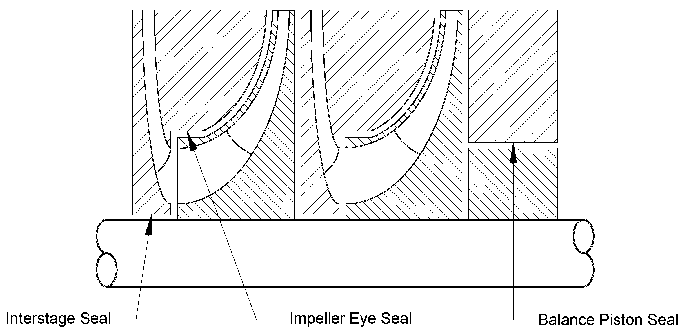
Demand for high-power-density turbomachinery continues to drive the need to accommodate higher pressures and shaft speeds, while ensuring a stable rotor operation with acceptable levels of vibration. Figure 1 depicts the cross-section of a compressor with shrouded impellers and the location of the seals restricting secondary leakage: the impeller eye (or neck ring) and inter-stage seals on each stage, and a balance drum or piston on the right end that reacts to the thrust load produced by each stage.
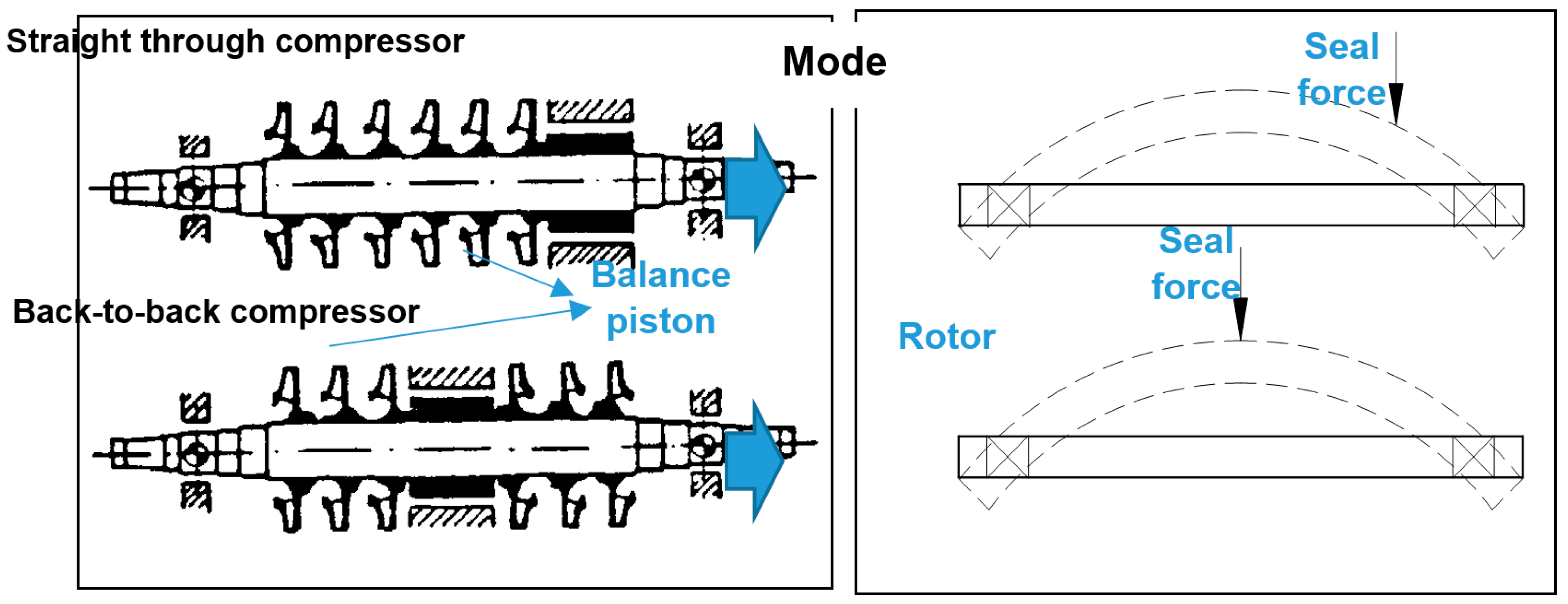
Seals, due to their relative position within the rotor-bearing system, can appreciably affect the system’s dynamic behavior, since these elements are typically located at positions that experience large-amplitude rotor motions. This assertion is of particular importance in back-to-back compressor arrangements [11], see Figure 2.
In 1965, Alford [5] explained two of the probable causes for the self-excited rotor whirl observed in aero-engines. The first refers to a non-uniform circumferential static pressure acting on the rotor surface within seal cavities; and the second is rotor eccentricity causing an unequal circumferential tip blade clearance. The non-uniform circumferential pressure develops a tangential (destabilizing) force proportional to the radial displacement. Alford concluded that a labyrinth seal (LS) having a diverging clearance (knife clearance increases along the flow direction) would be more stable than one with a converging clearance, and with rotor whirl beginning at a torque level proportional to the rotor-bearing system stiffness. Alas, Alford only accounted for axial flow in the analysis and ignored the circumferential flow. The assumption proved incorrect, as later shown by Benckert and Wachter [12], who demonstrated experimentally that the circumferential flow in LSs directly affects their destabilizing forces. Their experiments [12] consisted of statically offsetting a shaft and measuring the cross-coupled stiffness coefficients for LSs (see-through and interlocking), LSs with swirl webs at the entrance plane to disrupt circumferential flow, LSs with swirl webs throughout the seal, and a honeycomb seal. Since their static load test experimental results did not include damping coefficients, the authors recommend a LS with inlet swirl webs (i.e., a swirl brake), over a LS with swirl webs or a honeycomb seal, as the best option to minimize destabilizing forces.
A few years later (1982), while developing turbopumps for the space shuttle main engine (SSME), Von Pragenau [13] showed that a textured (or rough) surface stator, instead of one with a smooth surface, increases the drag and reduces the leakage. The macro-surface roughness also impedes the evolution of the circumferential flow and axial flow velocities. The result is a significant improvement in rotordynamic performance. This improved rotordynamic and leakage performance also applies to compressible fluids, i.e., gases, as verified experimentally by Childs et al. [14,15]. In addition, textured surface seals can produce large direct stiffness (K) and damping (C) coefficients, i.e., centering and dissipative forces that could stabilize an otherwise unstable machine. Incidentally, K < 0 could lead to static instability under particular operating conditions and for seals with distinctive clearance profiles.
In 1997, Childs and Vance [16] reviewed annular gas seals for compressors and turbines and provided details of their effect on the rotordynamics of turbomachinery. At the time, damper seals including honeycomb seals, pocket damper seals (PDS), brush seals, and LS with swirl brakes and shunt injection were in use to improve the stability of rotating machinery equipment, with demonstrated savings in leakage performance. The earlier view that labyrinth seals were bad actors that caused rotordynamic instability problems had changed to considering damper seals as engineered mechanical elements with the ability to improve the rotordynamic response and stability of turbomachinery.
In 2022, San Andrés and Delgado [17] reviewed the experimental record published in the 21st century on gas annular clearance seals, including balance piston seals, and gave an insight into the physical models predicting leakage and dynamic force coefficients. Unlike experiences in the past century, damper seals offer a remarkable opportunity to control the leakage and tailor the rotordynamic performance and stability of modern rotating machinery. This review briefs on the numerical methods, bulk-flow, and CFD available for the prediction of the static and dynamic performance of annular clearance seals.
A Summary of Seal and Stage Reaction Forces and Dynamic Force Coefficients
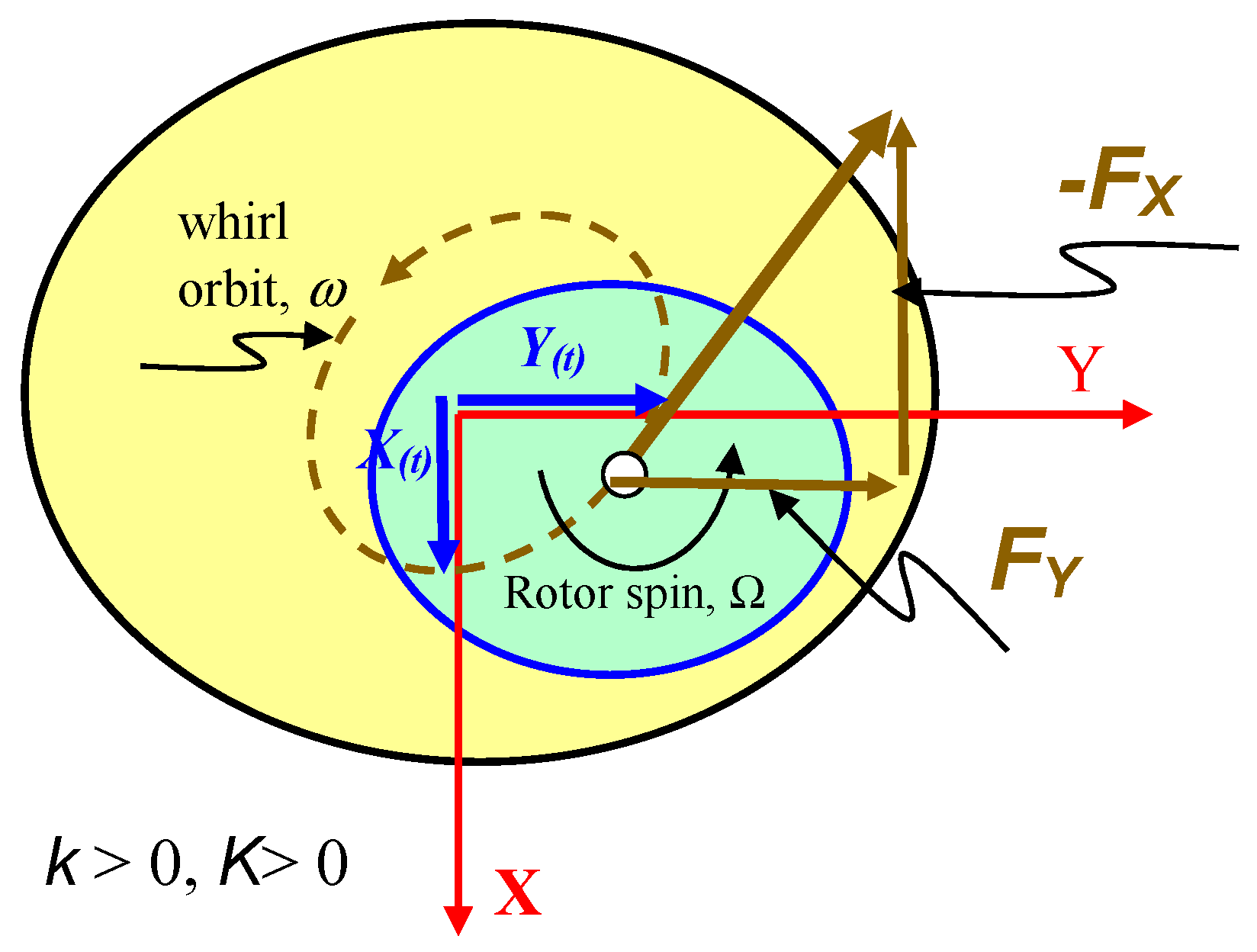
Consider, as depicted in Figure 3, a rotor turning with angular speed Ω and its center displaced with small amplitude whirl motions (X(t), Y(t)) around the center of the seal housing or a stage casing. The rotor motion generates a dynamic pressure field, which produces a reaction force with components (FX, FY). The generally accepted force–rotor displacement model is
Above, (K, k) and (C, c) represent the mechanical element stiffness and damping force coefficients. Until the late 1990s, these coefficients were regarded as constant (frequency independent), a function of the geometry of the flow path and the operating conditions in shaft surface speed (Ω) and the pressure drop (ΔP) across the seal or stage. Note that, in a turbomachine, ΔP is typically a function of shaft speed, i.e., ΔP~Ω2 fluid compressibility, characteristic of gases and supercritical fluids, leads to force coefficients that are functions of the whirl frequency (ω), whilst being modestly affected by the rotor motion amplitude [18].
Considering that the rotor performs circular centered orbits with amplitude r and frequency, then X(t) = r cos(ωt) and Y(t) = r sin(ωt); and Equation (1) becomes
In a moving coordinate system (r, t) turning with the same frequency (ω), the radial and tangential components of the seal (or stage) reaction force equal
are effective stiffness and effective damping coefficients. Note that Keff > 0 produces a centering force as the radial force Fr < 0, whereas Ceff > 0 promotes dynamic stability, since the tangential force Ft < 0 opposes the rotor forward precession whirl. Seal or stage configurations that produce a significant effective damping coefficient are desirable, and those that do not generate a cross-coupled stiffness (k = 0) are best. Note that c(ω) > 0 increases the effective stiffness of the seal or the stage.
The whirl frequency ratio (WFR) is defined as
and the effective damping can be written as
Clearly, as the WFR grows, Ceff decreases. Furthermore, at a certain cross-over frequency
In shrouded compressor stages, a swirl brake (SB) formed by a series of uniformly distributed vanes around its circumference reduces the swirl velocity before its ingress into the seal, hence enhancing the stability of a rotor-bearing system. Balance piston seals often implement swirl brakes (SBs). Not doing so could be deleterious to the stability of the system, as too many incidents attest to costly and often catastrophic failures [19].
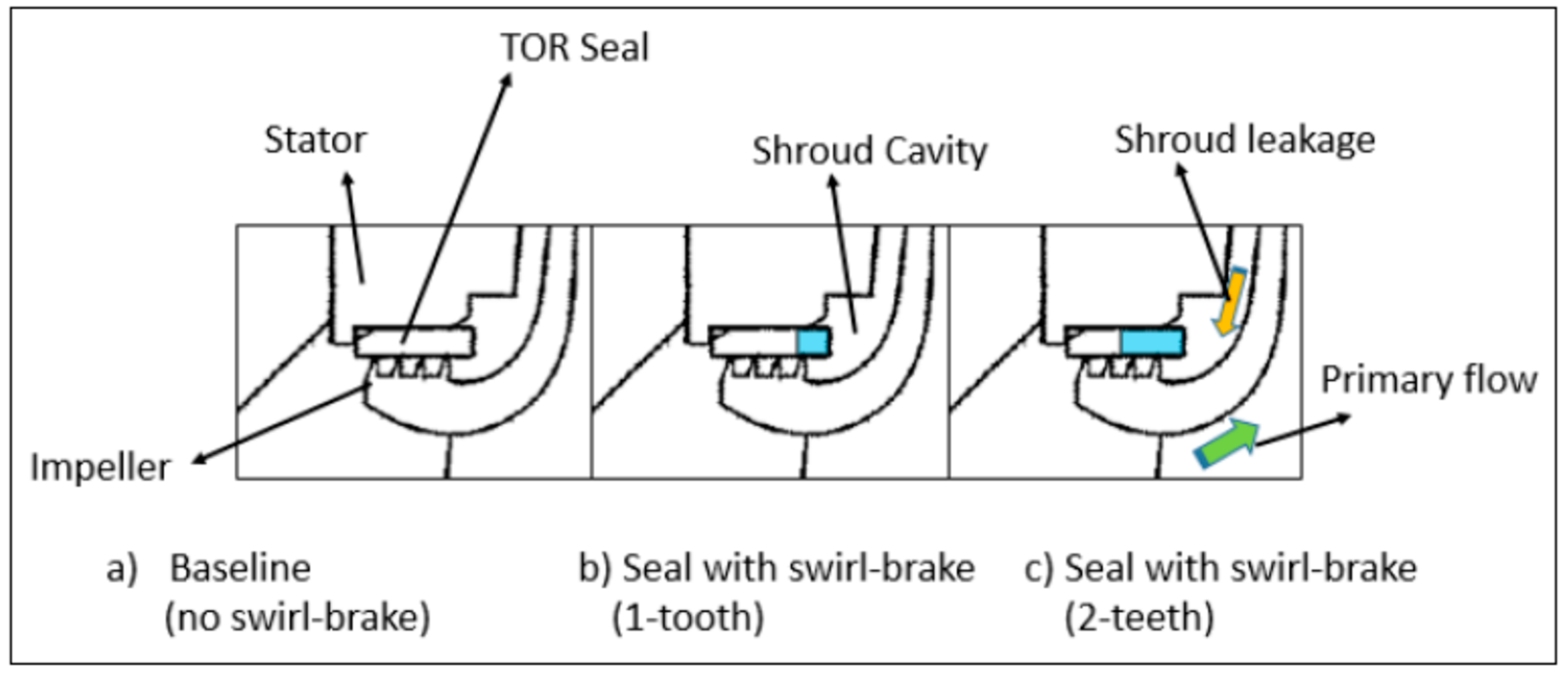
The effectiveness of a SB reduces as the rotor speed increases (above the intended design conditions). In general, SBs do not affect the leakage of the downstream seal element. This last condition may not occur in impeller eye seals, since they are short in a very confined space. The addition of a SB will likely remove one of the knives in the LS, making it less effective in restricting leakage, see Figure 4. On the other hand, a SB at this location, downstream of the impeller discharge, is beneficial to the rotor system dynamics, as proven in the field by Venkataram et al. [20].
3. A Brief Review of Aerodynamic Forces in Turbines and Compressors
Sorokes et al. [2] provided a comprehensive review of the various aerodynamic sources of non-synchronous forced vibration in centrifugal compressors. Their work reviewed the impeller stall, diffuser stall (with and without vanes), compressor surge, and other flow instabilities created by the gas path in the compressor and also a function of the operating conditions and gas composition. More recently, in 2021, Spakovszky [3] presented a magisterial review of the instabilities in aero-engines (some catastrophic), detailing the various physical sources and processes producing the forces driving the unstable phenomena, while acknowledging that, even at this point in time, damping in aero-engines is marginal and hard to characterize.
Aerodynamic forces due to blade-tip clearance eccentricity are a known source mechanism for destabilizing rotating machinery with unshrouded impellers (turbines and compressors). While in operation, a static offset of a turbine or compressor rotor changes the blade-tip clearance and induces non-uniform flow and pressure fields acting on the blades around the rotor. Aerodynamic forces are typically load- and speed-dependent. In addition, for shrouded impellers, dynamic forces also arise due to changes in pressure within the small clearance between the compressor (or turbine) casing and its shroud. Lateral rotor motions induce this type of impeller–shroud excitation force, which can affect the stability of shrouded wheels.
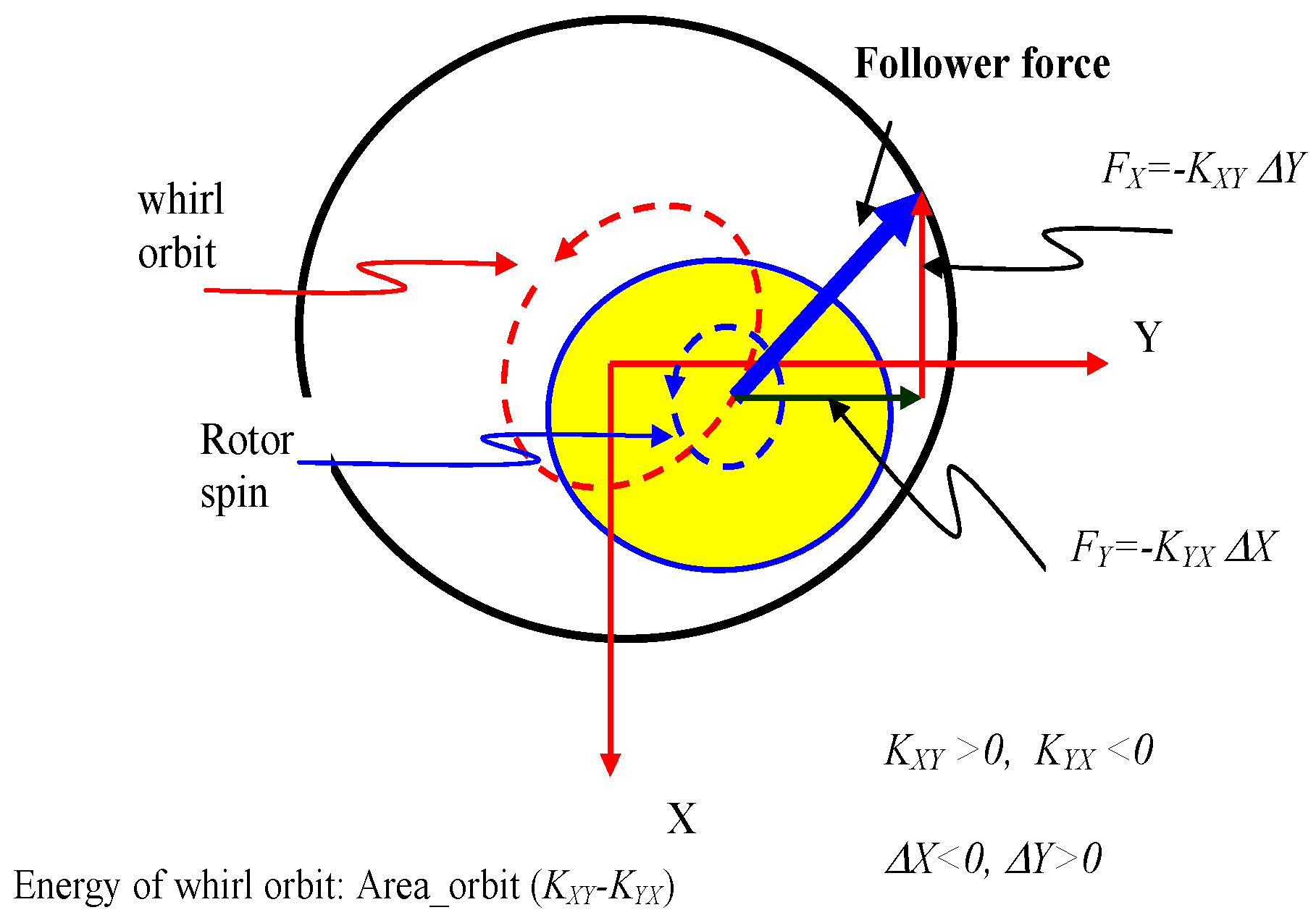
The first type of force is known as the clearance–excitation force, while the latter is typified as an impeller–casing interaction. An aerodynamic destabilizing force is a follower force, driving the rotor into forward whirl motion, as depicted in Figure 5. The components of the force are defined as
where ΔX and ΔY are the rotor lateral displacements and KXY = −KYX = k are the cross-coupled stiffness coefficients. KXY > 0 to induce forward whirl, while KYX < 0 for backward whirl, i.e., opposite to the sense of the shaft rotation.
3.1. Aerodynamic Forces in (Unshrouded) Axial Turbines and Axial Compressors
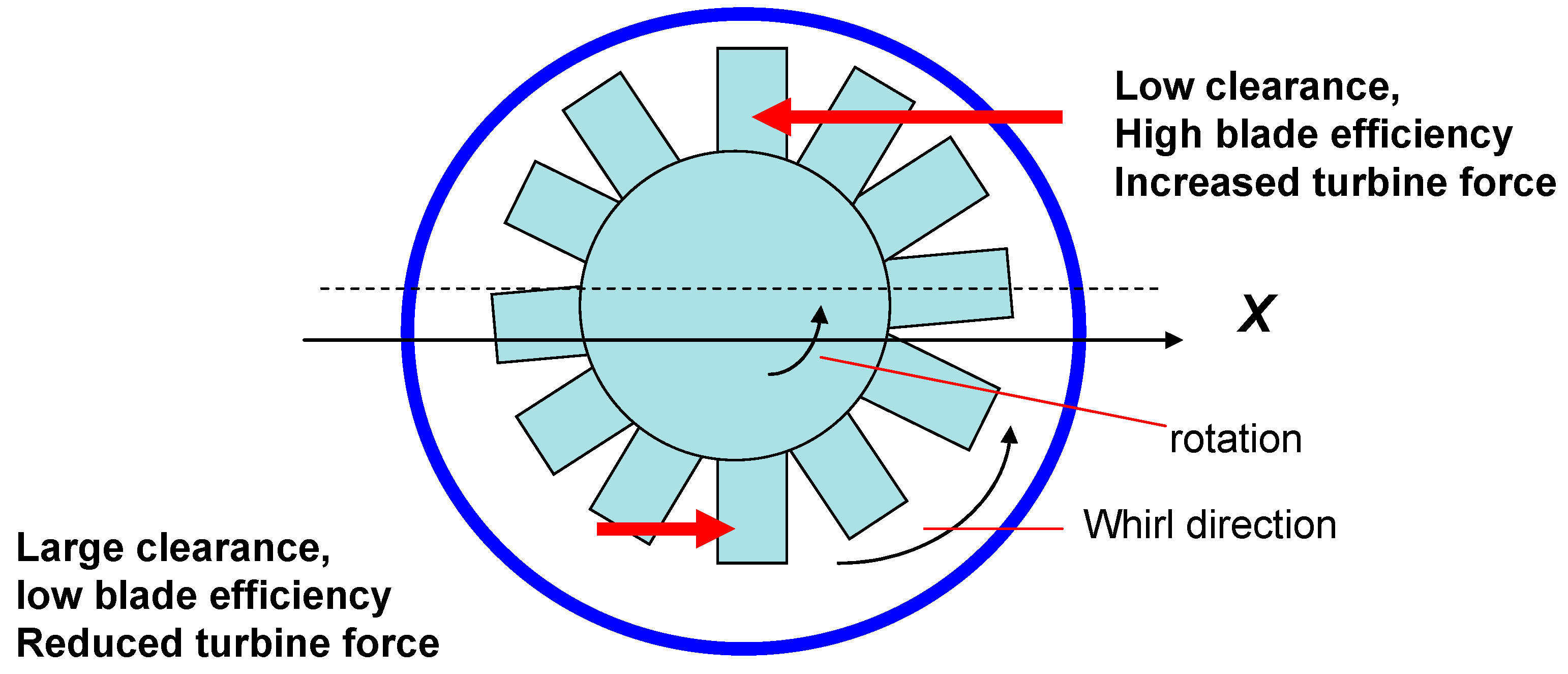
In 1958, Thomas [4] postulated that destabilizing aerodynamic forces in axial (steam) turbines are the result of the non-uniform tip clearance induced by an eccentric rotor, resulting in the whirl of the rotor. In a turbine whose center is eccentric (e), Thomas noted that variations in the clearance cause a change in blade efficiency, i.e., blades with a smaller tip clearance restrict leakage, and the force acting on the blade increases, see Figure 6. The opposite effect occurs in the region of larger local tip clearance. As a result, a net tangential force (Ft) is generated that tends to cause forward (destabilizing) whirl; i.e., in the direction of rotor spinning and with Ft = (k × e). The Thomas “clearance–excitation” force is proportional to the mass flow rate () through the turbine and the enthalpy drop (ΔHD) across a stage, and inversely proportional to shaft speed (Ω). Thus, this force is load-dependent, a function of the applied torque (T0). Recall that mechanical power equals (T0 × Ω)~.
In 1965, Alford [5] advanced a similar model for an axial compressor. Alford reasoned that in a whirling rotor, blades with a smaller tip clearance operate more efficiently and the blades are more lightly loaded than those with a larger clearance. This imbalance of blade forces results in a net follower or tangential force that promotes forward rotor whirl, Ft~(k × e). Alford’s cross-coupled stiffness (k) equals
where To is the compressor stage torque, and D and hB are the mean tip diameter and blade length, respectively. Above, β is “the change of thermodynamic efficiency per unit of rotor displacement, expressed as fraction of blade height.” Alford recommended β ranging from 1.0 to 1.50. Most importantly, as argued by Alford, the aerodynamic force is forward (direction of shaft rotation) for both compressors and turbines. Hence, in Alford’s theory, there is no distinction between the physical operation of both types of machines.
For an axial turbine (unshrouded) stage, the experimental results from Urlichs [22] verified Thomas’ clearance–excitation force model. Conducted with blades whose tips had variable axial and radial tip clearances, the measurements recorded both a tangential force and a radial force, as a function of the static rotor offset relative to its casing. In the measurements, the radial force was not a centering force and was a sizeable fraction of the tangential force. Later, in 2005, Kanki and Tanitsuji [23] presented experimental results demonstrating that a turbine, operating under partial admission, has a larger destabilizing aerodynamic force that is greatly affected by the pattern of partial admission. Note that Alford’s Equation (9) is not explicitly a function of the tip clearance, whereas measurements demonstrate that enlarged clearances determine smaller forces (and less efficient stages); see the work of Ehrich [6]. In addition, the model in Equation (9) fails to quantify the (measured) centering force with direct stiffness K.
In 1984, Vance and Laudadio [24] conducted measurements of aerodynamic forces in a small, high-speed, axial-flow fan with a moveable casing, to control the rotor offset. In the tests, the rotor deflection and speed and drive torque were measured. In spite of the poor test repeatability (typically ±20% for two successive measurements), the test data showed that Alford’s force is a function of speed as well as of torque. The aerodynamic force inducing forward whirl did not appear until a certain torque threshold was achieved. However, under specific test conditions, the aerodynamic force became negative; i.e., driving backward whirl (k < 0).
In his textbook (1992), Ehrich [21] advanced the argument above and questioned Alford’s physical arguments. Normalization of the test data from Vance and Laudadio [24] showed that Alford’s force varied linearly with torque, as predicted, but evidencing a positive magnitude above a certain threshold torque. The magnitude of the tangential force increases as the shaft speed increases. Below the threshold torque, the force is negative and drives the backward whirl of the test rotor.
Based on the actuator disc model of Horlock and Greitzer [25] (1983), Colding-Jorgensen [26] (1992) introduced an analysis to determine the direction of the aerodynamic force in axial unshrouded compressors. The predictions showed that forward whirl prevails over the normal operating range of a compressor, although backward whirl can be present for extremely low flow rates (i.e., stall conditions). The predicted β was ~2.0, a typical value assumed for compressors.
For axial compressors, the correct sign (positive or negative) of the aerodynamic force was a major unknown. Not until 1993 did Ehrich [6] demonstrate that the aerodynamic (tangential) force in axial compressors destabilizes backward rotor whirl and stabilizes forward rotor whirl motions. That is k < 0! Later in 2001, a comprehensive experimental effort [27,28] endorsed Ehrich’s assertion. Ehrich argued that since (axial) compressor blades with smaller tip clearances operate more efficiently, they are subject to a higher static pressure difference across their tips and are, in fact, more highly loaded than blades with a larger tip clearance (opposite to Alford’s argument). Hence, in an axial flow compressor, the net tangential force direction promotes backward rotor whirl.
Litang et al. [29] (1994) conducted strain gauges measurements on a single stage axial compressor, to determine the direction of Alford’s force. The experimental results showed that Alford’s force acts in a direction opposite to the shaft rotation, thus promoting backward whirl. In addition, the non-uniformly distributed dynamic pressure around the compressor also generates a radial force component that acts in the direction opposite to rotor eccentricity, i.e., a centering stiffness (K > 0).
In the late 1990s, Storace et al. [27] and Ehrich et al. [28] (2000), at the GE Low Speed Research Compressor Facility, conducted a large-scale research effort to resolve the apparent disparity in findings, by definitively determining the direction of whirl caused by Alford’s force in axial compressors. The test program used an axial flow compressor with several distinct blade configurations, although only one configuration with a static rotor offset (eccentricity). The measurements showed that β < 0 over most of the compressor operating speed range, with some near-zero and small positive values occurring at high flow rates near the design point. The authors, based on their definitive measurements, stressed that backward-whirl-inducing forces are present in axial flow compressors. Incidentally, measurements of blade loading showed that blades with a smaller tip clearance are more highly loaded than those with a larger tip clearance; hence, validating Ehrich’s model of compressor whirl forces.
Implementing a “parallel compressor” model and using the data collected at the GE Low Speed Research Compressor facility (a four stage compressor and two tip clearances), Ehrich et al. [28] reported β ranging from +0.27 (forward whirl) to −0.71 (backward whirl) along a normal operating line; β~0.08 to −1.21 in the vicinity of blade peak efficiency; and β < 0 (−1.16 to −3.36) near the compressor stall condition. In their experiments, backward rotor whirl appeared over much of the compressor’s normal operating range, with strong backward rotor whirl near stall operating conditions.
In 2000, Spakovszky [30] and Song and Cho [31] developed computational physical models to more accurately predict β. Spakovszky introduced an additional parameter (βspool), known as the blade loading indicator, that denotes the effect of a non-axisymmetric pressure distribution on the rotor spool. This effect, first identified by Song and Martinez-Sanchez [32] (1997), induces an additional tangential force in turbines and is suspected to play a role in compressors as well. Under a steady shaft offset displacement (eccentricity), Spakovszky predicted a strong tendency towards backward whirl for operation at low flow coefficients, whereas forward whirl appears for high flow coefficients. These findings are in agreement with Ehrich’s measurements [6] (1993). Spakovszky found βspool > 0 over most of the compressor operating range, i.e., inducing forward whirl, though its magnitude is typically ~50% of Alford’s β parameter. However, under forced whirling conditions, βspool is comparable in magnitude to Alford’s β, but acting in the direction opposite of the whirl. The blade loading indicator (βspool), a function of the stage geometry and mean flow, determines the direction of whirl due to tangential blade loading forces.
The model by Song and Cho [31] also includes the effect of a non-axisymmetric pressure distribution and predicts the velocity and pressure fields induced by tip clearance asymmetry. Torque asymmetry determines a negative cross-coupled force, i.e., promoting backward whirl, while pressure asymmetry brings a larger positive cross force (k > 0). Thus, the end effect induces a forward whirl force in axial turbines. The analysis also revealed a positive radial force, mainly due to pressure asymmetry. In a follow up paper, Song and Park [33] (2001) presented a novel actuator–disk model to analyze flow redistribution as a result of rotor-tip clearance in axial compressors. Their predictions showed that the cross-coupled force is negative, thus promoting backward whirl. In brief, the tangential force induced by a negative (drag) torque is slightly larger than the positive force originating from pressure asymmetry.
In 2003, Al-Nahwi et al. [34] presented a first principles-based model of the fluid-induced forces acting on an axial compressor and combined it with the Moore–Greitzer model [35] of an axial compressor flow field. Myllerup and Keith [36] (2004) [24] further advanced the model by Al-Nahwi et al. for ready use in a rotordynamics predictive program. The model identifies three contributions to the overall value of the cross-coupled (tangential) aerodynamic force: nonuniform torque, nonuniform hydrostatic pressure, and unsteady momentum storage within the rotor blade passages. These three contributions are represented by four terms in the model: one torque term, two pressure terms, and one unsteady momentum term. The model shows that, since the terms may all be of comparable magnitude, all of the force contributions must be taken into account to accurately predict the whirl direction of the aerodynamic force. Thus, aerodynamic forces can induce forward or backward whirl, depending on the operating conditions of the compressor, namely the flow rate and whirl frequency.
Based on a review of the published experimental data to 2013, Childs [19] noted that shrouded turbines are more prone to subsynchronous whirl destabilizing forces than those without shrouds. That is, the magnitude of the aerodynamic destabilizing force can be two or more times as large as without blade shrouds. Apparently, stage seals are a destabilizing agent. Childs recommended the implementation of upstream swirl brakes (SBs) to reduce the inlet swirl velocity into stage seals; see Venkataraman et al. [20] for an application in an unstable compressor that became stable after inserting Sbs upstream of the neck-ring stage labyrinth seals.
Most measurements conducted with axial compressors show aerodynamic forces inducing backward whirl over most of the operating range in axial compressors; forward whirl only occurs at high flow rates. In contrast, early numerical models (1990s), such as those from Alford [5] and Colding-Jorgensen [26], gave conflicting results, suggesting only forward whirl. However, more advanced models, in particular that of Myllerup and Keith [36] stressed that there are other contributions to the aerodynamic force. In particular, the non-axisymmetric pressure distribution on the blades and the unsteady momentum storage within blade passages must be accounted for, to accurately predict the magnitude of the force and its direction of whirl. A compressor may display forward or backward whirl, depending on the operating conditions and compressor geometry. Importantly, in gas turbines for aircraft or power generation, the effect of the aerodynamic force from the turbine is more important than that of the compressor, due to the vast differences in power (torque).
As Spakovszky emphasized recently [3] (2021), aerodynamic forces can induce either forward or backward whirl, depending on the operating conditions of the compressor or turbine, namely the flow rate and whirl frequency, as well as the stage geometry. One must also stress that, to date (2022), rotordynamic engineers in the O&G industry have indiscriminately applied Alford’s Eq., rather than results from more advanced analytical models [30,31,36] and those based on computational fluid mechanics [37,38] published since 2018. These latter models predict both radial and tangential forces, i.e., direct and cross-coupled stiffnesses (K, k), and provide comparisons with the experimental data of Ulrichs [22] and the blade geometry given in Ref. [39]. These recent papers produce more complex models that account for rotor eccentricity and blade tip clearance.
3.2. Destabilizing Forces in (Shrouded and Unshrouded) Centrifugal Compressors
As demonstrated by Ehrich [6] in 1993, Alford’s argument for the direction (forward whirl) of the aerodynamic force in compressors is incorrect. Nonetheless, Childs [11,19] stresses that shop and field operational experience with centrifugal compressors attests to severe rotordynamic instabilities, always inducing forward rotor whirl. In particular, units with shrouds are more prone to subsynchronous rotor whirl than those without shrouds. The magnitude of the destabilizing force can be two or more times larger [40] than the force induced by an open impeller, i.e., one without a shroud. The source and magnitude of the destabilizing force has promoted much discussion and research.
With reference to Figure 1, as the rotor vibrates, the impeller moves and open/closes the secondary flow paths along the front shroud and back face of the impeller. The same fluid streams also flow through the impeller eye (or neck-ring) seal and through the inter stage shaft seal. The secondary flow, displacing radially inward through a shrouded gap, accelerates circumferentially and enters the neck ring seals with a large swirl, whose mean circumferential velocity exceeds 50% of the rotor surface speed. The large swirl generates large cross-coupled forces (k > 0) that can induce a rotordynamic instability. This force is generally known as the rotor–impeller shroud interaction force, to distinguish it from the tip clearance excitation forces that are typical in axial compressors and turbines.
Childs [19] notes that impeller–rotor interaction forces increase sharply (k >> 0) with the decreasing clearance between the impeller shroud and the pump housing. Ehrich [21] also argues that enlarged clearances in the exit (eye) seal due to rubbing, wear, or damage increase the (mean) circumferential flow velocity through the shroud, entering into the seal and thus increasing the cross-coupled forces.
Experimental data are scarce! Moreover, there has been no definitive analysis on impeller–rotor interaction forces applied to centrifugal pumps and compressor stages. For liquid pumps, predictive analysis relies on a handful of experimental results conducted at Cal Tech [41] (1982) and Sulzer [42] (1987), see inset graph taken from Childs’ textbook (Figure 7) [11].
To date, the most important question has been to pinpoint the exact source of the dynamic reaction forces (or moments). The impeller–rotor interaction force combines the contributions of dynamic forces arising from the front and back faces of the impeller, as well as those arising from the neck-ring (eye) seal and inter-stage seals.
Impeller lateral forces are typically modeled as (Childs [11]):
This reduced model force representation assumes rotational symmetry and circular centered whirl motions. Experimental results are typically presented in dimensionless form as
with Ω as the rotor speed and mref as a reference fluid mass (density x volume of solid disk with tip diameter Do and thickness b2). For m~0, the whirl frequency ratio, WFR = k/(CΩ), relates the whirl frequency of unstable motions to shaft speed. A WFR = 0.5 means that the compressor cannot stably operate at a shaft speed above two times (=1/WFR) the system first natural frequency.
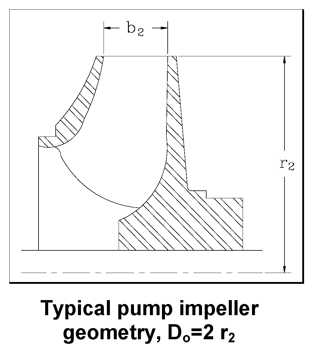
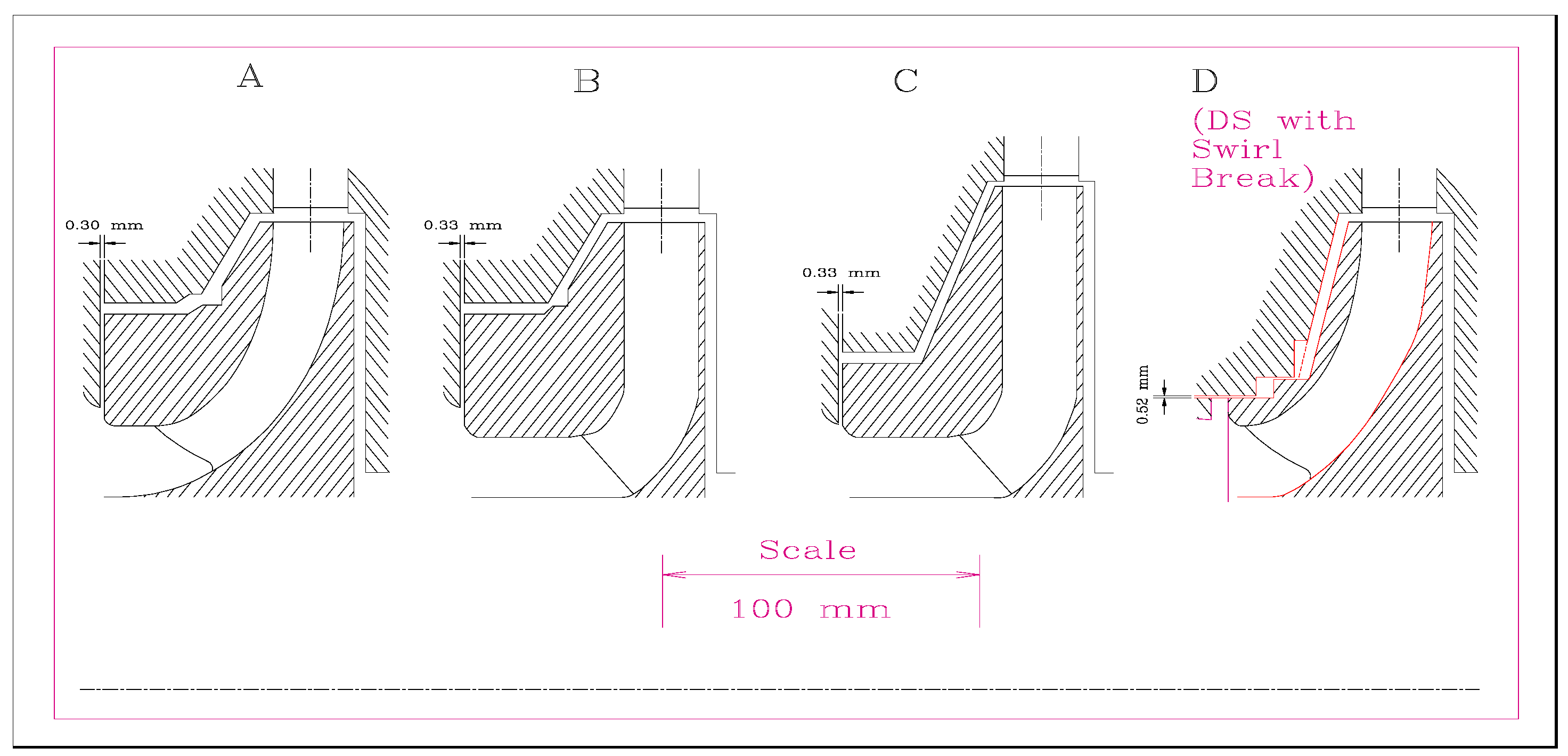
Figure 8 displays the four pump impellers tested at Sulzer [42], and Table 1 lists the dimensionless force coefficients obtained from the experiments. These tests are of particular importance, since the clearance between the impeller shroud and casing was small, Cr = 0.067 mm to 0.081 mm, representative of actual applications.
From the experimental results, see Table 1, the following conclusions can be derived:
- Impellers have negative direct stiffness and large direct and cross-coupled inertia coefficients.
- The cross coupled stiffnesses are much larger for tight clearance impellers, thus generating large destabilizing forces at rotor speeds below the rotor-bearing system critical speed, i.e., WFRs > 1.
- The shroud generates most of the destabilizing forces in a pump impeller.
- Enlarged clearances in neck ring seals aggravate the generation of cross-coupled forces, since the swirl flow into the seal increases. Enlarged clearances are the result of transient rubbing events in the operation of a pump.
- At reduced flow rates (<QBEP), the impeller cross-coupled stiffnesses are smaller.
- Impeller–volute interaction forces are small and benign.
- In a radial flow impeller, the cross-coupled stiffnesses are small, i.e., the destabilizing force is negligible, since the projected axial area of the shroud is quite small.
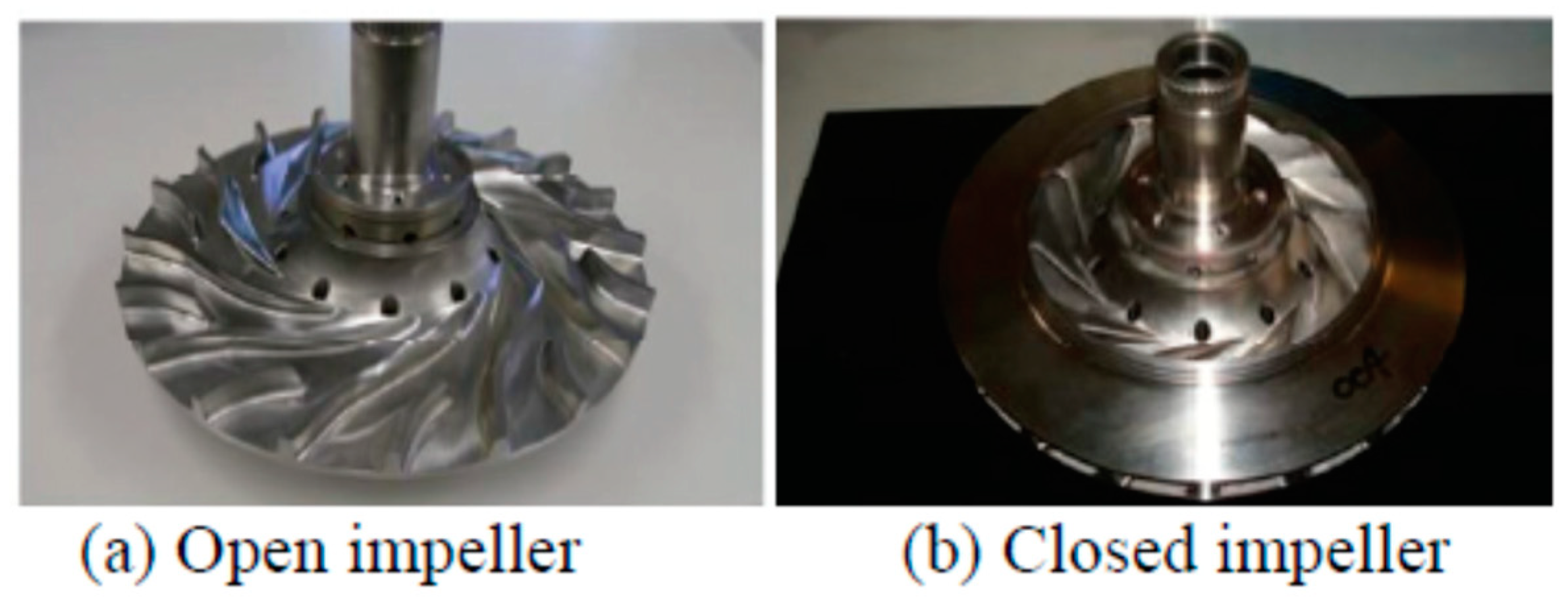
In 2012, Uchiami et al. [43] presented the results of an extensive R&D program testing open and closed impellers for a cryogenic fluid turbopump, see Figure 9 The test fluid was water, and the excitation frequency reached up to 1.5 times the shaft speed (max 1200 rpm [30 Hz]). The measured forces (radial and tangential) for the impeller were small compared to those of the closed impeller. The open impeller produced a positive centering stiffness (K > 0) and added mass (M > 0) coefficients, while the closed impeller showed K < 0 and a lower M < 0. As per the damping coefficients, the open impeller had direct and cross-coupled damping coefficients C, c > 0, whereas the closed face impeller produced c > C > 0. Both impeller types produced a cross-stiffness of similar magnitude; hence, the open impeller offered a larger speed stability range than the one with a shroud.
Recently (2021), Jolly et al. [44] compared the force coefficients obtained from a pump impeller with an open face (unshrouded) with another with a closed end (front shroud). Both units had a vaned diffuser. The intended application uses a cryogenic liquid, whereas the tests were conducted with water and at a fraction of the rotor speed and pressure rise that a typical aerospace turbopump would see. The closed impeller configuration had an eye packing seal with one of three configurations: a smooth surface annular seal, a labyrinth seal, and a face seal. The front casing of the shrouded impeller was either a smooth surface or a textured one. Rotor speed reached 5 krpm, and water was supplied at 6 bar. The experimental results showed that the open impeller produced force coefficients with a lesser magnitude than the closed faces impellers; in particular, the direct stiffness for the closed impeller with annular seal was positive, whilst that for the open impeller was negative. The direct damping coefficients were insensitive to rotor speed with the closed impeller, having an annular seal producing the largest magnitude; typically twice as large as the coefficient for the open impeller. Cross-coupled stiffnesses and damping coefficients were similar in magnitude for all configurations, open and closed, and decreased as the rotor speed increased. The rather short paper does not give details on stability, albeit one can infer a WFR = (KC/ΩCD) > 1 for low shaft speeds (<2 krpm), and WFR→0.5 at the highest speed (5 krpm) for the closed impeller, whilst for the open impeller WFR > 4 at low speed and WFR→1 at the highest speed.
Yoshida et al. [45] (1999) presented the only rotordynamic force measurements conducted with an unshrouded 12 blade centrifugal compressor, albeit operating with water to amplify the magnitude of the aerodynamic forces. The impeller operated inside a vaneless diffuser and with an axisymmetric discharge collector to minimize the interactions with stationary parts. In the experiments, conducted for increasing whirl ratios (ω/Ω) with orbit radius at 60% of the clearance and increasing flow rates, aerodynamic forces were recorded using four-axis load sensors and also by integrating casing pressures. The tests showed destabilizing forces at a small positive whirl speed ratio (0 < ω/Ω < 0.3) throughout the flow range of normal operation. At small flow rates (Φ~0.285) with inlet backflow, the magnitude of the fluid force changed suddenly at a whirl speed ratio ω/Ω~0.8, resulting in even larger destabilizing rotordynamic forces. The test data showed that the radial and tangential forces did not fit the (linearized) rotordynamics force model in Equation (10).
In the cited reference [45], the forces estimated from the pressure difference across the impeller blades did not agree with the direct measurements of force, and hence the authors noted that the destabilizing force was not just due to tip-clearance variations that changed the blade loading, but also due to a nonuniform pressure distribution acting on the blades. The analyses of Al-Nahwi et al. [34] and Myllerup and Keith [36] fully endorsed the rationale derived from the experimental data.
Table 2 lists the dimensionless test force coefficients obtained by Yoshida et al. for the compressor operating at its design flow rate. A comparison with the pump–impeller test data, see Table 1 in particular the row labeled as CT-volute, shows that the compressor developed similar levels of cross-coupled stiffness (=1.10pump) and direct damping (=3.14pump) and a nearly identical whirl frequency ratio (WFR~0.35pump). The pump, on the other hand, evidenced large cross-coupled damping ~7.91pump and cross-coupled inertia ~−0.58pump. The most important difference relates to the compressor developing a positive direct stiffness = 1.25, while = −2.5pump.
To date, there have been no other comprehensive experimental programs conducted with centrifugal compressors, shrouded or unshrouded, and aiming to measure rotordynamic force coefficients and determine their stability characteristics.
3.3. Wachel’s Equation and Its Effect on Compressor Stability
Returning to the basic query of this section, there has been much experience with closed face (shrouded) centrifugal compressors (and turbo expanders) becoming rotordynamically unstable, always with forward whirl. Since the mid 1980s’, the Proceedings of the Turbomachinery Symposium have hosted many lectures and case studies showcasing these often costly instabilities, along with remedies to fix or resolve the issue. An exhaustive list of the mentioned papers is outside the scope of the current review.
Developed for shrouded compressors, Wachel’s Eq. (1981) below is routinely used for prediction of a destabilizing cross-coupled stiffness coefficient (k > 0) [46,47].
where To is the torque = (compressor power/shaft angular speed), D is the impeller tip diameter, and hW is the diffuser width. Above MW is the gas molecular weight, and (ρout/ρin) is the ratio of gas densities discharged over the inlet. The parameter β ranges from 2 to 5 for most high performance compressors. Note that Wachel’s equation, derived from correlation studies of field experiences with unstable compressors, is in actuality a modified form of Alford’s force model, as explained by Evans and Fulton [7]. The ratio (MW/10) appears arbitrary, and API [48] sets MW = 30 for hydrocarbon gas processing compressors. The API formula is known as the PACC #, i.e., the predicted aerodynamic cross-coupling number.
Routine rotordynamic analyses for shrouded wheels of centrifugal compressors implement Equation (12), with additional correction factors known to the manufacturer and based on experience. For example Dresser-Rand [49] (currently Siemens Energy) multiply Equation (12) × 0.80 and call it the Modified PACC number (MPACC).
In 2005, Nicholas and Kocur [50] and Li et al. [51] argued there is a long-standing confusion regarding the application of Wachel’s formula to predict destabilizing forces and their ultimate impact on the stability of (shrouded) centrifugal compressors. Gas densities in Wachel’s formula, Equation (12), can relate to either the inlet and exit conditions in a single stage or the entire compressor train, for example. Furthermore, when assuming a single Wachel’s force to represent the entire machine, an open question is its actual (physical) location in the compressor train. The references try to make sense of API 617 requirements, albeit applying ad hoc procedures that integrate indiscriminately both labyrinth seal forces and Wachel’s formula.
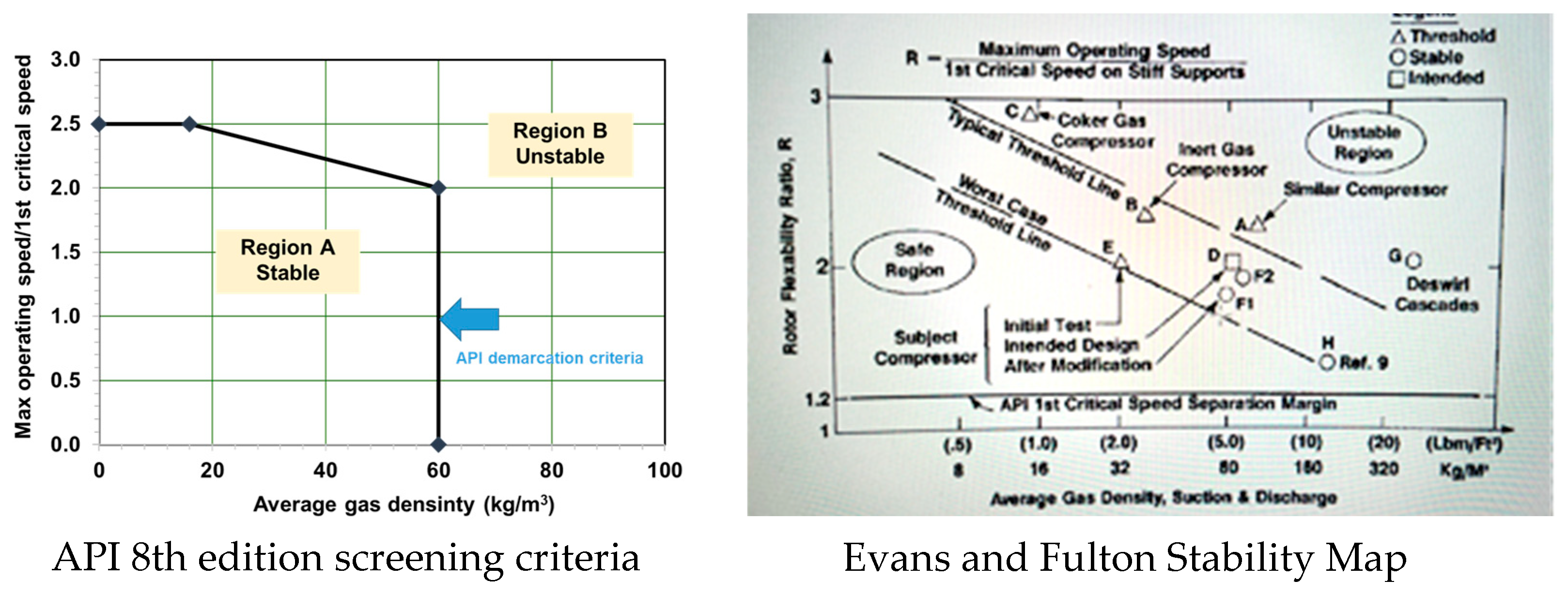
In 2010, Evans and Fulton [7] provided a more useful insight into the origin of Wachel’s formula and fully explained its various forms, as applied to a rotordynamic analysis. The authors also elaborated the (so-called) Fulton–Sood stability map shown in Figure 10. The map contains an informative collection of stable and unstable compressors defined by the ratio of operating speed/critical speed (>2.5) vs. average gas density (from suction and discharge). The authors stressed that Wachel’s formula estimates the force from the shroud cavity (front and back) and includes the seals, eye, and inter-stage. That is, Wachel’s equation applies to a whole stage and not to its various flow paths and elements.
In practice, engineering process calls for varying the cross-coupled stiffness (k), to predict the margin of system modal damping and the threshold speed of instability in consideration of API 617 [48] specifications, as per level I and level II analyses. This is a sensitivity analysis that focuses on quantifying the stability, or lack thereof, of the first forward damped mode with a frequency greater than the first undamped critical speed on rigid supports. The API norm makes a distinction between rotors fully supported on two bearings, overhung rotors, and double overhung rotors.
A level I analysis uses Wachel’s equation to approximate the destabilizing effect of the labyrinth seals and (any other) aerodynamic excitation (namely the impeller secondary flow paths) from each impeller and adds to a total anticipated . The overall anticipated cross-stiffness (Q) is varied to a maximum of 10 QA or until the log-dec δA = 0 obtained for an overall cross-coupled coefficient with magnitude Qo.
If the compressor fails the Level I specification, then a more sophisticated Level II analysis is required. Failing level I means predicting either δA < 0.1, or Qo/QA < 2, or Qo/QA < 10, and the location in region B of the point is defined by the intersection of the critical speed ratio CSR (operating speed/undamped natural frequency) and the average density at the normal operating condition, see Figure 9. The Level II analysis accounts for forces from all stages, including their labyrinth seals, damper seals, impeller/blade flow aerodynamic effects, and internal friction.
Published in 2022, the API 617 9th edition [52] offers more insight (and details) into the screening criteria for level I analysis, with force coefficients for labyrinth seals calculated at the minimum and maximum seals’ operating clearances and using the operating clearance for damper seals, including any mechanical deformation. For double overhung machines, the norm explicitly calls for a stability quantification (log-dec estimation) of the first two forward modes.
Gupta and Childs [8] emphatically note that Wachel’s formula, though based on certain empirical evidence, is neither supported by sound physical arguments, nor by analysis. The analysis of impeller–diffuser interaction forces should include the flows and dynamic pressures generated on the curved path in front of the shroud and on the back face of the impeller. Most importantly, the analysis must account for the sealing elements (labyrinth typically): neck ring or eye seal and inter stage seal, where large pressure gradients occur and are greatly influenced by the inlet fluid rotation or swirl condition. In Gupta and Childs analysis, the eye seal and the inter-stage seals account for 80% and 18% of the cross-coupled stiffness (k), while the front shroud contributes just 2.2%. The effect of the back shroud is negligible, even for radial inflow impellers.
Since the early 2000s, Moore and co-workers at Southwest Research Institute have conducted CFD studies of centrifugal compressors and radial turbines (unshrouded single stage), to predict the aerodynamic destabilizing forces; see Refs. [53,54]. Moore and Ransom [55,56] have presented an alternative to Wachel’s equation, namely
where the dynamic head at the exit plane of a compressor replaces the drive torque, U is the wheel tip speed, Lshroud is the axial length of the shroud, and (Q/Qdesign) is the flow relative to the design condition. Cmr, a constant for a given impeller design, ranges from 4.0 to 7.5 (when using SI units). If Equation (13) is to be applied to a turbine or a turbo expander, take the inlet plane as the reference for dynamic head.
In Lerche et al. [53], for the particularly unstable turbo expander analyzed, the cross coupled stiffness (k) predicted by various models differed significantly. The unit processed a refrigerant gas whose large MW = 104 played a significant role in amplifying the unstable force. Using Alford’s Equation (9) with β = 1.5, then kAlford = 6355 N/m; whereas Wachel’s Equation (12) produces kWachel = 11.13 kAlford, and using API’s formula with MW = 30 predicts kAPI = 3.27 kAlford. Similarly, using Moore and Ransom’s Equation (13) gives kMoore-Ransom = 1.71 kAlford, while the prediction from an unsteady CFD study of the forces produced by the expander delivers kCFD = 2.32 kAlford.
CFD analyses continue to evolve as computational resources are more readily available, along with faster speeds of execution. High fidelity 3D CFD models, constructed with many millions of nodes or cells, include both the main flow path and the secondary (leakage) flow paths in the front and back shrouds and through the seals. Transient or periodic shaft motions, along with deformable meshes predict the unsteady flow and pressure fields acting on the impeller surfaces to produce forces, from which the force coefficients are extracted.
These examples of CFD analysis have made palpable the importance of the shroud cavity in generating a significant fraction of the destabilizing force. Zhang et al. [57] reported force coefficients in the front shroud cavity and eye seal of a stage in a centrifugal compressor. At one operating design condition, kCFD = (kLS + kshroud) = (40% + 60%), i.e., the shroud cavity produced 50% more cross-stiffness than the eye seal. Predictions showed that the total k (>K) grew with the power two of the shaft speed. Later, Hoopes et al. [58] reported, at one operating condition, kCFD = 2.99 MN/m = (kLS + kshroud) = (34 % + 66%) = 1.53 kWachel = 2.35 kMoore-Ransom. The authors noted the generation of a non-uniform circumferential pressure field regulated by the LS varying clearance as the impeller whirled.
In 2021, Kim and Venkataraman [59] modeled a multiple-stage compressor that was rotor-dynamically unstable in the field, and where installation of swirl brakes (SB) upstream of the eye seals fixed the issue, see Ref. [20]. For the baseline condition, before SB installation, at the 2nd stage of the compressor, kWachel = 439 kN/m, kAPI = 1.07 kWachel, kMoore-Ransom = 0.935 kWatchel, and kCFD = 1.245 kWatchel. Similarly, for the 5th stage, kWachel = 424 kN/m, and kAPI = 1.07 kWachel, kMoore-Ransom = 1.127 kWatchel, whereas kCFD = 1.917 kWatchel. The CFD cross-coupled stiffnesses (k’s) were larger, since they accounted for the asymmetric pressure field in the shroud that also exerted a force on the impeller. Note again the wide variation in predictions depending on the model used. The same reference produced a table (see below) that separated the individual contributions of the eye seal and shroud to the force coefficients, k and C. The tabulated results made evident the benefits of the SB upstream of the LS. Note that, for the baseline condition (one without SBs), the eye seal contributed 57% of the total k. On the other hand, for the stage with the installed SB, the total k magnitude was much lower (~38% of baseline), with the shroud cavity contributing 134% of the total k; i.e., kLS < 0. With the SB, the eye seal produced a k < 0.
In the work of Kim and Venkataraman, for the baseline case (no SB), the eye seal and the shroud contributed 57% and 43%, respectively, to the destabilizing coefficient k. This distribution was markedly different to that in Gupta and Childs [8], who reported that the front (and back) shroud cavity contributed little to the total force. Table 3 from Ref. [59] includes the direct damping coefficient and the whirl frequency ratio WFR = k/(ΩC) for the whole stage and its two components, the LS, and the shroud. In short, the eye seal contributes most to the damping (an energy dissipative action), rather than the shroud.
Not that adding SBs upstream of the LS reduced the number of knives in the seal, hence incurring a penalty in leakage (about 10%) and a loss in stage efficiency. Rather than relying on a swirl brakes to decrease the impeller forces by reducing the inlet swirl, another way to fix an instability issue is by injecting gas in the direction opposite to shaft rotation. Anti-swirl injectors or shunt injection or swirl-cancellers draw gas from the discharge of the impeller, and after mechanical modifications in the compressor casing, route the additional gas upstream of the eye seal. For a recent case study, see the work of Osada et al. [60].
In 2022, Wu and Kuzdal [61] presented full-load and full-pressure testing of a 15.3 MW six-stage compressor with three open impellers in the first section and three closed impellers in the second section. The rotordynamic tests conducted with shaft speeds to 17.8 krpm demonstrated that the compressor was stable with a log dec δ = 0.3 without load and δ = 0.46 at full load (15.3 MW). The predictions, on the other hand, showed δ as decreasing as the load increased. At 10,000 HP, both the predictions and experimental estimation of the log-dec coincided. The authors gave little details on the wheels’ dimensions (diffuser gaps) or the gas properties or the inlet/outlet pressure conditions for each stage. The paper listed predictions of the anticipated cross-coupled stiffness (QA) based on Alford’s Eq., Wachel’s Eq., API 617 formula, their own MPACC, and a Q derived (somehow) from a CFD study of one open stage. Table 4 summarizes the results, which reveal the MPACC number and CFD based predictions produced the best correlation with the measured log-dec for full power conditions. The paper also calls to attention the lack of experimental results related to unshrouded stages.
To date there has only been one published experimental evaluation of the static force, with radial and tangential components, in a shrouded impeller of a compressor. Years in the making, Song and Song [9] diligently worked on fully instrumenting the shroud cavity and eye (labyrinth) seal with multiple sensors, along the secondary flow path and around the circumference of the impeller casing, to measure the pressure field as the casing was displaced eccentrically. The measured forces were proportional to the static displacement, which reached 44% of the clearance in the labyrinth seal. The radial force, about an order of magnitude smaller than the tangential force, produced a negative direct stiffness (K < 0). Most importantly, and contrary to common assumptions and many model predictions, the shroud cavity produced a cross-coupled stiffness that was 2 ½ × the k for the labyrinth seal. That is, the shroud cavity contributed 71% of the total k = (kshroud + kLS).
In a companion paper, Song and Song [10] detailed a comprehensive analysis for predicting the non-axisymmetric flow fields induced by an off-center shroud in a shrouded centrifugal compressor stage. The model is divided into eight sections, the main and secondary flow paths, and particularly considers the boundary conditions at the respective interfaces. The model for the flow in the shroud cavity is similar to that of Gupta and Childs [8] for the circumferentially non-uniform upstream (blades discharge) and downstream (labyrinth eye seals) conditions. Predictions from the model agreed well with the experimentally derived force coefficients, while verifying the pressure variations in the shroud cavity contributed most to the generation of the destabilizing force. Note that, in the model, the shroud cavity contributed 67% to the total kmodel~1.14 kexp.
Shujan, Mortazavi, and Palazzolo [62] reported a complex CFD model reproducing the impeller stage and shroud in Ref. [9] and calculated steady and transient flow fields through the primary and secondary paths. CFD predictions best replicated the experimental results and performed better than the model results in Ref. [10]. In the work of Mortazavi and Palazzolo, kCFD~kexp for the shroud contribution. In addition, the authors noted kAlford~0.25 kexp (shroud), kWachel~0.59 kexp, and kMoore-Ransom~0.28 kexp. Clearly, the conventional methods for predicting the cross-coupled (destabilizing) coefficients produce very different results from experimental results or a prediction from a full CFD model.
Other than pursuing a complex CFD approach, an engineering path to deliver accurate predictions of force predictions in a shrouded impeller requires a rational account for the multiple component interactions along the main and secondary (leakage) flow paths, see Ref. [9]. Nonetheless, system-level CFD models are becoming common, as CFD of the primary flow path is already a part of engineering practice. The addition of the unsteady secondary flow paths through the front and back shroud cavities and end seals will become an integral part of the design of modern centrifugal compressors handling more dense fluids and operating at ever-increasing shaft speeds, well above the first and even a second critical speed. Units with larger pressure ratios are more prone to rotordynamic stability issues, as the destabilizing force (k >> 0) is load dependent.
Difficulties in the estimation of impeller–rotor interaction forces extend to radial turbines and turbo expanders. Refs. [63,64] describe the costly rotordynamic instability issues found in a turbo expander supported on magnetic bearings. The cross-coupled stiffnesses based on Wachel’s equation had to be multiplied by 10, to produce a force large enough to induce the instability at the operating rotor speed. The radial inflow shrouded turbine had labyrinth seals in the front and back surface seals. Gas condensation played a significant role in the rotor instability. Similar behavior is expected for sCO2 turbomachinery, with the added caveat of likely fluid condensation in turbines handing the supercritical fluid.
4. Closure
Wachel’s Eq. (or API PACC) serves its purpose for most types of compressor, axial or centrifugal, single stage or multi-stage, and for shrouded and unshrouded configurations. However, the Wachel Equation (12) is applied indiscriminately, with or without attention to the end seals, typically labyrinth type, installed on the neck of a centrifugal compressor and in between stages. Rotordynamic predictions, as expected, vary widely. This review has revealed there are significant differences in the estimation of the destabilizing cross-coupled stiffness (k) for shrouded impellers, as determined by the various methods, including CFD. The contribution of the shroud cavity to the destabilizing force was not appreciated (largely unquantified) until recently.
In the O&G industry, most predictions of aerodynamic (cross-coupled) forces use either Wachel’s Eq. or the API 617 PACC formula. To date, engineers have ignored the existence of more advanced models, in particular the ones from Myllerup and Keith [36] and Song and Song [10] that account for non-axisymmetric pressure distributions and the unsteady momentum storage within blade passages.
Funding
This research received no external funding.
Data Availability Statement
None for a review paper. Please read original sources.
Conflicts of Interest
The author declares no conflict of interest.
Nomenclature
| Ceff | (C−k/ω). Seal effective damping coefficient [N-s/m] |
| C, c | Direct and cross-coupled damping coefficients [N/m] |
| Cr | Seal nominal clearance [m] |
| D | Rotor diameter, tip diameter of blade [m] |
| FX, FY | Seal reaction forces in Cartesian coordinates [N] |
| hB, hW | Blade tip length, diffuser width [m] |
| K, k | Direct and cross-coupled stiffnesses [N/m] |
| Keff | (K + c ω). Seal effective stiffness coefficient [N/m] |
| L | Seal axial length [m] |
| M, m | Direct and cross-coupled mass coefficients [kg] |
| MW | Gas molecular weight [kg] |
| Seal mass flow rate [kg/s] | |
| P | Pressure [Pa] |
| Q | Estimated cross-coupled stiffness coefficient for whole compressor [N/m] |
| To | Compressor (turbomachine) stage torque [Nm] |
| Us | ½ R D. Rotor surface speed [m/s] |
| WFR | k/((Cω). Whirl frequency ratio |
| β | Blade efficiency parameter (Alford’s equation) |
| δ | Logarithmic decrement (a measure of damping ratio) |
| ρ | Gas density [kg/m3] |
| ω | Excitation (whirl) frequency [rad/s] |
| Ω | Shaft speed [rad/s] |
Abbreviations
| CSR | Operating speed/first bending critical speed of rotor on rigid supports |
| LS | Labyrinth seal |
| PDS | Pocket damper seal |
| PACC | Predicted Aerodynamic Cross-Coupling number |
| MPACC | Modified PACC |
| SB | Swirl brake |
References
- Chupp, R.; Hendricks, S.; Lattime, B.; Steinetz, B.M.; Aksit, M.F. Turbomachinery Clearance Control. In Turbine Aerodynamics, Heat Transfer, Materials, and Mechanics; AIAA Publication: Reston, VA, USA, 2012. [Google Scholar]
- Sorokes, J.; Kuzdzal, M.; Marshall, D.F. A Review of Aerodynamically Induced Forces Acting on Centrifugal Compressors, and Resulting Vibration Characteristics of Rotors. In Proceedings of the 50th Turbomachinery Symposium, Turbomachinery Laboratory, Texas A&M Engineering Experiment Station, College Station, TX, USA, 17–20 September 2018; Texas A&M University: College Station, TX, USA, 2018. Available online: https://hdl.handle.net/1969.1/175014 (accessed on 1 March 2022).
- Spakovszky, Z. Instabilities Everywhere! Hard problems in aero-engines. J. Turbomach. 2023, 145, 1–55. [Google Scholar] [CrossRef]
- Thomas, H. Instabile Eigenschwingungen von Turbinenlaufern angefacht durch die paltstromungen Stopfbuschen und Beschauflungen. AEG-Sonderdruck 1958, 71, 1039–1063. [Google Scholar]
- Alford, J.S. Protecting Turbomachinery From Self-Excited Rotor Whirl. J. Eng. Power 1965, 87, 333–343. [Google Scholar] [CrossRef]
- Ehrich, F. Rotor Whirl Forces Induced by the Tip Clearance Effect in Axial Flow Compressors. J. Vib. Acoust. 1993, 115, 509–515. [Google Scholar] [CrossRef]
- Evans, B.F.; Fulton, J.W. Wachel’s Equation–Origin and Current evaluation of API 617 Rotor Stability Criteria. In Proceedings of the 39th Turbomachinery Symposium, College Station, TX, USA, 4–7 October 2010. [Google Scholar] [CrossRef]
- Gupta, M.K.; Childs, D.W. Rotordynamic Stability Predictions for Centrifugal Compressors Using a Bulk-Flow Model to Predict Impeller Shroud Force and Moment Coefficients. J. Eng. Gas Turbines Power 2010, 132, 091402. [Google Scholar] [CrossRef]
- Song, J.; Kim, S.; Park, T.C.; Cha, B.-J.; Lim, D.H.; Hong, J.S.; Lee, T.W.; Song, S.J. Non-Axisymmetric Flows and Rotordynamic Forces in an Eccentric Shrouded Centrifugal Compressor—Part 1: Measurement. J. Eng. Gas Turbines Power 2019, 141, 111014. [Google Scholar] [CrossRef]
- Song, J.; Song, S.J. Non-Axisymmetric Flows and Rotordynamic Forces in an Eccentric Shrouded Centrifugal Compressor—Part 2: Analysis. J. Eng. Gas Turbines Power 2019, 141, 111015. [Google Scholar] [CrossRef]
- Childs, D.W. Chapter 5–Rotordynamic Models for Annular Gas Seals. In Turbomachinery Rotordynamics: Phenomena, Modeling, and Analysis; John Wiley & Sons: Hoboken, NJ, USA, 1993. [Google Scholar]
- Benckert, H.; Wachter, J. Flow Induced Spring Coefficients of Labyrinth Seals for Application in Rotor Dynamics. In Proceedings of the Workshop on Rotordynamic Instability Problems in High-Performance Turbomachinery, College Station, TX, USA, 12–14 May 1980; pp. 189–212. Available online: https://ntrs.nasa.gov/api/citations/19800021216/downloads/19800021216.pdf (accessed on 1 March 2022).
- Von Pragenau, G.L. Damping Seals for Turbomachinery. NASA Technical Report No. NASA-TP-1987; 1982. Available online: https://ntrs.nasa.gov/citations/19820012309 (accessed on 1 March 2022).
- Childs, D.; Elrod, D.; Hale, K. Annular Honeycomb Seals: Test Results for Leakage and Rotordynamic Coefficients; Comparisons to Labyrinth and Smooth Configurations. J. Tribol. 1989, 111, 293–300. [Google Scholar] [CrossRef] [Green Version]
- Childs, D.; Elrod, D.; Ramsey, C. Annular Honeycomb Seals: Additional Test Results for Leakage and Rotordynamic Coefficients. In Proceedings of the IFTOMM Third International Conference on Rotordynamics, Lyon, France, 10–12 September 1990. [Google Scholar]
- Childs, D.; Vance, J.M. Annular Gas Seals and Rotordynamics of Compressors and Turbines. In Proceedings of the 26th Turbomachinery Symposium, Turbomachinery Laboratory, Texas A&M University, College Station, TX, USA, 15–18 September 1997; pp. 201–220. [Google Scholar] [CrossRef]
- San Andrés, L.; Delgado, A. Annular Clearance Gas Seals in the 21st century: A Review of the Experimental Record on Leakage and Dynamic Force Coefficients, including Comparisons of Model Predictions to Test Data. In Proceedings of the 51st Turbomachinery & 38th Pump Symposia, Houston, TX, USA, 13–15 September 2022. [Google Scholar]
- San Andrés, L. Modern Lubrication Theory: Annular Pressure (Damper) Seals. Texas A&M University Digital Libraries. 2009. Available online: http://oaktrust.library.tamu.edu/handle/1969.1/93197 (accessed on 20 September 2022).
- Childs, D.W. Turbomachinery Rotordynamics with Case Studies; Minter Spring Publishing: Wellborn, TX, USA, 2013; pp. 319–450. [Google Scholar]
- Venkataraman, B.; Moulton, D.; Cave, M.; Clarke, C.; Moore, J.; Wilkes, J.; Eldridge, T. Design and Implementation of Swirl Brakes for Enhanced Rotordynamic Stability in an Off-shore Centrifugal Compressor. In Proceedings of the Asia Turbomachinery & Pump Symposium, Turbomachinery Laboratory, Texas A&M University, College Station, TX, USA, 12–15 March 2018; Available online: https://hdl.handle.net/1969.1/172529 (accessed on 14 May 2022).
- Ehrich, F. Handbook of Rotordynamics; Mc-Graw-Hill, Co.: New York, NY, USA, 1992. [Google Scholar]
- Urlichs, K. Leakage Flow in Thermal Turbo-Machines as the Origin of Vibration-Exciting Lateral Forces; NASA: Washington, DC, USA, 1977. [Google Scholar]
- Kanki, H.; Tanitsuji, A. Stability of High Pressure Turbine Under Partial Admission Condition. In Proceedings of the International Design Engineering Technical Conferences and Computers and Information in Engineering Conference, Long Beach, CA, USA, 24–28 September 2005; pp. 1123–1128. [Google Scholar]
- Vance, J.M.; Laudadio, F.J. Experimental Measurement of Alford’s Force in Axial Flow Turbomachinery. J. Eng. Gas Turbines Power 1984, 106, 585–590. [Google Scholar] [CrossRef]
- Horlock, J.H.; Greitzer, E.M. Non-Uniform Flows in Axial Compressors Due to Tip Clearance Variation. Proc. Inst. Mech. Eng. Part C J. Mech. Eng. Sci. 1983, 197, 173–178. [Google Scholar] [CrossRef]
- Colding-Jorgensen, J. Prediction of Rotor Dynamic Destabilizing Forces in Axial Flow Compressors. J. Fluids Eng. 1992, 114, 621–625. [Google Scholar] [CrossRef]
- Storace, A.F.; Wisler, D.C.; Shin, H.-W.; Beacher, B.F.; Ehrich, F.F.; Spakovszky, Z.S.; Martinez-Sanchez, M.; Song, S.J. Unsteady Flow and Whirl-Inducing Forces in Axial-Flow Compressors. Part I–Experiment. ASME J. Turbomach. 2001, 123, 433–445. [Google Scholar] [CrossRef] [Green Version]
- Ehrich, F.F.; Spakovszky, Z.S.; Martinez-Sanchez, M.; Song, S.J.; Wisler, D.C.; Storace, A.F.; Shin, H.-W.; Beacher, B.F. Unsteady Flow and Whirl-Inducing Forces in Axial-Flow Compressors. Part II – Analysis. ASME J. Turbomach. 2001, 123, 446–452. [Google Scholar] [CrossRef] [Green Version]
- Litang, Y.; Hong, J.; Qihan, L.; Zigen, Z.; Fuan, Z. Blade Tip Destabilizing Force and Instability Analyses for Axial Rotors of Compressor. In Proceedings of the Asian-Pacific Conference on Aerospace Technology and Science, 1st, Hangzhou, China, 10–12 October 1994; pp. 793–798. [Google Scholar]
- Spakovszky, Z.S. Analysis of Aerodynamically Induced Whirling Forces in Axial Flow Compressors. J. Turbomach. 2000, 122, 761–768. [Google Scholar] [CrossRef] [Green Version]
- Song, S.J.; Cho, S.H. Nonuniform Flow in a Compressor Due to Asymmetric Tip Clearance. J. Turbomach. 2000, 122, 751–760. [Google Scholar] [CrossRef]
- Song, S.J.; Martinez-Sanchez, M. Rotordynamic Forces Due to Turbine Tip Leakage: Part I—Blade Scale Effects. J. Turbomach. 1997, 119, 695–703. [Google Scholar] [CrossRef]
- Song, S.J.; Park, K.Y. Rotordynamic Effects of Compressor Rotor-Tip Clearance Asymmetry. Am. Inst. Aeronaut. Astronaut. J. 2001, 39, 1347–1353. [Google Scholar] [CrossRef]
- Al-Nahwi, A.A.; Paduano, J.D.; Nayfeh, S.A. Aerodynamic-Rotordynamic Interaction in Axial Compression Systems—Part I: Modeling and Analysis of Fluid-Induced Forces. J. Turbomach. 2003, 125, 405–415. [Google Scholar] [CrossRef]
- Moore, F.K.; Greitzer, E.M. A Theory of Post-Stall Transients in Axial Compression Systems: Part I—Development of Equations. J. Eng. Gas Turbines Power 1986, 108, 68–76. [Google Scholar] [CrossRef]
- Myllerup, C.M.; Keith, G. Whirl Frequency Dependent Alford Forces in Axial Compressors. In Turbo Expo: Power for Land, Sea, and Air; American Society of Mechanical Engineers: New York, NY, USA, 2004. [Google Scholar] [CrossRef]
- Aus der Wiesche, S.; Passmann, M. Analysis of Steam Turbine Blade Tip Excitation Forces by Means of Computational Fluid Dynamics and Experimental Cascade Results. Am. Soc. Mech. Eng. 2018, 51173, V008T29A005. [Google Scholar] [CrossRef]
- Pan, Y.; Yuan, Q.; Huang, G.; Gu, J.; Li, P.; Zhu, G. Numerical Investigations on the Blade Tip Clearance Excitation Forces in an Unshrouded Turbine. Appl. Sci. 2020, 10, 1532. [Google Scholar] [CrossRef] [Green Version]
- Arts, T.; Duboue, J.-M.; Rollin, G. Aerothermal Performance Measurements and Analysis of a Two-Dimensional High Turning Rotor Blade. J. Turbomach. 1998, 120, 494–499. [Google Scholar] [CrossRef]
- Adams, M. Rotating Machinery Vibration; M. Dekker, Inc.: New York, NY, USA, 2001; Chapter 6; pp. 210–221. [Google Scholar]
- Chamieh, D.; Acosta, A.J.; Caughey, T.K.; Franz, R. Experimental Measurements of Hydrodynamic Stiffness Matrices for a Centrifugal Pump Impeller. In Proceedings of the 2nd Workshop in Rotordynamics Instability Problems in High Performance Turbomachinery, College Station, TX, USA; 1982; pp. 382–398. [Google Scholar]
- Bolleter, U.; Wyss, A.; Welte, I.; Stu¨rchler, R. Measurement of Hydrodynamic Interaction Matrices of Boiler Feed Pump Impellers. J. Vib. Acoust. 1987, 109, 144–151. [Google Scholar] [CrossRef]
- Uchiumi, M.; Nagao, N.; Yoshida, Y.; Eguchi, M. Comparison of Rotordynamic Fluid Forces Between Closed Impeller and Open Impeller. In Fluids Engineering Division Summer Meeting; American Society of Mechanical Engineers: New York, NY, USA, 2012. [Google Scholar] [CrossRef]
- Jolly, P.; Bonneau, O.; Arghir, M. Rotordynamic Force Coefficients for Open and Shrouded Impellers. In Vibration Engineering for a Sustainable Future; Springer: Cham, Switzerland, 2021; pp. 107–113. [Google Scholar]
- Yoshida, Y.; Tsujimoto, Y.; Ishii, N.; Ohashi, H.; Kano, F. The Rotordynamic Forces on an Open-Type Centrifugal Compressor Impeller in Whirling Motion. J. Fluids Eng. 1999, 121, 259–265. [Google Scholar] [CrossRef]
- Wachel, J.C.; von Nimitz, W.W. Ensuring the Reliability of Offshore Gas Compressor Systems. J. Pet. Technol. 1981, 33, 2252–2260. [Google Scholar] [CrossRef]
- Wachel, J.C. Rotordynamic Instability Field Problems. In Proceedings of the 2nd Workshop in Rotordynamics Instability Problems in High Performance Turbomachinery, College Station, TX, USA; 1982; pp. 1–20. [Google Scholar]
- API 617. Axial and Centrifugal Compressors and Expander-Compressors for Petroleum, Chemical and Gas Industry, 8th ed.; American Petroleum Institute: Washington, DC, USA, 2014. [Google Scholar]
- Memmott, E. Empirical Estimation of a Load Related Cross-Coupled Stiffness and the Lateral Stability of Centrifugal Compressors. In Proceedings of the 18th Machinery Dynamics Seminar, Canadian Machinery Vibration Association, Halifax, NS, Canada, 27–29 April 2000. [Google Scholar]
- Nicholas, J.C.; Kocur, J. Rotordynamics Design of Centrifugal Compressors in Accordance with the New API Stability Specifications. In Proceedings of the 34th Turbomachinery Symposium, Houston, TX, USA, 12–15 December 2005; pp. 25–34. [Google Scholar]
- Li, J.; De Choudhury, P.; Sharples, M.; Wright, J. Experiences and Applications of API 617 Full Stability Analysis (Level-II) on Centrifugal Compressors. In Proceedings of the 34th Turbomachinery Symposium, Houston, TX, USA, 12–15 December 2005; pp. 35–43. [Google Scholar]
- API 617; Axial and Centrifugal Compressors and Expander-Compressors for Petroleum, Chemical and Gas Industry. 9th ed. American Petroleum Institute: Washington, DC, USA, 2022.
- Lerche, A.H.; Musgrove, G.O.; Moore, J.J.; Kulhanek, C.D.; Nordwall, G. Rotordynamic Force Prediction of an Unshrouded Radial Inflow Turbine Using Computational Fluid Dynamics. In Turbo Expo: Power for Land, Sea, and Air; American Society of Mechanical Engineers: New York, NY, USA, 2013. [Google Scholar]
- Kulhanek, C.; Moore, J.; Lillard, J.; Nordwall, G.; Elliott, G.; Shoup, T. Eliminating a Rotordynamic Instability of a 12 MW Overhung, Radial Inflow Expander. In Proceedings of the 46th Turbomachinery Symposium, Case Study, Houston, TX, USA, 12–14 December 2017; Available online: https://oaktrust.library.tamu.edu/handle/1969.1/166824 (accessed on 12 December 2022).
- Moore, J.J.; Ransom, D.L. Refinement of Physics Based Approach Used in the Prediction of Impeller Rotordynamic Forces for Centrifugal Compressors. In Turbo Expo: Power for Land, Sea, and Air; American Society of Mechanical Engineers: New York, NY, USA, 2008; pp. 1305–1309. [Google Scholar] [CrossRef]
- Moore, J.J.; Ransom, D.L.; Viana, F. Rotordynamic Force Prediction of Centrifugal Compressor Impellers Using Computational Fluid Dynamics. J. Eng. Gas Turbines Power 2010, 133, 042504. [Google Scholar] [CrossRef]
- Zhang, D.; Lee, C.; Cave, M. A CFD Study on the Dynamic Coefficients of Labyrinth Seals. In Turbo Expo: Power for Land, Sea, and Air; American Society of Mechanical Engineers: New York, NY, USA, 2012; pp. 795–803. [Google Scholar]
- Hoopes, K.; Moore, J.J.; Rimpel, A.; Kulhanek, C.; Venkataraman, B. A Method for Rotordynamic Force Prediction of a Centrifugal Compressor Impeller Front Cavity Using a Transient Whirling CFD Technique. In Turbo Expo: Power for Land, Sea, and Air; American Society of Mechanical Engineers: New York, NY, USA, 2019. [Google Scholar] [CrossRef]
- Kim, E.; Venkataraman, B. Stability Analysis of a Multi-Stage Gas Compressor with Siwrl-Brakes Using Three Dimensional Transient CFD Model. In Proceedings of the 50th Turbomachinery & Pump Symposia, Texas A&M University, Houston, TX, USA, 14–16 December 2021. [Google Scholar]
- Osada, T.; Higushi, H.; Iwasaki, M.; Yamashita, S. Effect of Swirl Canceller on Impeller Excitation. In Proceedings of the 51st Turbomachinery & Pump Symposia, Texas A&M University, Houston, TX, USA, 14–16 December 2021. [Google Scholar]
- Wu, T.; Kuzdal, M. Rotordynamic Stability of a Centrifugal Compressor Validated by Magnetic Bearing during Full Load Full Pressure (FLFP) Testing. In Proceedings of the 51st Turbomachinery Symposium, Houston, TX, USA, 13–15 September 2022. [Google Scholar]
- Ali, S.; Mortazavi, F.; Palazzolo, A. System Level Analysis of Compressor Eye-Labyrinth Seal Rotordynamic Forces: A Computational Fluid Dynamics Approach. In Turbo Expo: Power for Land, Sea, and Air; American Society of Mechanical Engineers: New York, NY, USA, 2021. [Google Scholar] [CrossRef]
- Shokraneh, H.; Richaume, L.; Quoix, B.; Oliva, M. Subsynchronous Vibrations on Turboexpanders Equipped With Magnetic Bearings Assessment, Understanding and Solutions. In Proceedings of the 45th Turbomachinery Symposium, Texas A&M University, Houston, TX, USA, 12–15 September 2016. [Google Scholar] [CrossRef]
- Avetiah, T.; Park, J.; Rodriguez, L. Addressing High-Subsynchronous Vibrations in a Turboexpander Equipped with Active Magnetic Bearings. In Proceedings of the 48th Turbomachinery Symposium 2019, Houston, TX, USA, 9–12 September 2019; Available online: https://hdl.handle.net/1969.1/188643 (accessed on 1 October 2022).
Figure 1.
Seals in a Multistage Centrifugal Pump or Compressor. Adapted from Childs [11].
Figure 1.
Seals in a Multistage Centrifugal Pump or Compressor. Adapted from Childs [11].

Figure 2.
Straight-through and Back-to-back Compressor Configurations and 1st Mode Shapes. Adapted from Childs [11].
Figure 2.
Straight-through and Back-to-back Compressor Configurations and 1st Mode Shapes. Adapted from Childs [11].

Figure 3.
Schematic view of rotor whirl motion and reaction forces (drawing not to scale).

Figure 4.
Knives on a rotor (TO) impeller eye seal: baseline and modified with a swirl brake. Reproduced with permission from Ref. [20].
Figure 4.
Knives on a rotor (TO) impeller eye seal: baseline and modified with a swirl brake. Reproduced with permission from Ref. [20].

Figure 5.
Representation of a follower force due to cross-coupled stiffnesses.

Figure 6.
Diagram of tip-clearance-induced blade forces in an axial turbine. Reproduced from Ehrich [21].
Figure 6.
Diagram of tip-clearance-induced blade forces in an axial turbine. Reproduced from Ehrich [21].

Figure 7.
Typical pump impeller geometry, copied with permission from Ref. [11].
Figure 7.
Typical pump impeller geometry, copied with permission from Ref. [11].

Figure 8.
Tested pump impellers at Sulzer [42]. (A–D) denote impeller types.
Figure 8.
Tested pump impellers at Sulzer [42]. (A–D) denote impeller types.

Figure 9.
Test open and closed face impellers in Ref [43].
Figure 9.
Test open and closed face impellers in Ref [43].

Figure 10.
Stability Experience Plot as per API 8th edition and Fulton–Sood Map [7]. Region A: stable, Region B: unstable.
Figure 10.
Stability Experience Plot as per API 8th edition and Fulton–Sood Map [7]. Region A: stable, Region B: unstable.


Table 1.
Pump impeller force coefficients from test data (1987).
| WFR | Note | |||||||
|---|---|---|---|---|---|---|---|---|
| CT-volute | −2.5 | 1.10 | 3.14 | 7.91 | 6.51 | −0.58 | 0.35 | Φ = 0.092 |
| CT-diffuser | −2.65 | 1.04 | 3.80 | 8.96 | 6.60 | −0.90 | 0.27 | Φ = 0.092 |
| Radial flow impeller | −0.42 | −0.09 | 1.08 | 1.88 | 1.86 | −0.27 | - | BEP, vaneless diffuser |
| S-Diffuser (2) | −5.0 | 4.4 | 4.2 | 17.0 | 12.0 | 3.5 | 1.05 | 2 krpm |
| S-Diffuser (4) | −2.0 | 7.5 | 4.2 | 8.5 | 7.5 | 2.0 | 1.78 | 4 krpm |
| S-with swirl brake | −2.2 | 7.7 | 3.4 | 8.6 | 6.7 | 3.1 | 2.26 | 4 krpm, BEP, Type D |
| S-with face seal | −4.2 | 5.1 | 4.6 | 13.5 | 11.0 | 4.0 | 1.11 | BEP, Type A |
CT: Cal Tech test data, S-Sulzer test data (small clearance). Flow coefficient: , S-Sulzer test data (small clearance).
Table 2.
Test force coefficients for the unshrouded centrifugal compressor.
| Yoshida et al. [45] | WFR | Note | ||||||
|---|---|---|---|---|---|---|---|---|
| 1.82 | 1.48 | 4.30 | −0.081 | 3.04 | −0.053 | 0.34 | Φ = 0.424 |
Flow coefficient .
Table 3.
CFD predicted cross-coupled stiffness (k) and direct damping (C) for the 2nd stage of a compressor. Baseline Model: without swirl brake (SB), and model with swirl brake. Results from Kim and Venkataraman [59].
Table 3.
CFD predicted cross-coupled stiffness (k) and direct damping (C) for the 2nd stage of a compressor. Baseline Model: without swirl brake (SB), and model with swirl brake. Results from Kim and Venkataraman [59].
| Baseline No SB | With SB | ||||||
|---|---|---|---|---|---|---|---|
| Total | Eye Seal | Shroud | Total | Eye Seal | Shroud | ||
| k [MN/m] | 1.261 | 0.714 | 0.548 | k | 0.470 | −0.159 | 0.629 |
| 100% | 57% | 43% | 100% | −34% | 134% | ||
| C [N-s/m] | 764 | 657 | 107 | C | 410 | 317 | 93 |
| 100% | 86% | 14% | 100% | 77% | 23% | ||
| WFR = k/(Ω C) | 0.77 | 0.51 | 2.39 | 0.53 | −0.23 | 3.15 | |
Table 4.
Log-dec measured, and predicted and estimated cross-coupled stiffness for the compressor of Wu and Kuzdal [61].
Table 4.
Log-dec measured, and predicted and estimated cross-coupled stiffness for the compressor of Wu and Kuzdal [61].
| Test | API 617 PACC | MPACC | Wachel’s Eq. | Alford’s Eq. | CFD Open Stages + Laby Seals + MPACC for Shrouded Stages | |
|---|---|---|---|---|---|---|
| Log-dec, δ | 0.45 | 0.39 | 0.44 | 0.17 | 0.19 | 0.46 |
| Estimated Q | 0.599 × QWachel | 0.473 × QWachel | 32,914 lbf/in = QWachel | 0.957 × QWachel | 0.424 × QWachel |
Disclaimer/Publisher’s Note: The statements, opinions and data contained in all publications are solely those of the individual author(s) and contributor(s) and not of MDPI and/or the editor(s). MDPI and/or the editor(s) disclaim responsibility for any injury to people or property resulting from any ideas, methods, instructions or products referred to in the content. |
© 2023 by the author. Licensee MDPI, Basel, Switzerland. This article is an open access article distributed under the terms and conditions of the Creative Commons Attribution (CC BY) license (https://creativecommons.org/licenses/by/4.0/).
Share and Cite
MDPI and ACS Style
San Andrés, L. A Review of Turbine and Compressor Aerodynamic Forces in Turbomachinery. Lubricants 2023, 11, 26. https://doi.org/10.3390/lubricants11010026
AMA Style
San Andrés L. A Review of Turbine and Compressor Aerodynamic Forces in Turbomachinery. Lubricants. 2023; 11(1):26. https://doi.org/10.3390/lubricants11010026
Chicago/Turabian StyleSan Andrés, Luis. 2023. "A Review of Turbine and Compressor Aerodynamic Forces in Turbomachinery" Lubricants 11, no. 1: 26. https://doi.org/10.3390/lubricants11010026
Note that from the first issue of 2016, this journal uses article numbers instead of page numbers. See further details here.