Article

A Study on Early Stages of White Etching Crack Formation under Full Lubrication Conditions

1
Technology Consultant, Sailegärten 2, 72351 Erlaheim, Germany
2
National Centre for Advanced Tribology at Southampton (nCATS), Mechanical Engineering Department, School of Engineering, Faculty of Engineering and Physical Sciences, University of Southampton, Southampton SO17 1BJ, UK
3
Central Facility for Electron Microscopy (GFE), RWTH Aachen University, Ahornstraße 55, 52074 Aachen, Germany
4
Zeller+Gmelin GmbH & Co. KG, Schlossstraße 20, 73054 Eislingen, Germany
*
Author to whom correspondence should be addressed.
Lubricants 2022, 10(2), 24; https://doi.org/10.3390/lubricants10020024
Submission received: 14 January 2022 / Revised: 2 February 2022 / Accepted: 6 February 2022 / Published: 9 February 2022
(This article belongs to the Special Issue Rolling Contact Fatigue and White Etching Cracks of Bearings)

Abstract

:
The appearance of White Etching Cracks (WEC), not covered by the ISO 281 modified failure rate calculation, leads to difficulties in predicting bearing reliability. This uncertainty in bearing applications leads to a worldwide activity in order to understand and prevent this situation since the WEC failure mode deviates from the traditional Rolling Contact Fatigue (RCF) mode. Plenty of factors have been found to influence this phenomenon over the years, however the precise initiation of the WEC is still under debate. In order to understand the initiation and analyze the temporal evolution, interrupted tests on the same material were performed under conditions that were known to lead to WEC formation and RCF. To avoid the added complexity of boundary lubrication, a Deep Groove Ball Bearing (DGBB) test rig under full lubrication (Elastohydrodynamic Lubrication, EHL) was chosen. Within a standard operating mode, named Mode 1 (RCF), the bearings are solely subjected to a radial load. By suspending the tests at different time steps, a continuous progress of changes in the subsurface material structure seen as equiaxed grains with low dislocation densities, identified as ferrite, is observed. The bearings did not fail up to load cycles of 109. In contrast, a Mode 2 Electrical Charged Contact Fatigue (ECCF) test provoked the early formation of cracks and crack networks, first without WEA, then later with WEA. It became obvious when comparing Mode 1 (RCF) with Mode 2 (ECCF) that Mode 2 (ECCF) achieves far fewer load cycles until failure occurs.

1. Introduction

Bearings are key elements in any drive train in industrial and automotive applications. Their basic rating life is defined by standards such as ISO 281 or ISO/TS 16281. Therein, the fatigue life L10 of a population of bearings is expressed in millions of revolutions with a 90% probability of bearings in the population not to fail. However, it became evident within the past that the appearance of failures such as White Etching Cracks (WEC) do not correspond to the ISO 281, hence making calculations of cumulated failure probabilities for bearings under specific operating conditions impossible. WEC features were first reported in 1966 [1] where cracks with structural changes adjacent to them were observed after the sectioning of a bearing. WEC appearing as subsurface crack networks have been reported in bearings within nearly all industrial and automotive applications [2,3,4,5,6,7]. Due to its unpredictable nature, WEC has been suggested to be one of the most critical causes leading to large downtimes of wind turbines, resulting in repair costs of >250,000 € per failure [8]. These facts led to a worldwide activity with the hope of understanding and preventing WEC-induced bearing failures. Plenty of factors have been investigated and linked to this phenomenon, including the presence of stray currents, water, slip conditions and boundary lubrication [7,9].
The WEC mode deviates from the traditional Rolling Contact Fatigue (RCF) mode [10]. The current paper is part of a series studying the material processes present in the early stages of WEC formation compared to RCF. Earlier papers [11,12] presented detailed microstructural comparisons of the final-state microstructures of samples that underwent WEC formation and classical RCF. However, in-depth investigations of the process prior to WEC formation have not been previously conducted, especially regarding the question how WEC is initiated. Therefore, the earlier results motivated a time-resolved study of the evolution of both phenomena using time-stamped bearings.
Investigations on the RCF mode at high loads in bearings show the formation of Dark Etching Area, Dark Etching Regions (DEA, DER) as a matter of a visible material alteration that appears in the subsurface of the material, close to the area of the maximum subsurface stresses. The DEA consists of randomly distributed regions being more susceptible to Nital etching compared to the pristine martensite structure. These DEA regions undergo a transformation to white etching Low Angle Band (LAB) and High Angle Band (HAB) formation when subjected to further load cycles. The phrasing LAB and HAB denotes the angle of the bands with respect to the direction of rolling [12,13].
While in RCF mode the areas etching white appear strictly ordered as LAB and HAB, the White Etching Areas (WEA) observed in WEC are randomly oriented with no clear relation to the rolling direction and depth.
This very common finding makes it reasonable to study how WEC could be related to RCF and to DEA, LAB and HAB formation. While during RCF the DEA-LAB-HAB transformation is the underlying process, the study of the material transformation in WEC is essential in order to come to a reliability prediction analogous to the ISO 281 with respect to the fact how WEC transformation starts. Therefore, it is essential to keep as many parameters as possible constant in a test sequence. Up to now, plenty of conditions have been explored to create WEC, e.g., boundary lubrication, slip, applied current and more [7,9]. We have chosen a test set up in the full lubrication regime. Classical RCF tests were performed in order to provoke DEA, LAB and HAB formation, while WEC were produced under electrification of the test rig and full lubrication with a WEC critical oil.

2. Materials and Methods

Deep Groove Ball Bearings (DGBB) of type 6206 (Schaeffler Technologies AG & Co. KG, Schweinfurt, Germany), made from through-hardened martensitic AISI 52100 steels are tested for both modes in this study. The material composition according to SAE 52100 specification is shown in Table 1. The samples were subjected to a standard heat treatment including austenitization for 20 min at 845 °C, oil quenching to 60 °C, cooling down to room temperature and finally tempering at 180 °C for 2 h.

2.1. Low Reference Lubricant

The tests were carried out with Polyalphaolefine (PAO) as a base oil and functional additives such as over based calcium sulfonate, preventing corrosion, a mixture of zincalkyldithiophosphates, preventing wear, a viscosity index improver (Polymethylmethacrylate, PMMA), a boron acid ester and different antioxidants. The kinematic viscosity of the lubricant is 101 mm2/s at 40 °C (ISO VG 100) with a Viscosity Index (VI) of 160 owing to the PAO base and the VI improver. The tests were carried out under EHL conditions with a κ-value of 3.6.

2.2. Test Rig

A DGBB test rig is used for the experiments in the current study in two modes:
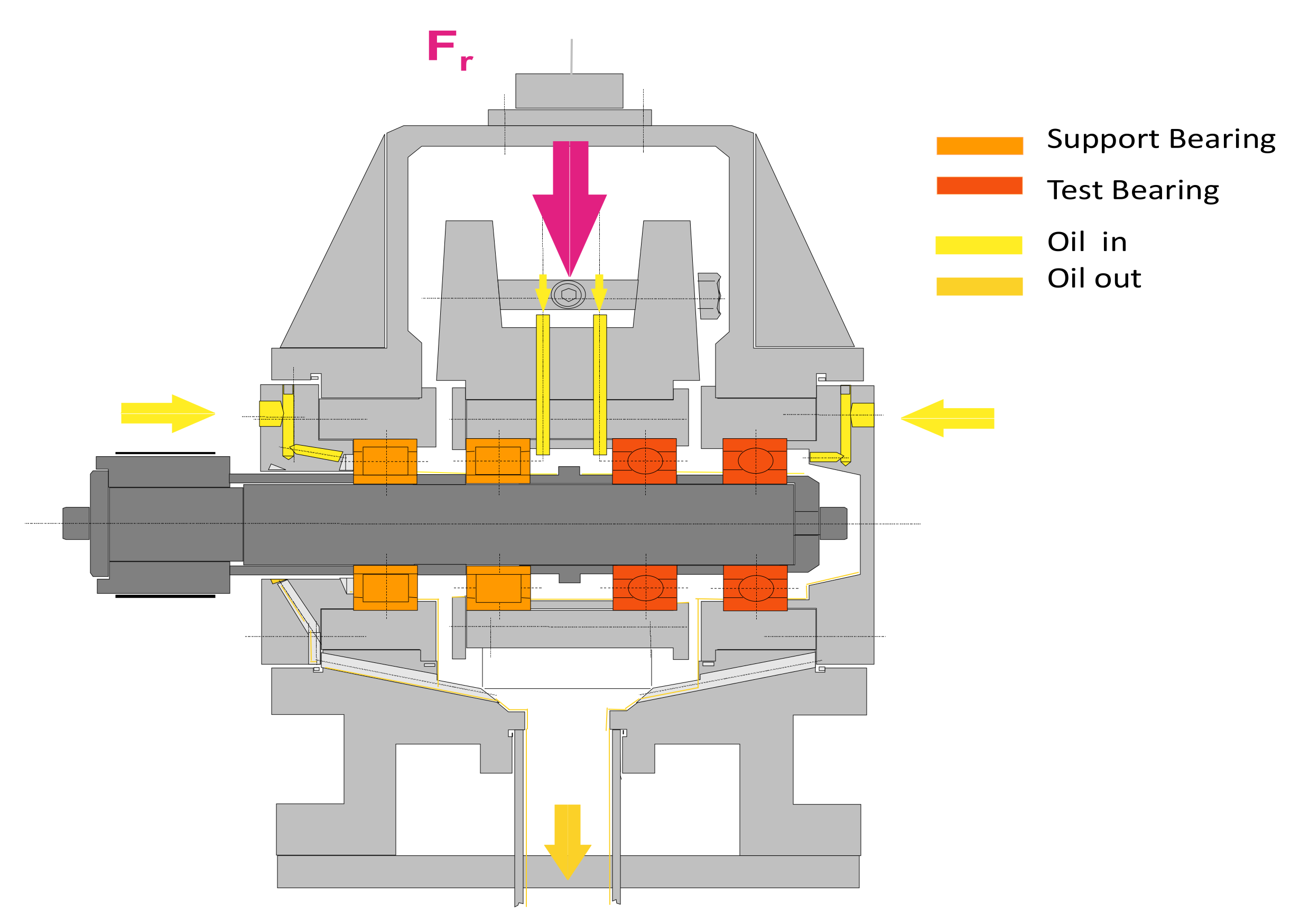
  • Mode 1: RCF (Rolling Contact Fatigue) test rig. Figure 1 represents the RCF test rig with a shaft attached to a motor with a rotation speed of 9000 rpm, a set of two slave bearings and two test bearings. The test bearings are radially loaded with 17 kN, 8.5 kN on each of them, resulting in a maximum Hertzian contact pressure of 3800 MPa at the inner ring. The oil is pumped axially through the bearing to an oil outlet. The temperature at the Outer Ring (OR) is regulated at 80 °C.
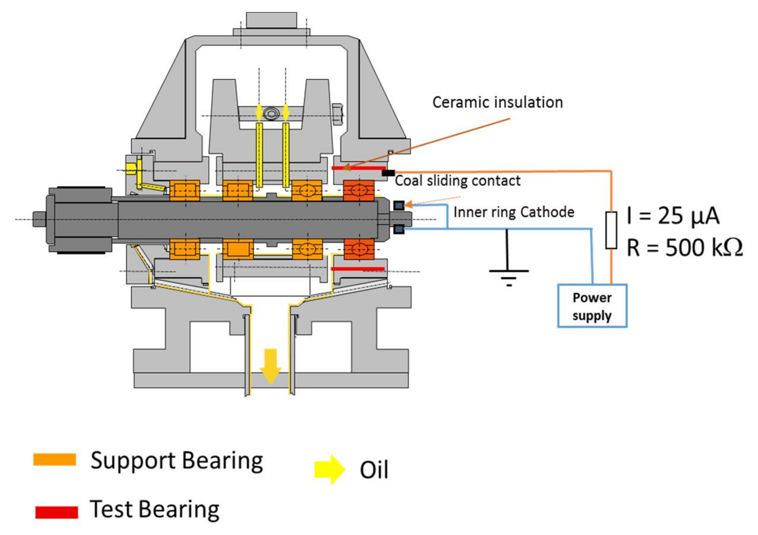
  • Mode 2: ECCF (Electrically Charged Contact Fatigue) test rig. Figure 2 represents the Mode 2 ECCF test rig. Three slave bearings and one test bearing are used. The test bearing was insulated from the housing by ceramic material and was subjected to an electric current to provoke WEC. A radial load of 4 kN was applied to the test bearing, equivalent to 2900 MPa contact pressure at the inner ring.
The reduction in the radial loading, deviating from Mode 1 (RCF) in the ECCF mode was due to very early and rapid failures in initial tests. The test bearing was electrically loaded via a slewing ring applying an average regulated DC current of 25 µA (
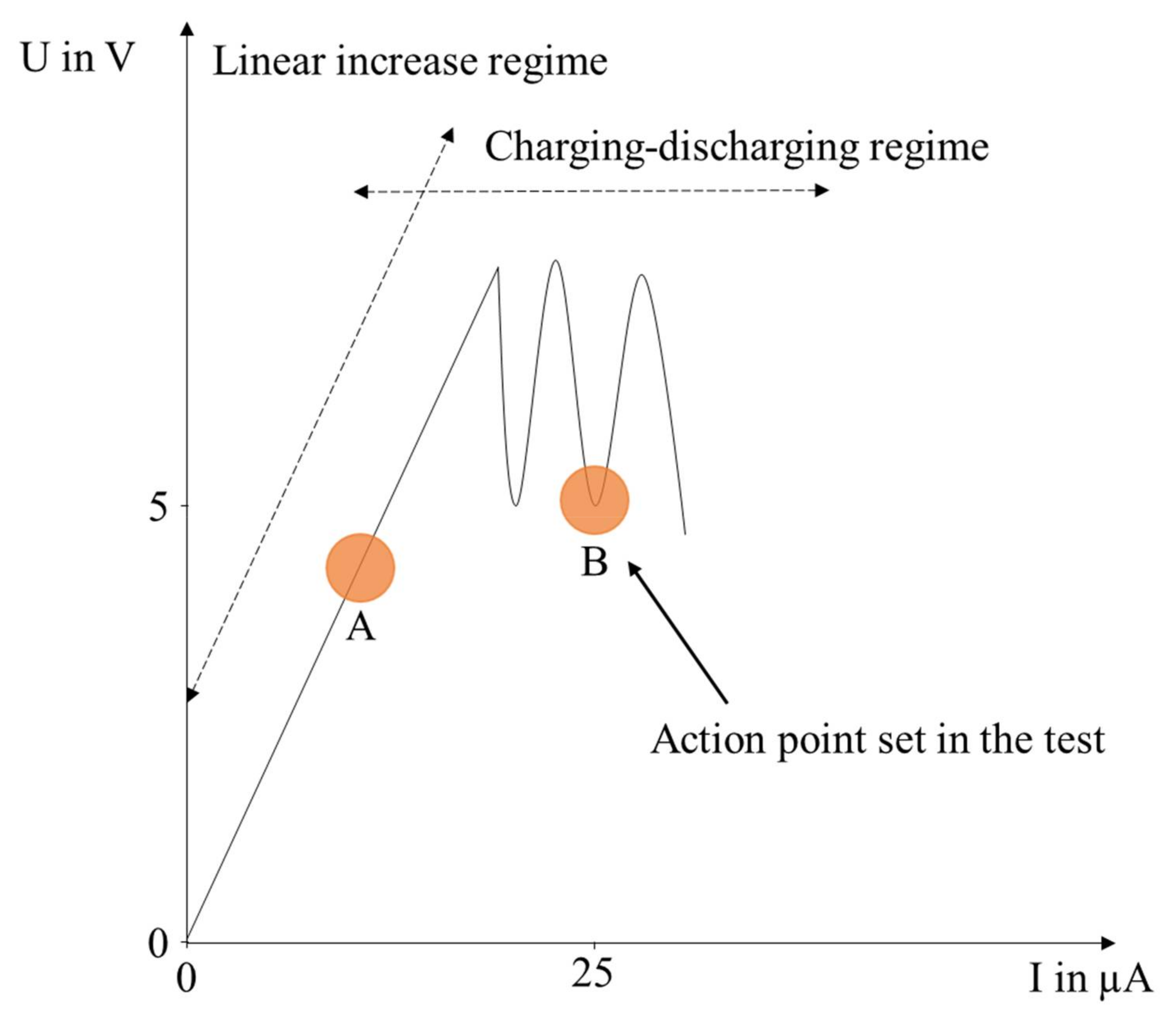
Figure 2), monitored by an oscilloscope. The cathode is at the carbon brush slewing ring on the rotating shaft, while the anode is at the outer ring. The tests started without electrical charging in order to reach full film lubrication. Afterwards, the charging took place, gradually increasing the DC current from 0 to 25 µA. In parallel, the voltage was recorded. After passing a regime of a linear increase in voltage by increasing the current, a discontinuous discharging took place by a further increase in the current (see Figure 3).
During pre-tests it became clear that by carrying out the tests in the linear regime, (Point A, Figure 3) WEC failures were not reproducible. Additionally, pre-tests proved that the failures only occur in the case of the low reference oil (see above), but not when only a base oil without additives is used at point B (Figure 3).

2.3. Procedure of the Microstructural Analyses

For all of the test conditions, circumferential cross sections of the inner rings were cut with precision saws, hot-mounted in a conductive resin and ground with Silicon Carbide (SiC) papers down to 5 µm average grain size. Subsequently, they were polished with diamond pastes down to 0.25 µm grain size, and finally polished with colloidal silica suspension of 50 nm grain size (OP-S) in order to achieve a flat and mechanically undeformed, polished surface. The thus prepared cross-sections could be used for orientation contrast imaging with Backscattered Electrons (BSE) in the Scanning Electron Microscope (SEM) as well as performing Electron Backscatter Diffraction (EBSD) and Energy Dispersive x-ray Spectroscopy (EDS) analyses (cf. [14]). Since a further etching of the cross-sections partially dissolves newly formed microstructure components, only the appearance of the microstructure in the OP-S polished state is presented in the present paper. Detailed comparisons of the appearance of AISI 52100 microstructures in OP-S polished and Nital-etched state can be found in [11,12,14]. The prepared specimens were analyzed in a JSM-7000F field emission gun SEM (JEOL Ltd., Tokyo, Japan). Orientation contrast images using BSE were collected at electron energies of 10 keV and working distances of approx. 5 mm. The contrasts in these images arise from differences in the electron backscattering depending on the incidence angles of the electron beam with respect to the lattice planes in the given crystallites in the specimen. Therefore, the BSE can be used to visualize the grain structure with high resolution. Additionally, specific areas of interest within these cross-sections were analyzed with EBSD using an attached Hikari EBSD camera by Ametek-EDAX (Mahwah, NJ, USA). EBSD maps were collected at 15 keV electron energy, approx. 30 nA probe current and with step sizes of 50 nm. The corresponding individual diffraction patterns were indexed with bcc-iron (as a candidate phase for martensite and ferrite), fcc-iron (for retained austenite) and orthorhombic Fe3C (for the spherical (Fe,Cr)3C particles). Martensite and ferrite are not directly distinguishable by the indexing, they can only be separated based on secondary parameters such as the pattern quality or the local misorientation cf. e.g., [15]. Evaluations relying on the correctness of the indexing are usually performed only for those points indexed with a software-internal “Confidence Index (CI)” larger than 0.1. For cubic materials, [16] has shown that this threshold corresponds to a probability of more than 95% to have a correct indexing result.
Since testing and microstructural investigations were time-consuming, only selected experiments (10 h, 15 h and 20 h of the ECCF mode) could be repeated and showed comparable results.

3. Results

3.1. Mode 1 (RCF)

The Mode 1 (RCF) tests results are presented in Table 2.
Starting from a pristine microstructure consisting mostly of martensite and spheroidized (Fe,Cr)3C carbides (Figure 4, untested), after 100 h of testing new equiaxed and elongated grains were observed (cf. magnified area of the 100 h image). The elongated grains are typically oriented under 30° angles with respect to the overrolling direction (in all of the images horizontal). In the course of the experiment these structures grow (Figure 4, 200 h,300 h, 670 h) and the elongated grains get accompanied by lenticular carbides with a ladder-like substructure (best visible in the image of the sample tested for 300 h (Figure 4, 300 h)). The area of the equiaxed grains grow as well as their grain size.
Figure 5 shows a Kernel Average Misorientation (KAM) map as a result of the EBSD measurements for the sample tested for 670 h. It depicts the average grain-internal orientation change over a distance of 100 nm, and shows that the equiaxed grains have lower misorientations, and therefore lower dislocation densities, compared to the martensitic surrounding. Together with the fact that they have a different texture, are surrounded by high-angle grain boundaries and finally also show a heavier etch attack by Nital etching (all three not shown), the results of these analyses reconfirm the idea that the equiaxed grains consist of recrystallized ferrite, which obviously grows with the duration of the tests (Figure 4). Additionally, Figure 5 shows, that in contrast to the equiaxed grains, the elongated grains show higher misorientations, which can be interpreted as the result of a formation under shear deformation. Their etching behavior points to a ferritic nature also of those elongated grains.
Excess carbon during the transition of martensite to ferrite is pushed into regions neighboring the elongated ferrite grains, where lenticular carbides are formed (Figure 5) [11].
Summarizing the results of these RCF tests, it has to be noted that all of the test stages already showed, besides dark etching areas, microstructural features connected to the low angle band stage of the classical RCF sequence. These structures grow in diameter and length with the test duration. The formation of high-angle bands did not set in within the maximum testing time of 670 h.

3.2. Mode 2 (ECCF)

The Mode 2 (ECCF) test rig results are presented in Table 3.
Compared to the RCF test rig results (Table 2) the bearings failed, even under moderate conditions in an early stage by massive spalling. The bearings failed after less than 100 h, mainly at 50 h. As within the former results, the tests were halted at earlier stages of the spalling process, starting from the failed 50 h sample, stepwise going back to 20 h and 10 h (Table 3). Figure 6 shows some exemplary micrographs of the bearings tested under ECCF conditions. In [12], the authors pointed out that the microstructural alterations observed for WEC and RCF samples show many similarities but differ in the occurrence of nanocrystalline regions and cracks.
From about 20 h onwards, the typical nanocrystalline White Etching Matter (WEM, the brighter regions in Figure 6) and the accompanying cracks are observed. According to earlier Transmission Electron Microscopy (TEM) and Atom Probe Tomography (APT) analyses (e.g., in [12,17]) these nanocrystals within the WEM are considered as ferritic with a carbon enrichment on the grain boundaries.
Besides this nanocrystalline WEM, also coarser, equiaxed and elongated ferrite grains (cf. [12], visible e.g., in the top right image of Figure 6), and the accompanying cracks can be found, especially in later stages of the test sequence. Figure 7 shows a KAM map comparable to Figure 5 for a fully developed WEC region. As can be seen, the nanocrystalline regions, for which the grain structure cannot be resolved by EBSD, are intermixed with areas of equiaxed and elongated ferrite grains with similar characteristics as in the RCF case, but less geometric ordering.
In the samples suspended at 15 h and earlier, only microcracks with a few µm length and sparingly formation of crack networks were observed. Since microstructural alterations at the vicinity of these microcracks are scarce, further analyses will be needed to clarify the exact mechanisms how these microcracks contribute to the formation of the WEA.
Figure 8 shows that early stages of microstructure alteration are already distributed asymmetrically around the crack tips of a microcrack, while they are absent across the central crack flanks.

4. Discussion

This study shows that the fatigue behavior of the bearings from Mode 1 (RCF) tests differ from those apparent in the conditions leading to Mode 2 (ECCF). While the Mode 1 (RCF) tested bearings did not fail, even after passing 109 load cycles, the bearings exposed to the Mode 2 (EECF) test conditions only reached approximately 10
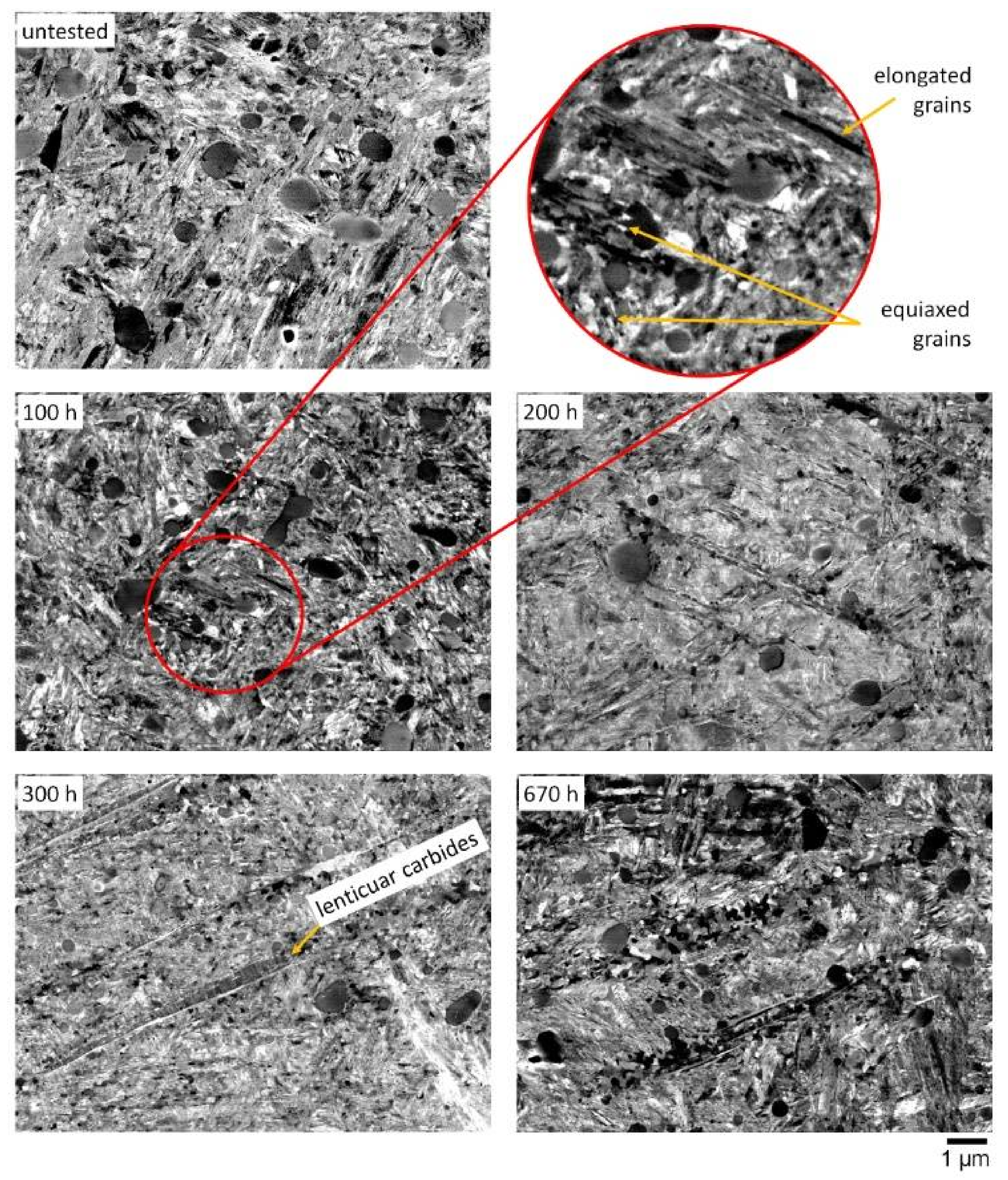
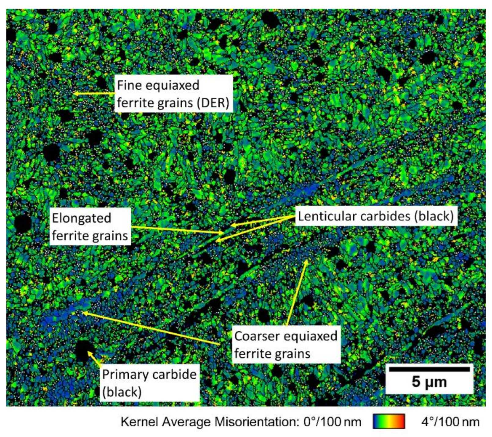
8 load cycles. This is remarkable as the radial load during the Mode 2 (ECCF) test conditions was roughly half the load compared to the Mode 1 (RCF) tests and the Hertzian pressure was 24% less in the Mode 2 (ECCF) tested bearings. The material processes comparing Mode 1 (RCF) and Mode 2 (ECCF) tests differ accordingly over the test duration: within the Mode 1 (RCF) tests, the material undergoes a slow and continuous progression of the martensitic microstructure towards the formation of elongated and equiaxed grains (see Figure 4). These elongated grains start to pass and cut the primary carbides. The area of equiaxed grains in the Mode 1 (RCF) tests consist of ferrite with low dislocation densities, while the elongated grains show higher internal dislocation densities, probably introduced by the growth under shear deformation (Figure 5).
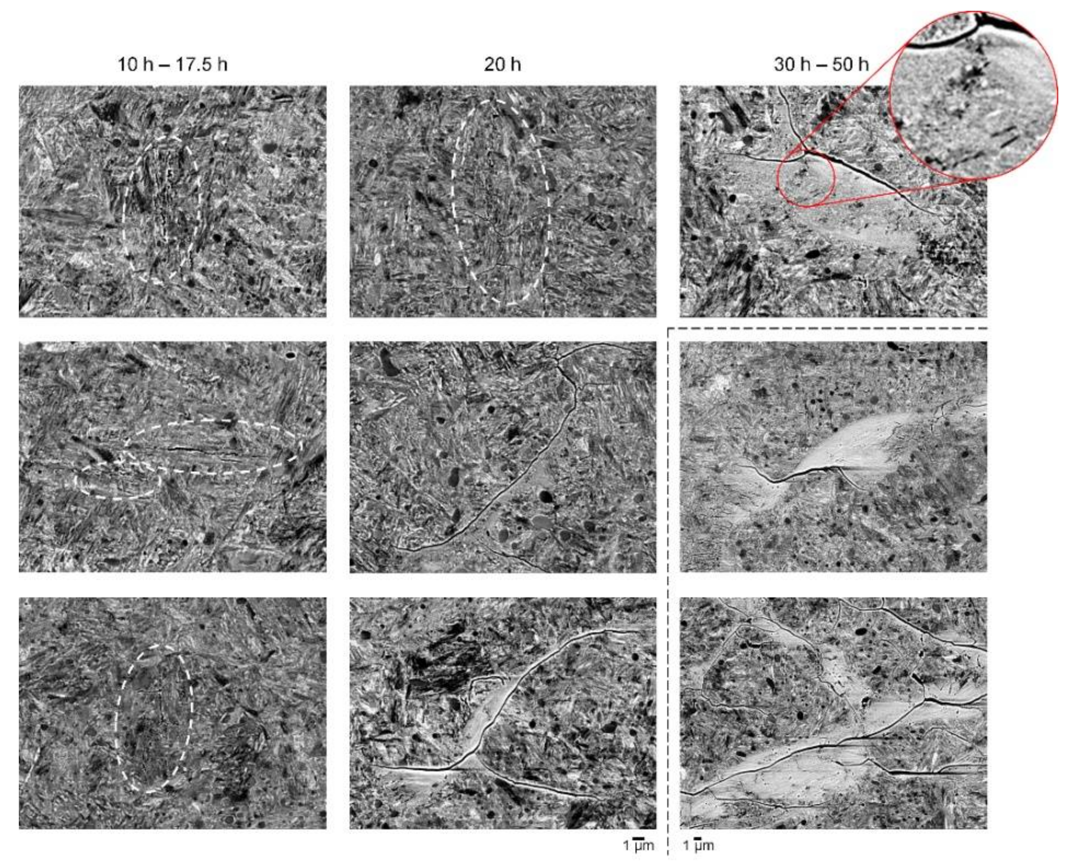
In contrast, the bearings tested in the Mode 2 (ECCF) show the formation of single and rapidly growing microcracks passing the microstructure. It is noteworthy that neither the single cracks nor the crack networks in the early stage are accompanied by WEA. WEA appear in a later state compared to the initiation at a time nearly twice as long (
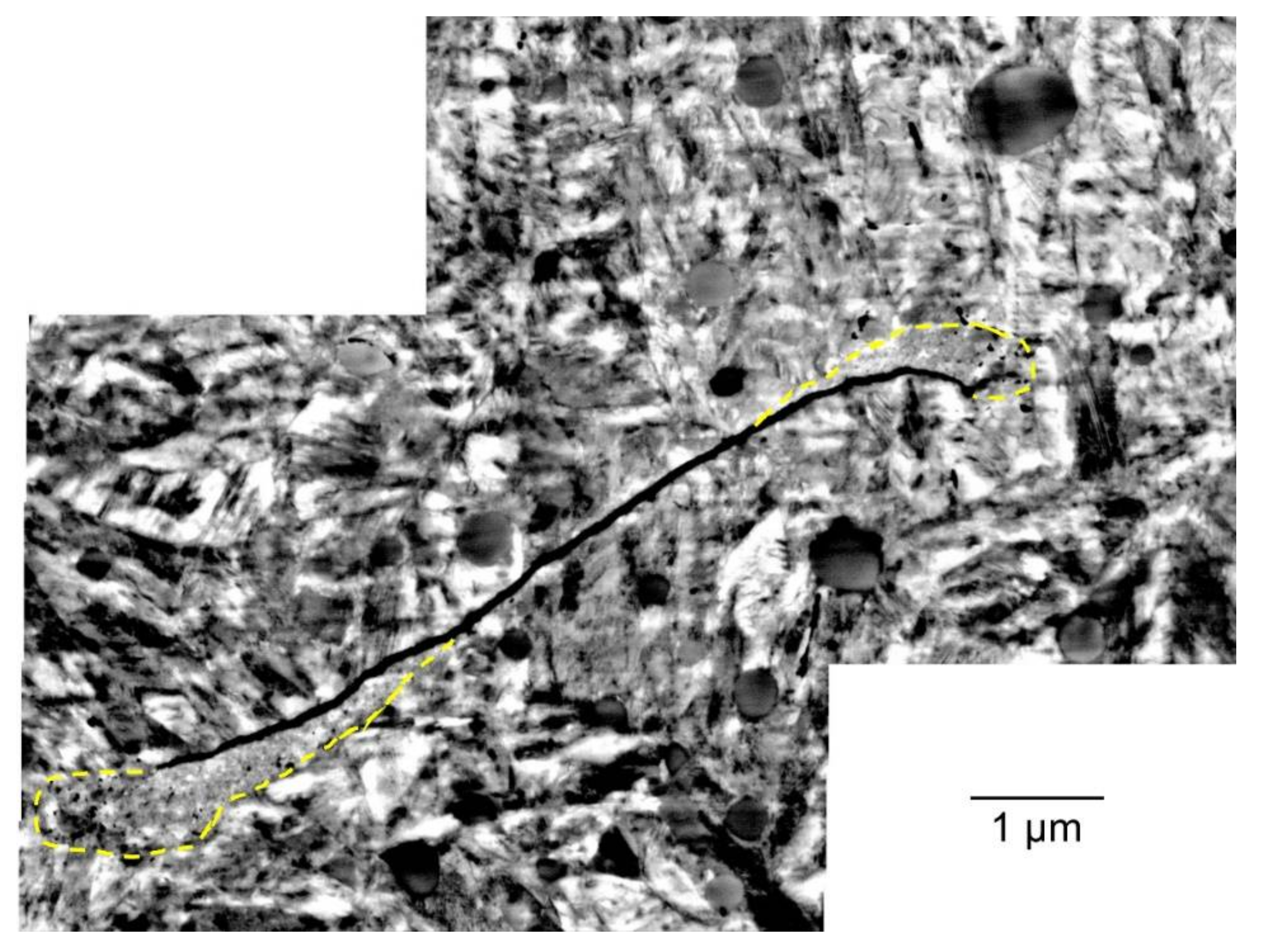
Figure 6). The carbides are partially sliced by the cracks. The late progression of WEA compared to the crack formation as well as the asymmetry of observed early microstructure alterations in the vicinity of the microcracks (cf. Figure 8), however, make it unlikely that these WEA are formed by flank rubbing of the observed microcracks as e.g., proposed in [18]. Flank rubbing should lead to the formation of WEA at the flank sides, while this is rather observed at the crack tips. According to recent studies [19], it is more likely that stress concentrations at the crack tip are promotors for the percolation towards crack networks.
Neither the tests with the low reference lubricant in the absence of electrical charging–discharging led to the formation of cracks and WEA, nor those tests carried out with the pure base oil (lubricant without functional additives) under the influence of electrical charging.
These findings show that solely charging–discharging in the tribocontact does not lead to cracks and WEA. Instead, the combination of electrical charging–discharging and the presence of chemicals, represented by the additives, lead to the formation of cracks and WEA.
Subsurface cracking as an initial feature is reported to be the dominant fatigue mechanism in Very High Cycle Fatigue/Ultra High Cycle Fatigue (VHCF/UHCF) tests [10,20,21]. According to this, the results of the tests here could be interpreted as a rapid acceleration of VHCF/UHCF fracture, solely comparing the load cycles, but also the progression of the cracks.
VHCF/UHCF studies prove the formation of Fine Granular Area (FGA) and/or non-metallic inclusions as promotors of microcracks, which then evolve. It might well be that the formation of Fine Granular Area (FGA) is facilitated by an incidental temperature rise, due to electrical discharging as in Mode 2 (ECCF). However, the fact that even in the presence of lightning the pure base oil does not create WEC but only in the presence of additional chemicals, shows that the process is stimulated by chemicals. While the importance of the presence of chemicals is evident, their contribution remains unclear. It could well be that the chemicals are sources of hydrogen or other gases. However, the finding that WEA was observed in a total non-hydrogen atmosphere is contradictive [14].
The apparently late formation of WEA leads to the assumption, that the formation of WEA in this test sequence may be a secondary effect with a different mechanism while the subsurface crack initiation is a primary effect. However, the reasons and precise understanding of the relation of both, crack formation and WEA formation, and their progression towards WEA-decorated cracks, remain unclear up to now.
Hence, the reasons and the precise understanding of both, crack formation and the progression towards WEA decorated cracks, remain unclear up to now.
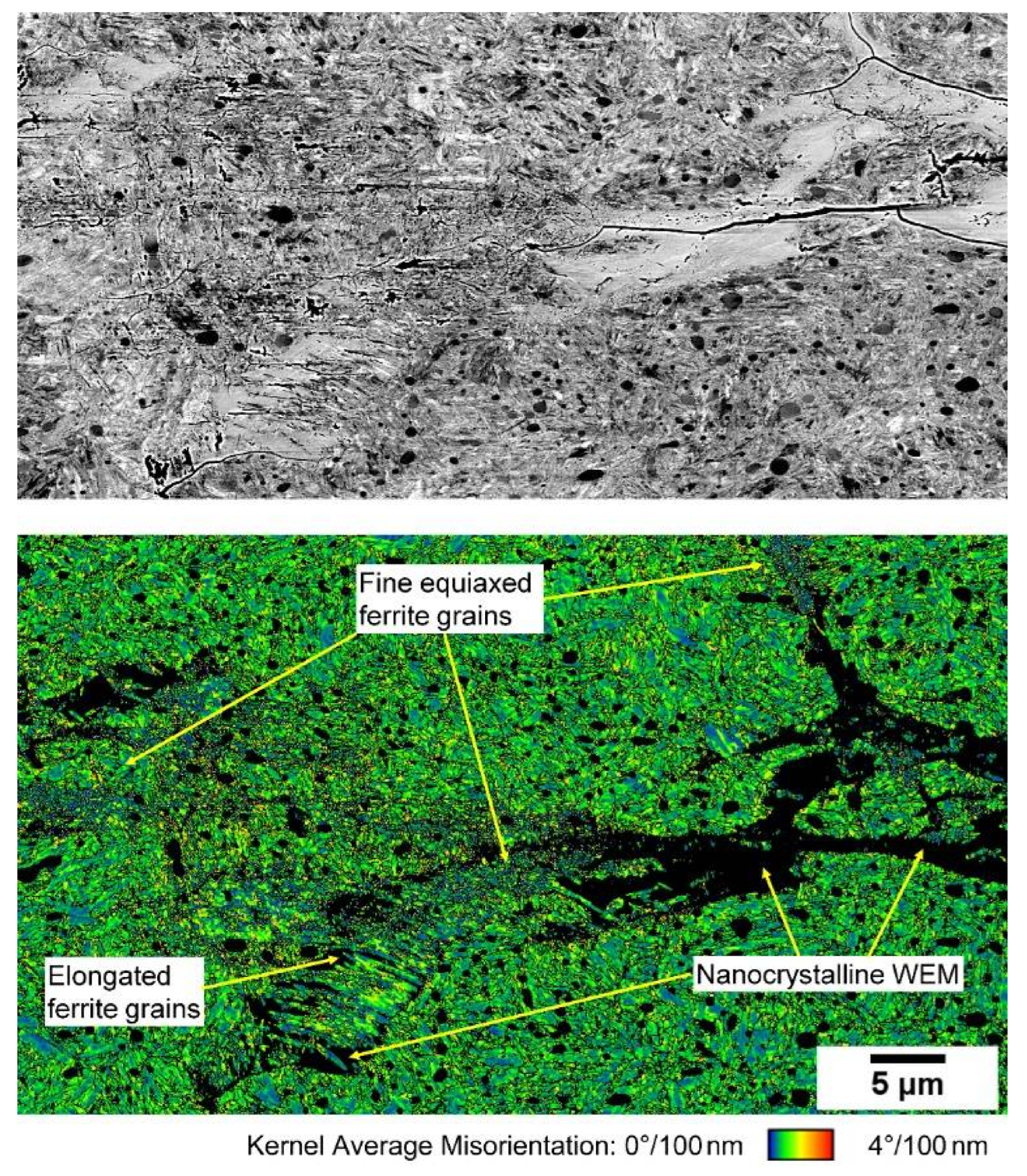
While there are many similarities in the observed microstructure transformations, the results show that RCF and WEC differ with respect to the occurrence of nanocrystalline material in the WEC case, and especially with respect to the temporal evolution of the material microstructure.
The test results show that the material SAE 52100, which was chosen for this study, responds very sensitively to the initial conditions.

5. Conclusions

DGBB tests under EHL conditions with full film lubrication were carried out using a high functionalized gear oil (ISO VG 46). The tests were carried out in two modes:
  • Mode 1 (called RCF) where the bearings were simply under radial load and full film lubricated;
  • Mode 2 (called ECCF) with reduced pressure and an applied low level DC current (25 µA).
The bearings were suspended at different time steps in order to see the beginning and the progression of the changes in the material microstructure with respect to the applied load.
Mode 1 (called RCF) bearings show the formation of equiaxed and elongated ferrite grains in the subsurface, starting at 100 h testing (2.9 × 10⁸ load cycles) and slowly, but significantly progressing while load cycles reach up to 109. While the area of the equiaxed grains represents stress free, recrystallized ferrite, the elongated grains show higher dislocation densities.
Mode 2 (called ECCF) bearings show the early formation of microcracks passing the microstructure with a progression to crack networks with WEA decoration.
The results of these tests show the differences between the RCF and the ECCF route. However, it is evident from the experimental parameters that the material responds very sensitively to small changes in the experimental conditions.

Author Contributions

Conceptualization, W.H. and L.W. and V.R.; methodology, W.H. and L.W. and A.S. and V.R.; formal analysis, A.S. and V.R.; investigation, A.S. and V.R. and W.H.; resources, W.H. and J.M.; data curation, A.S. and V.R.; writing—original draft preparation, W.H.; writing—review and editing, W.H. and A.S. and J.S. and J.W. and C.B. and L.W.; supervision, W.H. and L.W. and J.M.; project administration, W.H. and L.W.; funding acquisition, W.H. All authors have read and agreed to the published version of the manuscript.

Funding

This research was funded by Schaeffler Technologies AG & Co. KG.

Institutional Review Board Statement

Not applicable.

Informed Consent Statement

Not applicable.

Data Availability Statement

All data will be made available on request to the correspondent author’s email with appropriate justification.

Acknowledgments

The authors would like to thank Schaeffler Technologies AG & Co. KG for carrying out the tests and supervising. J.S. and J.M. acknowledge the support of the DFG in the framework of project MA 1280/57-1.

Conflicts of Interest

The funders had no role in the design of the study; in the collection, analyses, or interpretation of data; in the writing of the manuscript, or in the decision to publish the results.

References

  1. Scott, D.; Loy, B.; Mills, G.H. Paper 10: Metallurgical Aspects of Rolling Contact Fatigue. Proc. Inst. Mech. Eng. Conf. Proc. 1966, 181, 94–103. [Google Scholar] [CrossRef]
  2. Gegner, J.; Nierlich, W. Frictional surface crack initiation and corrosion fatigue driven crack growth. In Proceedings of the Wind Turbine Tribology Seminar, Broomfield, CO, USA, 15–17 November 2011. [Google Scholar]
  3. Tamada, K.; Tanaka, H. Occurrence of brittle flaking on bearings used for automotive electrical instruments and auxiliary devices. Wear 1996, 199, 245–252. [Google Scholar] [CrossRef]
  4. Kino, N.; Keizo, O. The influence of hydrogen on rolling contact fatigue life and its improvement. JSAE Rev. 2003, 24, 289–294. [Google Scholar] [CrossRef]
  5. Harada, H.; Mikami, A.T.; Shibata, M.; Sokai, D.; Yamamoto, A.; Tsubakino, H. Microstructural changes and crack initiation with white etching area formation under rolling/sliding contact in bearing steel. ISIJ Int. 2005, 45, 1897–1902. [Google Scholar] [CrossRef] [Green Version]
  6. Gegner, J. Tribological Aspects of Rolling Bearing Failures; InTech Europe: London, UK, 2011; pp. 33–94. [Google Scholar]
  7. Evans, M.H. An updated review: White etching cracks (WECs) and axial cracks in wind turbine gearbox bearings. Mater. Sci. Technol. 2016, 32, 1133–1169. [Google Scholar] [CrossRef]
  8. Pérez, J.M.P.; Márquez, F.P.G.; Tobias, A.; Papaelis, M. Wind turbine reliability analysis. Renew. Sustain. Energy Rev. 2013, 23, 463–472. [Google Scholar] [CrossRef]
  9. López-Uruñuela, F.J.; Fernández-Díaz, B.; Pagano, F.; López-Ortega, A.; Pinedo, B.; Bayón, R.; Aguirrebeitia, J. Broad review of “White Etching Crack” failure in wind turbine gearbox bearings: Main factors and experimental investigations. Int. J. Fatigue 2021, 145, 106091. [Google Scholar] [CrossRef]
  10. El Laithy, M.; Wang, L.; Harvey, T.J.; Vierneusel, B.; Correns, M.; Blass, T. Further understanding of rolling con-tact fatigue in rolling element bearings—A review. Tribol. Int. 2019, 140, 105849. [Google Scholar] [CrossRef]
  11. Šmeļova, V.; Schwedt, A.; Wang, L.; Holweger, W.; Mayer, J. Electron microscopy investigations of microstruc-tural alterations due to classical Rolling Contact Fatigue (RCF) in martensitic AISI 52100 bearing steel. Int. J. Fatigue 2017, 98, 142–154. [Google Scholar] [CrossRef]
  12. Šmeļova, V.; Schwedt, A.; Wang, L.; Holweger, W.; Mayer, J. Microstructural changes in White Etching Cracks (WECs) and their relationship with those in Dark Etching Region (DER) and White Etching Bands (WEBs) due to Rolling Contact Fatigue (RCF). Int. J. Fatigue 2017, 100, 148–158. [Google Scholar] [CrossRef]
  13. El Laithy, M.; Wang, L.; Harvey, T.J.; Vierneusel, B. Semi-empirical model for predicting LAB and HAB for-mation in bearing steels. Int. J. Fatigue 2021, 148, 106230. [Google Scholar] [CrossRef]
  14. Diederichs, A.M.; Schwedt, A.; Mayer, J.; Dreifert, T. Electron microscopy analysis of structural changes within white etching areas. Mater. Sci. Technol. 2016, 32, 1683–1693. [Google Scholar] [CrossRef]
  15. Ryde, L. Application of EBSD to analysis of microstructures in commercial steels. Mater. Sci. Technol. 2006, 22, 1297–1306. [Google Scholar] [CrossRef]
  16. Field, D.P. Recent advances in the application of orientation imaging. Ultramicroscopy 1997, 67, 1–9. [Google Scholar] [CrossRef]
  17. Li, Y.J.; Herbig, M.; Goto, S.; Raabe, D. Atomic scale characterization of white etching area and its adjacent ma-trix in a martensitic 100Cr6 bearing steel. Mater. Charact. 2017, 123, 349–353. [Google Scholar] [CrossRef]
  18. Morsdorf, L.; Mayweg, D.; Li, Y.; Diederichs, A.; Raabe, D.; Herbig, M. Moving cracks form white etching areas during rolling contact fatigue in bearings. Mater. Sci. Eng. A 2020, 771, 138659. [Google Scholar] [CrossRef]
  19. Curd, M.E. Subsurface Crack Propagation in Bearing Steels. Ph.D. Thesis, The University of Manchester, Manchster, UK, 2020. [Google Scholar]
  20. Averbeck, S.; Spriestersbach, D.; Kerscher, E. Crack growth and microstructural changes in AISI 52100: White etching cracks (WEC) and fine granular area (FGA). In Proceedings of the ICMFF12—12th International Conference on Multiaxial Fatigue and Fracture, Bordeaux, France, 24–26 June 2019; Volume 300, p. 18001. [Google Scholar]
  21. Averbeck, S.; Spriestersbach, D.; Kerscher, E. Mechanism of fine granular area and white etching crack for-mation in AISI 52100 bearing steel. Theor. Appl. Fract. Mech. 2020, 108, 102664. [Google Scholar] [CrossRef]
Figure 1. Schematic representation of the Mode 1 (RCF) test rig.
Lubricants 10 00024 g001
Figure 2. Schematic representation of the Mode 2 (ECCF) test rig.
Lubricants 10 00024 g002
Figure 3. Schematic representation of the charging regime. The tests are carried out at point B (25 µA, DC) at a voltage of 5 V. The discharging by the increase in the DC current is continuously progressing (not shown here).
Lubricants 10 00024 g003
Figure 4. Orientation contrast BSE images of the untested martensite structure and of the microstructures of the RCF tested bearings suspended at 100 h, 200 h, 300 h, and 670 h.
Lubricants 10 00024 g004
Figure 5. EBSD KAM map for the points indexed as ferrite from the 670 h sample.
Lubricants 10 00024 g005
Figure 6. Orientation contrast BSE micrographs from the cross-sections of the mode 2 (ECCF) tests.
Lubricants 10 00024 g006
Figure 7. BSE map for the localization of the cracks and EBSD KAM map for the points indexed as ferrite from the 50 h WEC sample (please note: the area measured with EBSD extends the BSE-imaged area at the top for approx. 5 µm).
Lubricants 10 00024 g007
Figure 8. Distribution of the microstructure alteration (marked by dashed lines) in the vincinity of a small microcrack from the 20 h sample.
Lubricants 10 00024 g008
Table 1. Chemical composition of the SAE 52100 material used in this study.
CCrMnSiNiCuAlMoSCoPSnZn
1.011.570.440.250.060.040.020.030.005 <0.01
Table 2. Mode 1 (RCF) test results.
Test Duration (h)Load Cycles (×106)Failure
100293No
200587No
300880No
4001173No
6701965No
Table 3. Mode 2 (ECCF) test results.
Test Duration (h)Load Cycles (×106)Failure
1029No
12.537No
1544No
17.551No
2059No
3088No
40117Yes (inner ring)
50147Yes (inner ring)
Publisher’s Note: MDPI stays neutral with regard to jurisdictional claims in published maps and institutional affiliations.

