Article

Lubrication Modelling of Artificial Joint Replacements: Current Status and Future Challenges

1
Engineering Department, Nottingham Trent University, Nottingham NG1 4FQ, UK
2
College of Mechanical and Electrical Engineering, Qingdao University, 308 Ningxia Road, Qingdao 266071, China
3
Tribology Research Institute, School of Mechanical Engineering, Southwest Jiaotong University, Chengdu 610031, China
4
School of Mechanical Engineering, University of Leeds, Leeds LS2 9JT, UK
*
Authors to whom correspondence should be addressed.
Lubricants 2022, 10(10), 238; https://doi.org/10.3390/lubricants10100238
Submission received: 8 August 2022 / Revised: 21 September 2022 / Accepted: 22 September 2022 / Published: 27 September 2022
(This article belongs to the Special Issue Modelling in Tribology and Biotribology)

Abstract

:
This paper reviews the recent advancements in computational modelling of the lubrication of hip and knee joint replacements, especially those concerning Professor Duncan Dowson’s contribution. The review starts with the development of modelling the five key parameters that appeared in the pioneered Hamrock–Dowson formula. Then, the theory and approaches for the mixed lubrication in which the artificial hip and knee joint replacements operate are reviewed. We also discuss the current challenges in modelling the lubrication behaviour of joint replacements and how these challenges could be addressed in future studies. These challenges include the mixed lubrication theory, the numerical complexities due to complicated realistic geometry, material and rheology, and individual physiological diversities.

Graphical Abstract

1. Introduction

The hip and knee joints are important articulations of the human body; they support the body weight and dynamic loading and provide various types of movements during daily activities. Total hip and knee joint replacement (THR and TKR) surgery is a treatment for end-stage arthritis to regain joint functions and relieve pain. More than 200,000 hip and knee prostheses implanted annually in the UK [1], and this number is still growing along with the ageing population. Around 90% of total hip replacements last after 15 years, but this number falls to 58–78% after 25 years [2], which cannot satisfy demands for living a high-quality life. One of the main problems limiting hip implants’ lifetime is the wear and wear particles generated during long-term wear from the artificial materials. The particles can cause adverse biological reactions with the tissue around the joint; this is known as bone absorption and inflammation [3]. As wear is one main reason that causes problems, minimising wear has become the primary strategy to increase the lifetimes of artificial joint implants.
Investigating the fundamental tribological performances of joint replacements has been a critical aspect of bio-tribology ever since this fascinating field was defined by Professor Duncan Dowson in the early 1970s [4,5]. Understanding the lubrication of joint replacements is important because it contributes to a full appreciation of the tribological behaviour of joint replacements [6]. Indeed, from the tribological point of view, an effective reduction in the direct contact between the bearing surfaces by the lubricant can reduce wear and wear debris, thereby reducing the risk of adverse biological reactions caused by wear debris.
The development of the lubrication analysis can be traced back to an empirical formula developed by Hamrock and Dowson in 1978 [6,7], as shown in Equation (1). It was used to estimate the minimum film thickness in a full film lubrication regime, including elastohydrodynamic lubrication (EHL), given just a few parameters from geometry, solid and fluid materials, loading, and motion. These parameters indicate the main areas where studies on lubrication analyses have been focused to date. With the development of both experimental and modelling technologies, each of these factors has been explored to investigate more realistic and complicated conditions. This paper will present details on how these parameters are studied, particularly the development of the numerical models describing these factors.
h m i n = 2.8 R ( η u E R ) 0.65 ( w E R 2 ) 0.21
R′ is the equivalent radius (m); E′ is the equivalent elastic modulus (Pa); η is the dynamic fluid viscosity (Pa·s); u is the entrainment velocity (m/s); w is the load (N).
Another important parameter that was not coupled with the Hamrock–Dowson formula is time, as the formula only describes the steady-state conditions. However, all the parameters mentioned in the formula can change with time. Contact geometry can change during the motion of joint rotations; surface geometry can change during long-term wear; a viscoelastic characteristic indicating a time delay exhibits both polymer materials and synovial fluids, and loading and motion changes in the time of all activities.
However, direct measurements of the lubrication of joint replacements in vivo are still not possible due to the lack of techniques for monitoring the lubricant film in the human body. Even measuring the lubricant film thickness of joint replacements in vitro is difficult due to the complicated geometry, material combinations and the complex physiological motion and loading experienced in daily life. Only simplified contacts and material or simplified loadings and motions could be considered using the optical interferometry technique [8,9].
Computational modelling of lubrication in joint replacements is essential to this field. Fortunately, the full film lubrication of joint replacements can be computationally modelled, especially using the elastohydrodynamic lubrication (EHL) theory pioneered by Professor Duncan Dowson [10,11,12,13,14]. Numerous studies on the lubrication behaviour of joint replacements based on the EHL theory have been published since 1966 [15], many of which Professor Duncan Dowson himself had significantly contributed. These studies have provided fundamental insights into understanding the lubrication performances of joint replacements, and the conclusions have provided essential guidelines for developing joint replacements.
Challenges in modelling the lubrication of joint replacements remain. Although mixed lubrication has been well recognised as the dominant lubrication regime in previous analyses [16], modelling mixed lubrication in joint replacements is still very challenging. It is mainly due to the not-well-established mixed lubrication mechanism, the high computational costs required to model the bearing surfaces within a relatively large contact area, and the complexity of geometry. Moreover, recent experimental studies revealed a protein aggregation lubrication mechanism for the synovial lubrication of joint replacements, which could not be well predicted by the classic Newtonian EHL theory [17,18,19,20].
Therefore, this paper reviews the recent advancements in computational modelling of the lubrication of joint replacements, especially those with Professor Duncan Dowson’s contribution, and discusses the key challenges in modelling the lubrication behaviours of joint replacements and how these challenges could be addressed. The structure of this review paper is arranged as follows.
The lubrication and mixed lubrication modelling work are reviewed in two main sections separately. Section 2 reviews the general lubrication model, including geometry and materials, surface deformation, loading and motions, and viscosity constitutive models. Section 3 summarises the three main mixed lubrication approaches applied to the model hip and knee joint replacements, including their advantages and disadvantages. Section 4 presents the discussion on the challenges in the lubrication models and what could be improved, including the mixed lubrication theory, methods to address more realistic geometry, material properties, individual diversities, and the validation of models. The last section is a conclusion of the overall discussion.

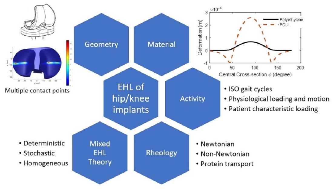
2. Lubrication Modelling of Hip and Knee Replacements

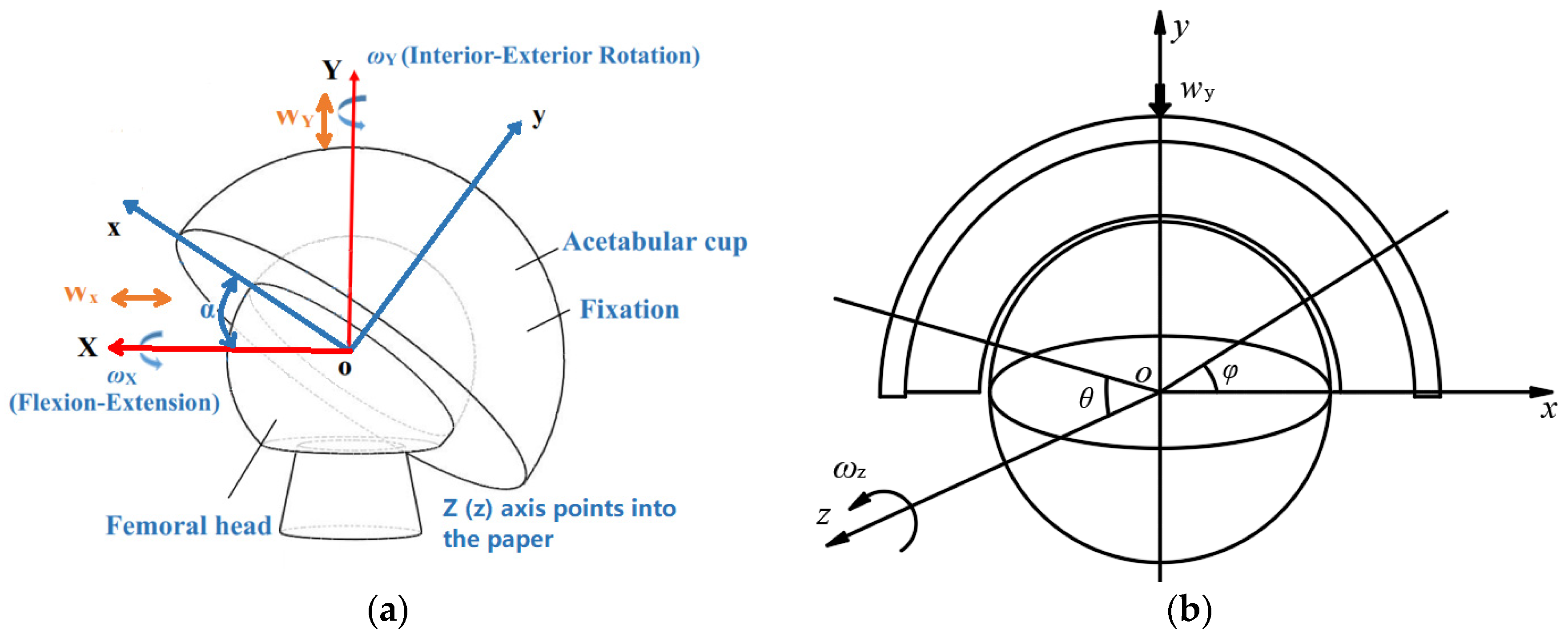
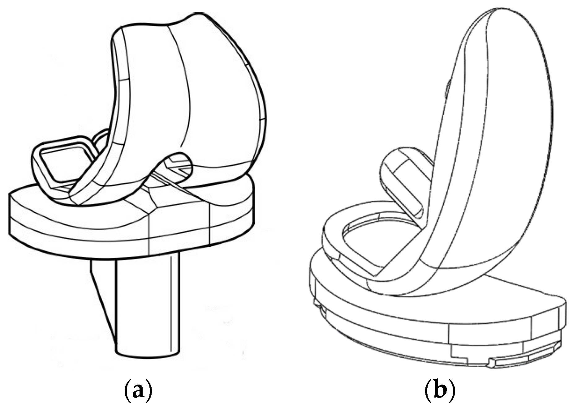
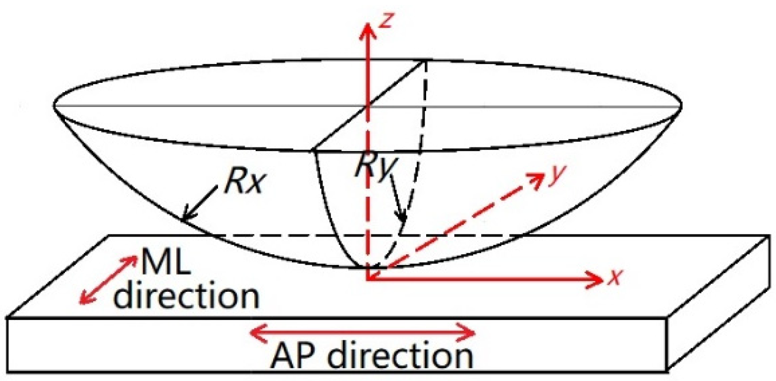
2.1. Geometries of Contact Surfaces

A ball-in-socket geometry with multiple radii was developed from a ball-on-plane geometry with a single radius. With more dimensions added, non-spherical profiles, surface roughness and texturing have been explored.
A typical artificial hip joint, consisting of a femoral head and an acetabular cup, is often simplified as a ball-in-socket model. Anatomically, the acetabular cup is positioned in the human pelvis or cup holder of a joint simulator with an inclined angle between 30° to 45°, illustrated as the angle α between the blue and red coordinate system in Figure 1a. The red coordinate system, having the y-axis pointing in the superior direction, rotates by an angle α along its z-axis to form the blue coordinate system. In Figure 1, angles θ   and   φ are spherical coordinates, which are often used to describe the lubrication governing equations for the hip joint model; w indicates loading and ω indicates the rotations. It is reasonable to rotate the cup into a horizontal position when the contact area is within the cup and away from the contact edge, as shown in Figure 1b, without affecting the lubrication results [21,22]. However, such a simplified rotation would not apply when there is an edge-loading contact.
The geometrical parameters, particularly diameter and diametral clearance, are important factors in the lubrication analysis. Considering the ideal spherical geometry of hip replacements, the head with a larger diameter will result in a larger contact dimension, larger sliding distance, lower pressure, and thicker film; while a larger diametral clearance between the two bearing surfaces will result in a smaller contact dimension, smaller sliding distance, higher pressure, and thinner film. This can be predicted by the Hamrock and Dowson formula [7,16] and EHL full numerical analysis [23]. However, the calculation is based on steady-state full film lubrication [24,25]. For MoM hip implants, small heads of diameters 16 and 22.225 mm showed linearly increased volumetric wear with increasing head diameters, because the mixed lubrication was dominant and thicker films were not established with the head size increase, while the contact dimension and the sliding distance increased with the head diameter that contributed to the wear. For heads of diameters 28 mm and greater, a dramatic reduction in steady-state wear was observed due to more load proportions supported by the fluid–film lubrication with increased entrainment velocity [16,26]. Large heads of diameters 44–48 mm showed increased wear with increasing head diameters, again, where the disadvantages (obtained from increased sliding distances) were more than the advantages from the decreased pressure [27].
The actual joint replacements are not purely spherical; the measured roundness perturbations of the cup or head components were in the range of 0.01–0.1 mm [28]. Thus, the non-sphericity of the bearing surface was also considered either for the femoral head or the acetabular cup, such as an elliptical geometry [29,30]. An optimised Alpharabola profile [31] was proposed for better lubrication [32,33]. The EHL simulation of the Alpharabola profile provided theoretical evidence for the new design of the hip prosthesis, the aSphere® M-Spec series, manufactured by Depuy Synthes (the Orthopaedics Company of Johnson & Johnson, Raynham, MA, USA). Gao et al. [34] proposed a pre-worn surface profile inspired by the running-in and steady-state two-stage wear performance. The geometrical parameters of both spherical and non-spherical bearings are summarised in Table 1.
Highly conforming is the main characteristic of the artificial hip joint. In contrast, the knee implant has lower conformity. Based on the common knee implants, the tibial liner is either slightly curved (Figure 2a) or even much flatter (Figure 2b). Articulating surfaces of the knee implant at a particular flexion are determined by four radii, the radius of the femoral head in medial-lateral (ML) and anterior-posterior (AP) directions (RF,ML and RF,AP), as well as radii of the tibial component in both directions (RT, ML and RT, AP), as shown in Figure 3. Knee joint replacements have various designs in five key areas [38,39]: (i) the shape of the femoral and patellar components, (ii) the position and alignment of the components, (iii) bone preparation, (iv) materials, and (v) the stability. The geometrical parameters of the knee implants are summarised in Table 2.
In addition to the ball-in-socket model, a ball-on-plane equivalent model (Figure 4) is also reasonable to simulate some cases of hip implants, as well as knee implants. In terms of the knee implant, the effective radii in the AP and ML directions can be calculated as follows
1 R x = 1 R F , A P 1 R T , A P
1 R y = 1 R F , M L 1 R T , M L
The actual bearing surfaces are by no means smooth, and the magnitudes of surface roughness are different for various component materials. The composite roughness varies in the range of 0.014–0.071 μm for the hard-on-hard bearing surfaces (MoM and CoC) and 0.1–2 μm for the hard-on-soft bearing surfaces (MoP and CoP) [35,37,42].

2.2. Materials

The ideal biomedical material for hip and knee implants requires (i) good biocompatibility to avoid adverse biological reactions or inflammation; (ii) high mechanical resistance to avoid excessive friction, which may cause heat generation and noise at the bearing surfaces, fatigue, and fretting, which may occur at the stem insert and wear mainly at the bearing surfaces; (iii) proper strength to support loads and avoid stress shielding; (iv) good chemical stability to avoid degradation.
There are three main material classes used for artificial joint replacements: metals, ceramics, and polymers. Metals have good mechanical resistance to wear and fatigue. However, metals are often subject to corrosion, a chemical reaction to cause degradation. Titanium alloy is often used to make the stem of hip implants to support the loads and secure fixation with the femoral bone. Cobalt–chromium–molybdenum (CoCrMo) alloy are common choices for the femoral head components, while stainless steel has been used in the early years [6]. Ceramics are hard and brittle materials with good wear resistance and chemical stability. Ceramics are often used for the femoral head and sometimes for the acetabular cup. The main shortcomings of ceramics used for hip and knee implants include squeaking [43] (the embarrassing noise caused by the friction between ceramic bearing surfaces), risk of fracture due to poor ductility, and corrosion. Polymers, also known as plastics, have much lower elastic moduli than metals and ceramics, and their strengths depend on how the chains of repeated functional monomers are bonded (the chain lengths and cross-links). The main types of polymer materials used in hip and knee implants are ultra-high molecular weight polyethylene (UHMWPE), cross-linked polyethylene (XLPE), polyether ether ketone (PEEK), and polycarbonate polyurethane (PCU). Polymers have been the dominant materials for the acetabular cup-bearing component of hip replacements thanks to their good strength, flexibility, and easy manufacturing [44]. However, polymer-wear particles are known to have unfavourite biological reactions with the tissue (around) and cause bone loss (aseptic loosening).
The bearing combinations can be divided into hard-on-hard and hard-on-soft pairs [45]. The hard materials are generally referred to as metals and ceramics, while the soft bearing materials are referred to as polymers. MoM hip replacements had been widely implanted since the 1950s but dramatically declined after 2007 worldwide, because of a significantly high failure rate compared to their MoP peers [27,46]. The hard-on-soft artificial joints are also described as the cushion form bearings [45,47]. The mechanical properties of these materials are summarised in Table 3.

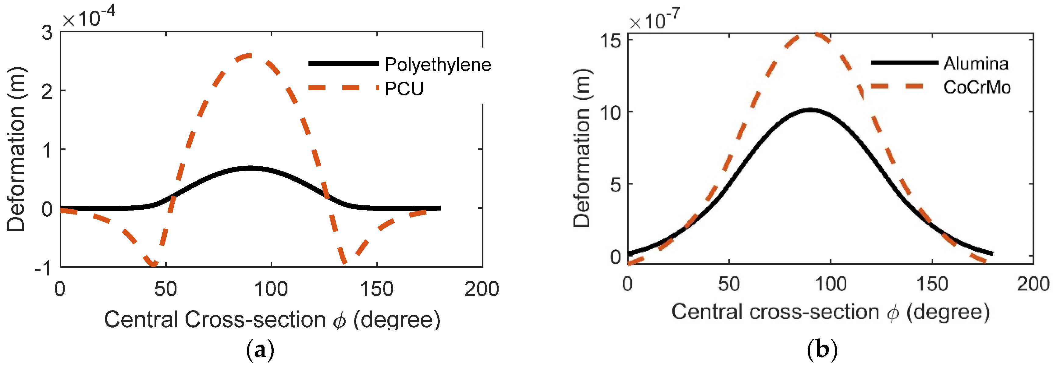
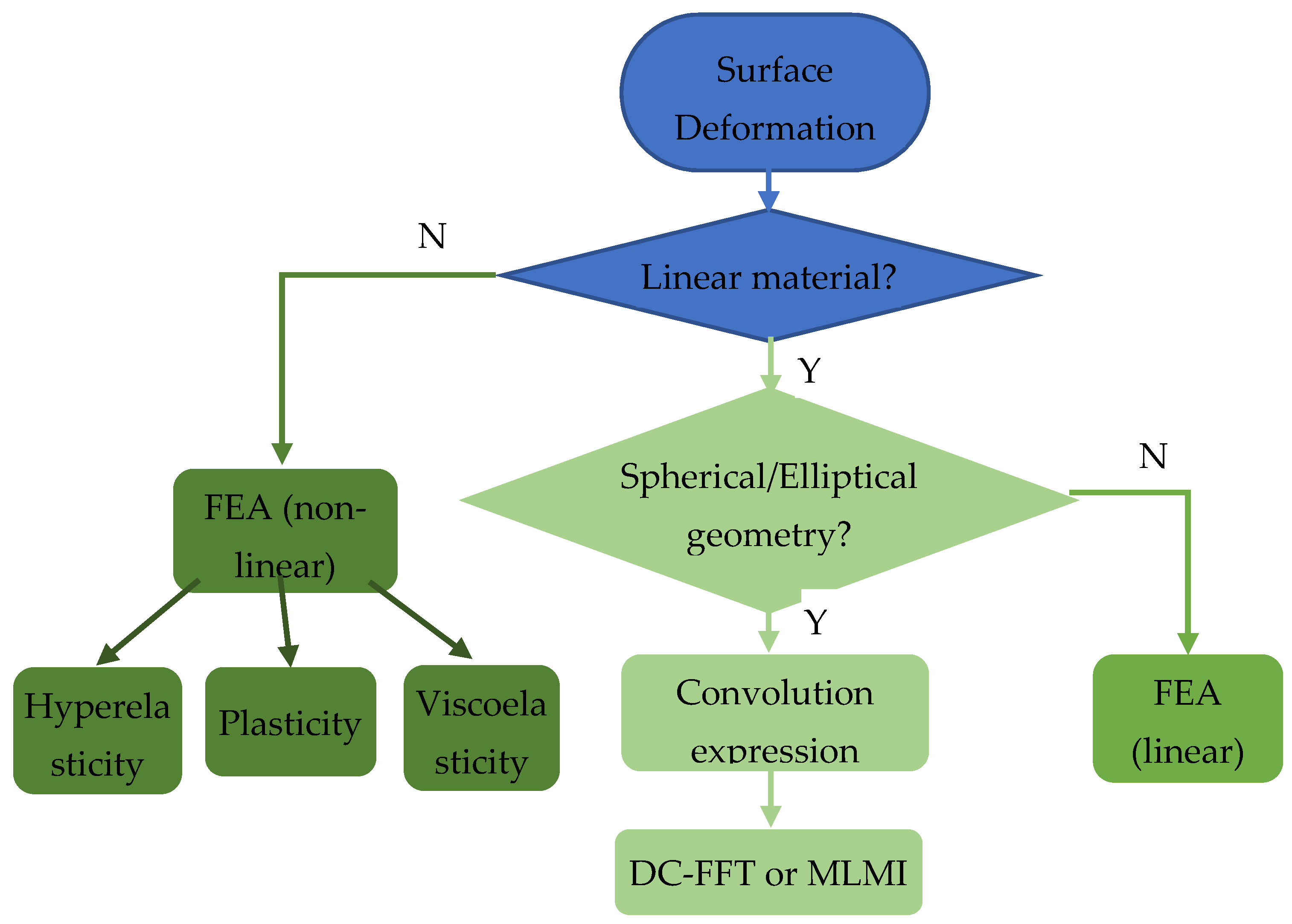
2.3. The Bearing Surface Deformations

EHL analysis of the artificial joints usually requires the elastic deformation calculation of the bearing surfaces. The maximum bulk surface deformation of hip and knee replacements is in an order of magnitude of 1–10 mm for hard-on-hard bearings and 10–100 mm for hard-on-soft pairs [52]. It is comparable to the film thickness and radial clearance; therefore, it cannot be ignored to define the fluid domain. The accuracy and efficiency of computing the deformation are challenges in EHL. It is part of the film thickness equation that is very sensitive to the nonlinear system, and it is coupled in the fluid–structure interactions and required thousands of times during the iteration of pressure when solving the fluid governing equations.
A simple constrained column model (or spring model) to calculate the elastic deformation of ball-in-socket, hard-on-soft bearings was originally developed by Bartel et al. [53] and adopted by a few EHL studies of hip and knee joint replacements [24,54,55], expressed as
δ = R [ ( R c o u t R c ) 3 1 ] E [ 1 1 2 ν + 2 1 + ν ( R c o u t R ) 3 ] p
δ is the elastic deformation; R and R c o u t are the inside and outside radii of the acetabular cup, respectively; E and ν are the elastic modulus and Poisson’s ratio of the cup, respectively.
This linear elastic model only considered the contribution of local pressure to the deformation for each certain point on the surface, ignoring the effect of pressures in the neighbourhood. It was mainly due to a lack of full-field analytical solutions for the structure deformation of the ball-in-socket model. This limitation was overcome by Jagatia and Jin [56] using the finite element method to calculate the elastic influence coefficients. Furthermore, Wang and Jin [52] developed a spherical fast Fourier transform method (SFFT) technique and improved the calculation efficiency significantly. In addition to the SFFT method, the multi-level multi-integration (MLMI) method was also adopted to accelerate the calculation [57].
Other approaches to solving the surface deformation coupled with the finite element analysis (FEA) [58,59,60,61]. It solves not only the contacting surface but also the whole structure domain. The Reynolds equation can be solved in a separate domain using the finite difference method or be set as a boundary condition of the structure problem. Lu et al. [62] proposed a viscoelastic model that addressed time delay response in the deformation of a polyethylene cup liner. The viscoelastic model combined two springs and a dashpot and was smoothly coupled in the EHL solving procedure.
Most previous studies on MoP hip joint lubrication modelling have assumed a linear elastic material property for polymers. However, some polymers exhibit hyperelastic behaviour subjected to the loading in hip or knee joints. The simplification in material properties allows the application of FFT and MLMI approached mentioned above to accelerate computing. The errors in deformations caused by the simplified linear models can be significant, for example, up to 50% for a soft PCU acetabular cup compared to a hyperelastic FEA model [49]. The bearing surface deformations of the cup (made of various soft and hard materials) are compared in Figure 5. The calculation is based on linear materials and pressure distribution with the maximum 10 MPa as described in Equation (5), which is a close shape to the EHL pressure solutions of the hip joint. The size of the cup was 14 mm for all cases, and all material properties can be seen in Table 3, apart from the elastic modulus of a specific polyethylene, which was 660 MPa. For hard-on-soft bearings pairs, deformation of the hard (head) component can be neglected as it is one to two orders of magnitude lower than that of the soft cup. For hard-on-hard bearings, deformations of both components need to be calculated in the EHL analysis.
p = p 0 · max [ 1 2 ( x R ) 2 2 ( z R ) 2 ,   0 ] ,   p 0 = 10 7   Pa
The speed, accuracy, and applicable geometries of the above approaches are summarised in Table 4. The speed and accuracy can only be roughly compared between these approaches due to the lack of the same mesh and operating conditions, particularly for the FEA method in the literature.

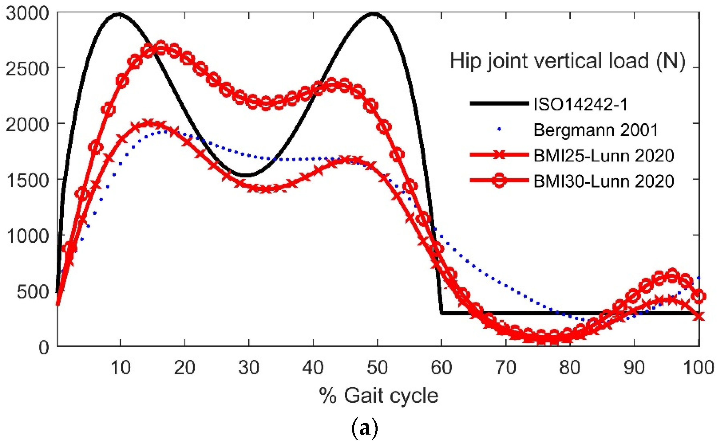
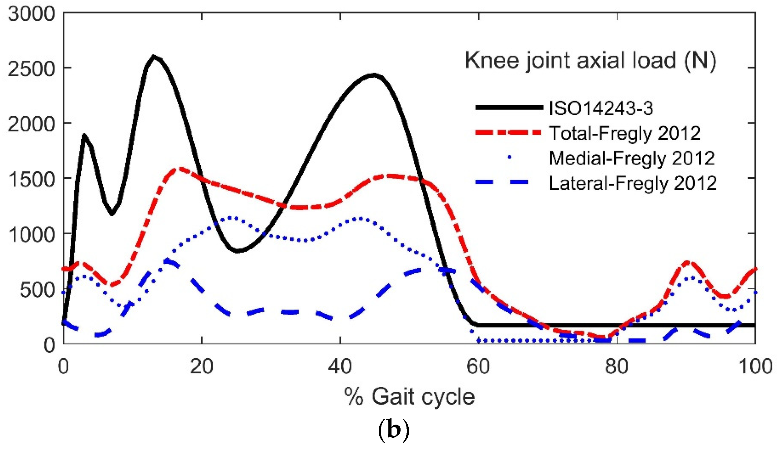
2.4. Loading and Motions of Human Daily Activities

Different kinds of gait patterns, such as walking, stair climbing, and running can be found in daily human activities. Both the natural and artificial joints undergo three-dimensional loads and motions in these activities. The normal walking cycle is the most often studied gait pattern among other activities. The international guidelines for wear simulators on joint loading and movements in walking cycles were published in ISO 14242-1 [64] and ISO 14243-3 [65] for human hip and knee joint replacements, respectively. For the hip joints, the loading form contains two peaks of 3 kN during the stance phase and a constant load of 300 N during the swing phase, based on a human model of 75 kg body weight. The displacement includes all three rotation directions.
A number of studies have investigated human daily activities in patients and various patient groups. The loading and motion of joints can be predicted using a musculoskeletal model based on the force reaction to the ground and displacement or acceleration of joints measured using motion caption. The patient characteristics, including body mass index (BMI), age, and gender, were investigated in the gait conditions [66,67,68,69]. Bergmann et al. [70] investigated nine different activities, including slow, normal, and fast walking, walking up and downstairs, standing up, sitting down, and knee bending. For example, the average peak hip contact forces ranged from 238% to 250% of body weight for slow, normal, and fast walking conditions. However, abnormal walking conditions such as unexpected stumbling can lead to extremely high contact forces in the hip joint [71]. The ISO14242-1 guide loading data on hip joints [64], measurements from patients by Bergmann et al. [70], and data from different patient groups of BMI by De Pieri et al. [67] are shown in Figure 6a.
For the knee joints, the ISO14243-3 guidelines provided a total axial load for the wear simulator test. Furthermore, in lubrication or contact models, the forces on the medial and lateral compartments are often investigated separately, such as predicted by Fregly et al. [72] and shown in Figure 6b.

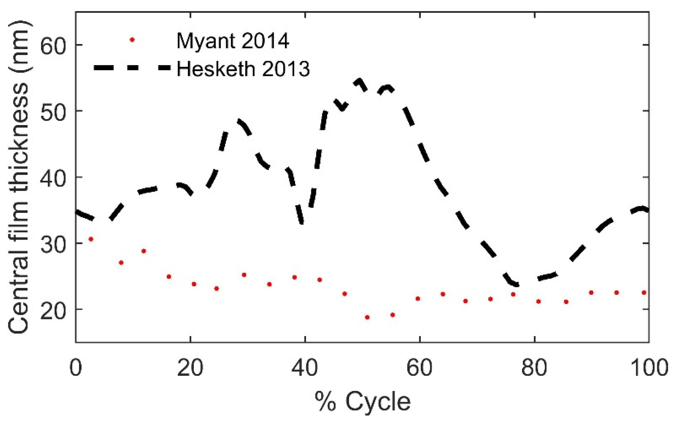
2.5. Measurement of Film Thickness

The in vivo measurement of the lubrication film thicknesses of artificial joints is very hard (if not impossible) to achieve at present. The related experiments were mostly carried out in in vitro environments, and they can provide direct validations to the numerical lubrication models.
An electrical resistivity technique was developed by Dowson’s group [73,74] to detect the extent of surface separation and the lubrication conditions. It was found that a mixed lubrication regime existed between the metal-on-metal bearing surfaces. With the substantial development of experimental techniques in the last decade, in vitro film thickness measurements have become possible for both the ball-on-disc and artificial joint simulators. The optical interferometry approach provides more accurate measurements of film thickness [8,75,76,77].
Cann’s research group at the Imperial College London [18,19,78,79,80] measured the lubricant films for both the bovine serum and other protein-containing solutions for metal femoral components sliding against a glass disc. It was found that the film formation did not follow the classical Newtonian EHL rules; the thicker film was found at the entrance; when the sliding speed increased, the film thickness decreased. A new lubrication mechanism called ‘protein aggregation lubrication (PAL)’ was proposed to describe the abnormal phenomenon.
Real geometries of artificial hip and knee joints have been considered in some designs of joint simulators using the colorimetric interferometry method to measure the in-situ film thickness and the effect of protein transport [9,40,81]. The results showed that the constant viscosity model did not agree well with the experimental measurements, and new rheology models describing the relationship between fluid viscosity and velocity were proposed. This will be discussed in the next section. Two groups [74,78] of measured film thickness in the literature are replotted in Figure 7. Myant and Cann’s experiment [78] adopted a 19 mm metal resurfacing cup, the ISO 14242-1 loading, and a full sinusoidal velocity with the maximum value at 20 mm/s, while Hesketh et al. [74] used an 18 mm metal cup and Leeds Prosim loading and motion format.

2.6. The Synovial Fluids and Rheology Models

Synovial fluids in human natural articular joints provide protection to the cartilage and transport nutrients and waste products between the synovium and cartilage. The protein components in synovial fluids are important to identify the rheological properties of the fluid, and they vary substantially between healthy joints and those with osteoarthritis or rheumatoid arthritis diseases, as well as between individual patients. After revision, the viscosity of synovial fluid was found lower than that at the primary TKR [82]. Alternative fluids often used for the in vitro friction and wear simulator test are bovine calf serum and deionised water. The bovine calf serum is recommended by the international standards for joint wear simulation test, and the concentration of protein is specified at 20 g/L for the knee wear test and 30 g/L for the hip wear test.
A simple model of the synovial fluid is the Newtonian fluid. It is reasonable when the shear rate is in a range of 10 6 ~ 10 7   s 1 during continuous walking conditions, and the corresponding viscosity is approximately 0.001   Pa · s , which is similar to water.
Both the synovial fluid and the bovine serum exhibit shear-thinning characteristics and their viscosities can be a few orders of magnitudes higher at low shear rate conditions [83]. Based on experimental measurements, a few studies proposed shear-thinning models derived from the Cross model [84], expressed as
η = η + η 0 η 1 + α ( γ ˙ ) β
where η 0   and   η note the viscosity at the zero and infinite shear rate; γ ˙ is the shear rate; α   and   β are parameters derived from a curve-fitting function based on experimental measurements. The viscosity and parameters in the above Cross model-based equations are summarised in Table 5.
Since the protein aggregation phenomenon was observed in the lubrication of the bovine serum, new rheology models were proposed. Myant et al. [18] firstly developed a power law relationship between an effective viscosity ( η ) and entrainment speed (u) derived from the measured film thickness, as shown in Equation (7).
η = 3.42241 u 1.24762
Lu et al. [9] proposed a new entrainment velocity–viscosity relation close to the Cross model as below, whose parameters were fitted from the film thickness curve as shown in Figure 8, measured using the ball and socket contact geometry.
η = η + η 0 η 1 + ( u / 0.175 ) 1.688
where η 0 = 0.352 Pa s; η = 0.038 Pa s.
In another rheology model proposed by Lee et al. [76], the protein transport was modelled using an aversion–diffusion equation to map concentration changes throughout the contact and particularly in the entrance zone. A scaling flow factor was introduced to limit the flow rate of protein transportation based on the inverse tangent function. As the fluid viscosity increases exponentially with the concentration of protein, the constitutive equation was expressed as
η = η p f ( η 0 η p f ) c  
η p f is the protein-free viscosity, c is the protein concentration.
Parameters of the fitted viscosity functions were calibrated using experimental measurements. The changes in concentration resulted in the film thickness being an order of magnitude thicker than expected in the classical EHL theory.

3. Mixed Lubrication Modelling of Hip and Knee Replacements

As discussed in Section 2, most lubrication modelling of artificial joints addressed the full film EHL regime rather than the mixed lubrication regime due to the complexity of the problem. However, when more practical conditions or implant designs are taken into account, it is necessary to develop mixed lubrication models. In this section, the specific lubrication regime ‘mixed lubrication’ and its numerical approaches applied to artificial joints are reviewed.

3.1. The Mixed Lubrication Regime

The mixed lubrication regime is a transient regime between the boundary lubrication and EHL as can be seen in the Stribeck curve [87]. Theoretically, the mixed lubrication regime can be determined by the λ ratio, a ratio of the film thickness to the root-mean-square (RMS) surface roughness of the two frictional surfaces. When 1 < λ < 3 the lubrication condition is considered the mixed lubrication. For example, the RMS surface roughness of the MoP joint implants is in the range of 0.1–2 µm [35,37,42], and the roughness can change either slightly or significantly during wear [88,89]. To maintain the full film lubrication, the minimum film thickness must be beyond 0.3–6 µm, which is generally not the case in actual physiological conditions.

3.2. The Mixed Lubrication Models

Three types of mixed lubrication methods have been developed for general engineering problems. The applications of these methods in artificial joint lubrication modelling are presented in the following sections.

3.2.1. Deterministic Model

The deterministic model distinguishes asperity contacts from full film lubrication explicitly. A uniform Reynolds equation to describe the fluid flow was proposed by Hu and Zhu [90]; in the Cartesian coordinate system, it can be expressed as
x ( h 3 12 η   p x ) + y ( h 3 12 η   p y ) =                         u h x +                                       h t                                                         Poiseuille   flow                                           Couette   flow           transient   term
where x , y , z are Cartesian coordinates; u and v are the entrainment velocities at the x and y directions, respectively; h is the film thickness; p is the fluid pressure; η is the dynamic viscosity of the Newtonian fluid, and t is time. When the calculated film thickness is below a certain boundary film thickness, indicating the asperity contact occurs, the Poiseuille flow (the left-hand side terms in the Reynolds equation) driven by the fluid pressure gradient is cut off because no hydrodynamic pressure is established, and the Couette flow (the first term at the right-hand side) and the transient term h t are left over. The truncated equation is expressed as
u h x + h t = 0
The deterministic approach can obtain detailed information about the local asperity contact, such as contact boundaries and local pressure distributions. In other words, the lubrication condition is determined at each discrete mesh grid in the calculation domain. It generally takes more computing resources and a longer time. The numerical convergence is more challenging than the stochastic method discussed in Section 3.2.2.
Gao et al. studied the mixed lubrication problem of the artificial hip [32,34,49,91,92] and knee [55] replacements using the deterministic models. The mixed lubrication model has been further extended to wear models [34,92] in which the local film thickness and roughness were introduced to the Archard wear law to address the mixed lubrication. The involvement of lubrication distinguished the wear model from other dry-contact wear models [93]. A typical two-stage (bedding-in and steady-state) wear trend was predicted which was observed in the joint wear simulator testing.
Marian et al. [40] developed a mixed EHL model of knee replacements. In this deterministic model, the asperity contact pressure was calculated by a statistical Greenwood-Williamson model with implementation in MathWorks MATLAB. Asperity contact was only observed when the artificial synovial fluid (with the plateau viscosity of 0.002 Pa·s) was simulated. The contact geometry of the knee components was represented by multiple radii of elliptic contacts in both medial-lateral and anterior-posterior directions. The non-Newtonian fluid behaviour and thermal effect were also taken into account. The predicted film thickness in some cases was validated by the fluorescent measurements.
Ruggiero and Sicilia [94,95] proposed a similar mixed EHL model as Gao et al. [92] for hip replacements. The asperity contact regime was determined by the negative film thickness during numerical calculations, and the asperity contact pressure was calculated by applying the Hertzian contact theory to the local contact area. This model was extended to predict the wear in a similar way as [92], which involved the λ ratio in the wear factor of the Archard wear law. The asperity contact was observed during the gait cycles.
Another study on the wear modelling of MoP hip joints adopted mixed lubrication in which the asperity contact was based on the Winkler elastic foundation model [96]. However, details of the film thickness or pressure distribution were not presented in their results.

3.2.2. Stochastic Models

The stochastic model, also known as the average flow or homogeneous model, involves the influence of surface profile on the flow by introducing flow factors to the Reynolds equation, firstly proposed by Patir and Cheng [97] in 1978, expressed as
x ( φ x h 3 12 η   p x ) + y ( φ y h 3 12 η   p y ) = U 1 + U 2 2 h x + U 1 U 2 2 σ φ s x + h t
where φ x ,   φ y are pressure flow factors; φ s is the shear flow factor; σ is the standard deviation of the combined surface roughness; U 1 , U 2 are surface velocities in the x-direction. When the film thickness is much larger than the surface roughness, the pressure flow factors are approaching 1, and the equation is close to the classic Reynolds equation.
The flow factors are determined by the stochastic parameters of surface roughness or textured profile. The advantage of the stochastic models is the efficient computing and numerical stability to obtain the converged solution. However, it cannot provide details at the asperity contact area, such as local pressure and film thickness distributions. Instead, it gives an average pressure and film thickness distribution in the whole calculation domain.
Chyr et al. [98] investigated the effect of surface texturing on MoP hip replacements using the stochastic hydrodynamic lubrication models to predict the lubricant film and load-carrying capacity. The geometry was simplified as a ball-on-plane model and no elastic deformation was involved. With dimpled surface patterns on the metal femoral head, the load-carrying capacity was increased.
Recently Butt et al. [99] proposed a mixed lubrication model for knee implants based on a stochastic model of surface roughness. The real surface curvature was addressed instead of simplified elliptical geometry and multiple contact areas were found in a single tibia insert condyle, as shown in Figure 9. It elucidates the importance of considering the real contact geometry in lubrication modelling.

3.2.3. Homogenisation Methods

One important limitation of the deterministic methods is the tremendous amount of computer memory and central processing unit (CPU) time required since very fine mesh grids are required to capture the geometric variation of the surface roughness. One solution to this limitation may be the homogenisation methods. The effects of the surface roughness are taken into account during the calculation of a local problem in a periodic system, resulting in lower computing costs.
Significant contributions to the applications of the homogenisation methods in lubrication modelling were made by Almqvist and his co-authors [100,101,102,103]. It has also been successfully applied to solve mixed lubrication problems. Sahlin et al. [104,105] developed a two-scale model to simulate mixed lubrication conditions considering arbitrary deterministic surface roughness measurements as input. In their model, the rough surface deformation of the partial contact problem was calculated with an algorithm based on discrete convolution fast Fourier transform (DC-FFT), and a method based on homogenisation was used to calculate flow factors for all lubrication regimes. The mixed lubrication model was validated by comparing it with the flow measurements for three test specimens with different rough surfaces. The results indicated that the model could be a good numerical tool for tribological components operating in all lubrication regimes.
Another set of homogenisation methods is based on the heterogeneous multiscale method (HMM), which is a general flexible framework in the sense that global and local-scale models do not need to be of the same nature. This approach was first proposed by Gao and Hewson [106] to analyse the effect of surface texture on lubricating problems. The pressure gradient d p d x is a homogenised function of the pressure (p), mass flow rate (q), and the gap (g), obtained by curve-fitting solutions of a series of small-scale simulations. In the one-dimensional case, the equation can be written as
d p d x = f ( g ,   p ,   q )
g is the gap; p is pressure, q is mass flow rate.
Then, the pressure gradient equation is solved together with the mass conservation equation
d q d x = 0
Although no mixed lubrication regimes have been simulated using this approach, the HMM is still very promising to simulate the mixed lubrication in joint replacements since the surface texture and topography have been successfully modelled using this approach [107].
More details on the main characteristics of the mixed lubrication models of hip and knee implants are summarised in Table 6. Some results of the film thickness and pressure from previous studies are compared in Figure 10 and Figure 11 for hip and knee implants, respectively. It needs to be noted that the materials, geometry, loading, and motion conditions were not all the same among these studies, so the aim of presenting the results in one figure is to give readers a clue of the trend and range of the results, not to compare the results quantitively.

4. Discussion

Lubrication modelling of human artificial joints has been investigated in the past 40 years since the pioneering studies by Prof Duncan Dowson. The level of complexity of the numerical models has gradually increased with more realistic factors being taken into account. However, there are still challenges in accurately predicting the lubrication performance of the artificial hip and knee joints. The contact geometry and materials of joint implants, the synovial fluid, as well as a limited understanding of the mixed lubrication theory, contribute to more complexity to the problem than general industrial applications.

4.1. The Mixed Lubrication Theory

A new mixed lubrication model needs to address the following two key questions.
(1)
Is the negative film thickness proper to determine the asperity contact?
As reviewed in Section 3, the asperity contact zone is mostly determined when a negative film thickness occurs, or the calculated film thickness goes below a small value representing the boundary film. Theoretically, the calculated film thickness can always be positive if the mesh grid is fine enough. Negative film thicknesses are rarely seen in EHL simulations of industrial bearing components. However, it has been found in the modelling of artificial joints even with the assumption of smooth surfaces. This is because the contact area of hip or knee replacements is much larger than that of the industrial bearings (about 5–10 mm VS 1 mm of contact diameters). Furthermore, the calculation domain only covers a small area around the contact zone for industrial bearings, but it includes the entire contacting surface for the hip or knee joints due to the nature of conforming contact.
For example, if the same mesh grid 256 × 256 is used in the EHL models, the real size represented by one mesh element (approximately as a rectangle) is 220 µm in a ball-in-socket hip joint model (calculation based on an inner cup radius of 18 mm). However, the mesh size is about 5.8 µm for an industrial point-contact bearing (calculation based on a ball radius of 19.05 mm and loading of 800 N) [108]. In other words, the mesh is about 40 times denser in an industrial bearing EHL model than that used in a hip implant EHL model. Thus, the negative film thickness can be avoided in such a dense mesh.
In the smooth surface cases, the negative film thickness is mainly a result of numerical inaccuracy due to the coarse mesh grid, and it is not a rigorous explanation of the physical film rupture. The validation of EHL models of artificial joints needs to be highlighted by experimental measurements of asperity contact pressure and film thickness.
The mesh density is also a severe limitation in describing the local surface roughness or textured profiles of joint implants. An increase in the mesh grids will lead to significant computing costs of surface deformation, as also discussed in the subsection below. Uneven distribution of EHL mesh grids could be a solution to balance the computing efficiency and accuracy.
(2)
Is the unified Reynolds equation adequate to solve the micro-EHL problems?
For the deterministic models, there is a debate on if the unified mixed lubrication model using a reduced Reynolds equation is appropriate to solve the micro-EHL problem [109,110]. When the calculated film thickness is below a small value, the Reynolds equation is truncated by removing the Poiseuille flow and only keeping the Couette flow; the local film thickness is artificially set to a small value when it goes below that value; the local contact pressure is derived from the film thickness equation. This treatment physically represents the flow driven by sliding motion only (no pressure gradient driven). However, it can result in numerically inaccurate film thickness. The recent development of the unified model for industrial engineering problems has proposed new solutions to improve the numerical accuracy by ensuring continuous pressure boundary conditions and allowing more iterations when deciding the film thickness is lower than the small value [108]. The unified model with improved pressure boundary conditions works well when the surface roughness is relatively low (below 1 µm). However, it is still limited when applying to hip or knee implants in which the surface roughness, wear depth, or depth of surface dimples are in the range of 1–100 µm [34,55]. Thus, a better-mixed lubrication model is required to describe the discontinuous flow at the asperity contact area and wear (or textured) dimples.
The stochastic models can avoid answering the questions on local asperity contacts and provide the prediction of average film thickness. It is useful to compare different designs or operating conditions pressure focusing on their lubrication performance. However, the obvious advantage of the deterministic model is the ability to provide local information on asperity contact, hydrodynamic pressure, and film thickness, which is important to further prediction of wear, particularly the wear scar development during long-term cycles.
A multiscale mixed lubrication method combining a stochastic flow and the small-scale asperity contact could be a promising way to address the problem. The load partition calculation and its variation due to surface profile changes in long-term wear could be a challenge in this type of method.

4.2. Methods to Address the Realistic Geometry, Design, and Materials

New materials and designs have raised new challenges in the EHL modelling of artificial joints. The soft materials, including UHMWPE, HXLPE, and PCU are generally non-linear materials exhibiting hyperelastic and viscoelastic properties. However, in most studies, only the linear elastic structure deformation of these materials was addressed to avoid an expensive computing cost in the EHL simulation. In future studies, hyperelastic models, such as Yeoh and Mooney–Rivlin models, can be introduced into the calculation of surface deformations.
An illustration of the approaches for the calculation of surface deformations is shown in Figure 12. The most efficient approach includes the DC-FFT and MLMI methods. These methods are applicable only if two conditions are satisfied; (i) the contact geometry can be presented as a spherical or elliptical contact; (ii) the solid material is linear-elastic and isotropic. If these conditions cannot be satisfied, for example, when a real geometry of knee implants or non-linear materials are considered, a simple column model or a complicated FEA model is used, which sacrifices either the numerical accuracy or computing efficiency. Thus, the calculation of surface deformation is one of the major challenges in the EHL modelling of artificial joints to be solved in future studies. It is necessary to couple the lubrication model, which is often solved by in-house code with the structure deformation solved using FEA commercial packages. A substitute model using machine learning technology could be a potential solution to efficiently solve the complex geometry and materials [111,112,113].
The contact geometry of knee condyles was often described as an elliptical contact, which led to a single contact zone on each condyle surface. However, the actual geometry for some designs of the knee joint has demonstrated multiple contact zones on one condyle, which has highlighted the importance of using real surface geometry instead of a simplified one [99,114].

4.3. Individual Physiological Diversities

The physiological properties, including the synovial fluid properties, daily activities, bone and muscle mechanical/geometrical properties, and body mass index vary between individuals and can even change after the joint replacement operation. As the concept of customised joint implants has been proposed, the future EHL model needs to address the individual diversities to better serve the new requirements.
In order to select the proper physiological properties in the EHL model, the objective of modelling must be clearly stated. For example, If the model aims to simulate the performance of implant samples in a joint simulator testing, the lubricant should be the bovine calf serum or deionised water, and the loading and motion data should follow the gait cycles described by the ISO documents. If the bovine serum is used, the protein aggregation effect needs to be considered; while for the deionised water, the non-Newtonian or protein aggregation properties can be ignored. The numerical solutions should be validated by the experimental joint simulator testing accordingly.
The coupling between lubrication and biomechanics is an important aspect to be addressed in future studies. Current models rely on the input of the loading and motion during activity. However, interactions between joint kinematics and biomechanics of the whole body system, including muscles and surrounding tissues, can be simulated using a multibody dynamics musculoskeletal model [115]. If the model aims to simulate the implant performance in an individual or a specific group, the parameters need to be reasonably defined based on experimental measurements for model validation.
In vivo measurements [69,116,117] of hip and knee joint contact forces have been made in patients with an electrical sensor integrated into the implant. It emphasizes the variety of individuals and activities. The combination of daily activities is important to accurately predict the lubrication performance of hip and knee joint replacements.

4.4. Lubrication Analysis towards Design Optimisation

The major objective of performing lubrication analysis in hip and knee joint replacements is to improve the design and the lifetime of the prostheses. Although most improvements in materials rely on experimental wear testing, lubrication analysis has contributed to the design parameters, including the size of the components, clearance, surface profile, and surface texture. The research group led by Prof John Fisher has proposed a non-spherical Alpharabolar cup design that enables better lubrication and significant reduction of wear up to 80% for the hip implant. The prediction of lubrication performance and the optimisation of geometrical parameters provided evidence for the design. This new design was adopted by one of the major orthopaedic device manufacturers DePuy Synthes and the aSphere® M-Spec series hip implant was released in 2009.
Surface texturing is a state-of-the-art technology to improve the tribological performance of industrial bearings by manufacturing micro dimples or patterns on the bearing surfaces. Its application in hip or knee joint implants has attracted a lot of attention [50,75,118,119,120]. The friction reduction is the main benefit of the textured surface for an engineering bearing which often operates at high speed, so heat generation is a big issue. However, when considering a hip or knee joint bearing, the major issue is not friction but lubrication and wear. A textured surface cannot always guarantee improvement of lubrication, particularly in the mixed lubrication regime, and for the hard-on-soft bearing pairs [32,55]. Thus, deliberate optimisation is required to obtain the best performance.

4.5. Joint Simulators and Validation of Numerical Models

The developed experimental technique has made the validation of numerical lubrication models possible, especially when the actual geometries and loading conditions are taken into account. As reviewed in Section 2.4, in vitro experimental measurement of the lubricant film thickness can provide direct validation for the numerical models [9,73] and can be used to calibrate parameters in lubrication models, such as constants in the viscosity constitutive equation [76,121]. However, there are some challenges or limitations in terms of the geometries of contact bodies and materials. The electrical resistance approach is not accurate enough to measure nanoscale film thickness and it is limited in ball-on-plate contacts. The optical interferometry approach is more accurate and applicable to ball-in-socket contact geometries. However, it requires one of the contact bodies to be made of glass to allow light transmission and interferometry measurements.
Hip and knee joint simulators are important devices to test the tribological performance of joint replacements. They are designed to mimic walking under physiological loading and motion conditions, particularly walking cycles. Some joint simulators have the function to measure the film thickness, but most of the others are mainly used to predict the wear performance of the hip and knee joint replacements during short- or long-term operation. Results from wear simulator testing can provide indirect validations to the lubrication models. For example, the tested friction coefficient [28], wear path, and wear rate [16] can be compared with results derived from lubrication models.

5. Conclusions

The first reference to study the lubrication problem of a hip joint replacement was published by Dowson in 1966 [15]. Since then, many studies have contributed to this research area, and important findings with a focus on the lubrication and mixed lubrication theory, lubrication mechanism, and simulation methods were reviewed in this paper. The development of lubrication modelling methodology is presented mainly in five areas: the geometry of bearing components, the materials and their deformation, the synovial fluids as lubricants, the loading, and motion.
Accuracy and efficiency are still two challenges in the EHL model of joint replacements. However, there are also other challenges, including the mixed lubrication theory, the numerical complexities due to more realistic geometry, material and rheology, and individual physiological diversities. Some lubrication models that are well used in industrial engineering applications are not applicable or have limitations when applied to hip or knee joint replacements, such as approaches to accelerate the calculation of surface deformation cannot be directly used in the complicated knee joint contact geometries. The challenge to predicting the lubrication using numerical simulations also lies in the coupling of surface deformation in lubrication, a multiscale between the bearing geometry and surface profiles, and the limitation of the Reynolds equation governing fluid flow. Previous studies have provided a good understanding of the lubrication characteristics of joint replacements. Although challenges in the lubrication theory and numerical methods need to be addressed, future studies should aim not just to analyse but also to design—to promote lubrication, reduce wear, and prolong the lifetime of hip and knee replacements.

Author Contributions

Conceptualization, all; formal analysis, all.; resources, all; writing—original draft preparation, all; writing—review, revision and editing, L.G.; project administration, Z.J.; funding acquisition, Z.J. All authors have read and agreed to the published version of the manuscript.

Funding

This work is financially supported by the National Natural Science Foundation of China No. 52035012.

Data Availability Statement

Not applicable.

Conflicts of Interest

The authors declare no conflict of interest.

References

  1. National Joint Registry. National Joint Registry the 18th Annual Report; National Joint Registry: London, UK, 2021. [Google Scholar]
  2. Evans, J.T.; Walker, R.W.; Blom, A.W.; Whitehouse, M.R.; Sayers, A. How long does a hip replacement last? A systematic review and meta-analysis of case series and national registry reports with more than 15 years of follow-up. Lancet 2019, 393, 647–654. [Google Scholar] [CrossRef]
  3. Revell, P.A. The combined role of wear particles, macrophages and lymphocytes in the loosening of total joint prostheses. J. R. Soc. Interface 2008, 5, 1263–1278. [Google Scholar] [CrossRef]
  4. Dowson, D. Review Paper 2: Whither Tribology? Proc. Inst. Mech. Eng. Conf. Proc. 1969, 184, 181–185. [Google Scholar] [CrossRef]
  5. Dowson, D.; Wright, V. Bio-tribology. In The Rheology of Lubricants; Davenport, T.C., Ed.; Applied Science Publishers: Barking, UK, 1973; pp. 81–88. [Google Scholar]
  6. Dowson, D.; Jin, Z.-M. Metal-on-metal hip joint tribology. Proc. Inst. Mech. Eng. Part H J. Eng. Med. 2006, 220, 107–118. [Google Scholar] [CrossRef] [PubMed]
  7. Hamrock, B.J.; Dowson, D. Elastohydrodynamic Lubrication of Elliptical Contacts for Materials of Low Elastic Modulus I—Fully Flooded Conjunction. J. Lubr. Technol. 1978, 100, 236–245. [Google Scholar] [CrossRef]
  8. Nečas, D.; Vrbka, M.; Rebenda, D.; Gallo, J.; Galandáková, A.; Wolfová, L.; Křupka, I.; Hartl, M. In situ observation of lubricant film formation in THR considering real conformity: The effect of diameter, clearance and material. J. Mech. Behav. Biomed. Mater. 2017, 69, 66–74. [Google Scholar] [CrossRef] [PubMed]
  9. Lu, X.; Nečas, D.; Meng, Q.; Rebenda, D.; Vrbka, M.; Hartl, M.; Jin, Z. Towards the direct validation of computational lubrication modelling of hip replacements. Tribol. Int. 2020, 146, 106240. [Google Scholar] [CrossRef]
  10. Dowson, D.; Higginson, G.R. A Numerical Solution to the Elasto-Hydrodynamic Problem. J. Mech. Eng. Sci. 1959, 1, 6–15. [Google Scholar] [CrossRef]
  11. Hamrock, B.J.; Dowson, D. Isothermal Elastohydrodynamic Lubrication of Point Contacts: Part III—Fully Flooded Results. J. Lubr. Technol. 1977, 99, 264–276. [Google Scholar] [CrossRef]
  12. Hamrock, B.J.; Dowson, D. Isothermal Elastohydrodynamic Lubrication of Point Contacts: Part 1—Theoretical Formulation. J. Lubr. Technol. 1976, 98, 223–228. [Google Scholar] [CrossRef]
  13. Hamrock, B.J.; Dowson, D. Isothermal Elastohydrodynamic Lubrication of Point Contacts: Part II—Ellipticity Parameter Results. J. Lubr. Technol. 1976, 98, 375–381. [Google Scholar] [CrossRef]
  14. Hamrock, B.J.; Dowson, D. Isothermal Elastohydrodynamic Lubrication of Point Contacts: Part IV—Starvation Results. J. Lubr. Technol. 1977, 99, 15–23. [Google Scholar] [CrossRef]
  15. Dowson, D. Paper 12: Modes of Lubrication in Human Joints. Proc. Inst. Mech. Eng. Conf. Proc. 1966, 181, 45–54. [Google Scholar] [CrossRef]
  16. Dowson, D. Tribological principles in metal-on-metal hip joint design. Proc. Inst. Mech. Eng. Part H J. Eng. Med. 2006, 220, 161–171. [Google Scholar] [CrossRef] [PubMed]
  17. Nečas, D.; Vrbka, M.; Rebenda, D.; Gallo, J.; Galandáková, A.; Wolfová, L.; Křupka, I.; Hartl, M. In situ observation of lubricant film formation in THR considering real conformity: The effect of model synovial fluid composition. Tribol. Int. 2018, 117, 206–216. [Google Scholar] [CrossRef]
  18. Myant, C.; Cann, P. In contact observation of model synovial fluid lubricating mechanisms. Tribol. Int. 2013, 63, 97–104. [Google Scholar] [CrossRef]
  19. Myant, C.; Cann, P. On the matter of synovial fluid lubrication: Implications for Metal-on-Metal hip tribology. J. Mech. Behav. Biomed. Mater. 2014, 34, 338–348. [Google Scholar] [CrossRef] [PubMed]
  20. Fan, J.; Myant, C.W.; Underwood, R.; Cann, P.M.; Hart, A. Inlet protein aggregation: A new mechanism for lubricating film formation with model synovial fluids. Proc. Inst. Mech. Eng. Part H J. Eng. Med. 2011, 225, 696–709. [Google Scholar] [CrossRef]
  21. Liu, F.; Wang, F.C.; Jin, Z.M.; Hirt, F.; Rieker, C.; Grigoris, P. Steady-state elastohydrodynamic lubrication analysis of a metal-on-metal hip implant employing a metallic cup with an ultra-high molecular weight polyethylene backing. Proc. Inst. Mech. Eng. Part H J. Eng. Med. 2004, 218, 261–270. [Google Scholar] [CrossRef] [PubMed]
  22. Wang, F.C.; Liu, F.; Jin, Z.M. A general elastohydrodynamic lubrication analysis of artificial hip joints employing a compliant layered socket under steady state rotation. Proc. Inst. Mech. Eng. Part H J. Eng. Med. 2004, 218, 283–291. [Google Scholar] [CrossRef]
  23. Jin, Z.M.; Dowson, D. A full numerical analysis of hydrodynamic lubrication in artificial hip joint replacements constructed from hard materials. Proc. Inst. Mech. Eng. Part C J. Mech. Eng. Sci. 1999, 213, 355–370. [Google Scholar] [CrossRef]
  24. Jalali-Vahid, D.; Jagatia, M.; Jin, Z.; Dowson, D. Prediction of lubricating film thickness in UHMWPE hip joint replacements. J. Biomech. 2001, 34, 261–266. [Google Scholar] [CrossRef]
  25. Jalali-Vahid, D.; Jagatia, M.; Jin, Z.M.; Dowson, D. Prediction of lubricating film thickness in a ball-in-socket model with a soft lining representing human natural and artificial hip joints. Proc. Inst. Mech. Eng. Part J J. Eng. Tribol. 2001, 215, 363–372. [Google Scholar] [CrossRef]
  26. Dowson, D.; Hardaker, C.; Flett, M.; Isaac, G.H. A hip joint simulator study of the performance of metal-on-metal joints: Part II: Design. J. Arthroplast. 2004, 19, 124–130. [Google Scholar] [CrossRef]
  27. Okazaki, Y. Effect of head size on wear properties of metal-on-metal bearings of hip prostheses, and comparison with wear properties of metal-on-polyethylene bearings using hip simulator. J. Mech. Behav. Biomed. Mater. 2014, 31, 152–163. [Google Scholar] [CrossRef]
  28. Wang, F.C.; Brockett, C.; Williams, S.; Udofia, I.; Fisher, J.; Jin, Z.M. Lubrication and friction prediction in metal-on-metal hip implants. Phys. Med. Biol. 2008, 53, 1277–1293. [Google Scholar] [CrossRef] [PubMed]
  29. Wang, F.C.; Zhao, S.X.; Quiñonez, A.F.; Xu, H.; Mei, X.S.; Jin, Z.M. Nonsphericity of bearing geometry and lubrication in hip joint implants. J. Tribol. 2009, 131, 31201. [Google Scholar] [CrossRef]
  30. Wang, L.; Liu, X.; Li, D.; Liu, F.; Jin, Z. Contact mechanics studies of an ellipsoidal contact bearing surface of metal-on-metal hip prostheses under micro-lateralization. Med Eng. Phys. 2014, 36, 419–424. [Google Scholar] [CrossRef]
  31. Fisher, J. Acetabular. Cup. Patent WO 95/23566, 8 September 1995. [Google Scholar]
  32. Gao, L.M.; Meng, Q.E.; Liu, F.; Fisher, J.; Jin, Z.M. The effect of aspherical geometry and surface texturing on the elastohydrodynamic lubrication of metal-on-metal hip prostheses under physiological loading and motions. Proc. Inst. Mech. Eng. Part C J. Mech. Eng. Sci. 2010, 224, 2627–2636. [Google Scholar] [CrossRef]
  33. Meng, Q.; Gao, L.; Liu, F.; Yang, P.; Fisher, J.; Jin, Z. Contact mechanics and elastohydrodynamic lubrication in a novel metal-on-metal hip implant with an aspherical bearing surface. J. Biomech. 2010, 43, 849–857. [Google Scholar] [CrossRef] [Green Version]
  34. Gao, L.; Hua, Z.; Hewson, R. Can a ‘pre-worn’ bearing surface geometry reduce the wear of metal-on-metal hip replacements?—A numerical wear simulation study. WEAR 2018, 406, 13–21. [Google Scholar] [CrossRef]
  35. Mattei, L.; Di Puccio, F.; Piccigallo, B.; Ciulli, E. Lubrication and wear modelling of artificial hip joints: A review. Tribol. Int. 2011, 44, 532–549. [Google Scholar] [CrossRef]
  36. Chan, F.W.; Bobyn, J.D.; Medley, J.B.; Krygier, J.J.; Tanzer, M. The Otto Aufranc Award—Wear and lubrication of metal-on-metal hip implants. Clin. Orthop. Relat. Res. 1999, 369, 10–24. [Google Scholar] [CrossRef] [PubMed]
  37. Jin, Z.M. Theoretical studies of elastohydrodynamic lubrication of artificial hip joints. Proc. Inst. Mech. Eng. Part J J. Eng. Tribol. 2006, 220, 719–727. [Google Scholar] [CrossRef]
  38. Roussot, M.A.; Haddad, F.S. The evolution of patellofemoral prosthetic design in total knee arthroplasty: How far have we come? EFORT Open Rev. 2019, 4, 503–512. [Google Scholar] [CrossRef] [PubMed]
  39. Zhang, Q.; Chen, Z.; Jin, Z.; Muratoglu, O.K.; Varadarajan, K.M. Patient-specific musculoskeletal models as a framework for comparing ACL function in unicompartmental versus bicruciate retaining arthroplasty. Proc. Inst. Mech. Eng. Part H J. Eng. Med. 2021, 235, 861–872. [Google Scholar] [CrossRef]
  40. Marian, M.; Orgeldinger, C.; Rothammer, B.; Nečas, D.; Vrbka, M.; Křupka, I.; Hartl, M.; Wimmer, M.A.; Tremmel, S.; Wartzack, S. Towards the understanding of lubrication mechanisms in total knee replacements—Part II: Numerical modeling. Tribol. Int. 2021, 156, 106809. [Google Scholar] [CrossRef]
  41. Su, Y.; Fu, Z.; Yang, P.; Wang, C. A Full Numerical Analysis of Elastohydrodynamic Lubrication in Knee Prosthesis under Walking Condition. J. Mech. Med. Biol. 2010, 10, 621–641. [Google Scholar] [CrossRef]
  42. Di Puccio, F.; Mattei, L. Biotribology of artificial hip joints. World J. Orthop. 2015, 6, 77–94. [Google Scholar] [CrossRef]
  43. Inagaki, K.; Iida, S.; Miyamoto, S.; Suzuki, C.; Nakatani, T.; Shinada, Y.; Kawarai, Y.; Hagiwara, S.; Nakamura, J.; Orita, S.; et al. Natural history of noise and squeaking in cementless ceramic-on-ceramic total hip arthroplasty. J. Orthop. 2020, 21, 544–549. [Google Scholar] [CrossRef]
  44. Jin, Z.; Zheng, J.; Li, W.; Zhou, Z. Tribology of medical devices. Biosurface Biotribol. 2016, 2, 173–192. [Google Scholar] [CrossRef]
  45. Dowson, D. Elastohydrodynamic lubrication in ‘soft-on-soft’ natural synovial joints; ‘hard-on-soft’ cushion and ‘hard-on-hard’ metal-on-metal total joint replacements. In Proceedings of the IUTAM Symposium on Elastohydrodynamics and Micro-elastohydrodynamics, Cardiff, UK, 1–3 September 2004; Springer: Dordrecht, The Netherlands, 2006; pp. 297–308. [Google Scholar]
  46. Ebramzadeh, E.; Campbell, P.A.; Takamura, K.M.; Lu, Z.; Sangiorgio, S.N.; Kalma, J.J.; De Smet, K.A.; Amstutz, H.C. Failure Modes of 433 Metal-on-Metal Hip Implants: How, Why, and Wear. Orthop. Clin. N. Am. 2011, 42, 241–250. [Google Scholar] [CrossRef] [PubMed]
  47. Dowson, D.; Fisher, J.; Jin, Z.M.; Auger, D.D.; Jobbins, B. Design Considerations for Cushion Form Bearings in Artificial Hip Joints. Proc. Inst. Mech. Eng. Part H J. Eng. Med. 1991, 205, 59–68. [Google Scholar] [CrossRef] [PubMed]
  48. Meng, Q.; Wang, J.; Yang, P.; Jin, Z.; Fisher, J. The lubrication performance of the ceramic-on-ceramic hip implant under starved conditions. J. Mech. Behav. Biomed. Mater. 2015, 50, 70–76. [Google Scholar] [CrossRef]
  49. Ford, A.; Hua, Z.; Ferguson, S.J.; Pruitt, L.A.; Gao, L. A 3D-transient elastohydrodynamic lubrication hip implant model to compare ultra high molecular weight polyethylene with more compliant polycarbonate polyurethane acetabular cups. J. Mech. Behav. Biomed. Mater. 2021, 119, 104472. [Google Scholar] [CrossRef]
  50. Ren, S.; Huang, J.; Cui, M.; Pu, J.; Wang, L. Improved adaptability of polyaryl-ether-ether-ketone with texture pattern and graphite-like carbon film for bio-tribological applications. Appl. Surf. Sci. 2017, 400, 24–37. [Google Scholar] [CrossRef]
  51. Cacopardo, L. Biomaterials for orthopedic devices. In Human Orthopaedic Biomechanics; Innocenti, B., Galbusera, F., Eds.; Elsevier: Amsterdam, The Netherlands, 2022; p. 345. [Google Scholar]
  52. Wang, F.C.; Jin, Z.M. Prediction of elastic deformation of acetabular cups and femoral heads for lubrication analysis of artificial hip joints. Proc. Inst. Mech. Eng. Part J J. Eng. Tribol. 2004, 218, 201–209. [Google Scholar] [CrossRef]
  53. Bartel, D.L.; Burstein, A.H.; Toda, M.D.; Edwards, D.L. The Effect of Conformity and Plastic Thickness on Contact Stresses in Metal-Backed Plastic Implants. J. Biomech. Eng. 1985, 107, 193–199. [Google Scholar] [CrossRef]
  54. Jin, Z.; Dowson, D.; Fisher, J. A parametric analysis of the contact stress in ultra-high molecular weight polyethylene acetabular cups. Med. Eng. Phys. 1994, 16, 398–405. [Google Scholar] [CrossRef]
  55. Gao, L.; Hua, Z.; Hewson, R.; Andersen, M.S.; Jin, Z. Elastohydrodynamic lubrication and wear modelling of the knee joint replacements with surface topography. Biosurface Biotribol. 2018, 4, 18–23. [Google Scholar] [CrossRef]
  56. Jagatia, M.; Jalali-Vahid, D.; Jin, Z.M. Elastohydrodynamic lubrication analysis of ultra-high molecular weight polyethylene hip joint replacements under squeeze-film motion. Proc. Inst. Mech. Eng. Part H J. Eng. Med. 2001, 215, 141–151. [Google Scholar] [CrossRef] [PubMed]
  57. Gao, L.M.; Meng, Q.; Wang, F.C.; Yang, P.R.; Jin, Z.M. Comparison of numerical methods for elastohydrodynamic lubrication analysis of metal-on-metal hip implants: Multi-grid verses Newton-Raphson. Proc. Inst. Mech. Eng. Part J J. Eng. Tribol. 2007, 221, 133–140. [Google Scholar] [CrossRef]
  58. Habchi, H. A Full-System Finite Element Approach to Elastohydrodynamic Lubrication Problems: Application to Ultralow-viscosity Fluids. Ph.D. Thesis, L’Institut National des Sciences Appliquées de Lyon, Lyon, France, 2008. [Google Scholar]
  59. Tian, Q.; Lou, J.; Mikkola, A. A new elastohydrodynamic lubricated spherical joint model for rigid-flexible multibody dynamics. Mech. Mach. Theory 2017, 107, 210–228. [Google Scholar] [CrossRef]
  60. Tan, X.C.; Goodyer, C.; Jimack, P.K.; Taylor, R.I.; Walkley, M.A. Computational approaches for modelling elastohydrodynamic lubrication using multiphysics software. Proc. Inst. Mech. Eng. Part J J. Eng. Tribol. 2012, 226, 463–480. [Google Scholar] [CrossRef]
  61. Noori-Dokht, H.; Niroomand-Oscuii, H.; Jalali-Vahid, D.; Jin, Z. Finite element analysis of elastohydrodynamic lubrication in an artificial hip joint under squeeze film motion using fluid–structure interaction method. Proc. Inst. Mech. Eng. Part J J. Eng. Tribol. 2017, 231, 1171–1183. [Google Scholar] [CrossRef]
  62. Lu, X.; Meng, Q.; Wang, J.; Jin, Z. Transient viscoelastic lubrication analyses of UHMWPE hip replacements. Tribol. Int. 2018, 128, 271–278. [Google Scholar] [CrossRef]
  63. Gao, L.M.; Meng, Q.E.; Wang, F.C.; Yang, P.R.; Jin, Z.M. Numerical solutions for the elastic deformation of spherical bearing surfaces of metal-on-metalhip joint implants. Proc. Inst. Mech. Eng. Part J J. Eng. Tribol. 2010, 224, 797–805. [Google Scholar] [CrossRef]
  64. ISO 14242-1:2012; Implants for Surgery—Wear of Total Hip-Joint Prostheses. ISO: Geneva, Switzerland, 2002.
  65. ISO 14243-3:2014; Implants for Surgery—Wear of Total Knee-Joint Prostheses—Part 3. ISO: Geneva, Switzerland, 2014.
  66. Marra, M.A.; Vanheule, V.; Fluit, R.; Koopman, B.H.F.J.M.; Rasmussen, J.; Verdonschot, N.; Andersen, M.S. A Subject-Specific Musculoskeletal Modeling Framework to Predict In Vivo Mechanics of Total Knee Arthroplasty. J. Biomech. Eng. 2015, 137, 20904. [Google Scholar] [CrossRef] [PubMed]
  67. De Pieri, E.; Lunn, D.E.; Chapman, G.J.; Rasmussen, K.P.; Ferguson, S.J.; Redmond, A.C. Patient characteristics affect hip contact forces during gait. Osteoarthr. Cartil. 2019, 27, 895–905. [Google Scholar] [CrossRef]
  68. Lunn, D.E.; De Pieri, E.; Chapman, G.J.; Lund, M.E.; Redmond, A.C.; Ferguson, S.J. Current Preclinical Testing of New Hip Arthroplasty Technologies Does Not Reflect Real-World Loadings: Capturing Patient-Specific and Activity-Related Variation in Hip Contact Forces. J. Arthroplast. 2020, 35, 877–885. [Google Scholar] [CrossRef] [Green Version]
  69. Damm, P.; Kutzner, I.; Bergmann, G.; Rohlmann, A.; Schmidt, H. Comparison of in vivo measured loads in knee, hip and spinal implants during level walking. J. Biomech. 2017, 51, 128–132. [Google Scholar] [CrossRef]
  70. Bergmann, G.; Deuretzbacher, G.; Heller, M.; Graichen, F.; Rohlmann, A.; Strauss, J.; Duda, G. Hip contact forces and gait patterns from routine activities. J. Biomech. 2001, 34, 859–871. [Google Scholar] [CrossRef]
  71. Bergmann, G.; Graichen, F.; Rohlmann, A. Hip joint contact forces during stumbling. Langenbecks Arch. Surg. 2004, 389, 53–59. [Google Scholar] [CrossRef]
  72. Fregly, B.J.; Besier, T.; Lloyd, D.; Delp, S.L.; Banks, S.; Pandy, M.; D’Lima, D. Grand challenge competition to predict in vivo knee loads. J. Orthop. Res. 2012, 30, 503–513. [Google Scholar] [CrossRef]
  73. Dowson, D.; McNie, C.M.; Goldsmith, A.A.J. Direct experimental evidence of lubrication in a metal-on-metal total hip replacement tested in a joint simulator. Proc. Inst. Mech. Eng. Part C J. Mech. Eng. Sci. 2000, 214, 75–86. [Google Scholar] [CrossRef]
  74. Hesketh, J.; Meng, Q.; Dowson, D.; Neville, A. Biotribocorrosion of metal-on-metal hip replacements: How surface degradation can influence metal ion formation. Tribol. Int. 2013, 65, 128–137. [Google Scholar] [CrossRef]
  75. Choudhury, D.; Rebenda, D.; Sasaki, S.; Hekrle, P.; Vrbka, M.; Zou, M. Enhanced lubricant film formation through micro-dimpled hard-on-hard artificial hip joint: An in-situ observation of dimple shape effects. J. Mech. Behav. Biomed. Mater. 2018, 81, 120–129. [Google Scholar] [CrossRef]
  76. Nissim, L.; Butt, H.; Gao, L.; Myant, C.; Hewson, R. Role of protein concentration on transient film thickness in synovial fluid lubricated joints. J. Biotribol. 2021, 28, 100191. [Google Scholar] [CrossRef]
  77. Nečas, D.; Sadecká, K.; Vrbka, M.; Gallo, J.; Galandáková, A.; Křupka, I.; Hartl, M. Observation of lubrication mechanisms in knee replacement: A pilot study. Biotribology 2019, 17, 1–7. [Google Scholar] [CrossRef]
  78. Myant, C.W.; Cann, P. The effect of transient conditions on synovial fluid protein aggregation lubrication. J. Mech. Behav. Biomed. Mater. 2014, 34, 349–357. [Google Scholar] [CrossRef] [Green Version]
  79. Myant, C.; Underwood, R.; Fan, J.; Cann, P. Lubrication of metal-on-metal hip joints: The effect of protein content and load on film formation and wear. J. Mech. Behav. Biomed. Mater. 2012, 6, 30–40. [Google Scholar] [CrossRef]
  80. Mavraki, A.; Cann, P. Lubricating film thickness measurements with bovine serum. Tribol. Int. 2011, 44, 550–556. [Google Scholar] [CrossRef]
  81. Nečas, D.; Vrbka, M.; Marian, M.; Rothammer, B.; Tremmel, S.; Wartzack, S.; Galandáková, A.; Gallo, J.; Wimmer, M.A.; Křupka, I.; et al. Towards the understanding of lubrication mechanisms in total knee replacements—Part I: Experimental investigations. Tribol. Int. 2021, 156, 106874. [Google Scholar] [CrossRef]
  82. Mazzucco, D.; McKinley, G.; Scott, R.D.; Spector, M. Rheology of joint fluid in total knee arthroplasty patients. J. Orthop. Res. 2002, 20, 1157–1163. [Google Scholar] [CrossRef]
  83. Cooke, A.F.; Dowson, D.; Wright, V. The Rheology of Synovial Fluid and Some Potential Synthetic Lubricants for Degenerate Synovial Joints. Eng. Med. 1978, 7, 66–72. [Google Scholar] [CrossRef]
  84. Cross, M.M. Rheology of non-Newtonian fluids: A new flow equation for pseudoplastic systems. J. Colloid Sci. 1965, 20, 417–437. [Google Scholar] [CrossRef]
  85. Gao, L.; Dowson, D.; Hewson, R.W. A numerical study of non-Newtonian transient elastohydrodynamic lubrication of metal-on-metal hip prostheses. Tribol. Int. 2016, 93, 486–494. [Google Scholar] [CrossRef]
  86. Wonerow, T.; Uhler, M.; Nuppnau, J.; Kretzer, J.; Mantwill, F. Rheologic Behavior of Bovine Calf Serum. Materials 2021, 14, 2538. [Google Scholar] [CrossRef]
  87. Jacobson, B. The Stribeck memorial lecture. Tribol. Int. 2003, 36, 781–789. [Google Scholar] [CrossRef]
  88. Barber, H.; Kelly, C.N.; Abar, B.; Allen, N.; Adams, S.B.; Gall, K. Rotational Wear and Friction of Ti-6Al-4V and CoCrMo against Polyethylene and Polycarbonate Urethane. Biotribology 2021, 26, 100167. [Google Scholar] [CrossRef]
  89. Topolovec, M.; Cör, A.; Milošev, I. Metal-on-metal vs. metal-on-polyethylene total hip arthroplasty tribological evaluation of retrieved components and periprosthetic tissue. J. Mech. Behav. Biomed. Mater. 2014, 34, 243–252. [Google Scholar] [CrossRef]
  90. Hu, Y.-Z.; Zhu, D. A Full Numerical Solution to the Mixed Lubrication in Point Contacts. J. Tribol. 1999, 122, 1–9. [Google Scholar] [CrossRef]
  91. Gao, L.; Yang, P.; Dymond, I.; Fisher, J.; Jin, Z. Effect of surface texturing on the elastohydrodynamic lubrication analysis of metal-on-metal hip implants. Tribol. Int. 2010, 43, 1851–1860. [Google Scholar] [CrossRef]
  92. Gao, L.; Dowson, D.; Hewson, R.W. Predictive wear modeling of the articulating metal-on-metal hip replacements. J. Biomed. Mater. Res. Part B Appl. Biomater. 2017, 105, 497–506. [Google Scholar] [CrossRef] [PubMed]
  93. Mattei, L.; Di Puccio, F.; Ciulli, E. A comparative study of wear laws for soft-on-hard hip implants using a mathematical wear model. Tribol. Int. 2013, 63, 66–77. [Google Scholar] [CrossRef]
  94. Ruggiero, A.; Sicilia, A. Lubrication modeling and wear calculation in artificial hip joint during the gait. Tribol. Int. 2020, 142, 105993. [Google Scholar] [CrossRef]
  95. Ruggiero, A.; Sicilia, A.; Affatato, S. In silico total hip replacement wear testing in the framework of ISO 14242-3 accounting for mixed elasto-hydrodynamic lubrication effects. Wear 2020, 460–461, 203420. [Google Scholar] [CrossRef]
  96. Srivastava, G.; Christian, N.; Higgs, C.F. A predictive framework of the tribological impact of physical activities on metal-on-plastic hip implants. Biotribology 2021, 25, 100156. [Google Scholar] [CrossRef]
  97. Patir, N.; Cheng, H.S. An Average Flow Model for Determining Effects of Three-Dimensional Roughness on Partial Hydrodynamic Lubrication. J. Lubr. Technol. 1978, 100, 12–17. [Google Scholar] [CrossRef]
  98. Chyr, A.; Qiu, M.; Speltz, J.W.; Jacobsen, R.L.; Sanders, A.P.; Raeymaekers, B. A patterned microtexture to reduce friction and increase longevity of prosthetic hip joints. Wear 2014, 315, 51–57. [Google Scholar] [CrossRef] [Green Version]
  99. Butt, H.; Nissim, L.; Gao, L.; Myant, C.; de Boer, G.; Hewson, R. Transient mixed lubrication model of the human knee implant. Biosurface Biotribol. 2021, 7, 206–218. [Google Scholar] [CrossRef]
  100. Almqvist, A.; Essel, E.K.; Fabricius, J.; Wall, P. Reiterated homogenization applied in hydrodynamic lubrication. Proc. Inst. Mech. Eng. Part J J. Eng. Tribol. 2008, 222, 827–841. [Google Scholar] [CrossRef]
  101. Almqvist, A.; Essel, E.; Persson, L.-E.; Wall, P. Homogenization of the unstationary incompressible Reynolds equation. Tribol. Int. 2007, 40, 1344–1350. [Google Scholar] [CrossRef]
  102. Almqvist, A.; Fabricius, J.; Spencer, A.; Wall, P. Similarities and Differences Between the Flow Factor Method by Patir and Cheng and Homogenization. J. Tribol. 2011, 133, 031702. [Google Scholar] [CrossRef]
  103. Almqvist, A. Homogenization of the Reynolds Equation Governing Hydrodynamic Flow in a Rotating Device. J. Tribol. 2011, 133, 021705. [Google Scholar] [CrossRef]
  104. Sahlin, F.; Larsson, R.; Almqvist, A.; Lugt, P.M.; Marklund, P. A mixed lubrication model incorporating measured surface topography. Part 1: Theory of flow factors. Proc. Inst. Mech. Eng. Part J J. Eng. Tribol. 2010, 224, 335–351. [Google Scholar] [CrossRef]
  105. Sahlin, F.; Larsson, R.; Almqvist, A.; Lugt, P.M.; Marklund, P. A mixed lubrication model incorporating measured surface topography. Part 2: Roughness treatment, model validation, and simulation. Proc. Inst. Mech. Eng. Part J J. Eng. Tribol. 2010, 224, 353–365. [Google Scholar] [CrossRef]
  106. Gao, L.; Hewson, R. A Multiscale Framework for EHL and Micro-EHL. Tribol. Trans. 2012, 55, 713–722. [Google Scholar] [CrossRef]
  107. De Boer, G.; Gao, L.; Hewson, R.; Thompson, H. Heterogeneous Multiscale Methods for modelling surface topography in Elastohydrodynamic Lubrication line contacts. Tribol. Int. 2017, 113, 262–278. [Google Scholar] [CrossRef]
  108. Zhang, S.; Zhang, C. A New Deterministic Model for Mixed Lubricated Point Contact with High Accuracy. J. Tribol. 2021, 143, 102201. [Google Scholar] [CrossRef]
  109. Zhu, D. On some aspects of numerical solutions of thin-film and mixed elastohydrodynamic lubrication. Proc. Inst. Mech. Eng. Part J J. Eng. Tribol. 2007, 221, 561–579. [Google Scholar] [CrossRef]
  110. Venner, C.H. EHL Film Thickness Computations at Low Speeds: Risk of Artificial Trends as a Result of Poor Accuracy and Implications for Mixed Lubrication Modelling. Proc. Inst. Mech. Eng. Part J J. Eng. Tribol. 2005, 219, 285–290. [Google Scholar] [CrossRef]
  111. Desai, P.S.; Granja, V.; Higgs, C.F., III. Lifetime Prediction Using a Tribology-Aware, Deep Learning-Based Digital Twin of Ball Bearing-Like Tribosystems in Oil and Gas. Processes 2021, 9, 922. [Google Scholar] [CrossRef]
  112. Marian, M.; Tremmel, S. Current Trends and Applications of Machine Learning in Tribology—A Review. Lubricants 2021, 9, 86. [Google Scholar] [CrossRef]
  113. Jia, D.; Duan, H.; Zhan, S.; Jin, Y.; Cheng, B.; Li, J. Design and Development of Lubricating Material Database and Research on Performance Prediction Method of Machine Learning. Sci. Rep. 2019, 9, 20277. [Google Scholar] [CrossRef] [PubMed]
  114. Suggs, J.F.; Hanson, G.R.; Li, G. In-Vivo Tibiofemoral Contact Stress in the Knee After TKA. In Proceedings of the ASME 2007 Summer Bioengineering Conference, Keystone, CO, USA, 20–24 June 2007; pp. 661–662. [Google Scholar]
  115. Li, J.; Lu, Y.; Miller, S.C.; Jin, Z.; Hua, X. Development of a finite element musculoskeletal model with the ability to predict contractions of three-dimensional muscles. J. Biomech. 2019, 94, 230–234. [Google Scholar] [CrossRef] [PubMed]
  116. Damm, P.; Bender, A.; Duda, G.; Bergmann, G. In vivo measured joint friction in hip implants during walking after a short rest. PLoS ONE 2017, 12, e0174788. [Google Scholar] [CrossRef]
  117. Damm, P.; Bender, A.; Bergmann, G. Postoperative Changes in In Vivo Measured Friction in Total Hip Joint Prosthesis during Walking. PLoS ONE 2015, 10, e0120438. [Google Scholar] [CrossRef]
  118. Roy, T.; Choudhury, D.; Ghosh, S.; Bin Mamat, A.; Pingguan-Murphy, B. Improved friction and wear performance of micro dimpled ceramic-on-ceramic interface for hip joint arthroplasty. Ceram. Int. 2015, 41, 681–690. [Google Scholar] [CrossRef]
  119. Shen, G.; Zhang, J.; Melentiev, R.; Fang, F. Study on tribological performance of groove-textured bioimplants. J. Mech. Behav. Biomed. Mater. 2021, 119, 104514. [Google Scholar] [CrossRef]
  120. Ghosh, S.; Choudhury, D.; Roy, T.; Bin Mamat, A.; Masjuki, H.H.; Pingguan-Murphy, B. Tribological investigation of diamond-like carbon coated micro-dimpled surface under bovine serum and osteoarthritis oriented synovial fluid. Sci. Technol. Adv. Mater. 2015, 16, 035002. [Google Scholar] [CrossRef] [PubMed]
  121. Rebenda, D.; Vrbka, M.; Nečas, D.; Toropitsyn, E.; Yarimitsu, S.; Čípek, P.; Pravda, M.; Hartl, M. Rheological and frictional analysis of viscosupplements towards improved lubrication of human joints. Tribol. Int. 2021, 160, 107030. [Google Scholar] [CrossRef]
Figure 1. Ball-in-socket configurations for artificial hip replacements, (a) anatomical model with the three-dimensional loads and motions, (b) horizontal model with the vertical load and flexion–extension motion.
Lubricants 10 00238 g001
Figure 2. Three-dimensional geometrical profiles of the femoral and tibial components in (a) total knee implants and (b) unicompartmental knee prosthesis.
Lubricants 10 00238 g002
Figure 3. Schematic geometry of the femoral and tibial components noted with multiple radii in (a) the ML and (b) AP directions. (Subscription notes: F for femoral and T for tibial component; AP for anterior-posterior and ML for medial-lateral direction).
Lubricants 10 00238 g003
Figure 4. Simplified ball-on-plane equivalent model for both the hip and knee implants.
Lubricants 10 00238 g004
Figure 5. The bearing surface deformation of various materials; (a) deformation of soft cups, (b) hard-on-hard total deformation (2D plot at the central cross-section).
Lubricants 10 00238 g005
Figure 6. (a) Hip joint vertical loading, (b) knee joint axial loading in gait cycles according to the ISO guidelines and in-patient measured data with various body weights.
Lubricants 10 00238 g006aLubricants 10 00238 g006b
Figure 7. The measured film thicknesses of MoM hips in walking cycle conditions.
Lubricants 10 00238 g007
Figure 8. Comparison of the film thickness between experimental measurements and different numerical models (adapted from Ref. [9]).
Lubricants 10 00238 g008
Figure 9. Pressure distribution on the tibial insert at 48% of the ISO gait cycle (adapted from Ref [99], 2021, Biosurface and Biotribology.
Lubricants 10 00238 g009
Figure 10. Predicted film thickness in the mixed lubrication models of hip replacements [10,49]: (a) the minimum film thickness; (b) the maximum pressure (more details on materials and geometry are listed in Table 5).
Lubricants 10 00238 g010
Figure 11. Predicted film thickness in the mixed lubrication models of knee replacements: (a) lateral and (b) medial condyle (more details on the materials and geometry are listed in Table 6).
Lubricants 10 00238 g011
Figure 12. An illustration of the approaches for the calculation of surface deformations in EHL modelling; the simplification levels are indicated by colours from simpler (light) to more complicated and realistic (dark).
Lubricants 10 00238 g012
Table 1. Geometrical parameters of the artificial hip joints.
ComponentFemoral Head Radius R (mm)Radial Clearance (μm)
Spherical bearing [27,35,36,37]MoP11–18 80–200
MoM14–2430–150
CoC14–1810–50
MoMR20–3075–150
Ellipsoidal surface [29] x 2 a 2 + y 2 b 2 + z 2 c 2 = 1
a, b, c are the three semi-axis lengths of an ellipsoid
Alpharabola surface [33] x 2 R 2 / α + ( y R + R / α ) 2 R 2 / α 2 + z 2 R 2 / α = 1 ,     0 < α < 1
a is the parameter to control the variation rate of the radius of curvature
Pre-worn surface [34] R = R 0 + a · e ( φ φ 0 ) 2 + ( θ θ 0 ) 2 2 σ 2
R 0   is   the   original   cup   inside   radius ;   θ   a n d   φ   a r e   s p h e r i c a l   c o o r d i n a t e s ; a , σ , φ 0   a n d   θ 0 are curve-fitted parameters based on rotational Gaussian distribution function.
MoM: metal on metal; MoP: metal on polymer; CoC: ceramic on ceramic; MoMR: metal on metal resurfacing.
Table 2. The geometrical parameters of the knee implants [40,41]. Adapted from Ref. [41].
ComponentsMagnitudes (mm)
Femoral radius in ML direction, RF, ML18
Femoral radius in AP direction, RF, AP24–33
Tibial radius in ML direction, RT, ML21
Tibial radius in AP direction, RT, AP45
Tibial liner thickness, d10
Table 3. Mechanical properties of the bearing materials [35,42,48,49,50,51].
MaterialsExampleElastic Modulus (GPa)Poisson’s RatioDensity
(kg/m3)
AdvantagesDisadvantages
MetalsStainless steel2100.37900
  • Mechanical resistance to wear and fatigue
  • Corrosion and ion releasing
  • Poor bioactivity
  • High density and elastic modulus
Titanium alloys1100.34500
CoCrMo/CoCr alloys2300.38900
CeramicsAlumina3800.263900
  • Wear resistance
  • Biocompatibility
  • Chemical stability
  • Brittle
  • Squeaking
  • High density and elastic modulus
Zirconia2100.35600
PolymersPEEK3–40.251300
  • Density and elastic modulus comparable with bone
  • Easy manufacturing
  • Poor wear and fatigue resistance
  • Wear particles and wear production
UHMWPE0.5–10.4–0.46900
PCU0.0240.49 1200
Table 4. Advantages and limitations of the approaches for deformation calculation in EHL.
ApproachesSpeed for a Full Steady-State SolutionAccuracy Applicable Geometries
Column model [24,54]A few seconds to minutesGood accuracy for hard-on-soft bearingsBall-in-socket; large conformity
Multi-Grid [63]Minutes to hoursHighBall-on-plan or ball-in-socket
Spherical FFT [63]Minutes to hours HighBall-in-socket
FEA [60]HoursHighBall-on-plan or ball-in-socket
Table 5. Measured viscosity of joint lubricants and corresponding parameters based on the Cross model.
LubricantsZero Shear-rate Viscosity η 0 (Pa·s) Plateau Viscosity η (Pa·s) α (the Constant, Unit·s) β (the Rate Index Constant)
Healthy synovial fluid [83,85]400.00099.540.73
TKA [82]0.087–250.0094–110.047–350.44–0.64
Revision TKA [82]0.0087–4.00.0043–0.770.0043–10.80.37–0.59
Calf serum (protein concentration 20 g/L for knee wear test) [86]0.0180.00085130.85
Calf serum (protein concentration 30 g/L for hip wear test) [86]0.0040.00088110.6
Table 6. Main characteristics of the mixed lubrication studies of hip and knee replacements.
ReferencesGeometry TypeMaterial Combination/Young’s Modulus (GPa)/Poisson’s RatioFluid Rheology Properties/Viscosity (Pa·s)Operating ConditionsFurther Details
Hip implants
Ruggiero and Sicilia [10]Ball-in-SocketMoP/cup:
1.05/0.4
Non-Newtonian/40 (base) and 0.0009 (plateau)ISO 14242-3Deterministic; wear model
Ruggiero and Sicilia [9] Ball-in-SocketCoP/cup:
1.0/0.47
Non-Newtonian/ 0.0015 (base)– (plateau)Measured from patients [70]Deterministic; wear model
Ford et al. [49]Ball-in-SocketMoP/cup:
0.024/0.49;
0.7/0.4;
1.0/0.4
Newtonian/0.002ISO 14242-1Deterministic model
Gao et al. [85]Ball-in-SocketMoM
210/0.3
Non-Newtonian/40 (base) and 0.0009 (plateau)Leeds ProSim; Measured from patients [70]Deterministic model
Gao et al. [92]Ball-in-SocketMoM
210/0.3
Newtonian/0.0009 ISO 14242-1Deterministic; wear model
Gao et al. [91]Ball-in-SocketMoM
210/0.3
Newtonian/0.001ISO 14242-1Deterministic model; surface texturing
Chyr et al. [98]Ball-on-PlaneMoP (no deformation in modelling)Newtonian/not explicitly specifiedSteady-stateStochastic model
Knee implants
Butt et al. [99]Real geometry from CAD modelMoP/cup:
1.0/0.4
Newtonian/0.1ISO 14243-3Stochastic model
Marian et al. [40]Elliptical ball-in-socketMoP/cup:
3.5/0.34;
0.66/0.46
Non-Newtonian/0.05 (base) and 0.002 (plateau)ISO 14243-3Deterministic model
Gao et al. [55]Spherical ball-in-socketMoP/cup:
1.0/0.4
Non-Newtonian/40 (base) and 0.005 (plateau) Subject-specific gait cycle [66]Deterministic; wear model
Publisher’s Note: MDPI stays neutral with regard to jurisdictional claims in published maps and institutional affiliations.

