Article

On-Machine Measurement and Error Compensation for 6061 Aluminum Alloy Hexagonal Punch Using a Turn-Milling Machine

Department of Mold and Die Engineering, National Kaohsiung University of Science and Technology, Kaohsiung 807, Taiwan
*
Author to whom correspondence should be addressed.
Machines 2021, 9(9), 180; https://doi.org/10.3390/machines9090180
Submission received: 14 July 2021 / Revised: 16 August 2021 / Accepted: 23 August 2021 / Published: 25 August 2021

Abstract

:
For machining parts with complex shapes, consisting of computer numerical control (CNC) machine tools, different CNC machine tools will be used according to the machining method. If the workpiece is removed for off-machine measurement after machining, when the size is incorrect, it will need to be returned to the CNC machine tool for secondary machining. In this case, the workpiece surface quality and machining accuracy will be affected, which is very time-consuming. On-machine measurement and complex machine center is a key to solve this problem. In the recent researches that the touch probe was integrated on three or five axis machine for error compensation and shape construction based on on-machine measurement, but turning-milling machine was rare. In addition, the most types of parts were thin-walled parts or thin web parts. In this study, a contact measurement system is integrated into a CNC combined turning-milling machine for on-machine measuring. Macro-programming is used to design the machining path of A6061-T6 aluminum alloy hexagonal punch, and the action of probe measurement is added to the machining path. As the measured data exceed the tolerance range, the calculated data are fed back to the controller for machining improvement by compensation. The finished hexagonal punch is measured in a 3D coordinate measuring machine and the error is compared. The experimental results show that the contact probe needs to be corrected before machining, and the size of the corrected workpiece can reach the tolerance range of ±0.01 mm. The size error of rough machining is larger than that of fined machining, and the size error of rough machining will increase with the length of the workpiece.

1. Introduction

In relation to the progress of science and technology, the industry not only requires the performance and service life of industrial products but also pursues machining methods of high efficiency, high precision, and high quality. In the case of national defense science and technology and aerospace industry products, the machining time of parts is long, and workpieces are no longer in a simple geometric shape. The accuracy requirements of the products are gradually becoming stringent, thus, quality management is important. However, when the quality control is performed after machining, the poor-quality products will need to be eliminated, which may cause delivery delay or excessive waste for the workpieces that take more cost and time to process. If defects can be detected in each process of machining, where the size is obtained, calculated, and fed back to the machining path, errors can be corrected in real time, thereby, avoiding cumulative error of all machining programs and improving the yield rate in the final quality management [1,2,3,4].
There are two kinds of common surface size measurement: Contact measurement and non-contact measurement. The former is performed using a 3D coordinate measuring machine (CMM), while the latter is mainly based on triangular laser scanner or automatic optical inspection. The advantage of non-contact measurement is that compared with contact measurement, its measuring speed is faster, but the accuracy of non-contact measurement is lower than that of contact measurement. Non-contact measurement is also easily affected by surface coating, shape, and surface roughness, resulting in inaccurate measurement results. Although the measuring speed of contact measurement is slow, its reliability and repeatability are much better. Contact 3D CMM is commonly used as the main measuring equipment in manufacturing industry [5,6,7,8].
Hitherto, in manufacturing and machining, the finished product is generally removed and then measured using 3D CMM. Nevertheless, it is a very time-consuming process. If the inspection result is not up to standard, the workpiece needs to go back to the processing machine for secondary machining, which will lead to higher cost and affect the quality. The process of machining parts often requires a variety of machine tools, while under the requirements of automation; CNC machine tools can combine various functions (e.g., turning, milling, and drilling). The characteristic of this machine is that it can process parts simultaneously, eliminating manpower and equipment needed for secondary machining. Additionally, turning-milling machine is a common combined machine, whose characteristic is that it can complete turning and milling simultaneously. Using milling cutters instead of turning tools on CNC lathes can produce more complex shapes, such as oval and spiral shapes, instead of being limited to flat or cylindrical shapes. Given that the turning-milling machine can rotate the cutting tools and workpiece simultaneously, it not only has the advantages of turning and milling machining, but also works better in machining rotating workpieces. Due to the use of milling cutters, there are more cutting edges, so there are lower thermal stress and cutting force, which helps improve productivity and surface quality [9,10].
On-machining measurement is popularity in recent years, because of its high efficiency and high stability. In the shape construction and error compensation field: Zhao. etc, the authors were aiming to reduce the rejection rate of billets and save the production cost. They develop a approach for process shape construction with iterative closest point (ICP) algorithm between the design shape and the on-machine measurement points, and used for adaptive machining of curved thin-wall part [11]. Zhang et al. aimed to reduce the secondary NC machining of non-formed area of integrated impellers. They presents a 5-axis adaptive machining framework for the leading/trailing edge (LE/TE). The on-machine measurement was used to digitalize the impeller [12]. Ge et al. aimed to reduce time-consumption for thin webs mechanism analysis. They used on on-machine measurement to reconstruct the machined surface error, and a machining learning (multiple additive regression tree, MART) algorithm used to the compensation model [13]. Ma et al aimed to reduce the machining error of sculptured surface. They used on on-machine measurement to the machined surface, and reconstructed the model using differential evolution (DE) and nelder-mead (NM) algorithm. The results show that can improve the 67% machining accuracy (with compensation) [14]. Du et al. aimed to solve the multiple error sources in the machining process. They develop a comprehensive error compensation method that includes geometric error, thermal error, and force-induced error for thin-wall parts machining based on-machine measurement [15]. As mentioned above, in the recent researches that the touch probe was integrated on three or five axis machine to do the on-machine measurement, but turning-milling machine was rare. The most types of parts were thin-walled parts or thin web parts.
In general, the methods of generating G-code include handwritten G-code program, and using computer-aided design and manufacturing (CAD/CAM) software to transfer the cutting tool path out and Macro programming. Macro-programming is a high-order programming language, which is commonly applied to FANUC controller. Its characteristic is that after parameterizing geometric features, it can perform mathematical operations, such as addition, subtraction, and greater than or less than, or mathematical functions, such as sine (SIN), cosine (COS), and absolute value (ABS), and is easy to integrate with contact probe [16,17,18,19,20,21]. In this study, contact measurement system is integrated into CNC turning-milling machine for on-machine measuring (OMM). Macro programming is used to design the machining path of A6061-T6 aluminum alloy hexagonal punch, and the action of probe measurement is added to the machining path. After obtaining the measured data, the sizes are compared. When the measured data exceed the tolerance range, the calculated data are fed back to controller for compensation machining. The finished hexagonal punch is measured in a 3D CMM and the error between them is compared. Additionally, the size errors before and after calibration of contact probe and the influence of rough and finish machining on OMM are discussed.

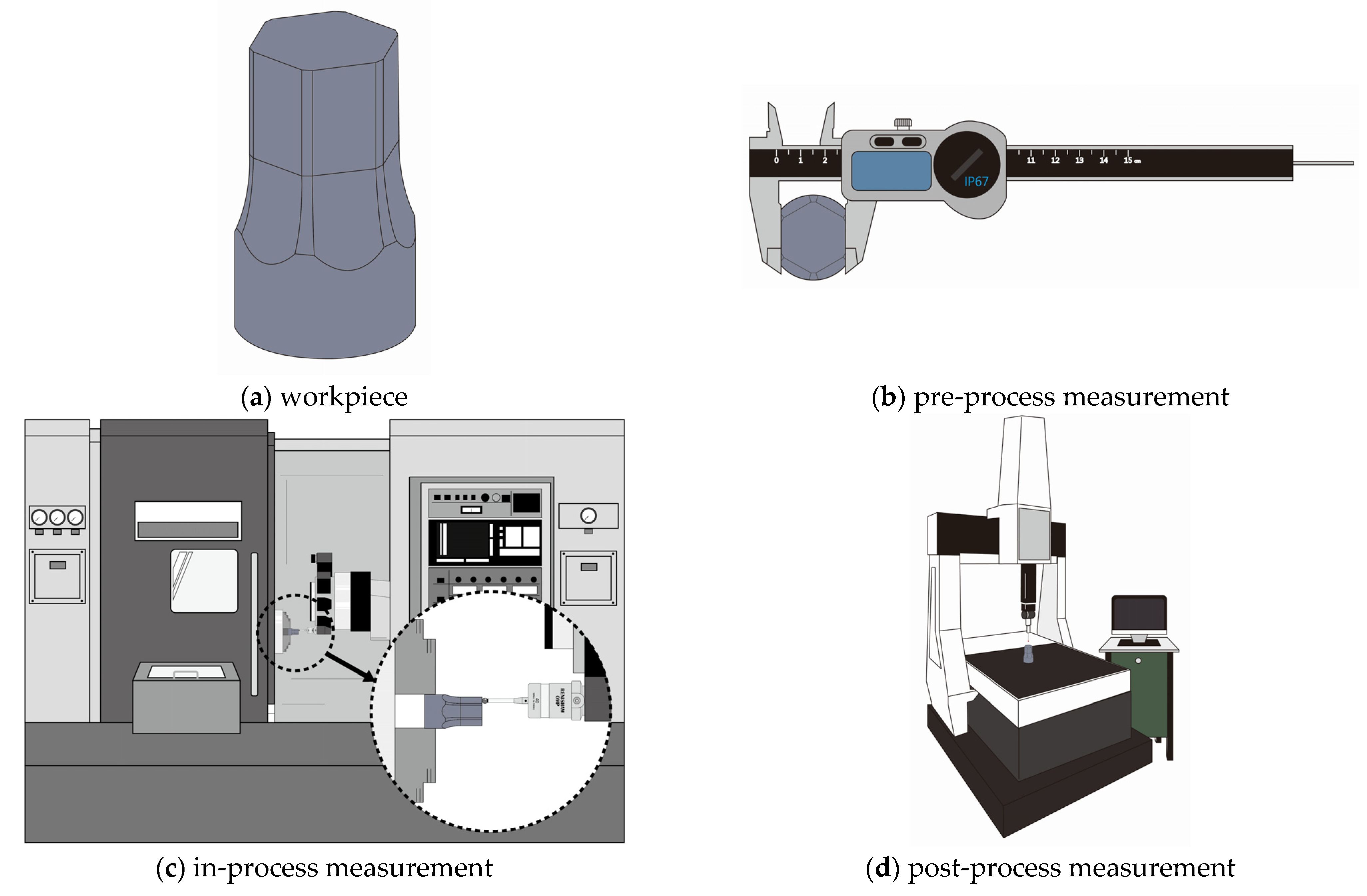
2. Workpiece Measurement Technology

The measurement technology can be divided into on-machine measurement, in situ measurement, and off-machine measurement; according to the measuring time and location, it can be divided into pre-process measurement, in-process measurement, and post-process measurement [21,22,23,24,25,26].

2.1. Pre-Process Measurement

Before machining, we can use measuring tools or fixtures to measure the workpiece, as shown in Figure 1b.

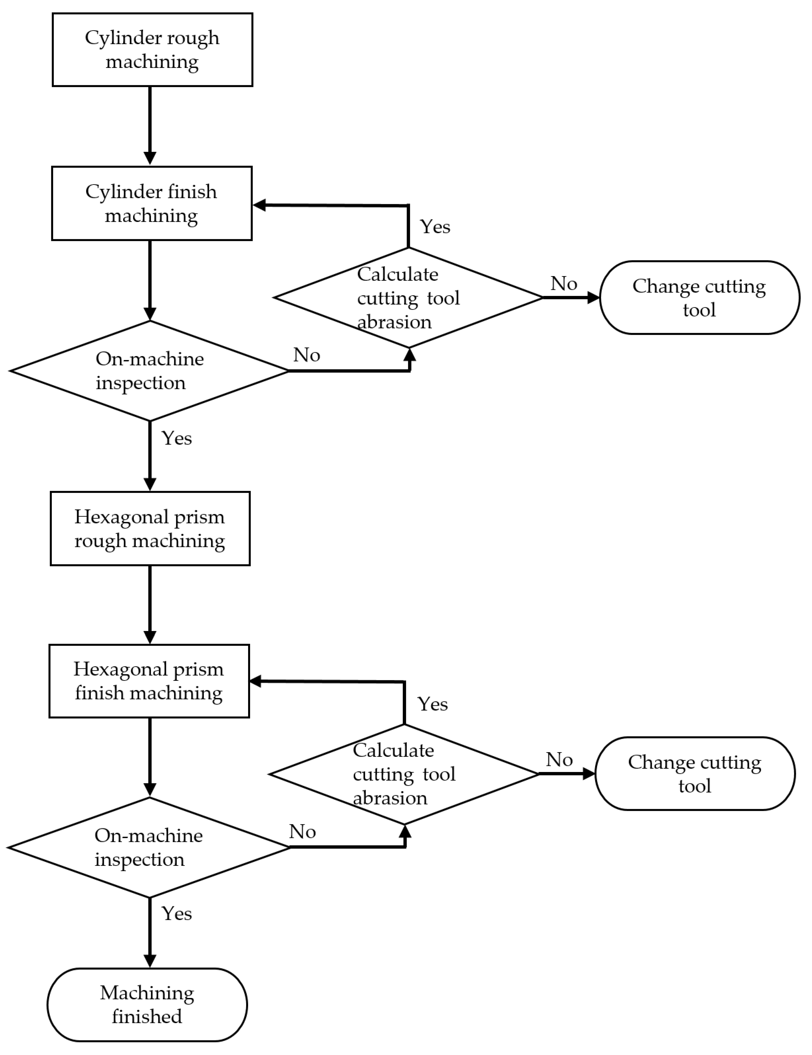
2.2. In-Process Measurement

As this step is usually performed on the machine tool, it will integrate with OMM, as shown in Figure 1c. One way to conduct in-process measurement is that in the actual machining process, we do not stop the machining process, but constantly obtain the size data in the machining process to detect whether the machining size is up to standard. The measurement method of in-process measurement is to use the cutting tool assembled with the touch sensor to process and can be equipped with a fast-cutting tool fixture to correct the tool, and also set tool coordinates to improve the accuracy of machining measurement. When the cutting tool positioning is completed before cutting, the cutting tool equipped with touch sensor will constantly feedback the machining point data for size comparison. The advantage of this measurement method is that it takes the cutting tool itself as the measurement probe, and there is no need to change the measurement tool before the measurement. Therefore, it can be processed and measured more quickly. But it is a big problem that there is also the interference of cutting chip and cutting fluid in use.
The other type is the in-cycle measurement, which uses the machining interval of each stage to replace the measuring tool for testing, and the measured data can be fed back to controller for compensation machining. The above steps can be performed repeatedly, and machining will be completed when the measured values meet the set values. The advantage of this method is that it can reduce the time spent on off-machine inspection and has high accuracy.

2.3. Post-Process Measurement

The finished workpiece is removed from the machine and moved to another testing machine such as 3D CMM for size inspection. Off-machine and moving to other inspection OMM after machining can avoid the error sources caused by the machine, such as vibration, cutting chip, and cutting fluid. However, it is also easy to say that the size is not up to the standard and needs to be processed again, as shown in Figure 1d.

3. Experimental Work

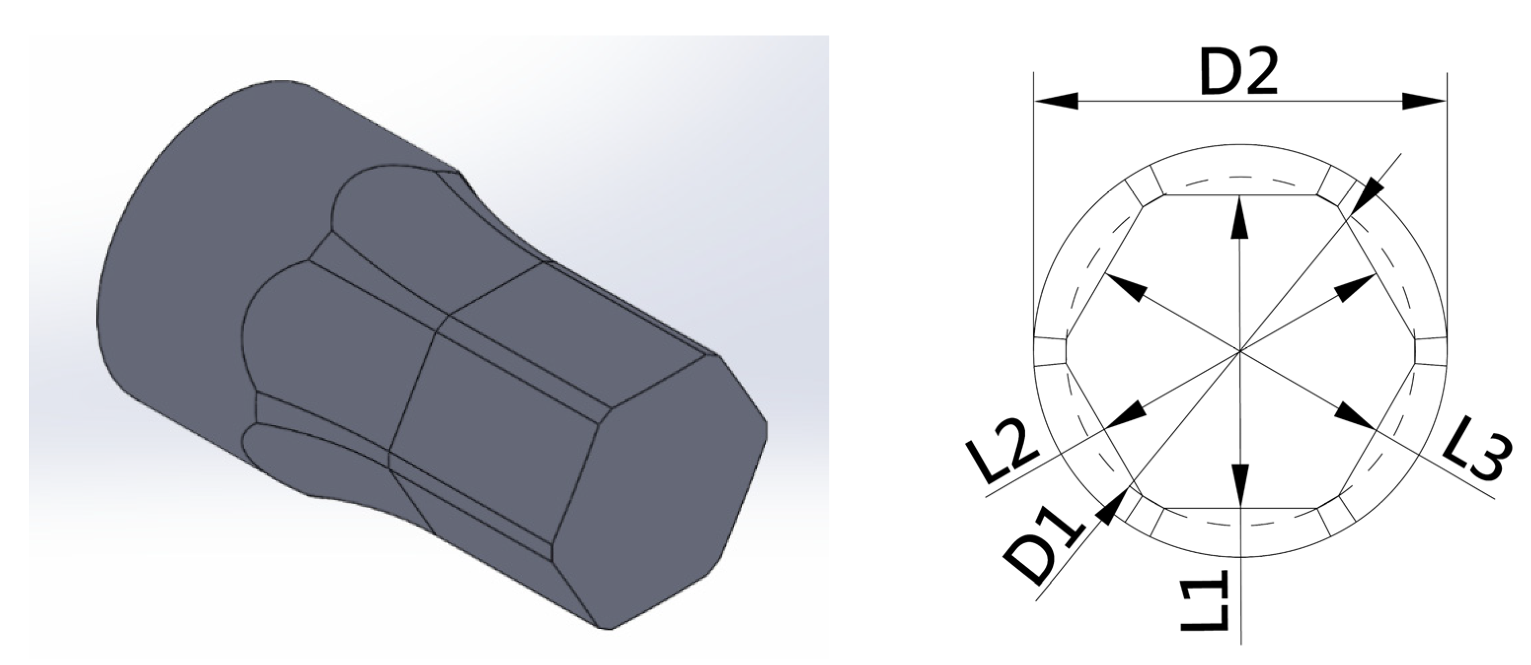
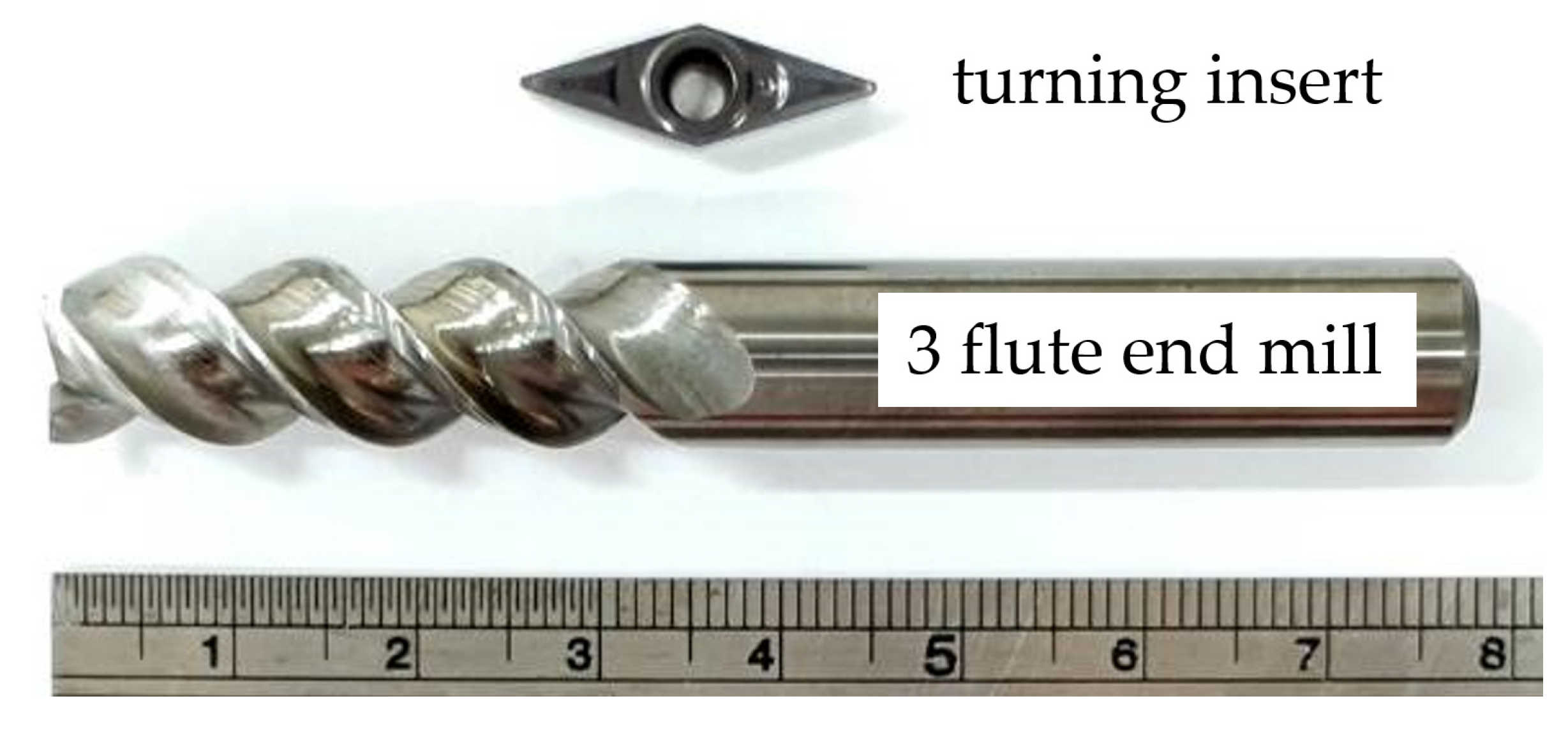
3.1. Workpiece and Cutting Tools

The workpiece material is A6061-T6 aluminum alloy bar material with Ø = 26 mm, which is a precipitation-hardening type of heat treatment alloy. The 6000 series of aluminum alloy with magnesium and silicon as the main alloy elements, thus, it is the most commonly used aluminum alloy. The geometric shape of the workpiece is a hexagonal punch. In the macro-programming machining path, the changed machining size can be set as shown in Figure 2. In the hexagonal punch, the sizes of the turning parts are D1 and D2, the sizes of the milling parts are L1, L2, and L3, and the sizes are set to D1 = 19.8 ± 0.01 mm and D2 = 23.5 ± 0.01 mm; L1, L2, and L3 are all 17.8 ± 0.01 mm. Figure 3 shows the used turning tools and end milling cutters. The turning part is a hard alloy aluminum turning tool (VCGT 130304-AK, Korloy, Seoul, Korea). The machining data of the rough turning were spindle speed 4700 rpm, depth-of-cut 0.5 mm and feed rate 0.3 mm/rev. The fine turning was same spindle speed and feed rate 0.15 mm/rev. The milling part is a 3-edge tungsten steel end milling cutter with Ø10 for aluminum alloy (AE51003TB, Speed Tiger, Taichung, Taiwan). The machining data of the milling were spindle speed 3000 rpm and feed rate 2000 mm/min.

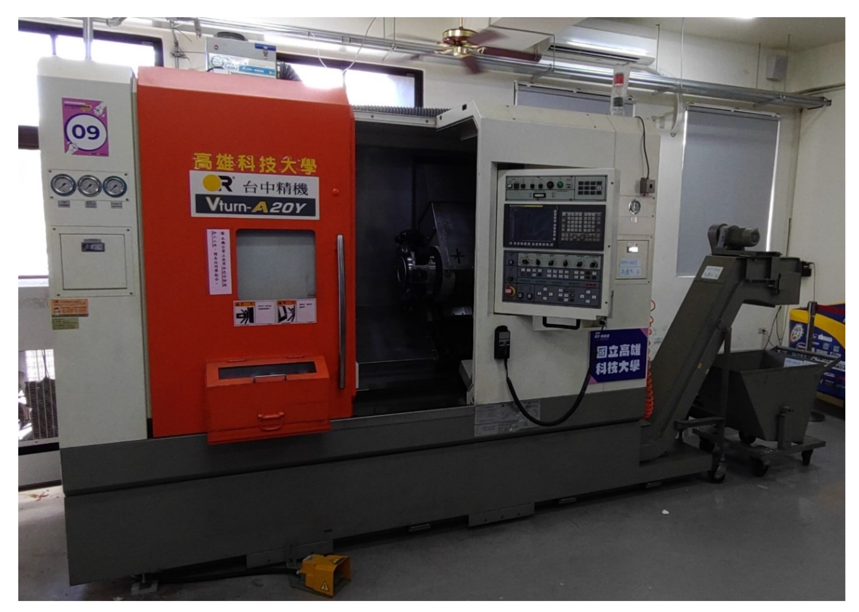
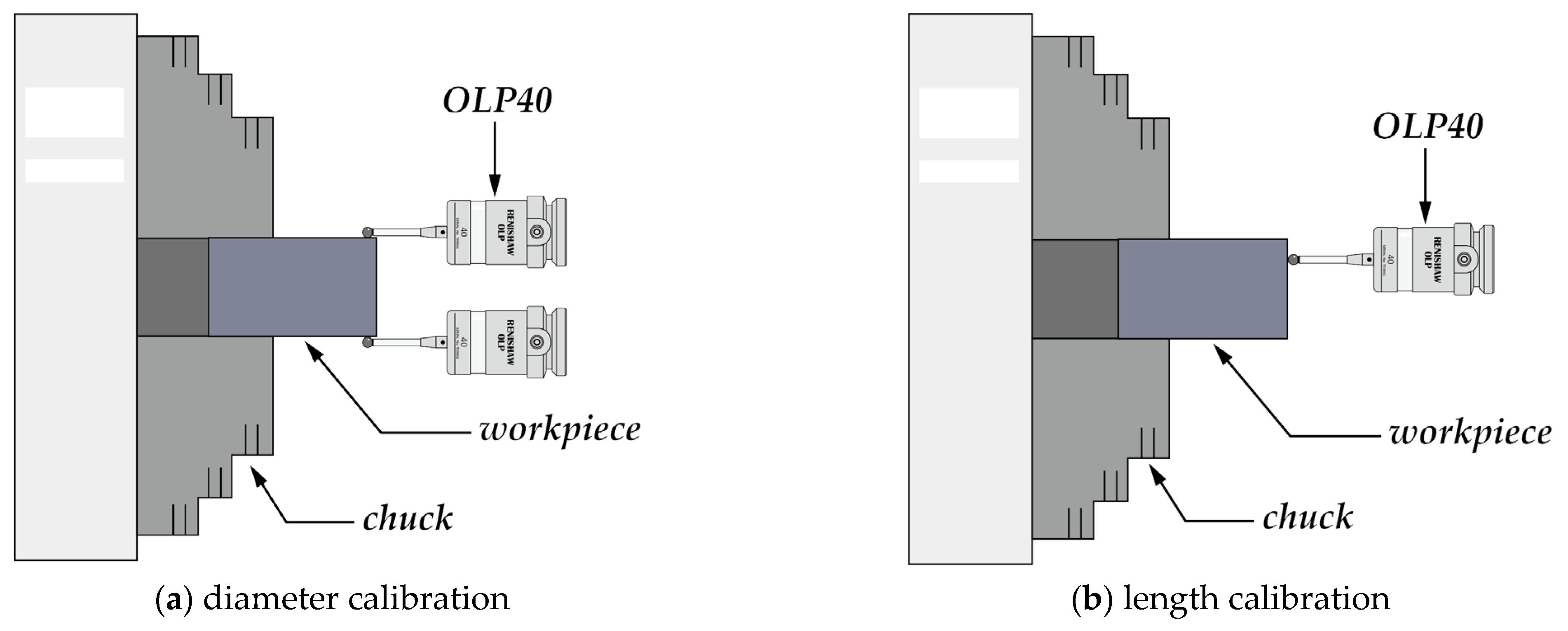
3.2. On-Machine Measuring System

The OMM system is established on the CNC turning-milling machine. The system is divided into cutting tool measuring device, workpiece measuring device, and Macro instructions. The CNC turning-milling machine model is Vturn-A20YCV, as shown in Figure 4. The controller adopts FANUC 0i-TF, and the maximum speed of the spindle can reach 5000 rpm. The maximum speed of fast movement of each axis can reach 24 mm/min. The fastest cutting feed is 1260 mm/min, the actual machining accuracy of the C axis of the spindle is ±0.01°, and the repeat positioning accuracy is ±0.010 mm.
The high precision motorized arm (HPMA) and tool setting probe (RP3) are adopted to correct the coordinate position of the cutting tool. When the cutting tool encounters the setting probe of RP3, the position coordinate will be returned to the controller and the cutting tool will be set as the reference tool. Other tools will be set sequentially using the reference tool with known size and coordinate position, and the accuracy can reach 1.0 μm.
We use the OLP40 contact probe (tough trigger probe). The probe is an electrical contact type and has the function of optical signal transmission with measurement accuracy of 1.0 μm. When any point of OLP40 contact probe touches the surface of the workpiece, the resistance in the probe will increase, and infrared light will be emitted on the side of the probe to transmit the signal from around. At this time, the contact signal is received through cooperating with OMI-2 optical machine interface (OMI). The received signal is transmitted through the transmission line to the CNC controller of the turning-milling machine, and the mechanical position at contact is calculated and recorded in the variables of the FANUC 0i-TF controller.
Since the program required for the contact lathe probe is a Marco program, the designs of both the machining path and measurement path are edited by Marco. The program flow of the hexagonal punch OMM is presented in Figure 5. The machining path and OMM program of hexagonal punch are written by Macro. The OMM is performed in machining, and then, the measured size data is compared with the standard size input in Macro. After comparison, there are three conditions to determine: Qualified size, over-cutting non-compensable size, and compensable size. If the compensable size is obtained after comparison, the program will determine whether the cutting tool abrasion is excessive. There will be remainders when there is too much abrasion loss. Table 1 is the main program O0399 of OMM and Macro-program O0404 of D1 size, # 700 is the design size of drawing, and # 600 is the size measured by contact probe. Subtraction of these two is the machining error size of # 716. When the size error is greater than 0.01 mm, it indicates that the machining is over-cut and machining will be stopped; if the size error is less than 0.01 mm, it indicates that it is within the tolerance range and the next machining pass is performed. # 10,002 is to record the cutting tool abrasion value. If this value is less than −0.11, it means too much cutting tool abrasion and will affect the machining size; the machining will be stopped. Table 2 lists the Macro programming of rough turning and finish turning of cylindrical machining, including O0400 and O0403 (P400 and P403 in Table 1).
First, the surface roughness of the hexagonal punch was measured with a Mitutoyo SJ-400 surface roughness tester to ensure that the size accuracy of the measurement would not have additional errors due to the surface roughness. Then, Cordax RS-25 coordinate measuring machine is used to check the size accuracy of the machined products. Results are compared with those of on-machine inspection by OLP40 contact probes. The instrument uses granite guide rails, which have low temperature variation and relatively stable accuracy and a repeatability accuracy of 3 μm.
When there are problems with the positioning accuracy of the machine, spindle, and probe calibration, they will affect the accuracy and repeatability of contact probe. Therefore, such problems are of great significance for probe calibration, such as the offset of X and Y direction of probe and the radius of probe ball nose, which will influence the accuracy of measurement. The lever-type dial indicator (scale = 0.002 mm) is taken as the measuring tool to correct the probe offset, and the subroutine of OLP40 contact probe function is used to correct the radius of the ball nose. Subroutines used are diameter calibration (P9082) and length calibration (P9801), as shown in Figure 6. The calibration procedure is as follows:
  • Use the diameter calibration (P9082) in OLP40 contact probe subroutine; build the X axis of the spindle to identify the axle center of the spindle;
  • Move the OLP40 contact probe to the center of the X axis of combined turning-milling machine;
  • Fix the dial indicator on the spindle claw and put the probe close to the probe ball nose, as shown in Figure 7;
  • Rotate the spindle to make the dial indicator probe rotate around the probe ball nose;
  • Adjust the X and Y directions so that the pointer of the lever-type dial indicator does not deviate;
  • After the above steps, the offsets of X and Y axes are compensated and corrected to the compensation value in the probe;
  • Then, adopt the diameter calibration (P9082) in the OLP40 contact probe subroutine, build the X axis of the spindle, and the radius compensation value of the ball nose is automatically found and stored in controller.
Using the above calibration procedure, the X axes of the probe and the spindle can be positioned so that they do not deviate. Then, the length calibration (P9801) in the OLP40 contact probe subroutine can be used to determine the position of the Z axis of the probe.

4. Results and Discussion

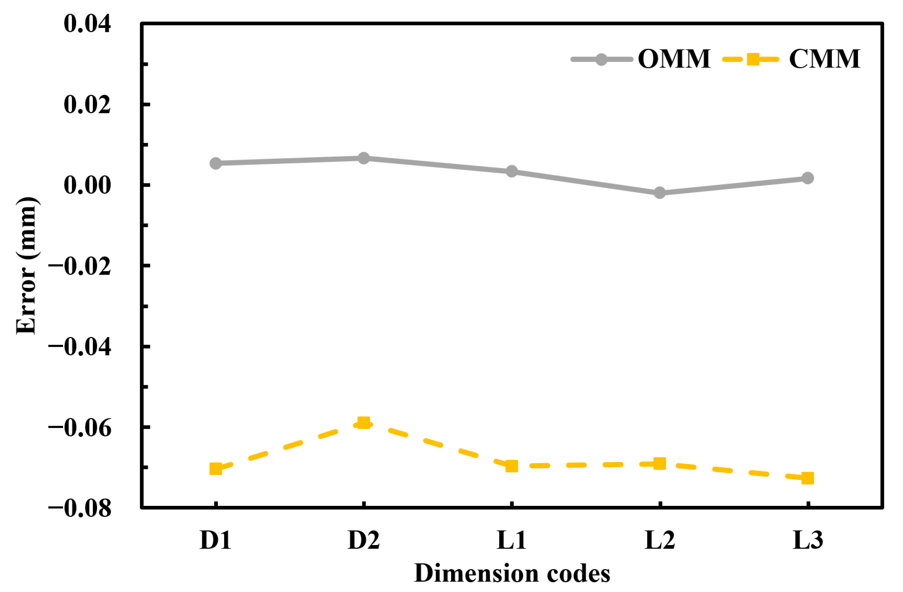
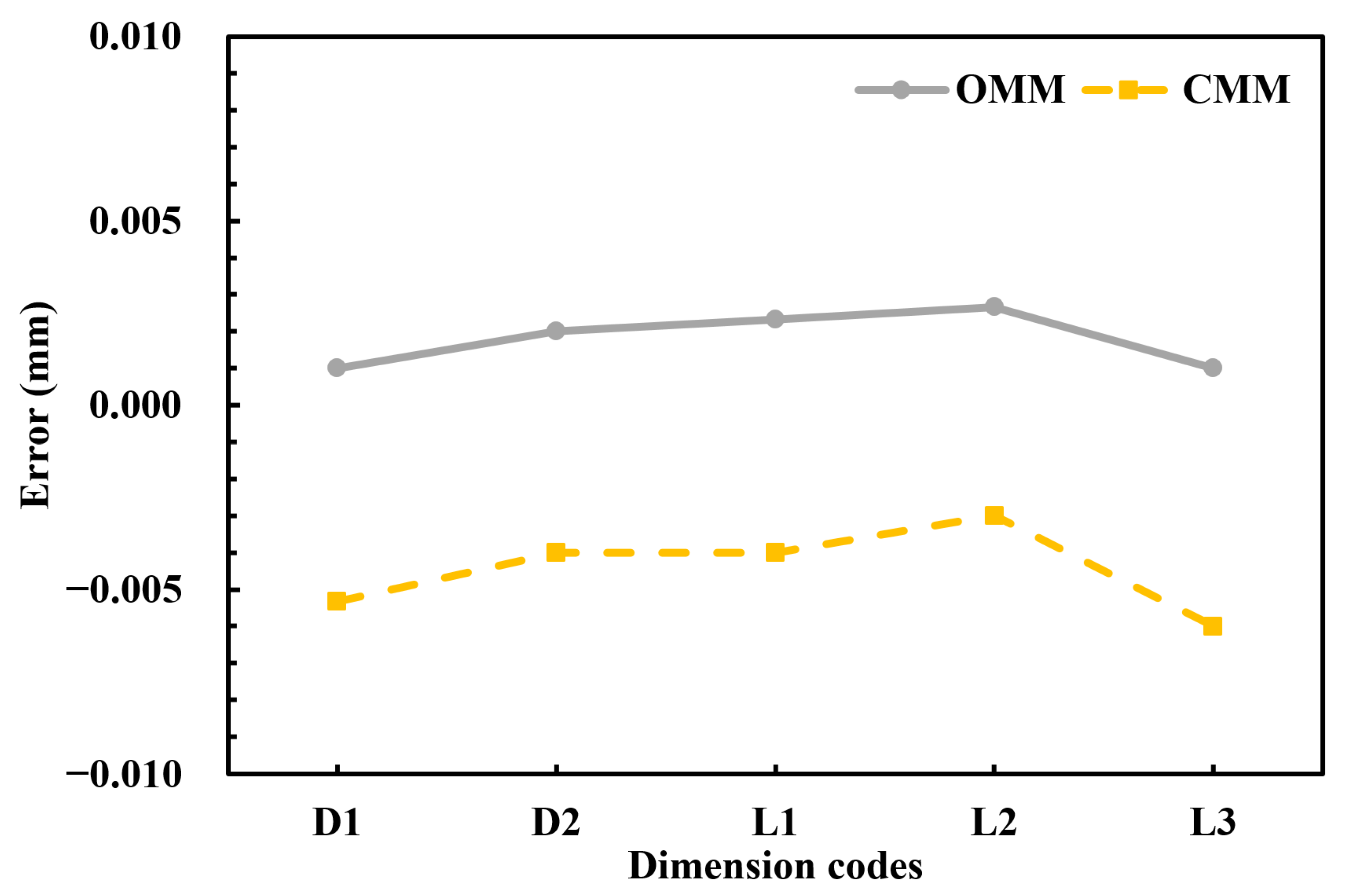
4.1. Size Errors before and after Calibration of on-Machine Measuring Systems

Before calibration of contact probe, OMM is performed on turning-milling machine after machining, the sizes D1, D2, L1, L2, and L3 of three hexagonal punches are measured. The error between the size data recorded in controller and the drawing size is compared. The finished hexagonal punches are moved to 3D CMM for off-machine measurement, and the errors are compared between the sizes obtained after inspection and the size data on the original CAD diagram. Table 3 and Figure 8 show the results by OMM (before probe calibration) and CMM. As observed, the surface roughness after turning is 0.23–0.25 μm, and the surface roughness after milling is 0.434–0.486 μm. Both reach the surface quality of finish machining, thus, not affecting the size error. The measurement results by OMM, the average value and the error value of D1 were 19.805 mm and 0.005 mm; the average value and the error value of D2 were 23.506 mm and 0.007 mm; the average value and the error value of L1 were 17.803 mm and 0.003 mm; the average value and the error value of L2 were 17.798 mm and −0.002 mm; the average value and the error value of L3 were 17.802 mm and 0.002 mm. The measurement results by CMM, the average value and the error value of D1 were 19.730 mm and −0.07 mm; the average value and the error value of D2 were 23.441 mm and −0.059 mm; the average value and the error value of L1 were 17.730 mm and −0.07 mm; the average value and the error value of L2 were 17.731 mm and −0.069 mm; the average value and the error value of L3 were 17.727 mm and −0.073 mm. As shown in Figure 8, the error between the result of OMM and the drawing size is within the tolerance (±0.01 mm), and the maximum error is 0.006 mm. However, the size error of the results measured by CMM is more than 0.05 mm, which has exceeded the tolerance range of the drawing size (±0.01 mm); therefore, there is the phenomenon of over-cutting.
Table 4 and Figure 9 show the results by OMM (after calibration of contact probe) and 3D measuring bed. The measurement results by OMM, the average value and the error value of D1 were 19.801 mm and 0.001 mm; the average value and the error value of D2 were 23.502 mm and 0.002 mm; the average value and the error value of L1 were 17.802 mm and 0.002 mm; the average value and the error value of L2 were 17.803 mm and 0.003 mm; the average value and the error value of L3 were 17.801 mm and 0.001 mm. The measurement results by CMM, the average value and the error value of D1 were 19.795 mm and −0.005 mm; the average value and the error value of D2 were 23.496 mm and −0.004 mm; the average value and the error value of L1 were 17.796 mm and −0.004 mm; the average value and the error value of L2 were 17.797 mm and −0.003 mm; the average value and the error value of L3 were 17.794 mm and −0.006 mm. As observed, the size errors of the hexagonal punch after probe calibration obtained in 3D CMM and OMM are all within the tolerance range (±0.01 mm).
Since the positioning accuracy of the machine and spindle, probe calibration, and the surface quality after machining will be reflected in the accuracy of contact probe measurement in actual machining [22,25,27,28,29], it will lead to the results shown in Table 3 and Figure 8. After probe calibration, which is presented in Section 3.2, it can meet the required tolerance range, i.e., ±0.01 mm, indicating that the method of machining measurement and compensation machining of OMM during the machining is feasible, as shown in Table 4 and Figure 9.

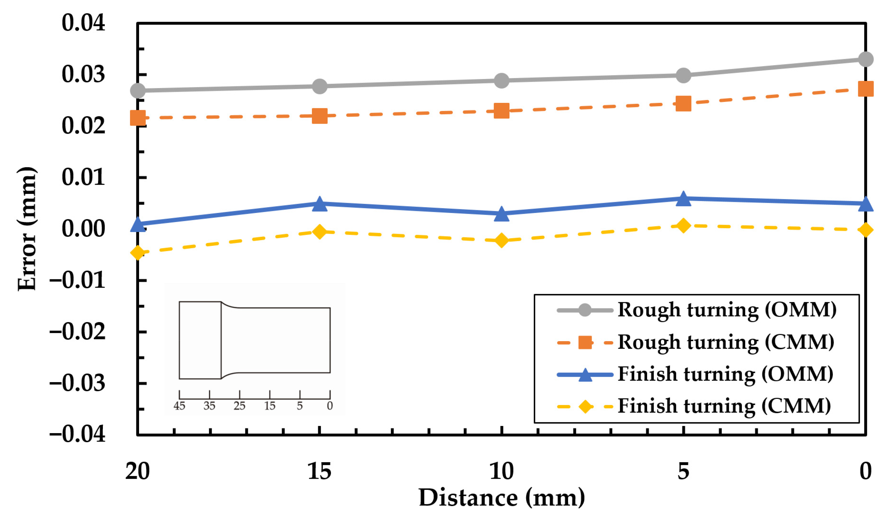
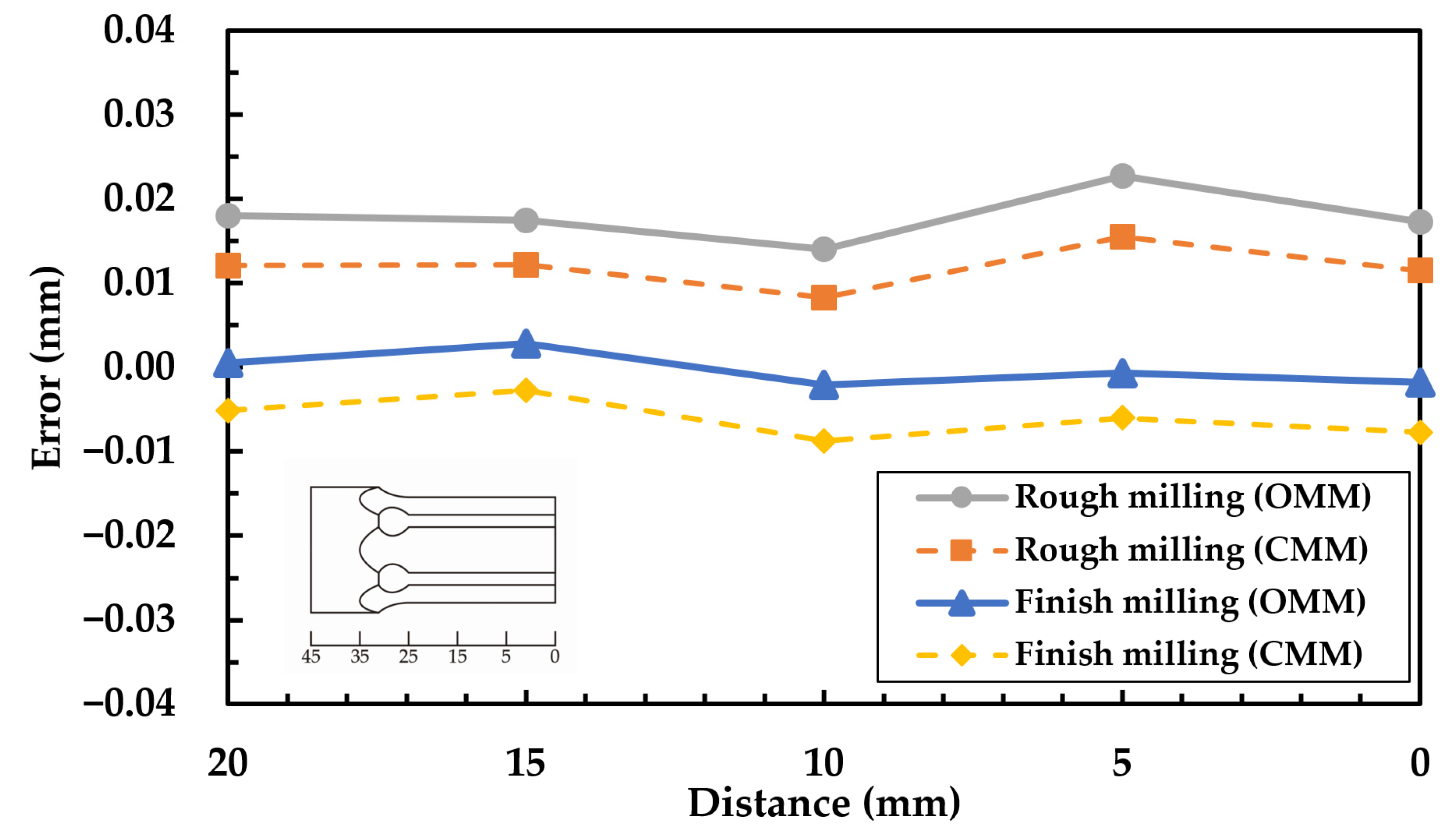
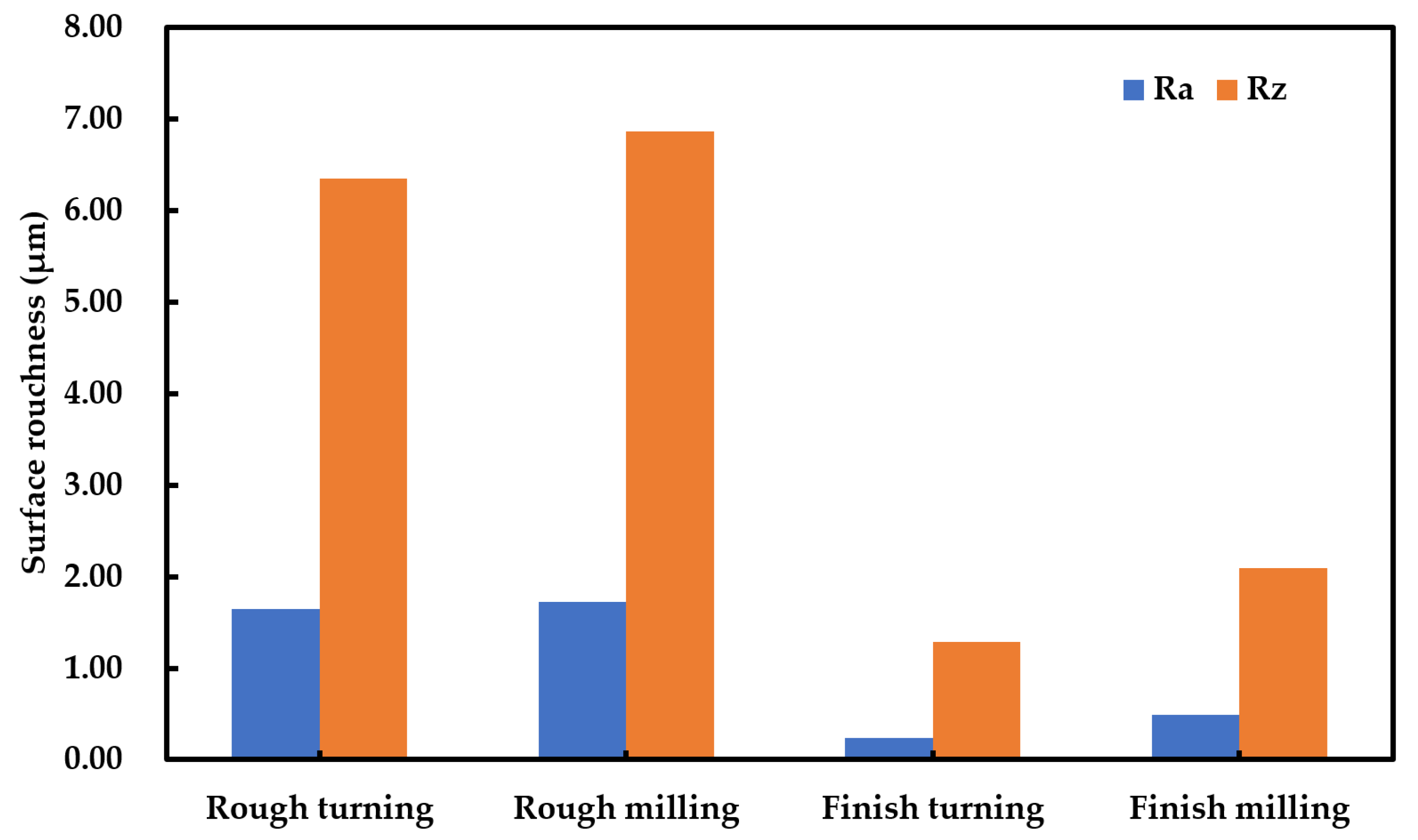
4.2. Effects of Turning and Milling on on-Machine Measuring

The machining program is divided into rough machining and finish machining for turning and milling. After rough machining, OMM is performed, and then, finish machining is performed after inspection. OMM is performed again after finish machining, and the size errors are shown in Figure 10 and Figure 11. According to the measured size errors after turning, the size error of rough machining is larger than that of finish machining. The error at the end of the workpiece reaches a maximum of ~0.035 mm and needs to be compensated several times before its size is within the set tolerance range. As the purpose of rough machining is to remove excess materials quickly and cut with large feed and cutting depth, the size error is larger when the workpiece is further away from the clamping end [24,29]. After finish machining, it can be found that the errors can be kept within the set tolerance range. According to the size errors measured after milling, the size error of rough machining is also larger than that of finish machining. Due to the fixed C axis in milling, the size error of the clamping end of the workpiece is consistent with the two size errors of the workpiece ends. After finish machining, it can be found that the errors can be kept within the set tolerance range. The Figure 12 show the measurement of surface roughness parameters including Ra and Rz, after rough and finish machining respectively. As observed, the surface roughness after rough turning were about Ra = 1.645 μm and Rz = 6.352 μm; the surface roughness after rough milling were about Ra = 1.727 μm and Rz = 6.858 μm; the surface roughness after finish turning were about Ra = 0.236 μm and Rz = 1.283 μm; the surface roughness after finish milling were about Ra = 0.488 μm and Rz = 2.095 μm. Figure 13 is the surface shapes after rough milling and finish milling. As observed, the surface quality and size accuracy of rough machining are worse than those of finish machining due to the vibration in rough machining [30].

5. Conclusions

Using OLP40 contact probe and Macro programming, the OMM of combined turning-milling machine and compensation machining system are designed. Taking full advantage of the high repeatability and high precision of OLP40 contact probe, the size is measured successfully in machining. The size error is effectively compensated to the set tolerance range. Using this method, path planning, manufacturing, and measurement can be integrated into a single processing machine, and the time of off-machine measurement and repositioning for secondary machining can be saved, thereby significantly improving the production efficiency and product yield and avoiding unnecessary errors. The contact probe needs to be corrected before machining. If there is no center calibration between the machine spindle and the probe, the measurement size will be inaccurate. In this case, accurate compensation machining cannot be realized, resulting in over-cutting of the workpiece. The size error of rough machining is larger than that of finish machining, and the size error of rough machining will increase with the length of the workpiece.
In the future, two or more measurement functions can be used to match the measurement, and the use of mathematical expressions to calculate the more complex dimensions, such as 3D complex surfaces.

Author Contributions

Conceptualization, C.-H.K.; methodology, C.-H.K.; software, P.-C.C.; validation, P.-C.C.; investigation, C.-H.K.; resources, C.-H.K.; writing—original draft preparation, C.-H.K.; writing—review and editing, C.-H.K.; supervision, C.-H.K. Both authors have read and agreed to the published version of the manuscript.

Funding

This research received no external funding.

Institutional Review Board Statement

Not applicable.

Informed Consent Statement

Not applicable.

Data Availability Statement

Data is contained within the article.

Conflicts of Interest

The authors declare no conflict of interest.

References

  1. Zeleny:, J.; Janda, M. Automatic on-machine measurement of complex parts. MM Sci. J. 2009, 2, 92–95. [Google Scholar] [CrossRef]
  2. Liu, H.B.; Wang, Y.Q.; Jia, Z.Y.; Guo, D.M. Integration strategy of on-machine measurement (OMM) and numerical control (NC) machining for the large thin-walled parts with surface correlative constraint. J. Adv. Manuf. Technol. 2015, 80, 1721–1731. [Google Scholar] [CrossRef]
  3. Wang, G.; Li, W.L.; Rao, F.; He, Z.R.; Yin, Z.P. Multi-parameter optimization of machining impeller surface based on the on-machine measuring technique. Chin. J. Aeronaut. 2019, 32, 2000–2008. [Google Scholar] [CrossRef]
  4. Chen, Y.T.; More, P.; Liu, C.S. Identification and verification of location errors of rotary axes on five-axis machine tools by using a touch-trigger probe and a sphere. J. Adv. Manuf. Technol. 2019, 100, 2653–2667. [Google Scholar] [CrossRef]
  5. Li, Y.D.; Gu, P.H. Free-form surface inspection techniques state of the art review. Comput. Aided Des. 2004, 36, 1395–1417. [Google Scholar] [CrossRef]
  6. Del Guerra, M.; Coelho, R.T. Development of a low cost Touch Trigger Probe for CNC Lathes. J. Mater. Process. Technol. 2006, 179, 117–123. [Google Scholar] [CrossRef]
  7. Kaťuch, P.; Dovica, M.; Slosarč’k, S.; Kováč, J. Comparision of contact and contactless measuring methods for form evaluation. Procedia Eng. 2012, 48, 273–279. [Google Scholar] [CrossRef] [Green Version]
  8. Stojkic, Z.; Culjak, E.; Saravanja, L. 3D measurement-comparison of CMM and 3D scanner. In Proceedings of the 31st DAAAM International Symposium, Vienna, Austria, 21–24 October 2020. [Google Scholar] [CrossRef]
  9. Waiyagan, K.; Bohez, E.L.J. Intelligent feature based process planning for five-axis mill-turn parts. Comput. Ind. 2009, 60, 296–316. [Google Scholar] [CrossRef]
  10. Zhu, L.; Jiang, Z.H.; Shi, J.S.; Jin, C.Z. An overview of turn-milling technology. Int. J. Adv. Manuf. Technol. 2015, 81, 493–505. [Google Scholar] [CrossRef]
  11. Zhao, Z.C.; Xu, T.R. A novel approach for process shape construction in adaptive machining of curved thin-walled part. Precis. Eng. 2021, 67, 282–292. [Google Scholar] [CrossRef]
  12. Zhang, Y.; Chen, Z.; Zhu, Z. Adaptive machining framework for the leading/trailing edge of near-net-shape integrated impeller. Int. J. Adv. Manuf. Technol. 2020, 107, 4221–4229. [Google Scholar] [CrossRef]
  13. Ge, G.Y.; Du, Z.C.; Feng, X.B.; Yang, J.G. An integrated error compensation method based on on-machine measurement for thin web parts machining. Precis. Eng. 2020, 63, 206–213. [Google Scholar] [CrossRef]
  14. Ma, W.K.; He, G.Y.; Han, J.X.; Xie, Q.C. Error compensation for machining of sculptured surface based on on-machine measurement and model reconstruction. Int. J. Adv. Manuf. Technol. 2020, 106, 3177–3187. [Google Scholar] [CrossRef]
  15. Du, Z.C.; Ge, G.Y.; Xiao, Y.K.; Feng, X.B. Modeling and compensation of comprehensive errors for thin-walled parts machining based on on-machine measurement. Int. J. Adv. Manuf. Technol. 2021, 115, 3645–3656. [Google Scholar] [CrossRef]
  16. Özel, C.; Inan, A.; Özler, L. An investigation on manufacturing of the straight bevel gear using end mill by CNC milling machine. J. Manuf. Sci. Eng. 2005, 127, 503–511. [Google Scholar] [CrossRef]
  17. Özel, C. Research of production times and cutting of the spur gears by end mill in CNC milling machine. Int. J. Adv. Manuf. Technol. 2011, 54, 203–213. [Google Scholar] [CrossRef]
  18. Joshi, V.K.; Desai, K.P.; Raval, H.K. CNC milling of planar curves using macro programming. J. Manuf. Eng. 2016, 11, 013–019. [Google Scholar]
  19. Hasan, M.A. A conceptual framework of common variables in CNC machines programming for Fanuc custom macros. J. Mat. Sci. Mech. Eng. 2016, 3, 250–253. [Google Scholar]
  20. Nguyen, T.K.; Phung, L.X.; Bui, N.T. Novel integration of CAPP in a G-code generation module using macro programming for CNC application. Machines 2020, 8, 61. [Google Scholar] [CrossRef]
  21. Shiraishi, M. Scope of in-process measurement, monitoring and control techniques in machining processes—Part 1: In-process techniques for tools. Precis. Eng. 1988, 10, 179–189. [Google Scholar] [CrossRef]
  22. Shiraishi, M. Scope of in-process measurement, monitoring and control techniques in machining processes—Part 2: In-process techniques for workpieces. Precis. Eng. 1989, 11, 27–37. [Google Scholar] [CrossRef]
  23. Shiraishi, M. Scope of in-process measurement, monitoring and control techniques in machining processes—Part 3: In-process techniques for cutting processes and machine tools. Precis. Eng. 1989, 11, 39–47. [Google Scholar] [CrossRef]
  24. Liu, Z.Q.; Venuvinod, P.K.; Ostafiev, V.A. On-machine measurement of workpieces with the cutting tool. Integr. Manuf. Syst. 1998, 9, 168–172. [Google Scholar] [CrossRef]
  25. Takaya, Y. In-process and on-machine measurement of machining accuracy for process and product quality management: A review. Int. J. Autom. Technol. 2014, 8, 4–19. [Google Scholar] [CrossRef]
  26. Horst, J.; Hedberg, T.; Feeney, A.B. On-machine measurement use cases and information for machining operations. Natl. Inst. Stand. Technol. Adv. Man. Ser. 2019, 400–401, 1–69. [Google Scholar] [CrossRef]
  27. Kim, S.H.; Lee, S.W.; Kim, D.H.; Lee, A.S.; Lim, S.J.; Park, K.T. Geometric accuracy measurement of machined surface using the OMM (on the machine measurement) system. Int. J. Precis. Eng. Manuf. 2003, 4, 57–63. [Google Scholar]
  28. Ibaraki, S.; Iritani, T.; Matsushita, T. Calibration of location errors of rotary axes on five-axis machine tools by on-the-machine measurement using a touch-trigger probe. Int. J. Mach. Tools Manuf. 2012, 58, 44–53. [Google Scholar] [CrossRef] [Green Version]
  29. Liu, Z.Q. Repetitive measurement and compensation to improve workpiece machining accuracy. Int. J. Adv. Manuf. Technol. 1999, 15, 85–89. [Google Scholar] [CrossRef]
  30. Altintas, Y. Manufacturing Automation: Metal Cutting Mechanics, Machine Tool Vibrations, and CNC Design, 2nd ed.; Cambridge University Press: Cambridge, UK, 2012. [Google Scholar]
Figure 1. Schematic diagram of workpiece measurement technology (a) workpiece; (b) pre-process measurement; (c) in-process measurement; (d) post-process measurement.
Machines 09 00180 g001
Figure 2. CAD drawings (left) and specifications (right) of hexagonal punches.
Machines 09 00180 g002
Figure 3. Cutting tools of turning and milling.
Machines 09 00180 g003
Figure 4. Vturn-A20YCV CNC turning-milling machine.
Machines 09 00180 g004
Figure 5. Flow chart of the procedure of inspection on the hexagonal punching machine.
Machines 09 00180 g005
Figure 6. (a) Diameter and (b) length calibration schematic diagram.
Machines 09 00180 g006
Figure 7. Calibration of the probe offset with a lever-type dial indicator.
Machines 09 00180 g007
Figure 8. Comparison chart of measurement between OMM (before probe calibration) and CMM.
Machines 09 00180 g008
Figure 9. Comparison chart of measurement between OMM (after probe calibration) and CMM.
Machines 09 00180 g009
Figure 10. Machining errors along the length of the workpiece in turning machining.
Machines 09 00180 g010
Figure 11. Machining errors along the length of the workpiece in milling machining.
Machines 09 00180 g011
Figure 12. Surface roughness of the workpiece in rough and finish machining.
Machines 09 00180 g012
Figure 13. Shape of surface after (a) rough milling; and (b) finish milling.
Machines 09 00180 g013
Table 1. Macro programming for on-machine inspection of D1 size.
Process of OMMD1 Measurement
Machines 09 00180 i001 Machines 09 00180 i002
Table 2. Macro programming for cylinder rough turning and finish turning.
Rough TurningFinish Turning
%%
O0400; O0403;
G28 U0. W0.;#718=#700+#10002;
M46;G28 U0. W0.;
G0 T0101;M46;
¦G0 T0202;
G0 X[#701+1];¦
G71 U0.5 R1.;G0 G40 X40. Z3.;
G71 P101 Q102 U0.2 W0.1 F0.15;G01 G42 X5.715 F0.15;
N101 G01 X-5.715;Z-0.5;
Z-0.5;G01 X#718;
G01 X#700;Z-#702;
Z-#702;G02 U[#704*2] Z-[#702+#705] R10.;
G02 U[#704*2] Z-[#702+#705] R10.;G01 W-10.;
G01 W-10.;U3.;
N102 U3.;G0 X40. Z3.;
G0 X40. Z3.;M99;
M99;%
%
Table 3. Comparison table of measurement between OMM (before probe calibration) and CMM.
On-Machine MeasuringCoordinate Measuring Machine
D1D2L1L2L3D1D2L1L2L3
CAD (mm)19.823.517.817.817.819.823.517.817.817.8
N1 (mm)19.80623.50617.80417.80117.80819.72823.43417.73317.74517.734
N2 (mm)19.80223.50417.80017.79217.79919.73323.45717.73617.73417.735
N3 (mm)19.80823.51017.80617.80117.79819.72823.43217.72217.71417.713
Avg.19.80523.50617.80317.79817.80219.73023.44117.73017.73117.727
Error0.0050.0070.003−0.0020.002−0.070−0.059−0.070−0.069−0.073
Ra (μm)0.250.230.4860.4560.4340.250.230.4860.4560.434
Table 4. Comparison table of measurement between OMM (after probe calibration) and CMM.
On-Machine MeasuringCoordinate Measuring Machine
D1D2L1L2L3D1D2L1L2L3
CAD (mm)19.823.517.817.817.819.823.517.817.817.8
N1 (mm)19.80023.50117.80117.80117.79919.79623.49317.79417.79417.792
N2 (mm)19.80223.50317.80317.80417.80319.79623.49917.79817.80017.796
N3 (mm)19.80123.50217.80317.80317.80119.79223.49617.79617.79717.794
Avg.19.80123.50217.80217.80317.80119.79523.49617.79617.79717.794
Error0.0010.0020.0020.0030.001−0.005−0.004−0.004−0.003−0.006
Ra (μm)0.240.230.4830.4520.4350.240.230.4830.4520.435
Publisher’s Note: MDPI stays neutral with regard to jurisdictional claims in published maps and institutional affiliations.

