1. Introduction
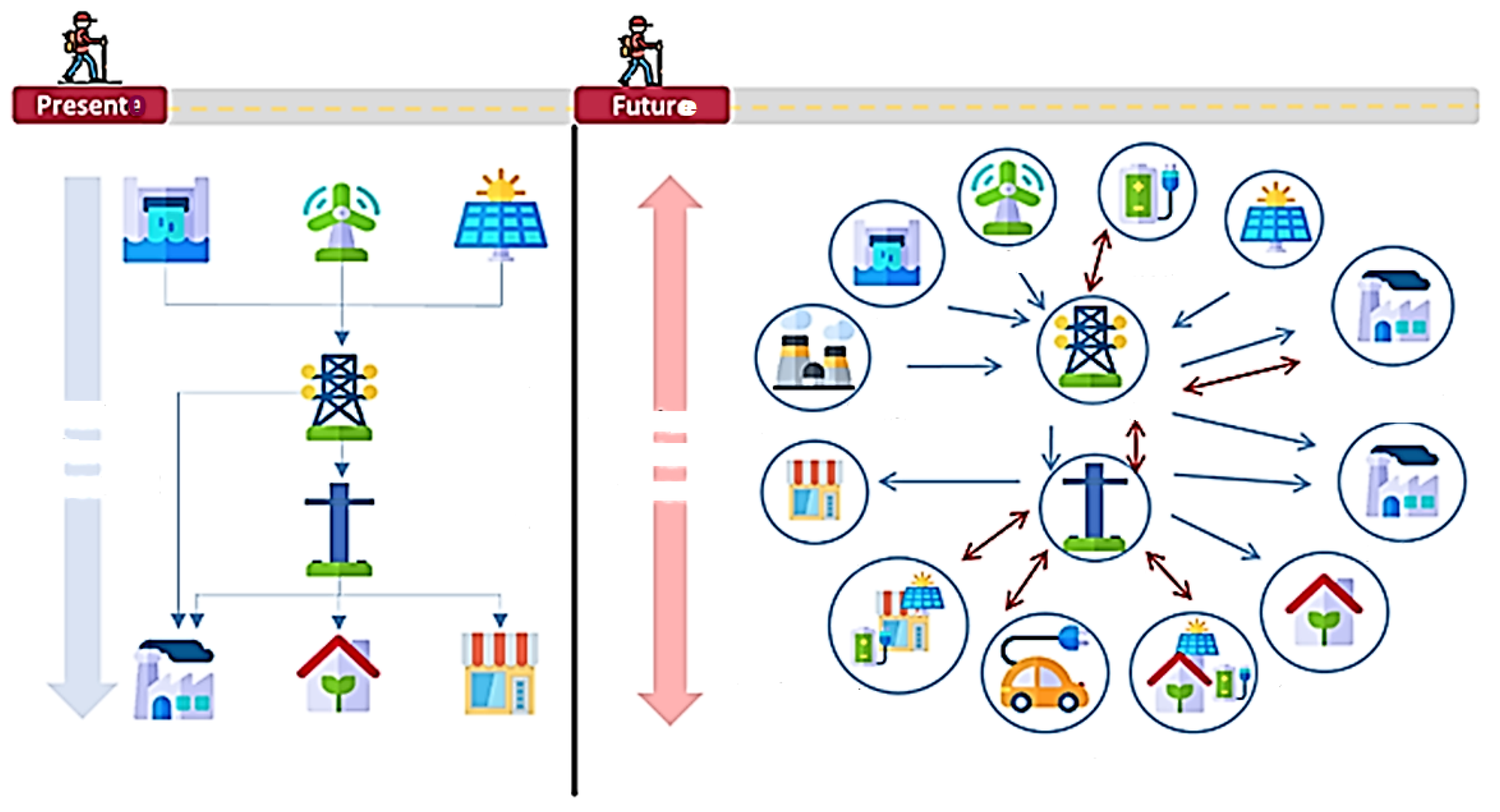
Sustainable smart grid (SG) systems are a viable alternative to face the demand of improving and diversifying energy supply services, relying on distributed systems that are also adaptable to specific consumers.
The design challenge is to integrate legacy energy supply; to fit all requirements emanated from hybrid consumers who are now producers (or prosumers); and to simultaneously maintain energy quality. The resulting system is open since it is possible to introduce or remove new prosumers. New design approaches are a demand to face this challenge [
1].
Traditional distribution energy supply relies on a general method related to matching theory (even if the designers explicitly use this association) [
2]. A “well-posted” problem
P related to energy supply should match known systems and equipment or previously studied and practiced methods. Typically, the demand is to organize and optimize distribution from a centralized energy provider and user demands are not personalized. Users are classified into generic classes.
Automation is a control or optimized control problem for traditional energy systems, admitting a small degree of “intelligence”. For distributed production-consuming flexible energy services, as described above, design automation is a collaborative multiagent system, which could also be intelligent–coupling with the consumer results from personal requirements and no longer from generic classification. Design methods should face all these demands.
In a single word, we must say that the demand is now for a distributed prosumer service system, where the term “service” carries the usual meaning provided by the Service Science [
3].
Figure 1 illustrates this change [
4].
We claim that new design methods for energy service distribution must be interdisciplinary, integrating traditional methods and practices, and others typically used in ICT (Information and Communication Technology) or in multiagent systems. Since we are now dealing with services, instead of direct provision, another demand is to introduce Service Engineering Design (SED).
The initial requirements phase acquires importance once it should model the integration of distributed agents in a service ecosystem merged by a central energy provider. The coupling with the consumer (who is also a provider) must be included in this model, which was never done by traditional methods [
6].
Requirements validation is not straightforward for the described ecosystem. Actually, for automated systems, formal representation and verification are key issues, leading to a cycle composed of modeling, formalization, and verification. Existing methods consider this cycle a preliminary stage, where the problem
P is modeled after some refinements, leading to a model-based requirements approach [
7,
8,
9].
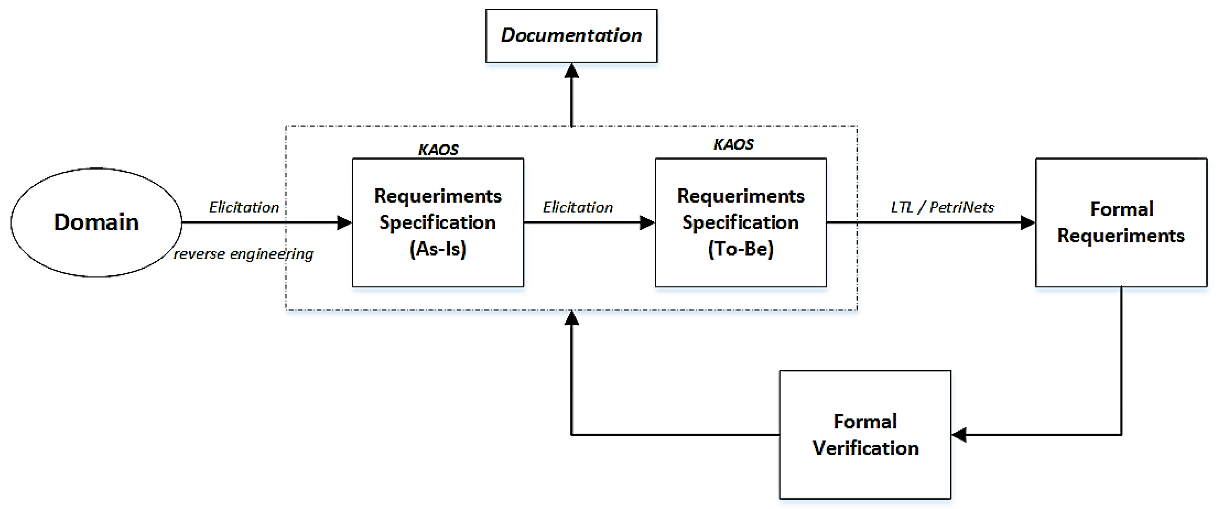
This article presents a proposal for the formal requirements modeling cycle, relying on a goal-oriented approach customarily used for automated systems including hardware and software, as in metro systems. We anticipate formalization to the requirements phase using a preliminary representation in a schematic language called KAOS (Knowledge Acquisition and Object Specification) [
10], fitting into model-based requirements engineering (MBRE) [
11]. Therefore, requirements are captured in a diagramatic model (KAOS), starting with a preliminary requirement specification and a refinement cycle composed of analysis and formalization in a formal language (Petri Nets); followed by a property analysis and (formal) verification; and a post-modeling analysis, which points to further improvements. The cycle iterates up to a final model that feeds the design of solutions, formalized in the same language (Petri Nets). In the design phase, developers should look for matching between the problems specified and the available (or new) solutions to produce energy to store [
12] or insert other sustainable alternatives as wind turbines [
13].
This article is organized as follows:
Section 2 presents the background and state of the art.
Section 3 provides a conceptual description of the proposed method.
Section 4 presents its application in a case study and the results. Finally, a concluding section overviews the contributions of this work and suggests perspectives on future work.
This article is an extended version of the paper presented in the 14th International Conference of
, INDUSCON2021, in Portuguese [
5].
2. Design Perspectives to Energy Systems
Smart grid (SG) ecosystem design brings new demands that insert this process in the category of complex energy systems due to its connections with different areas of knowledge (e.g., physics, engineering, communication, and even human–systems interaction) [
14].
However, from a systems engineering perspective, the most significant change from traditional methods is treating generation and distribution environments as systems rather than arrays of products or devices [
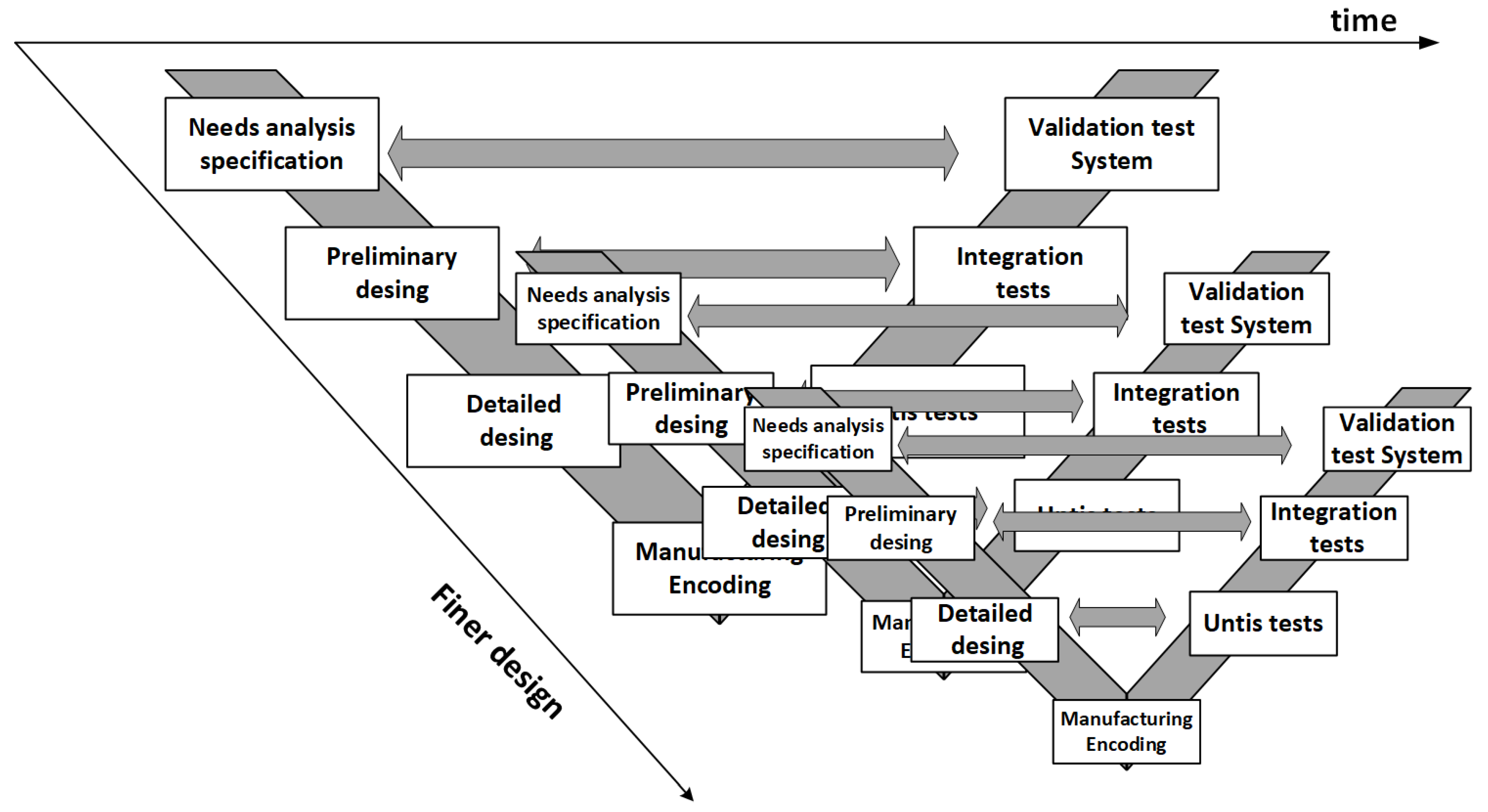
15]. Attempts to modify and modernize the conventional design approach by considering the introduction of ICT or even software methods such as the “V” model, also used by the manufacturing industry, have been employed. The “V” model derived from the structured approach for software was adapted to model systems, including software, hardware, and interactions with users. Essentially, the “V” is a “top-down” method, where one part of the “V” goes down from the requirements to prototyping and goes through both system analysis and design. The other part of the “V” goes up from prototyping to system delivering, going through local tests, integration tests, and final deployment. In attempting to adapt this method to the design of electrical energy systems, Roboam [
15] proposed an extended model, including some recursion and interlaced multiples Vs.
Figure 2 depicts the essence of this hierarchical view.
Roboam [
15] was already concerned with presenting a systemic proposal, even if it still followed the basic steps functionally, as in the classic “V”. The novelty relies on the proposition of an extended life cycle, starting with a requirements phase, which is not particularly present in the conventional design of energy systems. The drawback is the difficulty of adapting this proposal for distributed systems. An alternative was to use an iteration of “V” cycles to recover flexibility. Requirements were represented in UML (Unified Modeling Language) and also used in several reference models for energy systems design.
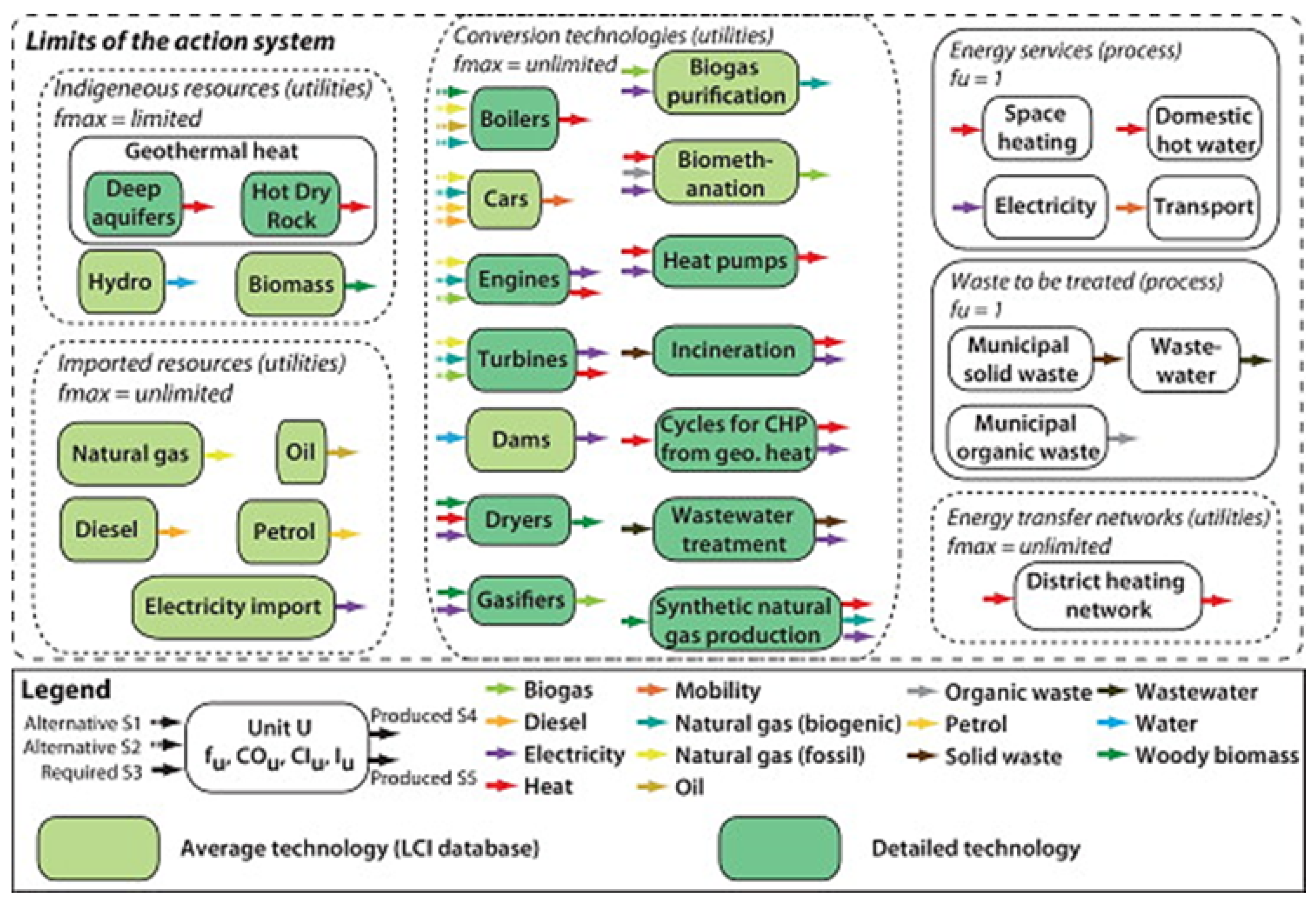
Another perspective is the use of the Life Cycle Assessment (LCA) using multi-objective optimization techniques [
14]. LCA also stresses the importance of the early phase and it is an interdisciplinary approach, integrating concepts from engineering design, ecology, sustainability, and economic and thermodynamic aspects.
Figure 3 presents the basics for this proposal. Information is organized and structured using concepts of system modeling, also redirecting energy distribution projects towards systems design engineering.
LCA is a very precise technique that goes into operational details since the initial stages and, for this exact reason, does not allow for a broader and systemic view. This leads to the anticipation of decision-making, which is a very inconvenient feature in complex projects that also requires flexibility. Additionally, it does not consider domain restrictions from the local environment where the project should be deployed, which are very important to reinforce sustainability and user interactions. Therefore, system maintenance could become more complicated. Furthermore, the proposed method is mainly oriented towards systems with a centralized provisioning of energy.
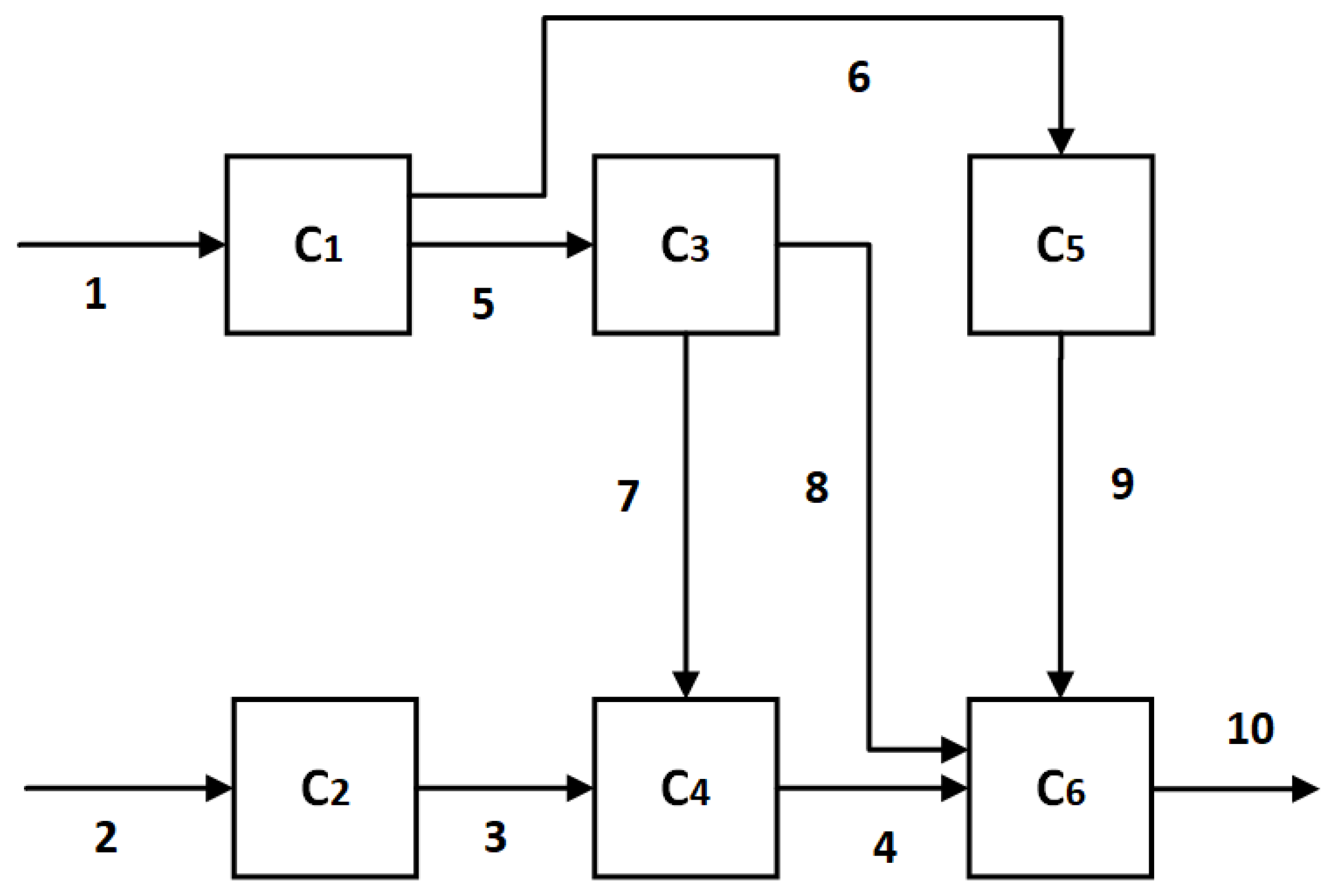
Another perspective brings a specification formalism using a requirements technique based on graph theory for modeling and verification. This reinforces the need to formalize the project from the very beginning: the requirements phase. The work was presented by Frangopoulos [
16] and proposed a method for solving energy problems with a large number of non-linear and complex degrees of freedom.
Frangupoulos presented a proposal directly based on the analysis and formal verification of requirements. However, he pointed to a design concerned exclusively with technical aspects without considering the application domain, as required in systemic approaches. Therefore, although there is a good improvement associated with the formal modeling and capture of workflow, using graph theory, aspects related to user interaction and regional insertion are not covered. It would be necessary to recover all external domain restrictions and also user interactions (as consumer and producer) from parallel documentation, either formal or informal, to complete the modeling based on graphs, as shown in
Figure 4.
We advocate the importance of a plain life cycle to energy systems, particularly related to the production/consumer distributed architecture based on smart grids. The life cycle should be based on the anticipation of a formal representation of requirements. Still, it should also allow for process analysis, domain coupling (covering both interactions and restrictions), and proper modeling of transactions with the prosumer. To avoid losing connections with the conventional methods and practitioners in the area, we also should consider a possible coupling with reference models as proposed by reliable institutions responsible for maintaining regular standards, simplifying the design process.
The Reference Models for Smart Grid Systems
There is an international effort to develop a model or architecture that is globally recognized and used by the leading players in the electricity sector which allows for the unification of methods and criteria, including the development of projects including SGs [
17].
The IEEE 2030 standard is considered the most significant recent effort to standardize architectures for the development of SG systems [
17]. In this context, the classic "V" model used in the systems area received the additional contribution of a semi-formal functional approach based on UML [
18,
19], introducing the need to insert visual diagrams from the elicitation stage and requirements analysis.
We identify current methodological trends for the power system design:
Methods are generally prescriptive, based on methodological or local regulations, but the domain (the region where the electric system will be implemented) is not included as an essential element of design;
Most methods are primarily functional, that is, they prioritize system functionality and general requirements are restricted to that, generating a severe risk of consistency due to lack (or incompleteness) of non-functional requirements;
Many methods are device-oriented, that is, they are centered on the matching to specific devices probably to facilitate the integration with legacy distribution systems, regional conditions, or users;
Many methods consider SG as a product or an arrangement of products composing the electrical system, with few or no consideration to their interaction with users;
Some approaches consider centralized master–slave systems, where SGs are individual resources tightly coupled to a master system that centralizes all control or information, basically eliminating flexibility;
In many conventional methods, the evolution of the system is not a design concern, as in systems design, which makes it difficult to introduce changes or innovations (or even to meet emerging requirements); and
Despite all the effort to standardize and build project repositories for reuse, reuse is not part of design methods.
Therefore, we conclude that a modern approach to designing energy systems requires a requirements cycle that must be closed (as a model should be), combining hierarchy with distributed system concepts. It should also be formal. Based on this, we present a proposal for a design cycle for energy multiagent-distributed systems.
Reference models have been developed to orient the design of electric systems. In the following section, we will describe only principals.
EPRI/NIST (Electric Power Research Institute/National Institute of Standards) was sponsored by IntelliGrid, while the European Commission (EC) developed the SGAM (smart grid architecture model) architecture. They are the strongest reference architectures for SG design. These architectures are based on open standards, allowing for interoperability between products and systems. Additionally, they embrace a systematic approach for addressing multidisciplinary distributed systems-based SGs, starting with a UML requirement specification. Reusability was also considered using a IEC/PAS (International Electrotechnical Commission/Public Available Specification) 62559-based repository of use-case model histories [
7,
8,
19,
20]. IntelliGrid and SGAM architectures dominated the scene both in the academy and market. Still, we should point out that they consist of a purely functional approach based on use case, as conceived for requirements elicitation rather than analysis.
SGAM architecture has a method for mapping SG use-case information through top-down layered development [
8]. Layers are derived from the use-case analysis, starting with the component, business, functional, information, and communication layers.
Basic reference models also rely on functionality and are suitable for merging conventional methods, reinforcing a longer life cycle and making the requirements analysis difficult.
3. A New Proposed Approach for SG Systems Design
The most improving design feature is to treat SG as a system, including model-based systems engineering (MBSE). The International Council on Systems Engineering defines MBSE as the formal application of modeling to support system requirements, design, analysis, verification, and validation activities, starting from the conceptual design phase and continuing throughout the development as well as later life cycle phases [
21,
22,
23]. Additionally, MBSE has several frameworks for examining different corporate system views: business view, system, technology, operations, and service [
24].
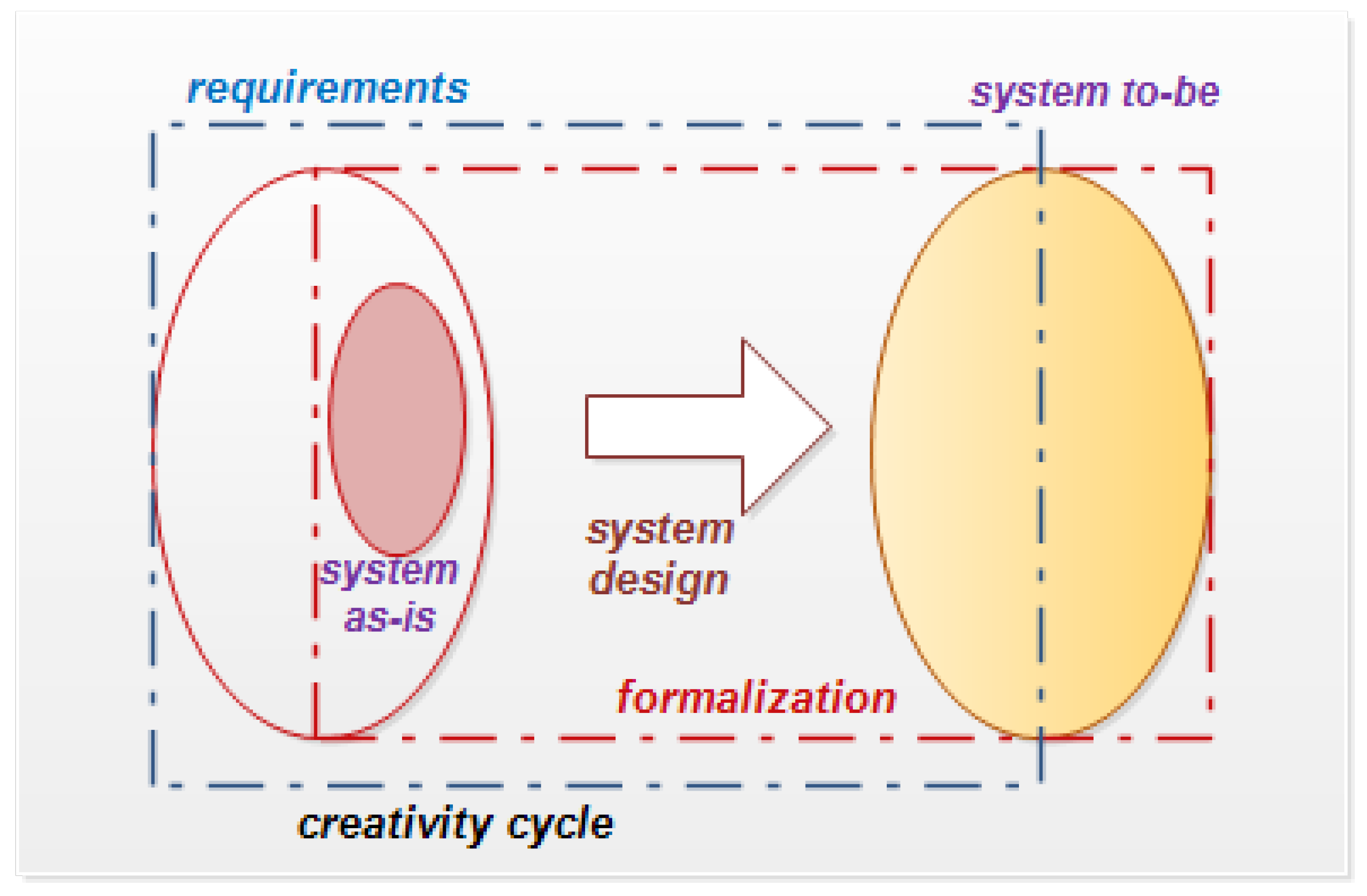
From the systems design perspective, an “ideal” design must be correct and complete, for which formalization is a crucial issue [
11]. The formal approach can clarify objectives and provide both uniqueness and closeness in the different phases of design:
In requirement (defining the what and why);
In design (defining how to satisfy the requirements efficiently with controlled costs); and
In implementation (deploying a prototype that interacts with the end-user and works properly up to decommission).
Frequently, a new system is required to “replace” an existing one that has become obsolete. The process should start by modeling the “System As-Is”, that is, the legacy system. “New requirements” should then detach the differences between the “System As-Is” and the target “System To-Be”, as shown in
Figure 5.
Another important feature is related to the paradigm shift that moves “product” systems into service systems, leading to thinking in models rather than prototypes, aiming to disconnect from the legacy functionality of their parts [
26]. Therefore, structuring a complex system means using the concept of hierarchy, that is, to divide the primary system into parts recursively until the level where components are very simple or already developed is reached.
However, a simple hierarchical approach does not help to understand a complex system. Integration is challenging and emerging requirements could appear after deployment (sometimes when the system is already being used), forcing a re-design. The hierarchy should combine loosely coupling components or services facilitating the reuse.
In this scenario, the concept of System of Systems (SoS) emerges. SoS is defined as a set of constituent systems that exist and are developed to perform specific services or tasks independently from the legacy system they work with [
27].
3.1. Smart Grid as a Distributed Arrangement of Services
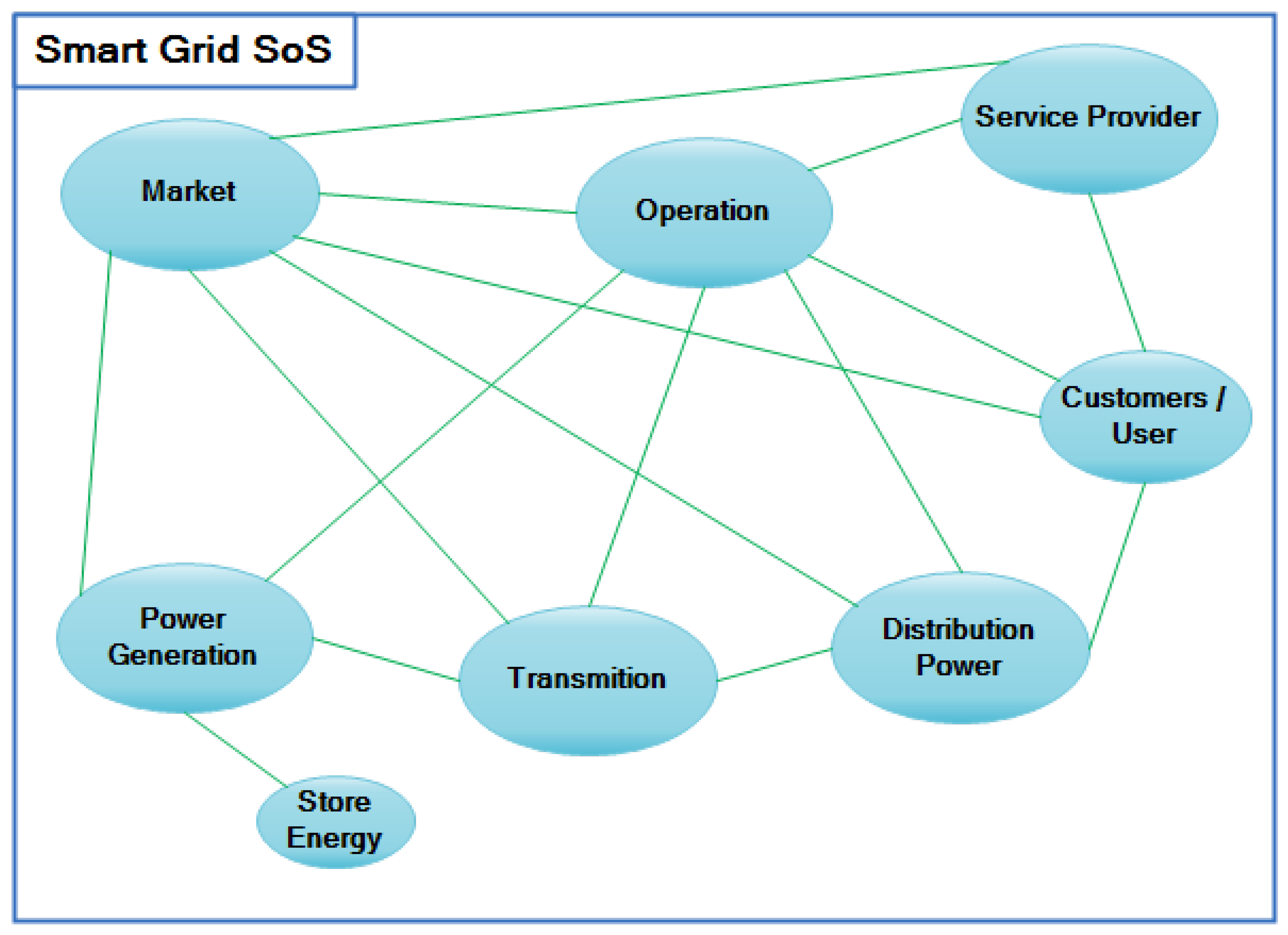
The NIST Framework and Roadmap for Smart Grid Interoperability Standards, Release 1.0, was adapted to include an SoS approach for SG.
Figure 6 shows a diagrammatic view that connects different systems (and services), implying some responsibility in the consumption or provision and including the final user in the design process. It could be interpreted as a domain functional representation, relating to operations, provision, destination, and an implicit agent responsibility.
Analyzing SG systems as an SoS [
28] leads to a model where the SG can be thought of as a “company providing energy services to different markets”. Therefore, this system’s design is hardly conceivable without strategic planning and service control management to maximize performance and optimize its functioning. Thus, technological, environmental, and socioeconomic aspects must be considered in the same perspective and be reflected upon in a knowledge model related to requirements. It necessarily points to a requirements model that transcends functionality.
Designing SG as a distributed arrangement of services in an SoS perspective requires an MBSE approach, starting with the requirements phase and going through both modeling and formalization. Such an approach should include and transcend functionality, looking for alternative methods to requirements engineering that relate to agents and map responsibility, and represent user coupling [
29].
Therefore, considering the importance of the requirements stage in SG design, we propose extending the strictly functional approach to goal-oriented requirements Engineering (GORE), exploring the possibility of providing a model-based requirements cycle.
3.2. The GORE Method for SG Systems Design
The GORE approach aims to eliminate the dichotomy between functional and non-functional requirements [
10]. Although working with functionalities sounds more intuitive, as a one-way delivering action, objectives are related to quality, user satisfaction, and feedback. Therefore, it is suitable for the user-coupling proposed in service engineering. Objectives represent the most stable information in the system and are problem-oriented, while other functional techniques are solution-oriented. Thus, objectives become an excellent communication tool with stakeholders regarding a particular problem solution.
An objective is a statement of intent that the system must satisfy through cooperation between agents, active components of the system, and those responsible for the operations behind the actions and processes [
30]. In the last decade, the GORE method’s popularity has increased, reaching a higher level of maturity [
31,
32]. The main reason for this is its capability to ease decision-making and lead to optimized solutions, different from the purely functional method, which depends on the completeness after including the non-functional requirements set.
For these reasons, we chose a goal-oriented approach for requirements elicitation, modeling, and analysis, composing a model-based requirements cycle. We also use a diagrammatic semi-formal language which is easily understood by the stakeholders [
33].
Goal-Oriented Elicitation and Modeling
Goal-oriented elicitation and modeling use a semi-formal visual language called KAOS (Knowledge Acquisition in Automated Specification) to identify business requirements, build a network of objectives and operations, and attribute responsibility to agents, associating them with goals and requirements. KAOS generates a causal visual diagram with a suit transference to a formal LTL (linear temporal logic) specification. It was developed by the University of Oregon (USA) and the University of Louvain (Belgium) in 1990 [
34].
Thus, we can construct formal LTL specifications from KAOS requirement models. Objectives are defined at different levels of abstraction, from high-level goals related to organizational, strategy, and diffusely specified objectives, to lower-level objectives with more technical, detailed, and system design-related specifications [
10].
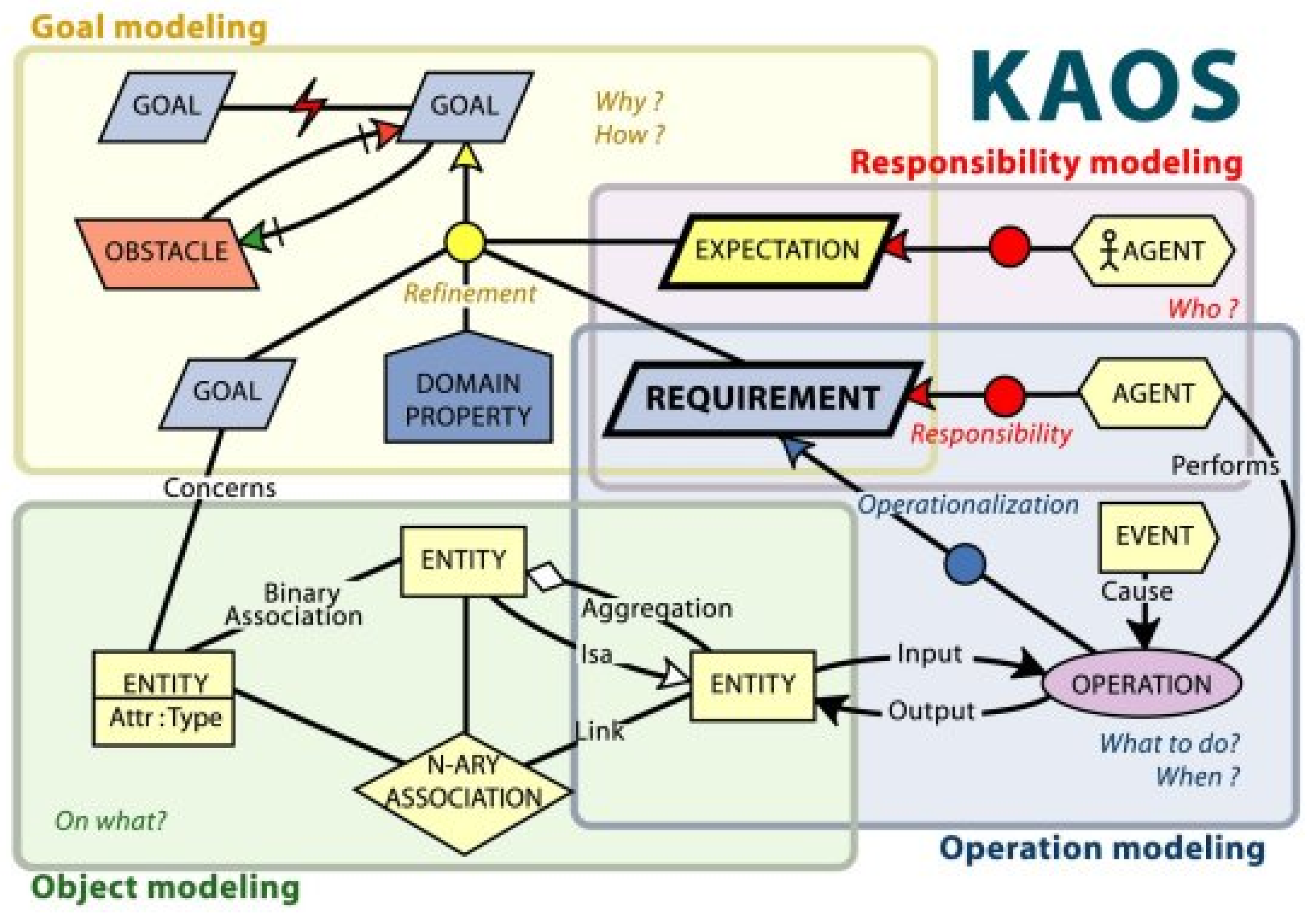
Figure 7 presents the schematic diagram of such a model.
A tree represents KAOS objectives in which the nodes represent objectives and edges represent relations (composition, refinement, dependency, and constraint).
The main objective (matching the “system goal”) abstracts the design problem, while sub-objectives represent compositional refinements or sub-goals. Expectations or intentions are related to objectives, which would not be possible in a purely functional method. Agents would stand by active objects that could change the state of the system.
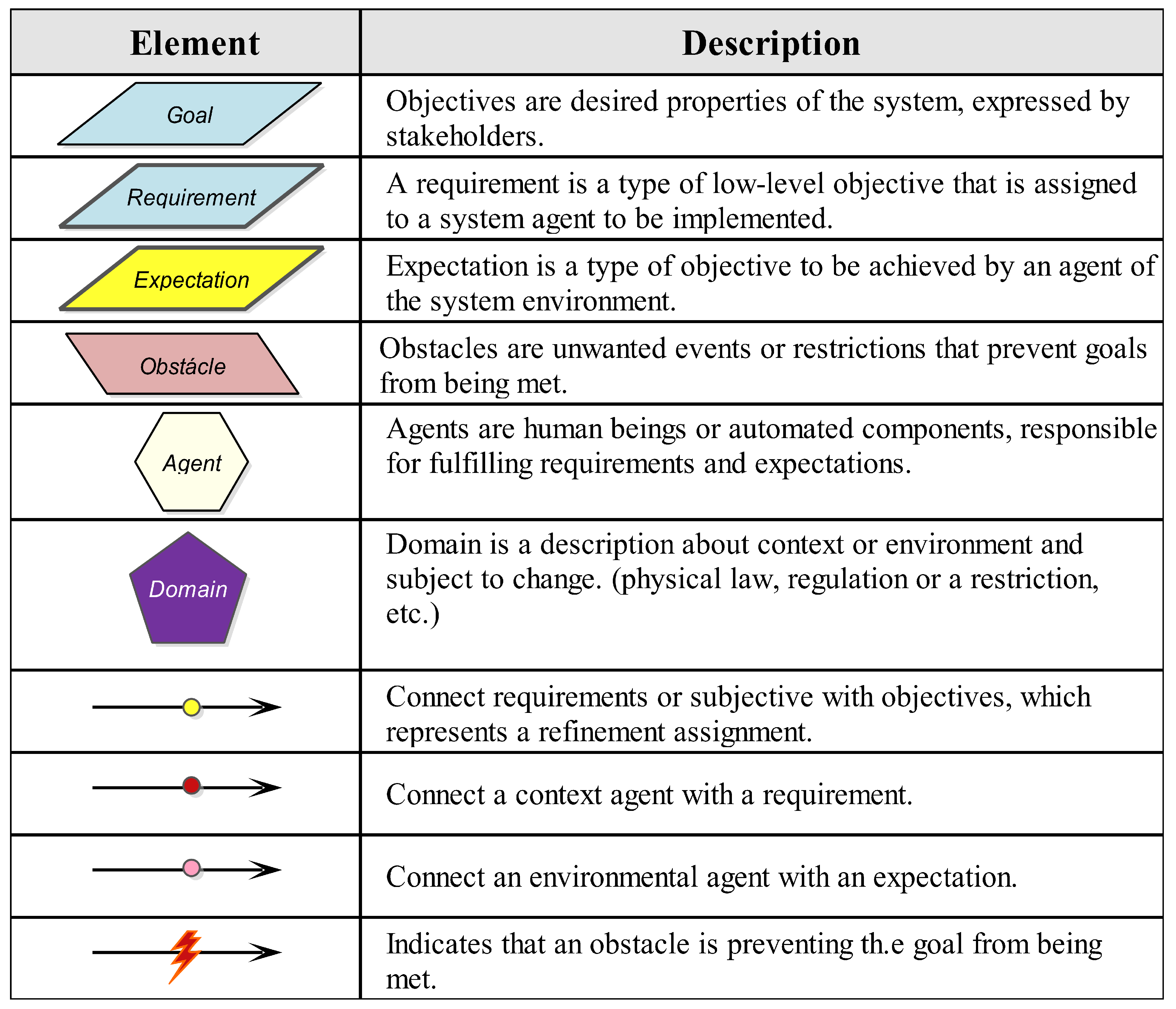
Figure 8 shows the basic elements for KAOS diagrams.
The main difference between a KAOS and UML diagram is that while KAOS integrates the requirements model in four diagrams, UML requires up to thirteen structural and twelve behavior diagrams. Although it is unnecessary to use all UML diagrams to model requirements, it raises the problem of finding a minimal set.
Regarding requirements model formalization, there is a direct algorithm to transfer KAOS diagrams’ linear temporal logic (LTL) [
36]. It is instrumental in requirements analysis, but to model automated systems, it is also necessary to use processes and a formal language capable of representing workflow, such as Petri Nets.
Some of authors worked to introduce process and workflow analyses in the requirements cycle, proposing algorithms to transfer UML [
37] or KAOS diagrams into Petri Nets [
38]. Thus, we can have a requirement cycle using UML to fit some of the reference models or use KAOS diagrams. In this work, we will explore the second option.
3.3. Verification of Requirements Based on Petri Nets
Verification is crucial to the proposed method for designing a power electronic mesh of sustainable resources integrated into a conventional electrical distribution system. The basic assumption is that requirement specifications must be formalized, analyzed, and verified before searching for an effective solution.
As with any automated system, integrated electronic power plants have to guarantee the proper convergence of objectives towards the satisfaction of user needs (as services) while also avoiding undesirable states and obstacles. This could be obtained from the modeling and verification of requirements, which would lead to the design of solutions that could also be verified using the same formalism, increasing traceability in the whole design process.
Verification could be done by generating the state space or by analyzing workflows (of control and items) using property analysis in Petri Nets, or both. Temporal and hierarchical extensions are also welcome.
4. A New Requirement Cycle for Microgrid Systems Design
We propose for a requirements cycle to be inserted in a design approach for microgrids that have the following characteristics:
Systemic vision, that is, a holistic approach where the microgrid is a service system component and therefore should be considering since the early design phase to work in the context of a more extensive and evolving system that will enforce flexibility and reusability;
The microgrid service system is built based on system goals and in a legacy system (the system-as-is);
The approach should be based on objectives, especially in the early phase (goal-oriented requirements);
The method follows service-oriented engineering, which means that the proper coupling between system and user is part of the design;
The process is recursive and distributed, allowing for the use of subsystems already developed or specifying components that will be developed later; and
Formalization should be present since the requirements phase using LTL and Petri Nets.
In this work, we will focus on the early phase. MBSE will be the overall approach to propose a requirements cycle that can specifically sustain electrical systems based on the interaction of different subsystems, namely a systems of systems (SoS). Subsystems could also be microgrids, generators, or primary power sources. Requirements are adapted to fit user profiles and preferences, and to anticipate emerging requirements and new demands raised after implementation.
We start by representing the existing system (the System As-Is) and using it as a reference to define new goals, expecting to convert it into the System To-Be. Suppose there is no system-as-is (in which case the challenge is to make a design from scratch). In that case, a model is derived from the requirements elicitation, capturing the intentions of stakeholders and final users.
The distributed system arrangement is treated as a service. Using GORE techniques will help to overcome the so-called functional dilemma: the balance between functional and non-functional requirements. The goal approach potentializes design reuse, flexibility, and maintenance while anticipating formalization accuracy.
Figure 9 shows the process, which starts by collecting data from the domain where the system is supposed to be used (including user profiles). Once the system-to-be goals are derived and synthesized in a diagrammatic model, they should be formalized in LTL or Petri Nets.
Petri Nets structural and behavioral properties can analyze the dynamic process and workflow [
37]. Verification should certify the work done and also provide directions for the new requirements cycling.
In the following, we will show the requirement cycle in a case study for a power supply system (a smart grid) installed in an isolated Amazon forest community.
5. Case Study: Energy Supply in an Isolated Community
The proposed method was applied in a case study based on the R&D Project “Minigrid with intermittent sources to serve isolated areas”, which was a project conceived by a research group and implemented in an isolated community in 2012 [
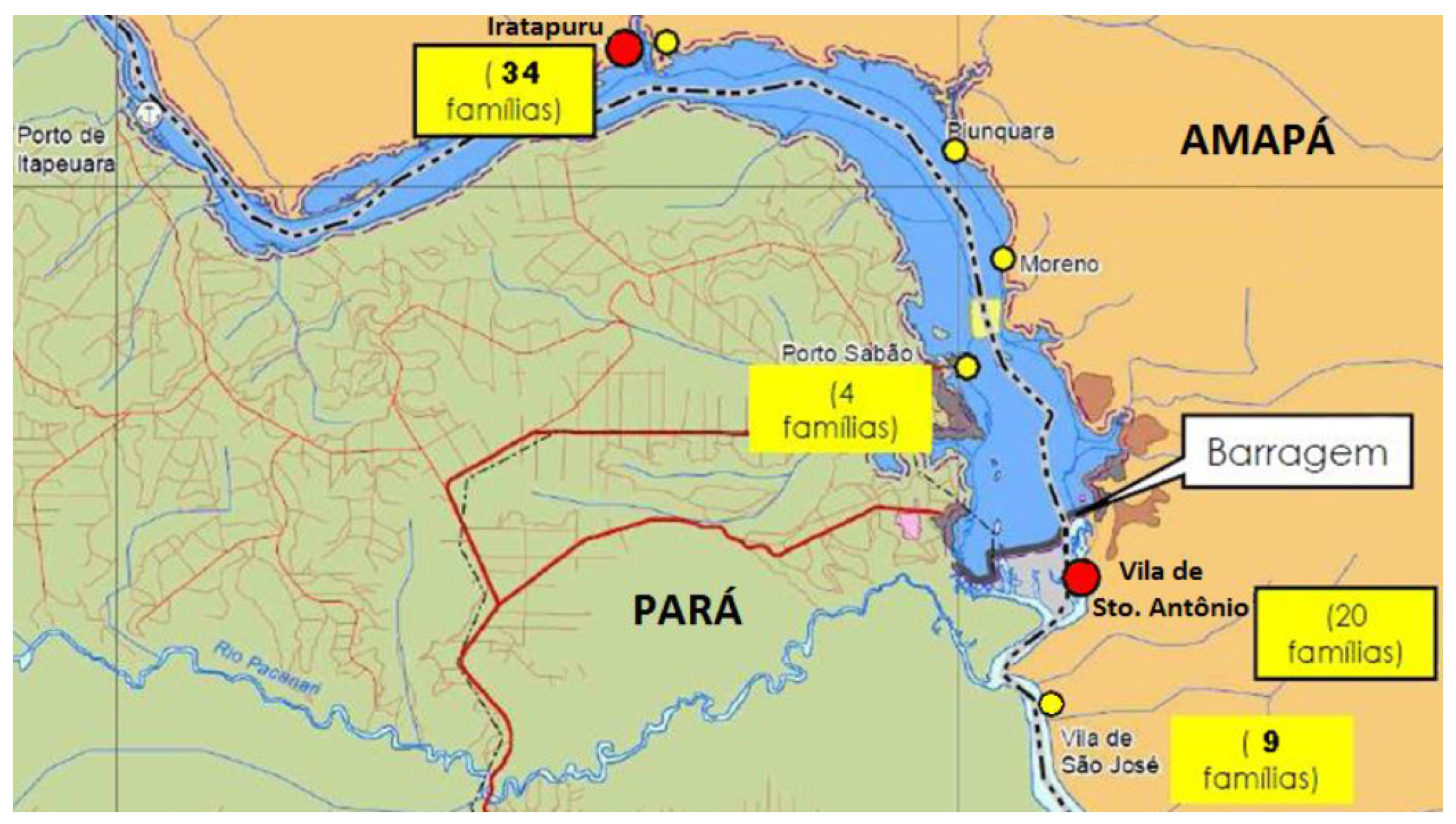
39]. The project’s main goal was to develop and implement a solar–diesel battery microgrid, which we take as the system-as-is. The implementation domain was a small community in Laranjal do Jarí, located in Amapá province, covered by the Brazilian Amazon forest (
Figure 10). In this region, many county communities are energetically isolated from the conventional hydroelectric provider.
The project was revisited to provide maintenance, that is, to attend to missed or emergent requirements and to improve automation. We detected some emerging requirements using the goal-oriented modeling built over the legacy system-as-is used to design the new system. Another goal of this maintenance process was to check and enhance sustainability and compatibility between the system and the local environment. Finally, the user coupling (originally only consumer) was also a goal, especially in terms of exploring this user’s possibility to produce energy.
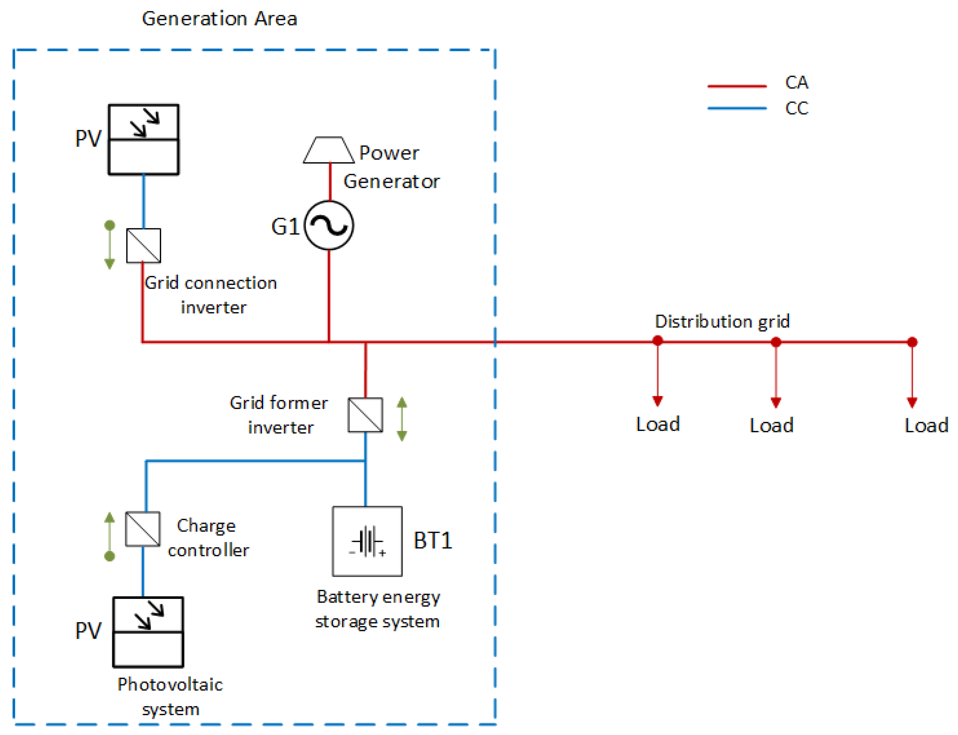
The microgrid mixed both AC and DC architecture, as shown in
Figure 11. The legacy system (system-as-is) combined intermittent solar energy with battery sources and diesel generation units in a single automated generation system. The diesel generator was a backup unit to guarantee operation when the solar source was not producing the expected charge.
A data acquisition system (DAS) for control, monitoring, and storage was embedded in the network of inverters used to provide information about the system’s behavior, such as the amount of energy generated and specific load consumption.
Energy meters monitor each customer’s consumption and show when they overtake pre-established values. The monthly energy consumption of the units was not monitored by energy meters, as the purpose was not billing.
5.1. Modeling the System-As-Is
Following the requirement cycle of
Figure 9, we started by organizing and classifying information, as shown in
Table 1. This information was used to identify and justify objectives.
Some revisiting points emerged from the analysis. Most of them were derived from the emerging requirements or changes that appearred after implementation either in the environment or in the consumer’s attitude. Such requirements would not be identified using a strictly functional approach, which justifies choosing a goal-oriented method.
The objective model for the legacy system’s (system-as-is) objectives is shown in
Figure 12. Basic information derived from the original project’s documentation but additional expectations and constrains (and conflicts) emerged from the analysis of
Table 2.
The main goal for the system-as-is was to “Provide a low voltage microgrid” and it was refined in the sub-goals successively. For instance, “Meeting operational requirements” depends on the sub-objectives “Managing energy production”, “Measuring consumption”, and the expectation “Schedule maintenance”. Requirement expectations are linked to the agents concerned with them: the Concessionaire, responsible for maintenance; the User; the Power Meter (a passive interface in the legacy system); the data acquisition system (DAS) Controller; or the financial provider (the Government). Notice that in the original project, the agent identified as “User” is responsible only for “Monitor Measurement”, that is, this agent is not a consumer (recall that the system does not charge its consumers). Consequently, the project does not identify the system and its components as a service.
5.2. Modeling the System-To-Be
We first need to identify the target problem and its relation to the execution environment to model the system-to-be. From the analysis of the system-as-is, we understand that a possible problem is related to the excessive energy consumption due to the advantages that electricity offers rather than to the technical energy losses related to the end-users’ alienation from the energy provision. Energy stealing was also a problem, motivated by changes in the user attitude.
The system’s environment does not a general provider, turning it into an isolated microgrid very dependent on the energy it could generate and responsible for its own backup to avoid interruptions.
We propose changing the domain from an isolated microgrid to a distributed microgrid (on-grid) with a higher degree of automation to solve these problems. Domain changes, such as automated measurement and new communication technologies, appear as new objectives. In addition to technical changes, the new system must be safe and reliable, and must meet all interested parties’ requirements (such as the utility, financial, and environmental agencies). In the new scenario, the user becomes a prosumer and should provide information feedback to optimize the microgrid system.
The new system can no longer be considered a “product”. Therefore, it will be necessary to prioritize the requirements of the system that provides this service.
The primary (system) goal of the system-to-be is to improve the low voltage legacy microgrid design in the Amazon region. Still, now the objective is to enhance the automation level. Emerging requirements anticipated in the system-as-is modeling appear in expectations, obstacles, or restrictions, and lead to new requirements.
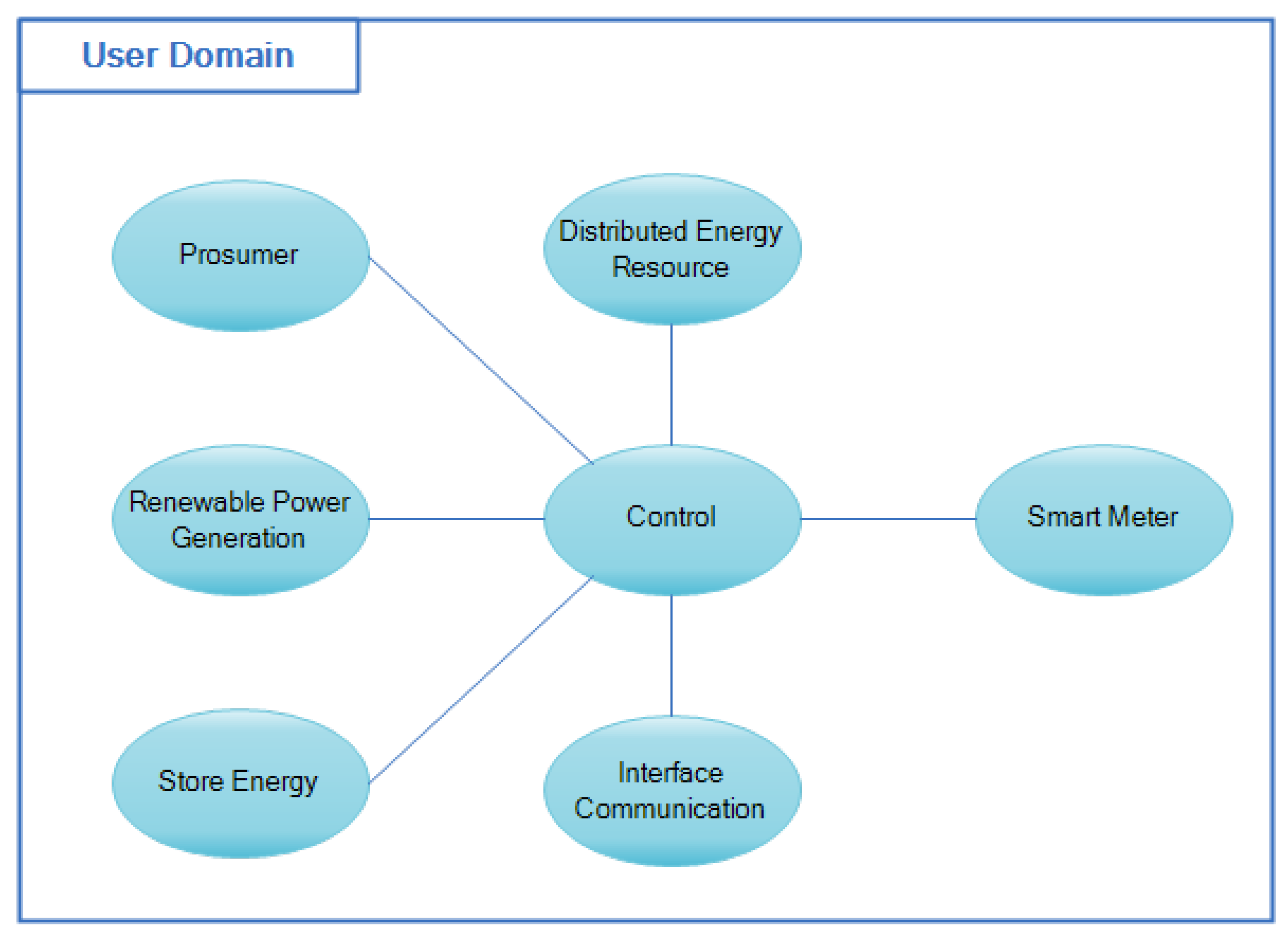
Thus, to achieve the System To-Be’s objectives, we propose a SoS+ architecture that supports a new arrangement of services (subsystems) where agents are dynamic elements. The final user is one of these dynamical elements and has a complex structure of resources, as shown in
Figure 13. One of these constituent systems is the smart meter (SM).
The system-as-is goal showed that the power supply would be blocked whenever the user consumption exceeds a pre-established limit of 100 kWH. There is no consideration of historical consumer data.
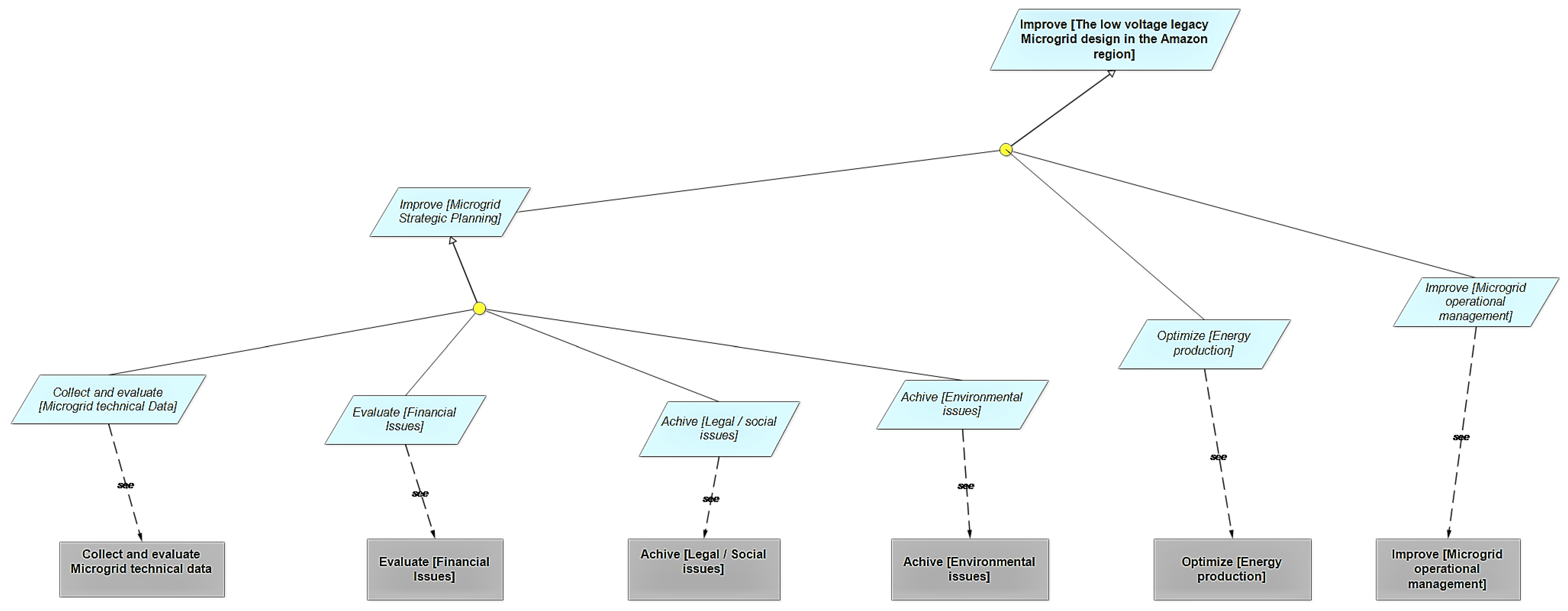
Figure 14 shows the objective diagram for the system-to-be, in which the main objective is to “Improve the low Voltage legacy Microgrid in the Amazon region”. The sub-objectives “Improving Strategic Planning”, “Optimize energy production”, and ”Improve operational management” should contribute to the achievement of this primary goal. These sub-objectives can be successively refined.
The analysis of the objective diagrams points to the need for a service system that supports a higher level of control and interaction with the prosumer. Parameters such as the energy production and consumption in each unit should be monitored, as well as its balance between provision and consumption. All data should be directed to an advanced metering infrastructure (AMI) which acts as a service provider instead of a passive supervisor. The detection of electricity stealing is a goal. Naturally, the SM should process information and commands to activate or deactivate the dealership’s energy provision.
The goal of “Reducing energy consumption” would fail if the user does not take the actions required. These actions should range from energy-saving acts to the production of energy as a prosumer. The adequate coupling with the end-user is ensured by monitoring the transaction communication.
5.2.1. The Object Model
An object model should describe all the agents that contribute to the functioning of the system service, be it humans or machines. Object modeling is also practiced in other representations, including UML, and does not constitute a novelty. It is also essential for the goal-oriented approach to support the interaction between the energy system service and its prosumers. We will further illustrate the modeling of the role of a machine, namely the smart meter.
The prosumer characteristic appears in the goal-oriented model, including the same individual prosumer as an external user (and therefore a consumer) and as part of the system (an energy service provider).
Agent modeling will also be used to support responsibility diagrams.
5.2.2. The Responsibility Model
The responsibility model maps the relationship between agents and their role in requirements satisfaction and restrictions. Building a responsibility model means analyzing different requirements and expectations, and assigning agents responsible for launching, performing, or receiving their results.
The responsibility model denotes relations where an agent can be the service provider or service consumer for modeling services. A provider or consumer relation was detailed only in the Petri Nets model since it does not belong to the current goal-oriented method.
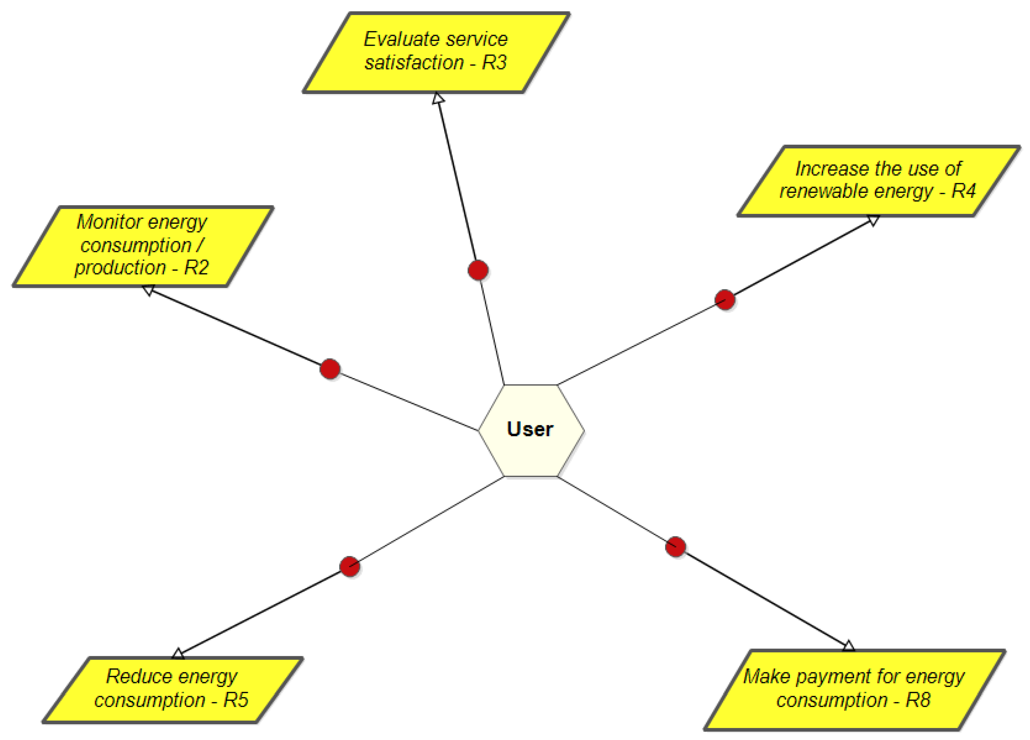
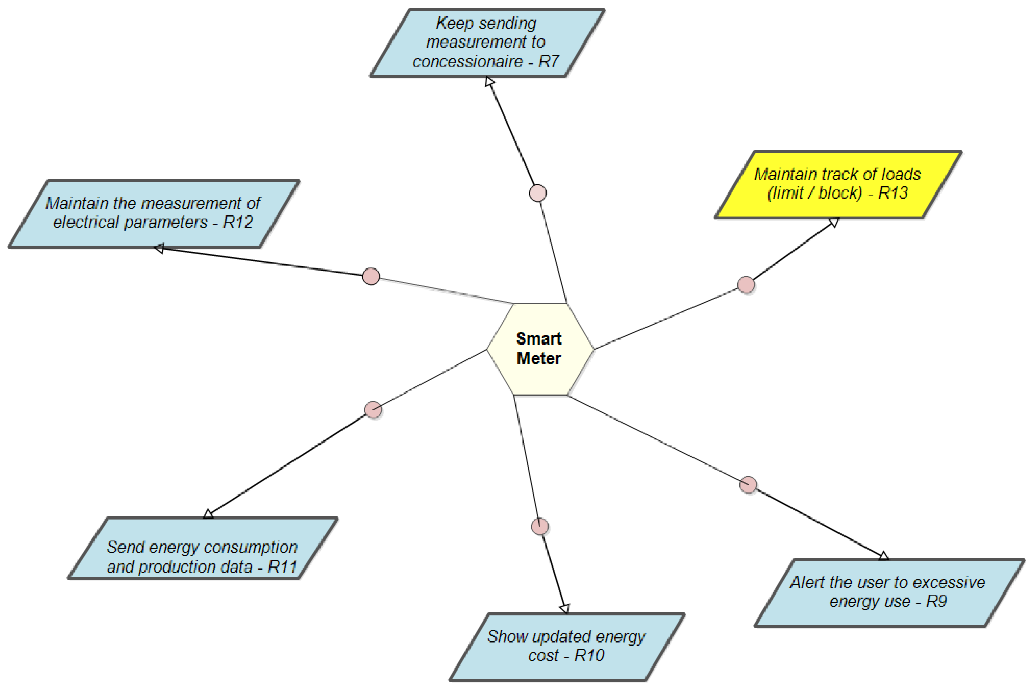
Figure 15 shows the responsibility diagram for our case study and describes both the new requirements and expectations assigned to the end user and SM agents, respectively.
5.2.3. The Operation’s Diagram
The operation’s diagram describes agents’ behavior for meeting requirements. For instance, the SM agent must fulfill the requirement “Receive information of energy consumed and produced” and the expectation “Inform the user about Energy consumed and produced”. In further maintenance, any change in the communication with the user would lead to an investigation, reprogramming, or modification of this agent.
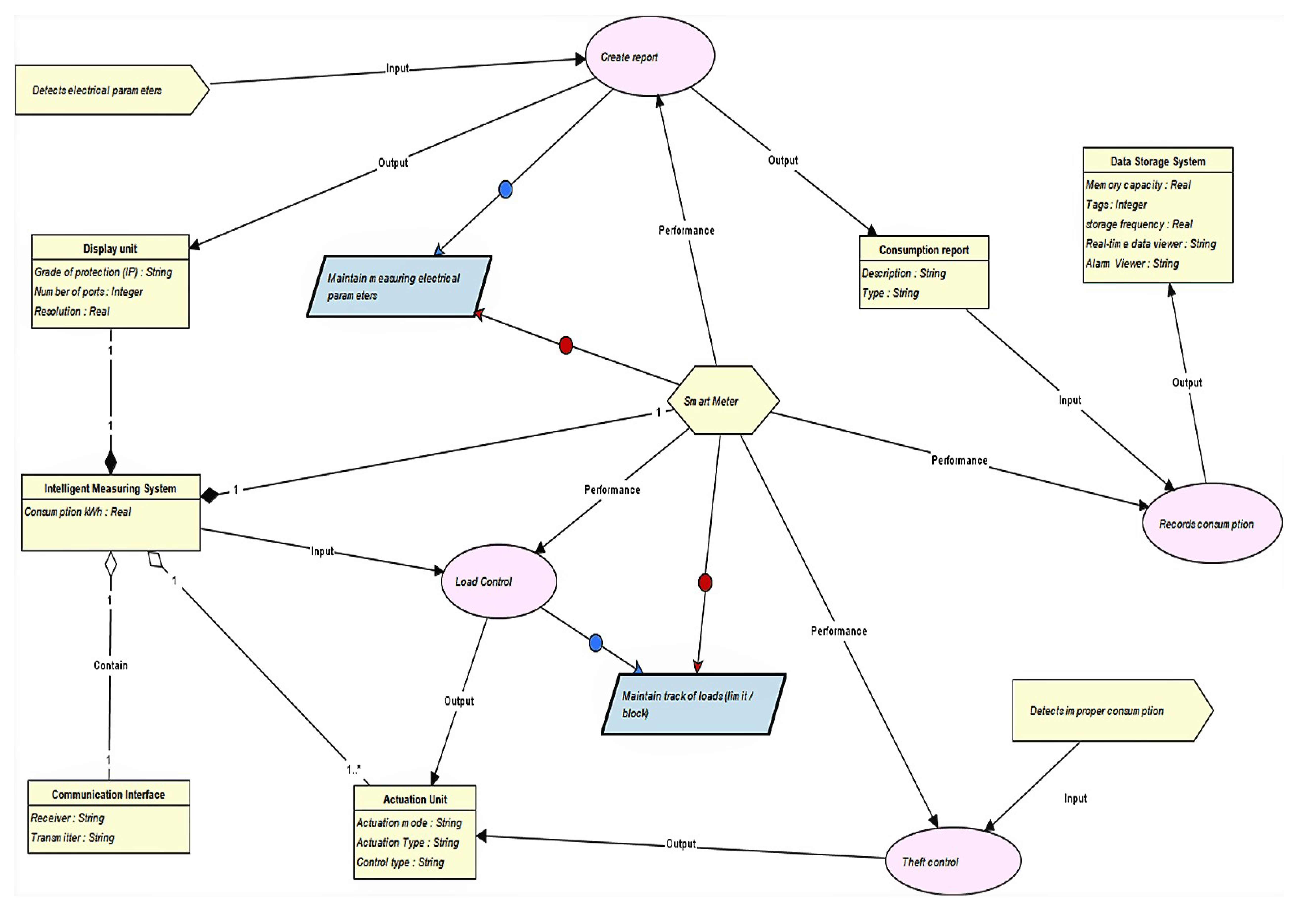
Figure 16 shows a definition for the object Smart Meter (“SM”) and
Figure 17 shows its behavior carrying out operations that affect the “Consumption report” and cause the activation of the “Register consumption” operation. It is verified that this operation has an entry called the “Measurement data received” event and the corresponding output is represented by the “Consumption report” object. The “Recorded record” event represents the end of the operation.
5.2.4. The Operation’s Diagram
The operation’s Diagram describes agents’ behavior for meeting requirements. For instance, the SM agent must fulfill the requirement “Receive information of energy consumed and produced” and the expectation “Inform the user about Energy consumed and produced”, respectively. In further maintenance, any change in the communication with the user would lead to an investigation, reprogramming, or modification of this agent.
Figure 17 also shows the “SM” behavior carrying out operations that causes the activation of the “Register consumption” operation. It is verified that this operation has an entry called “Measurement data received” event, which corresponding output is represented by the “Consumption report” object. The “Recorded record” event represents the end of the operation.
Figure 16 presents the “SM” agent’s requirements and expectations.
6. Formalizing the Requirements Model
Finally, the requirements model, composed of the objective, object, operation, and responsibility diagrams, could be transferred to a formal representation in linear temporal logic (LTL) or Petri Nets. Since we intend to work with automated processes, we will introduce a formal representation in Petri Nets, following the standard IEC 61850.
7. Analysis of the Partial Results
The outcomes of the proposed methods appear in the design process of the case study presented.
The proposed requirements cycle starts modeling the system-as-is (if a legacy system exists) to understand and analyze the current design situation. The system-as-is is scrutinized to find flaws or improvements to be inserted in the system-to-be. This part of the method is already proposed in existing material for KAOS [
35,
36,
40].
We should also point out that we applied the goal-oriented approach, delaying the expression of discrimination between functional and non-functional aspects, and always relying on goals to collapse or hide this need. We avoided the pressure to balance functional and non-functional requirements at the beginning of the process while dealing with the problem definition (not with solutions) and with incomplete knowledge. Non-functional requirements will be included as domain restrictions later.
The service design appeared in the process only heuristically and although very useful, it still needs to be formalized in further work. For instance, the current model admits direct formal modeling for users’ classes but the coupling between the service provided and the user agents was not formalized. In other words, it is essential to highlight the importance of value co-creation modeling to support (human) user interaction with the service. A formal approach for that is being developed by the authors and will be published later.
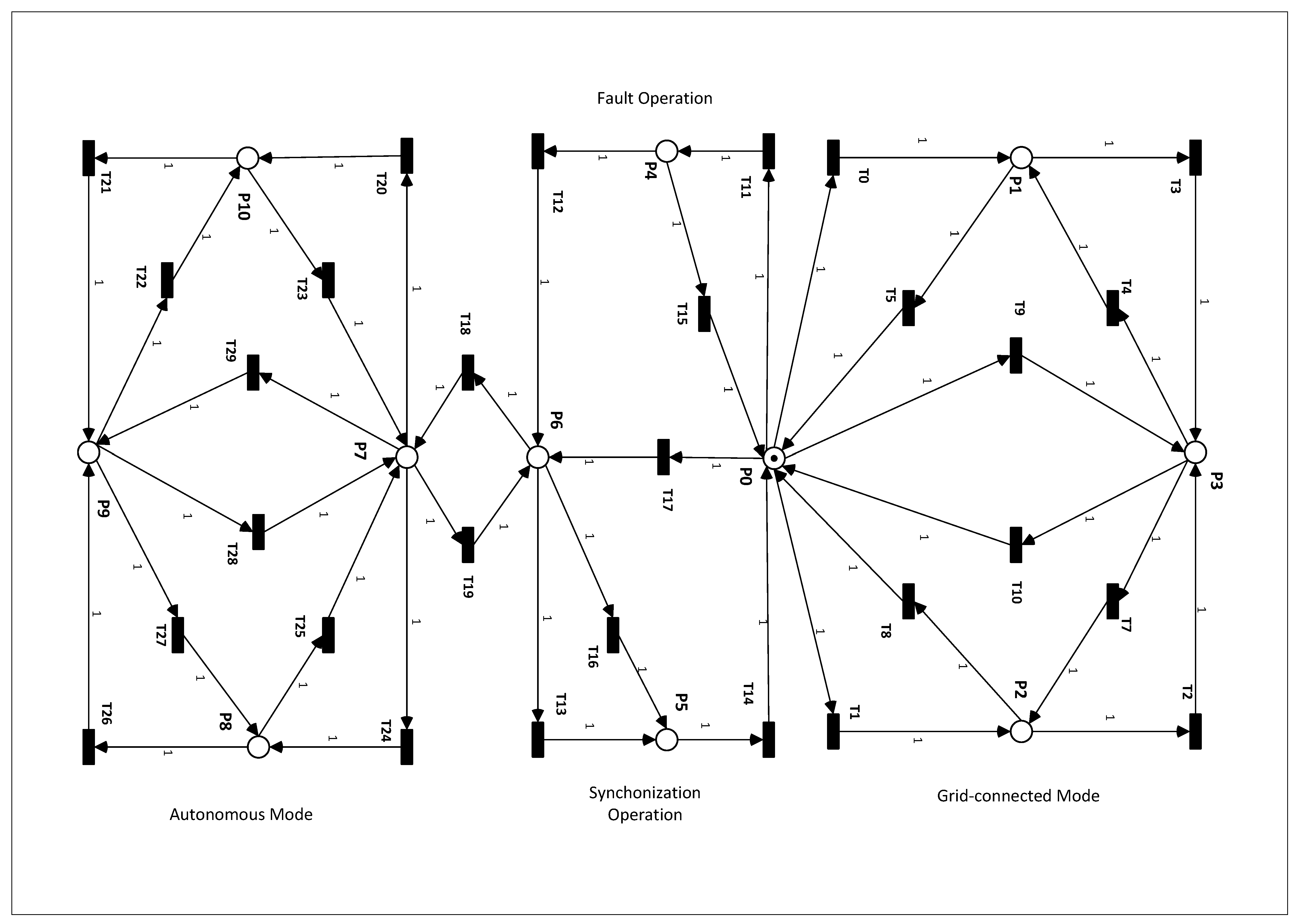
The Petri Net in
Figure 18 can be analyzed using available environments to evaluate its transition graph (as an automaton) or to perform property analysis. Either way, we can extract and verify the desired properties or detect some unexpected behavior that should be removed from the control/service system. A Petri Net is a formal schema that captures the behavioral and structural properties of a target system. It is well used in modeling automated dynamical systems. The ISO/IEC 15.909 standard provides a unified definition of the formalism used by the market and academy.
The proposed method follows a cycle of model-driven requirements development for a distributed energy service system, mapping the interaction between all agents, be it humans or machines, and its relationship with the surrounding environment. This is very helpful to ensure sustainability and human well-being as part of the design process.
8. Conclusions
This paper’s contribution is a requirement cycle that faces the growing complexity of microgrid design in sustainable environments. In such cases, the tendency is to couple the low-voltage distribution of energy [
41] with a sustainable network of prosumer units, reducing harmful interference in the environment while integrating the energy service with its prosumers. The system is open, meaning that it will be frequently used for designing, implementing, and integrating (or removing) new prosumer arrangements on top of a legacy system that minimizes long-wire transmissions, especially inside forests.
To fit this demand, we advocate that:
Distributed microgrid systems should be modeled and designed as systems or systems of systems (SoS);
Distributed microgrid systems should be designed as services or service of services (SoS+);
Distributed microgrid systems design should be modeled and formalized, allowing for a sound verification and coupling with the legacy system; and
Distributed microgrid clusters must be easily adapted and reconfigured.
To achieve these goals, we proposed a model-driven requirements life cycle based on a goal-oriented approach to model services, stressing the communication and coupling with the end-useR, which is a critical issue for the service approach. Dynamic requirements synthesized by this approach are invariant and will be preserved both in the design process and even after, up to the system elimination. Formalization as well as property and process analysis are performed in Petri Nets.
Once the focus is on the life cycle, we prefer to avoid a tedious mathematical explanation of all aspects. Instead, we chose to show the method’s practical applicability, preserving soundness. A case study based on a real application provided a suitable example: a microgrid design that needs to be expanded to a distributed smart grid service to provide energy in a small community in a tropical forest with substantial sustainability restrictions. We used its implementation as system-as-is and revised the design, leading to emergent requirements and a missing coupling with the final user. Integrating a service-oriented component with goal-oriented requirements is the main contribution of this paper, reinforcing environmental restrictions and (human) user integration.
The state-transition direct approach to represent dynamics—the main characteristic of an automated process—was introduced using a Petri Net formal representation. However, the transference from KAOS modeling to Petri Nets was not fully automated. A new development concerns creating an XML representation for KAOS that could match PNML (Petri Nets Markup Language) as defined by ISO/IEC 15.909 (which defines the Petri Net approach). In further work, we plan to introduce this automated transfer system.
A possible drawback of the proposed method is related to scalability. From one side, the intense use of hierarchy in systems design is a way to deal with scalability and the SoS (and SoS+) approach could add the possibility to analyze components separately or to reuse some of them. From the other side, exploring XML to export models and integrate documentation in XML (actually in KML, which is a Kaos Markup Language) should make this problem slightly better than in UML, even if not solving it.
Finally, some communication problems detected will be treated using the standard IEC 61850 [
42], wherein reference models must be represented appropriately in goal-oriented diagrams and translated to Petri Nets. This development was slightly shown in the case study but is not fully automated yet. The authors are also developing a software tool to do this.


