
Industrial Upper-Limb Exoskeleton Characterization: Paving the Way to New Standards for Benchmarking


Abstract
:1. Introduction
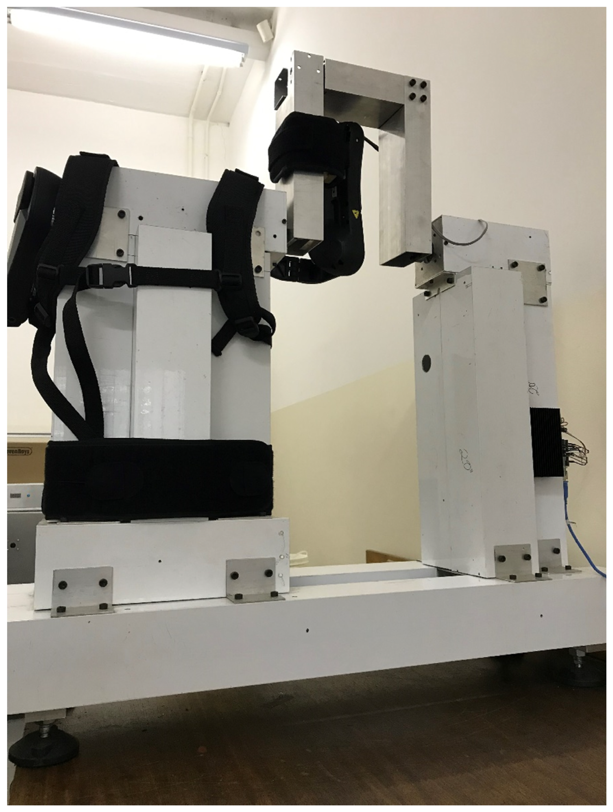
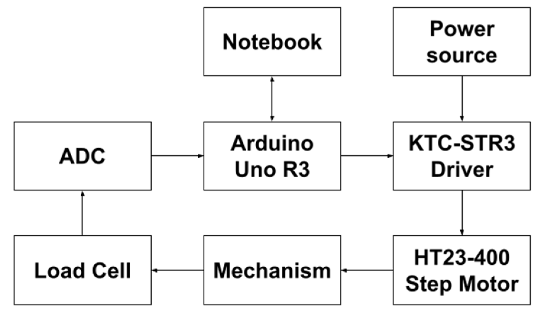
2. Materials and Methods
2.1. Masses
- M1 = 175 g;
- M2 = 109 g;
- M3 = 172 g;
- M4 = 169 g;
- M5 = 137 g;
- M6 = 103 g;
- M10 = 856 g;
- M11 = 998 g;
- M12 = 468 g.
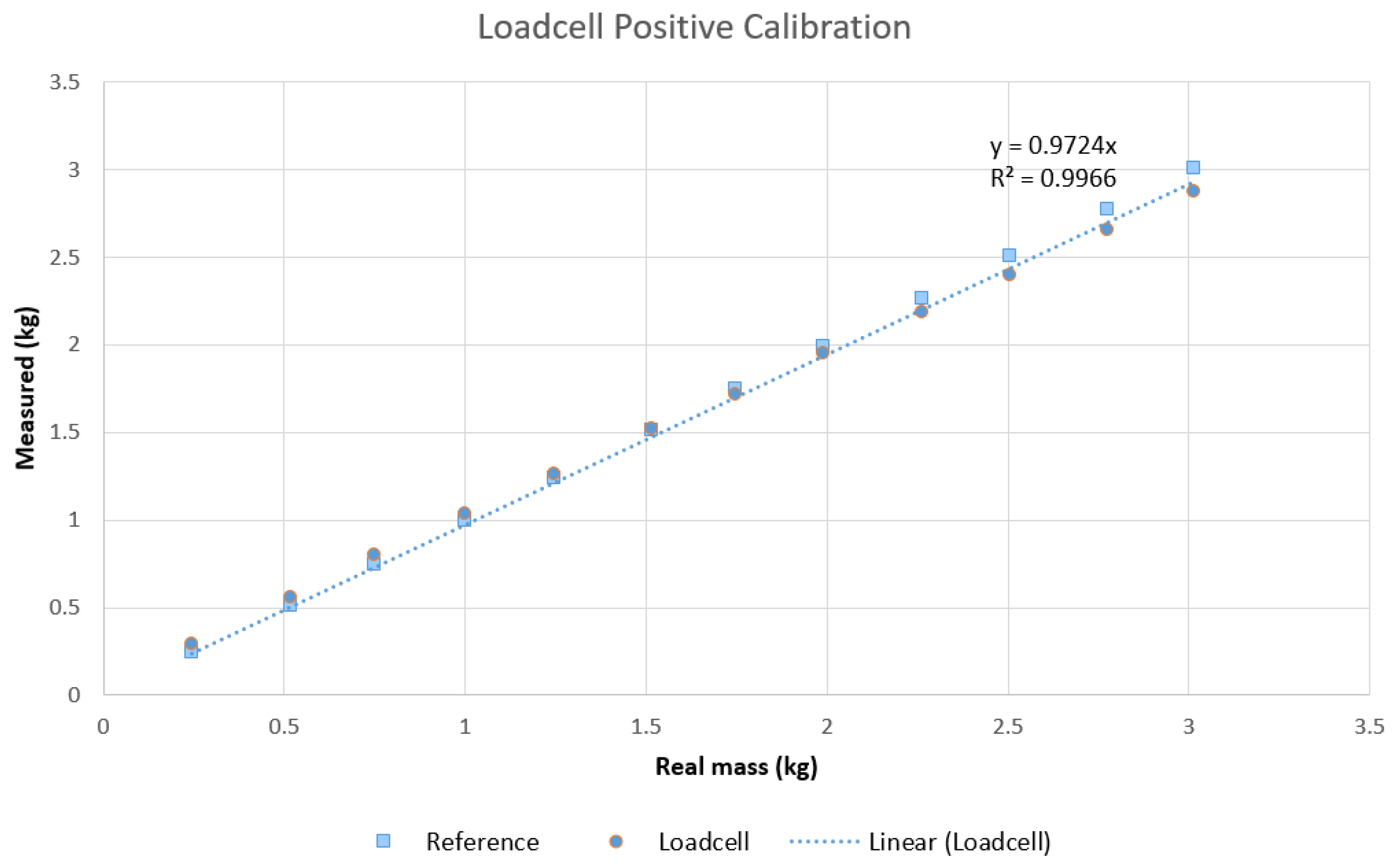
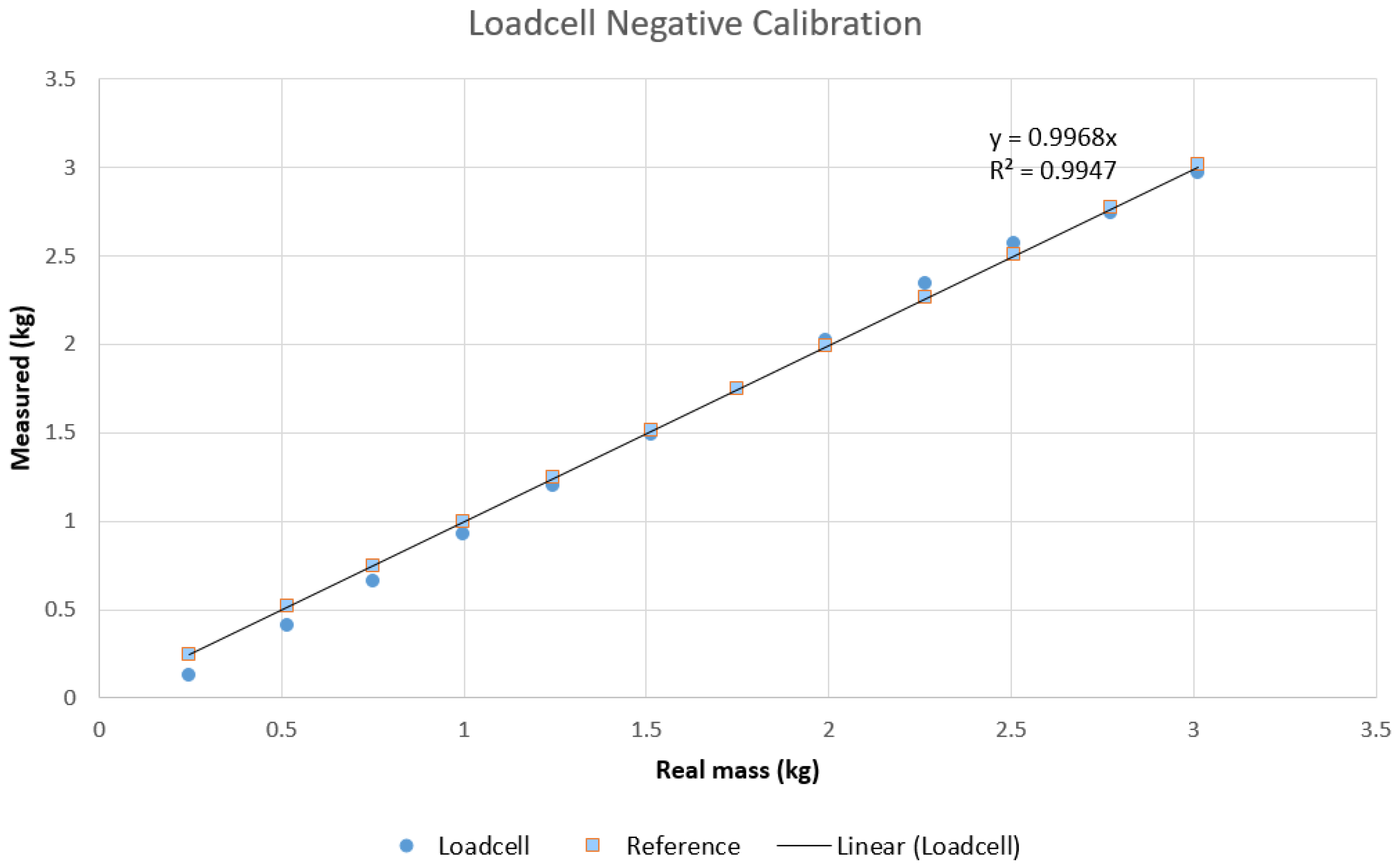
2.2. Beam Load Cell Calibration
- Positive: 233,000;
- Negative: 45,000.
2.3. Beam Load Cell Linearity
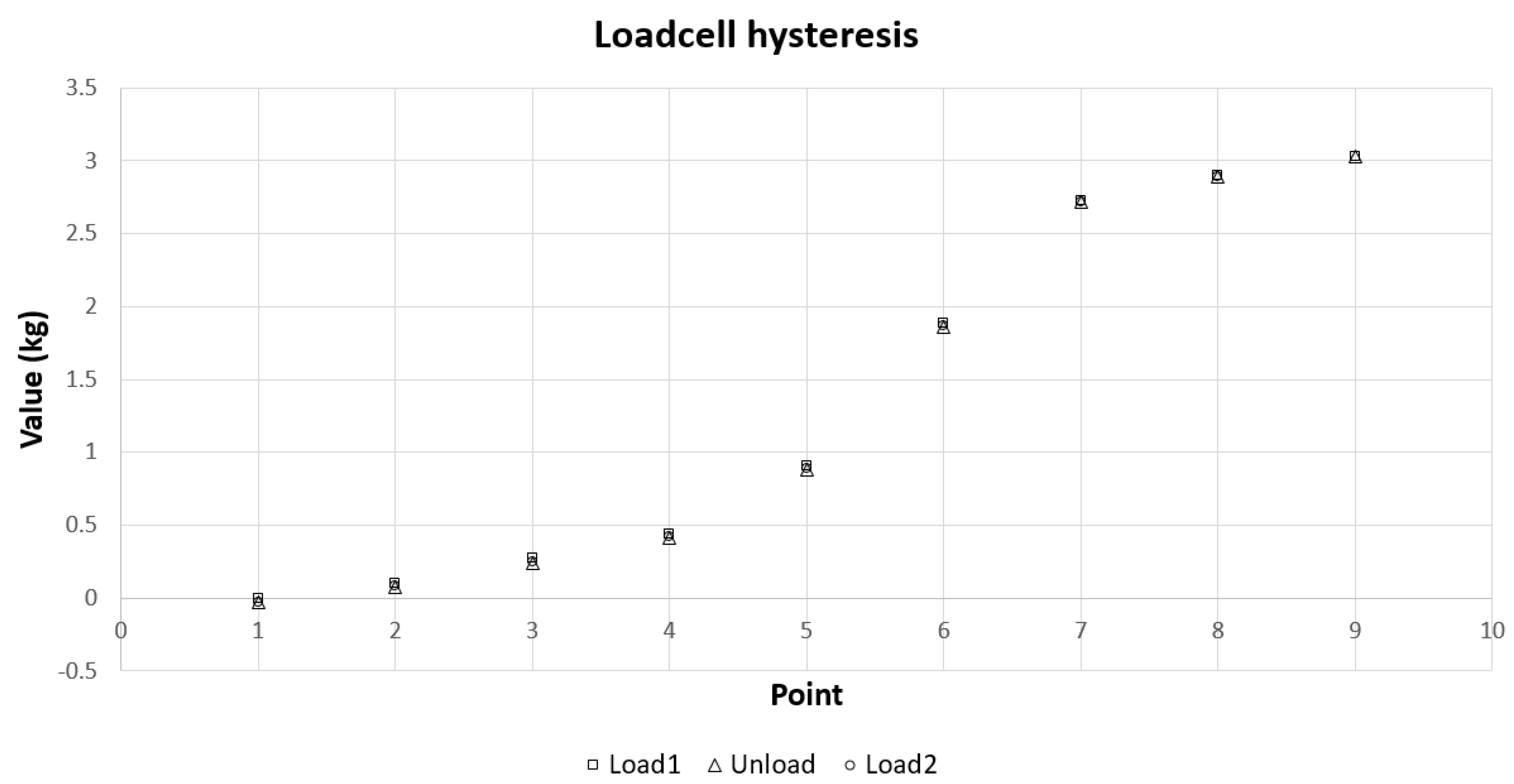
2.4. Beam Load Cell Hysteresis
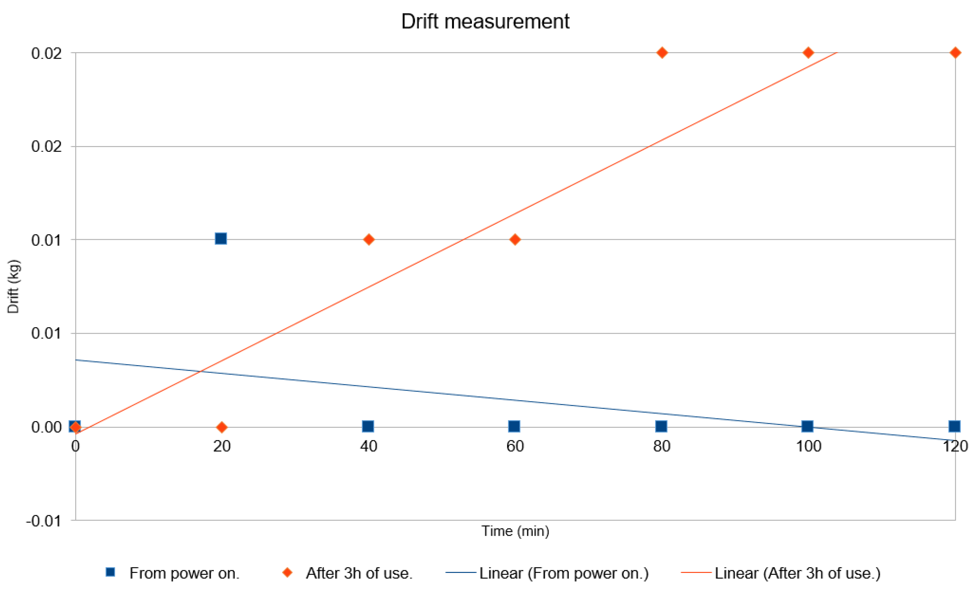
2.5. Beam Load Cell Drift
2.6. Beam Load Cell Interferences
- Effect of deflection of the table on which the workbench was laid;
- Effect of vertical vibration of the workbench;
- Effect of horizontal vibration of the workbench;
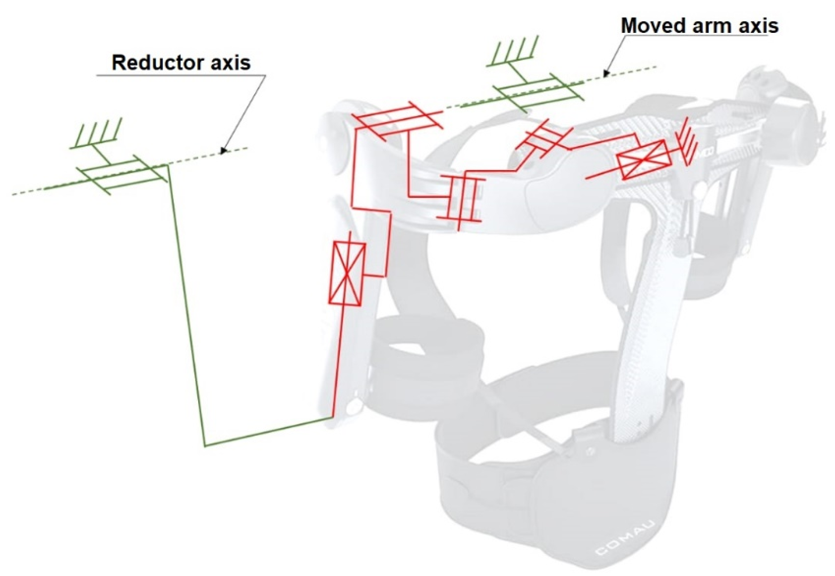
- Effect of vertical vibration of the moving arm;
- Effect of horizontal vibration of the moving arm.
- Effect of deflection of the table on which the workbench was laid: The reason for this test was that sometimes, it was necessary for the user to use the table as support for an activity. In this case, a mass of ~70 kg was placed during the measurements on the center of the largest side of the table. No change was detected in the measurement.
- Effect of vertical vibration of the workbench: The reason for this test was to check if small vibrations due to mass operation on the table could affect the measurement. In this case, a mass of ~1 kg (mass 11) was released from a height of 10 mm on the top surface of the workbench, precisely over the actuator (not a direct hit, however). No change was detected in the measurement.
- Effect of horizontal vibration of the workbench: The reason for this test was to check if small vibrations due to mass operation on the table could affect the measurement. In this case, with the help of a wire, a mass of ~1 kg (mass 11) was released from a height of 10 mm on the side surface of the workbench, precisely to the side of the actuator (not a direct hit, however). No change was detected in the measurement.
- Effect of vertical vibration of the moving arm: The reason for this test was to check if vibrations due to resonance on the arm could affect the measurement. In this case, a mass of ~1 kg (mass 11) was released from a height of 10 mm on the top surface of the actuated arm, precisely over the axis (not a direct hit, however). A change of 0.05 kg was detected in the measurement.
- Effect of horizontal vibration of the moving arm: The reason for this test was to check if vibrations due to resonance on the arm could affect the measurement. In this case, with help of a wire, a mass of ~1 kg (mass 11) was released from a height of 10 mm on the side surface of the actuated arm, precisely on the side of the axis (not a direct hit, however). A change of 0.03 kg was detected in the measurement.
2.7. Testing Procedures
3. Results
3.1. Static Tests
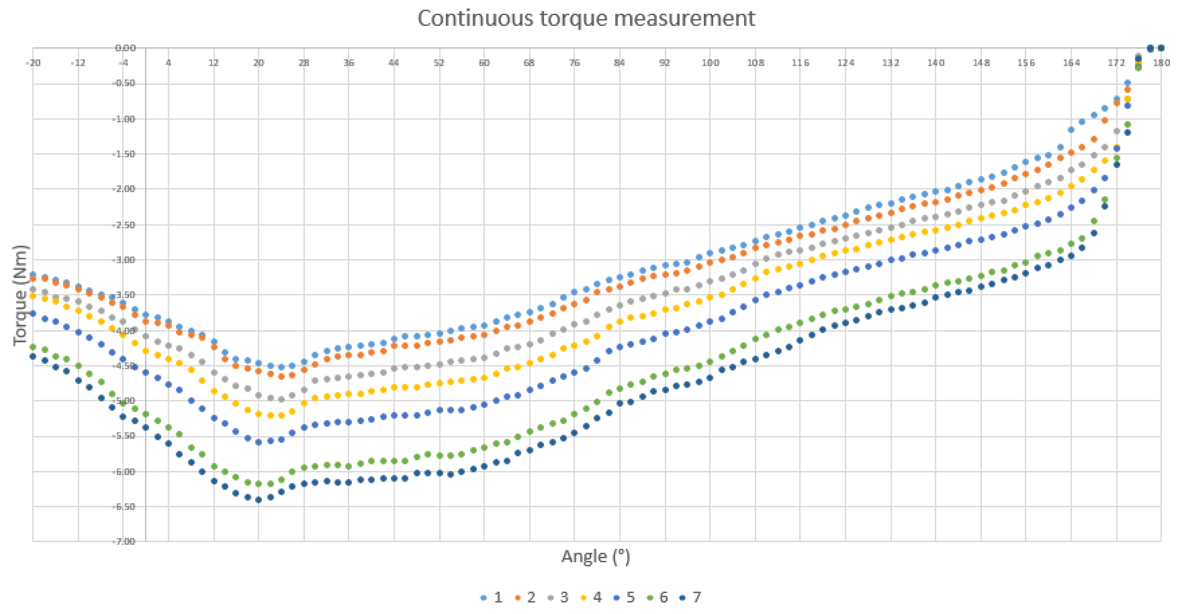
3.2. Dynamic Tests
4. Discussion
Author Contributions
Funding
Institutional Review Board Statement
Informed Consent Statement
Data Availability Statement
Acknowledgments
Conflicts of Interest
References
- Lowe, B.D.; Dick, R.B. Workplace Exercise for Control of Occupational Neck/Shoulder Disorders a Review of Prospective Studies. Environ. Health Insights 2015, 8, 75–95. [Google Scholar] [CrossRef] [Green Version]
- Maciel, V. LER e DORT São as Doenças Que Mais Acometem os Trabalhadores, Aponta Estudo—Português (Brasil). Available online: https://www.gov.br/saude/pt-br/assuntos/noticias/ler-e-dort-sao-as-doencas-que-mais-acometem-os-trabalhadores-aponta-estudo (accessed on 5 November 2021).
- SCS Fundacentro. Quase 39 Mil Trabalhadores São Afastados por LER/Dort em 2019—Português (Brasil). Available online: https://www.gov.br/fundacentro/pt-br/assuntos/noticias/noticias/2020/3/a (accessed on 5 November 2021).
- Bernard, B.P. Musculoskeletal Disorders and Workplace Factors. Natl. Inst. Occup. Saf. Health (NIOSH) 1997, 104, 97B141. [Google Scholar]
- Liberty Mutual. 2020 Workplace Safety Index: The Top 10 Causes of Disabling Injuries—Liberty Mutual Business Insurance. Available online: https://business.libertymutual.com/insights/2020-workplace-safety-index-the-top-10-causes-of-disabling-injuries/ (accessed on 5 November 2021).
- Weston, E.B.; Alizadeh, M.; Knapik, G.G.; Wang, X.; Marras, W.S. Biomechanical evaluation of exoskeleton use on loading of the lumbar spine. Appl. Ergon. 2018, 68, 101–108. [Google Scholar] [CrossRef] [PubMed]
- SuitX. ShoulderX|suitX. Available online: https://www.suitx.com/shoulderx (accessed on 11 June 2019).
- Lowe, B.D.; Billotte, W.G.; Peterson, D.R. ASTM F48 Formation and Standards for Industrial Exoskeletons and Exosuits. IISE Trans. Occup. Ergon. Hum. Factors 2019, 7, 230–236. [Google Scholar] [CrossRef] [PubMed]
- de Looze, M.P.; Krause, F.; O’Sullivan, L.W. The Potential and Acceptance of Exoskeletons in Industry. In Wearable Robotics: Challenges and Trends; Volume 16: Biosystems & Biorobotics; González-Vargas, J., Ibáñez, J., Contreras-Vidal, J., van der Kooij, H., Pons, J., Eds.; Springer: Cham, Switzerland, 2017. [Google Scholar] [CrossRef]
- Howard, J.; Murashov, V.V.; Lowe, B.D.; Lu, M.L. Industrial exoskeletons: Need for intervention effectiveness research. Am. J. Ind. Med. 2020, 63, 201–208. [Google Scholar] [CrossRef] [PubMed]
- Crowell, H.P.; Park, J.-H.; Haynes, C.A.; Neugebauer, J.M.; Boynton, A.C. Design, Evaluation, and Research Challenges Relevant to Exoskeletons and Exosuits: A 26-Year Perspective From the U.S. Army Research Laboratory. IISE Trans. Occup. Ergon. Hum. Factors 2019, 7, 199–212. [Google Scholar] [CrossRef]
- Van Dijsseldonk, R.B.; van Nes, I.J.W.; Geurts, A.C.H.; Keijsers, N.L.W. Exoskeleton home and community use in people with complete spinal cord injury. Sci. Rep. 2020, 10, 15600. [Google Scholar] [CrossRef] [PubMed]
- Daunoraviciene, K.; Adomaviciene, A.; Grigonyte, A.; Griškevičius, J.; Juocevicius, A. Effects of robot-assisted training on upper limb functional recovery during the rehabilitation of poststroke patients. Technol. Health Care 2018, 26, 533–542. [Google Scholar] [CrossRef] [PubMed] [Green Version]
- Varghese, R.J.; Freer, D.; Deligianni, F.; Liu, J.; Yang, G.Z. Wearable Robotics for Upper-Limb Rehabilitation and Assistance; Elsevier Inc.: London, UK, 2018. [Google Scholar]
- Der Vorm, V.; Sullivan, J.O.; Nugent, R.; De Looze, M. Considerations for Developing Safety Standards for Industrial Exoskeletons New Hybrid Production Systems in Advanced Factory Environments Based on New Human-Robot Interactive Cooperation. 2015. Available online: www.robo-mate.eu (accessed on 11 June 2019).
- Fox, S.; Aranko, O.; Heilala, J.; Vahala, P. Exoskeletons: Comprehensive, comparative and critical analyses of their potential to improve manufacturing performance. J. Manuf. Technol. Manag. 2020, 31, 1261–1280. [Google Scholar] [CrossRef] [Green Version]
- de Vries, A.W.; de Looze, M.P. The Effect of Arm Support Exoskeletons in Realistic Work Activities: A Review Study. J. Ergon. 2019, 9, 255. [Google Scholar] [CrossRef]
- Alabdulkarim, S.; Nussbaum, M.A. Influences of different exoskeleton designs and tool mass on physical demands and performance in a simulated overhead drilling task. Appl. Ergon. 2019, 74, 55–66. [Google Scholar] [CrossRef] [PubMed]
- Pinho, J.P.; Taira, C.; Parik-Americano, P.; Suplino, L.O.; Bartholomeu, V.P.; Hartmann, V.N.; Umemura, G.S.; Forner-Cordero, A. A comparison between three commercially available exoskeletons in the automotive industry: An electromyographic pilot study. In Proceedings of the IEEE/RAS-EMBS International Conference on Biomedical Robotics and Biomechatronics (BioRob), New York, NY, USA, 29 November–1 December 2020; pp. 246–251. [Google Scholar] [CrossRef]
- Pinho, J.P.; Parik Americano, P.; Taira, C.; Pereira, W.; Caparroz, E.; Forner-Cordero, A. Shoulder muscles electromyographic responses in automotive workers wearing a commercial exoskeleton. In Proceedings of the Annual International Conference of the IEEE Engineering in Medicine and Biology Society (EMBC), Montreal, QC, Canada, 20–24 July 2020; pp. 4917–4920. [Google Scholar] [CrossRef]
- MacDougall, W. Industrie 4.0: Smart Manufacturing for the Future. In Germany Trade & Invest; Gesellschaft für Außenwirtschaft und Standortmarketing mbH.: Berlin, Germany, 2014; p. 40. [Google Scholar]
- Manna, S.K.; Dubey, V.N. Comparative study of actuation systems for portable upper limb exoskeletons. Med. Eng. Phys. 2018, 60, 1–13. [Google Scholar] [CrossRef] [PubMed]
- Pesenti, M.; Antonietti, A.; Gandolla, M.; Pedrocchi, A. Towards a functional performance validation standard for industrial low-back exoskeletons: State of the art review. Sensors 2021, 21, 808. [Google Scholar] [CrossRef] [PubMed]
- O’Sullivan, L.; Nugent, R.; van der Vorm, J. Standards for the Safety of Exoskeletons Used by Industrial Workers Performing Manual Handling Activities: A Contribution from the Robo-Mate Project to their Future Development. Procedia Manuf. 2015, 3, 1418–1425. [Google Scholar] [CrossRef] [Green Version]
- Hartmann, V.N.; de Rinaldi, D.M.; Taira, C.; Pinho, J.P.; Forner-Cordero, A. Design of a torque measurement unit for upper limbs industrial exoskeletons. In Proceedings of the 2021 4th IEEE/IAS International Conference on Industry Applications (INDUSCON), São Paulo, Brazil, 16–18 August 2021; pp. 1005–1010. [Google Scholar] [CrossRef]


| Condition | Effect |
|---|---|
| Beam load cell calibration | Compensate for both directions. |
| Beam load cell linearity | Linear in both directions. |
| Beam load cell hysteresis | Negligible. |
| Beam load cell drift | Negligible. |
| Table deflection | Negligible. |
| Vertical vibration | Negligible. |
| Horizontal vibration | Negligible. |
| Vertical resonance | Limit test speed. |
| Horizontal resonance | Limit test speed. |
| Effect of masses | Negligible. |
| Point (g) | Masses | Exact Value (g) |
|---|---|---|
| 0 | None | 0 |
| 250 | 2, 5 | 246 |
| 500 | 1, 3, 4 | 516 |
| 750 | 2, 3, 12 | 749 |
| 1000 | 11 | 998 |
| 1250 | 2, 5, 11 | 1244 |
| 1500 | 1, 3, 4, 11 | 1514 |
| 1750 | 2, 3, 11, 12 | 1747 |
| 2000 | 5, 10, 11 | 1990 |
| 2250 | 4, 5, 6, 10, 11 | 2263 |
| 2500 | 1, 3, 4, 5, 10, 11 | 2506 |
| 2750 | 2, 3, 4, 10, 11, 12 | 2773 |
| 3000 | 2, 3, 4, 5, 6, 10, 11, 12 | 3013 |
| Condition | Reference (kg) | Worst Case (kg) |
|---|---|---|
| Table deflection | 0.00 | 0.00 |
| Vertical vibration | 0.00 | 0.00 |
| Horizontal vibration | 0.00 | 0.00 |
| Vertical resonance | 0.00 | 0.05 |
| Horizontal resonance | 0.00 | 0.03 |
Publisher’s Note: MDPI stays neutral with regard to jurisdictional claims in published maps and institutional affiliations. |
© 2021 by the authors. Licensee MDPI, Basel, Switzerland. This article is an open access article distributed under the terms and conditions of the Creative Commons Attribution (CC BY) license (https://creativecommons.org/licenses/by/4.0/).
Share and Cite
Hartmann, V.N.; Rinaldi, D.d.M.; Taira, C.; Forner-Cordero, A. Industrial Upper-Limb Exoskeleton Characterization: Paving the Way to New Standards for Benchmarking. Machines 2021, 9, 362. https://doi.org/10.3390/machines9120362
Hartmann VN, Rinaldi DdM, Taira C, Forner-Cordero A. Industrial Upper-Limb Exoskeleton Characterization: Paving the Way to New Standards for Benchmarking. Machines. 2021; 9(12):362. https://doi.org/10.3390/machines9120362
Chicago/Turabian StyleHartmann, Vitor Neves, Décio de Moura Rinaldi, Camila Taira, and Arturo Forner-Cordero. 2021. "Industrial Upper-Limb Exoskeleton Characterization: Paving the Way to New Standards for Benchmarking" Machines 9, no. 12: 362. https://doi.org/10.3390/machines9120362