1. Introduction
Straw is an appendage in the food production process. If it is not handled correctly, it will bring a lot of trouble to labor production and life [
1,
2]. Statistics show that the total weight of straw produced in the world reaches 200 million tons per year, with disposal methods including recycling, direct return to the field, burn or discard [
3,
4], as shown in
Figure 1. Burning the straw will cause environmental pollution and increase the chances of respiratory diseases [
5,
6]. In recent years, recycling straw has become a popular way of disposal nowadays. The recycled straw becomes one of the most popular sustainable materials as it can be reprocessed and used as feed, fertilizer, fuel, construction material and biomass material [
7,
8,
9,
10]. More importantly, recycled straw can reduce environmental pollution and alleviate energy scarcity [
11,
12].
Baling is a viable method of collecting, transporting, and storing straw, which is an effective way to reduce costs [
13]. The operation of the baler requires a tractor for driving. According to the shape of the straw bale after work, the baler in the market can be divided into square balers and round balers [
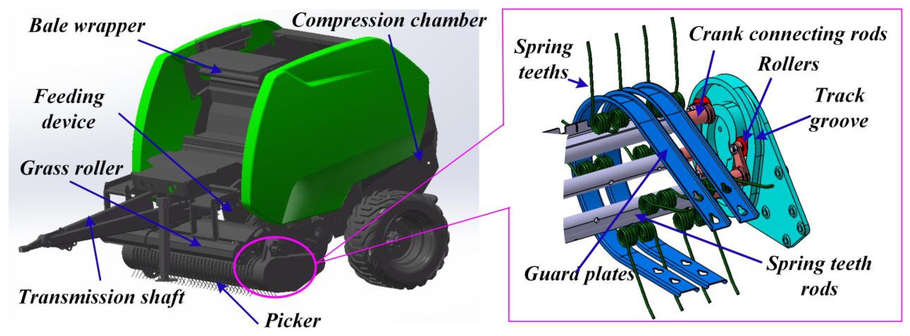
14]. Due to its advantages, the round baler has gradually become the mainstream of the market. As shown in
Figure 2, the round baler is mainly composed of transmission shaft, picker, bale wrapper, feeding device, grass roller and compression chamber. As a key component of the baler, the picker is mainly used for picking, pushing and throwing the straw. The picker is mainly composed of spring teeth, track groove, crank connecting rods, rollers, guard plates and fixed plate. The two ends of the crank connecting rod are connected to the spring teeth rod and the roller, and the rollers moves in the track groove. The role of the fixed disk is to drive the spring teeth rods and rollers along the track groove track movement. As the first process of baler operation and in direct contact with the ground, the picker has problems such as blockage and low service life.
With the rapid development of smart agriculture, unmanned tractor-driven machinery has become a popular tool to carry out agriculture-related work, and it is necessary to find the right operating parameters and to build a highly reliable machine. The picker, as a key component that affects the reliability of baler operation, in order to improve its operational performance, intensive researches have been carried out. Zhong et al. determined the operating parameters of the picker through theoretical calculation methods and designed a crawler packer [
3]. In [
15], bench tests were used to explore the relationship between the picker rotation speed, forward velocity (FV), moisture content and picking-up performance and power consumption. In addition, the track groove of the picker is parameterized by MATLAB software [
16]. Ding et al. proposed a theoretical calculation method for the movement characteristics of the picker [
17]. Xu et al. optimized the structural parameters of the multi-element spring tooth peanut picker [
18]. In [
19], a compound operation machine suitable was designed for rice straw collection and continuous bundling. Note that the above studies show that a series of results have been achieved for the structural optimization of the picker, but most of the previous research methods were conducted for the original stubble ground environment, using a single simulation or bench test to carry out the relevant tests. Since the operating performance of machinery cannot be predicted, not only will an increase in the development cost and cycle time of the implementations occur, but also the prediction of the mutual impact between the components becomes difficult.
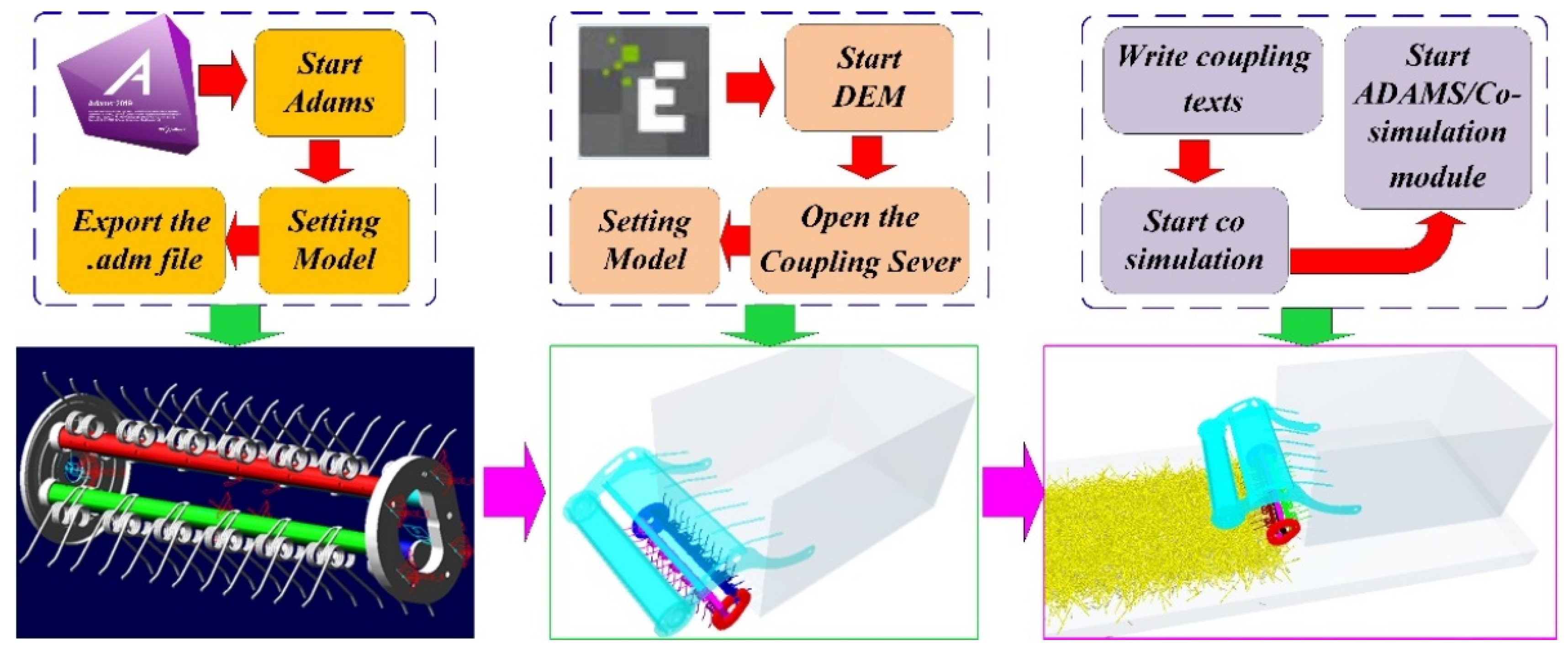
The use of multi-body dynamics (MBD) software to simulate complex motion between components is widely used in related fields [
20]. In addition, the discrete element method (DEM) is widely recognized in the agricultural field, primarily used to simulate different shapes of straw models [
21]. The picker has complex motion characteristics, it is difficult to simulate the straw picking process by using a single MBD or DEM. With the rapid development of computer technology, combining the respective advantages of MBD and DEM software to establish a coupled simulation method has been verified in related fields. For example, Christian Richter et al. carried out many experiments to verify the accuracy of the coupled simulation method and proposed the advantages of the coupled simulation [
22]. M. Javad et al. carried out a multi-objective optimization of the ship unloader grabs and used the method of MBD-DEM coupling simulation to verify the advantages of the optimized claws [
23]. Su et al. used the automatic dynamic analysis of mechanical systems (ADAMS)-DEM method to carry out the impact energy absorption and adhesion of the space robot bionic buffer system [
24]. The above research proves the effectiveness of the coupling simulation method. This novel coupled method can reduce time and economic costs compared to traditional bench and field testing methods, and identify weaknesses in mechanical systems more quickly and clearly. Motivated by the above studies, this paper applies the unique advantages of MBD software and DEM software to carry out the coupled simulation study of baler pickers. This not only allows to obtain the operational performance of the picker, identify its problems and provide guidance for the next optimization and development but also provides a reference for the coordinated operation of the unmanned tractor and baler, reducing the R&D cost of equipment.
In this paper, a new coupling method of ADAMS-DEM simulation is established based on multi rigid body dynamics modeling. A coupled simulation model of the baler picker is established, and the accuracy of the model is verified using field tests. The coupled simulation method can track the movement changes of the straw and analyze the morphological changes of straw during the operation of the picker. By analyzing the velocity change of straw, the movement change of straw is divided into regions. The leading causes of the picker straw blockage are analyzed, and the optimized design of the picker is presented. By analyzing the acting force (AF) between the roller and the track groove, it is found that there will be a stress concentration phenomenon in a particular area. Experimental results provide a reference for the optimal design of balers.
The rest of the paper is organized as follows.
Section 2 presents a brief analysis of the kinematic characteristics of the baler picker. The mathematical model of the multi-rigid body kinematics and the coupled simulation model of the picker are presented in detail in
Section 3. In
Section 4, field validation experimental results are first given to validate the accuracy of the coupled simulation model and simulations are then executed to perform the straw/spring teeth interaction analysis of the baler picker. Conclusions are drawn in
Section 5.
2. Working Principle of Picker
The use of a hay rake for gathering the straw and the use of the baler for recycling has become a standard operation mode. As an essential part of the baler, when the picker is operating, the spring tooth rod and the spring tooth rotate around the center of the track groove. They will also move in the horizontal direction to complete the picking, pushing, and backward throwing of the straw.
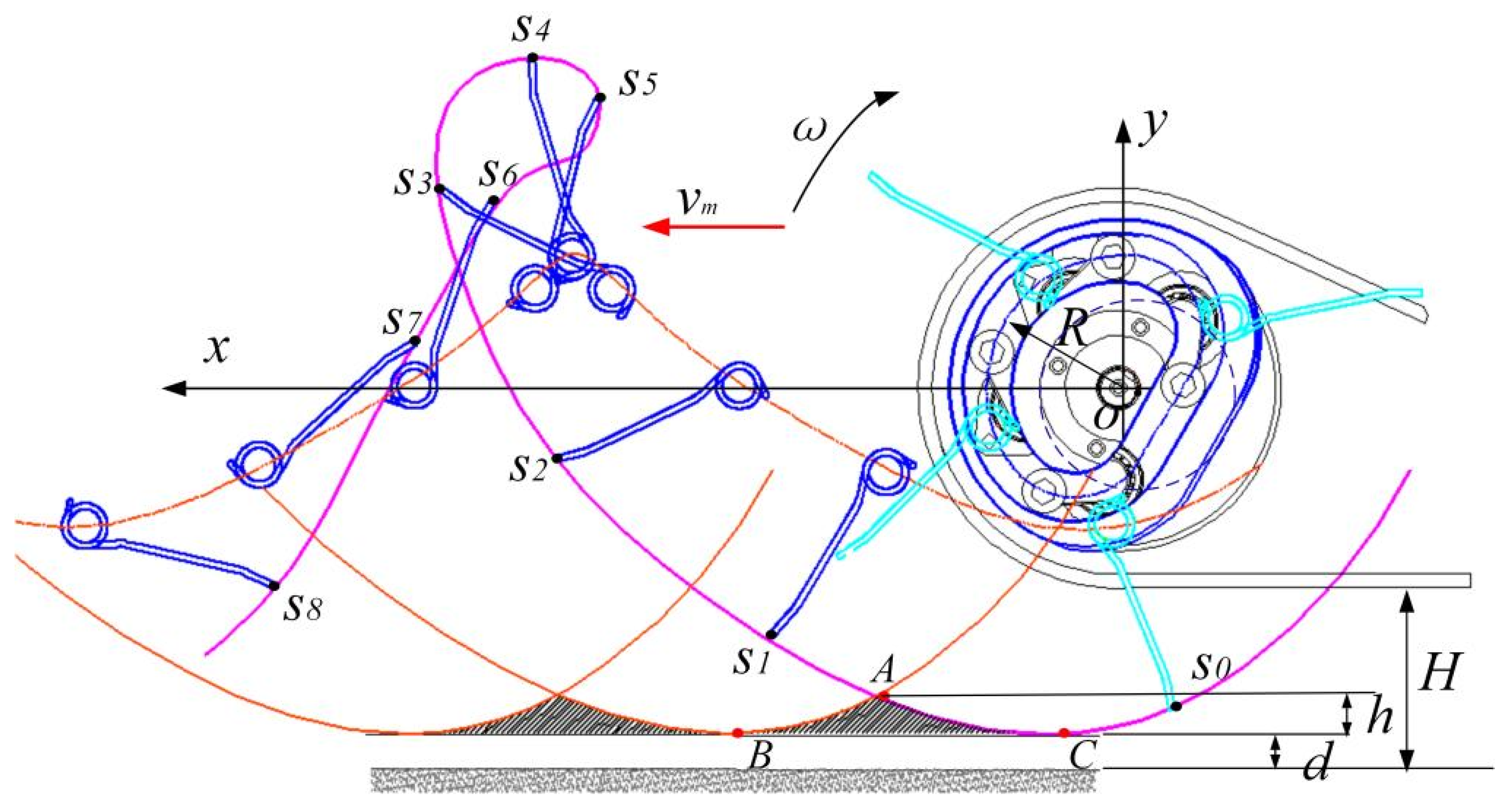
Figure 3 shows the motion track of the picker, where
S0~
S8 is the movement process of the tooth end of a spring tooth at different times, and a green line depicts the movement trajectory. The movement of the spring tooth is a cycloid, and its trajectory equation and velocity equation along the coordinate system in the figure at different times are described as follows:
where
is FV of the baler, with the unit of m/s,
is radius of track groove, with the unit of m,
is rotary angular velocity of track groove, with the unit of rad/s, and
is time, with the unit of s.
In
Figure 3, point A is the intersection point of the motion tracks of the two adjacent rows of spring teeth, and B and C are the lowest points of the two adjacent rows of spring teeth in the motion process. In
Figure 1, ABC’s closed shadow area cannot be covered by the spring teeth in the operating procedure, called the missing picking area. In the operational process of spring teeth, the emergence of the missing picking area is inevitable. The pick-up loss rate (PLR) of the missing picking area is reduced by improving the structure and working parameters. Therefore, to improve the efficiency of straw pickup, the height of the miss picking area should be satisfied:
where
is height of missing picking area, with the unit of m,
is the bottom height of guard plate from the ground, with the unit of m, and
is ground clearance of spring teeth (GCST), with the unit of m.
It can be obtained from Formulas (1) and (2) that the greater the rotation speed, the denser the trajectory curve of the adjacent spring teeth, and the smaller the area of the missing picking area. Appropriately increasing the rotation speed of the picker can reduce the PLR, which is helpful to improve the picking efficiency. However, since the baler on the market that is pulled by a tractor drives the picker to rotate, the tractor’s power output speed is stable. Therefore, the picker rotation speed is fixed. Through the investigation of the baler, it is found that the theoretical rotation speed of the picker is mostly fixed at 287 rpm, and the FV is generally 4~6 km/h.
4. Results and Discussion
4.1. Verification Test
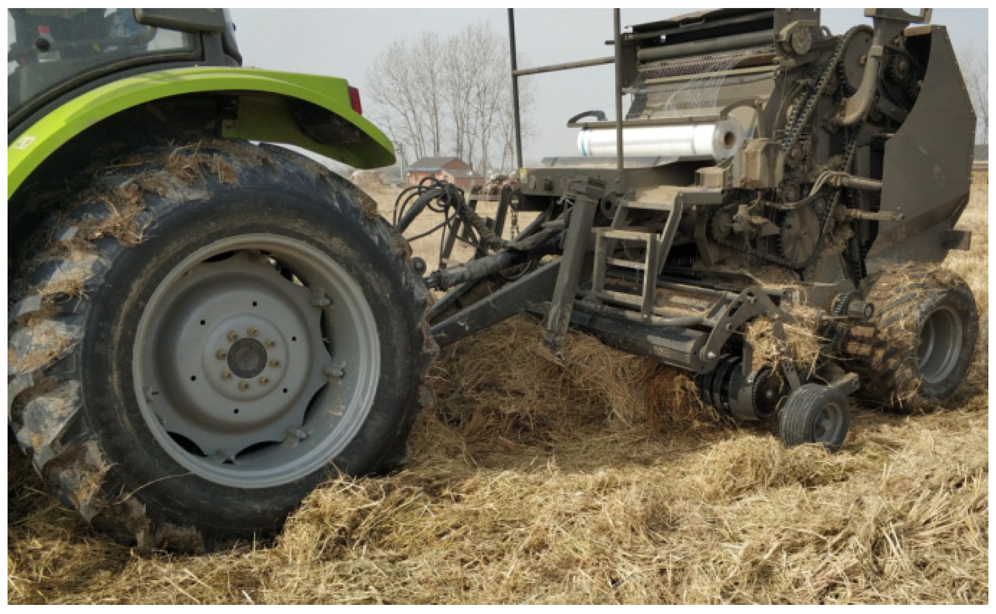
The field validation test is carried out in Datong Town, Tianchang City, Anhui Province. As shown in
Figure 5, the baler model number is 9YY-1250, the tractor is Zoomlion 1204, and the simulated straw mulch amount is about 4.33 kg/m
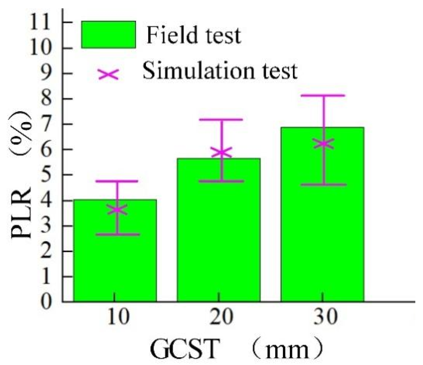
2. During the comparative test, the FV is 5 km/h, and the GCST is 10, 20, and 30 mm, each group of experiments was repeated 3 times. The experimental results are shown in
Figure 6 and
Table 3. Both the simulation and experimental results show that PLR tends to increase with the increase of GCST. The simulation results of PLR are consistent with the experimental results, and the maximum error value is within 2.3. Therefore, the straw picking process can be well simulated by the coupled method.
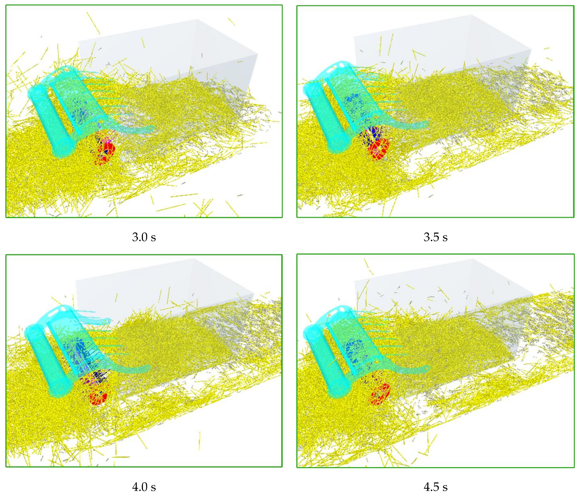
Figure 7 shows the simulation effect of the picker at different times. With the continuous advancement of the picker, the straw on the ground is continuously picked up. The straw in the collection bin gradually increases. Although a small part of the straw is missing, most of the straw is a 70 mm short straw, which is consistent with the field operation effect.
Based on the above results and analysis, it can be easily found that the picker is able to pick up the ground straw successfully and the field operation of the picker can be better simulated by using the proposed coupled simulation method.
4.2. Analysis of the PLR
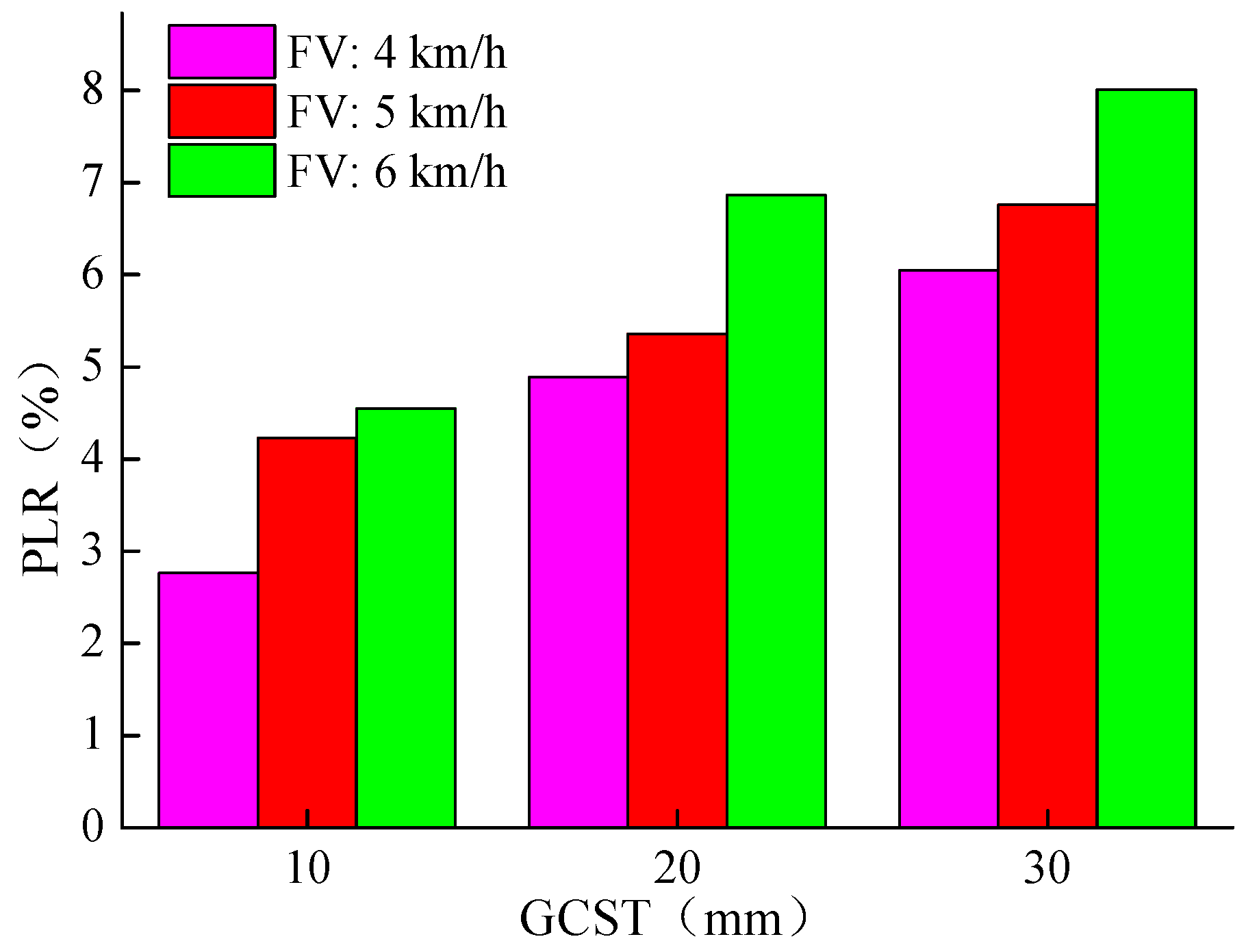
Under the conditions of different FV and GCST, the results of the PLR obtained by the coupling simulation method are shown in
Figure 8. At the FV of 4 km/h, 5 km/h, and 6 km/h, when the GCST increases within the range of 10~30 mm, the PLR increases from 2.76%, 4.89%, 6.05% to 4.55%, 6.86%, 8.01%. Therefore, we can see that the GCST has a significant effect on the PLR. When the GCST is 10 mm, 20 mm, and 30 mm, the PLR increases from 2.76%, 4.23%, 4.55% to 6.05%, 6.75%, 8.01% as the FV increases in the range of 4~6 km/h. Therefore, the FV has a very significant effect on the PLR.
Increasing the FV and the GCST leading to the rising PLR can be explained as follows: When the rotation speed of the picker is constant, the ability of the picker to transport straw backward remains unchanged. With the increase of the FV, some straw will be squeezed and piled up in front of the picker, which will increase the probability of straw spillover and increase the PLR. From the concept of geometry, when the rotation speed of the picker is constant, the ring frequency formed by the rotation of the spring teeth remains unchanged. With the increase of the FV and the GCST, the missing picking area between the adjacent spring teeth gradually increases, which will increase the PLR. Note that the relationship between the above experimental factors and operational performance gives a reference for unmanned tractor-driven baler operation in practical applications.
4.3. Movement Analysis of Straw
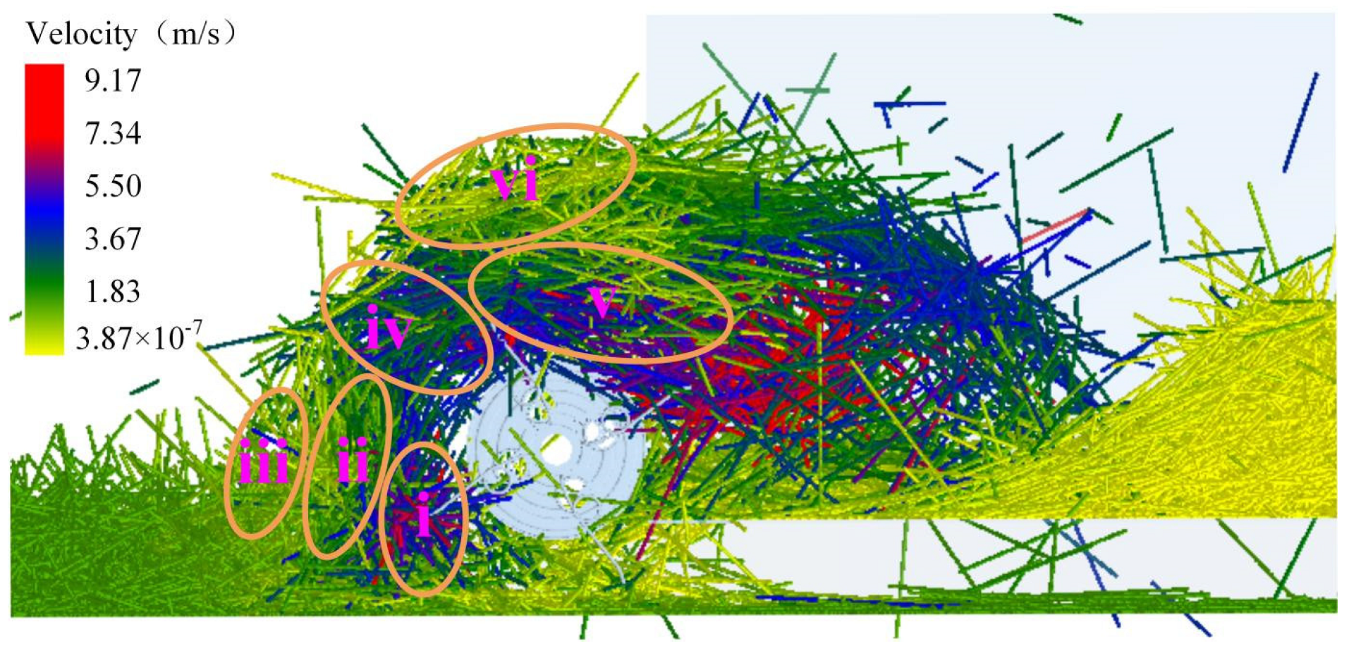
Figure 9 depicts the straw speed change of the picker at a particular time. In order to observe the changes of the straw during the picking process, the straw pressing device is hidden and the side section view is displayed. According to speed change, the straw movement is divided into six regions, where red means high speed and yellow means low speed. Among them, 1 is the picking area, 2 is the towing area, 3 is the extrusion area, 4 is the pushing area, 5 is the throwing area, 6 is the detention area. In the work of the picker and straw pressing device, a straw pile is formed in areas 1, 2, and 3, and a straw feeding area is formed in areas 4, 5, and 6. In the picking work, areas 1, 2, and 3 form a straw pile, and areas 4, 5, and 6 forms a straw feeding area.
The characteristics of different areas are described as follows: (i) For picking area, the spring teeth pick up the straws on the ground, resulting in a significant speed change. (ii) For towing area, in the middle of the straw pile, this part of straw movement mainly comes from the pulling action of straw in the picking area, which cannot directly contact with the spring teeth. (iii) In the extrusion area, located in front of the straw pile, it is mainly the pushing effect between straw, and the speed of this part of the straw is minimal. (iv) in pushing area, an inlet is formed by the picker and straw pressing device. In this area, the straw pile moves upward under the action of spring teeth to create a straw flow, which is transported upward. (v) For the throwing area, the straw flow disperses and continues to move backward, moving to the collection bin under the action of spring teeth. (vi) In the detention area, the straws in this area are formed by straws flow dispersion and gathered together.
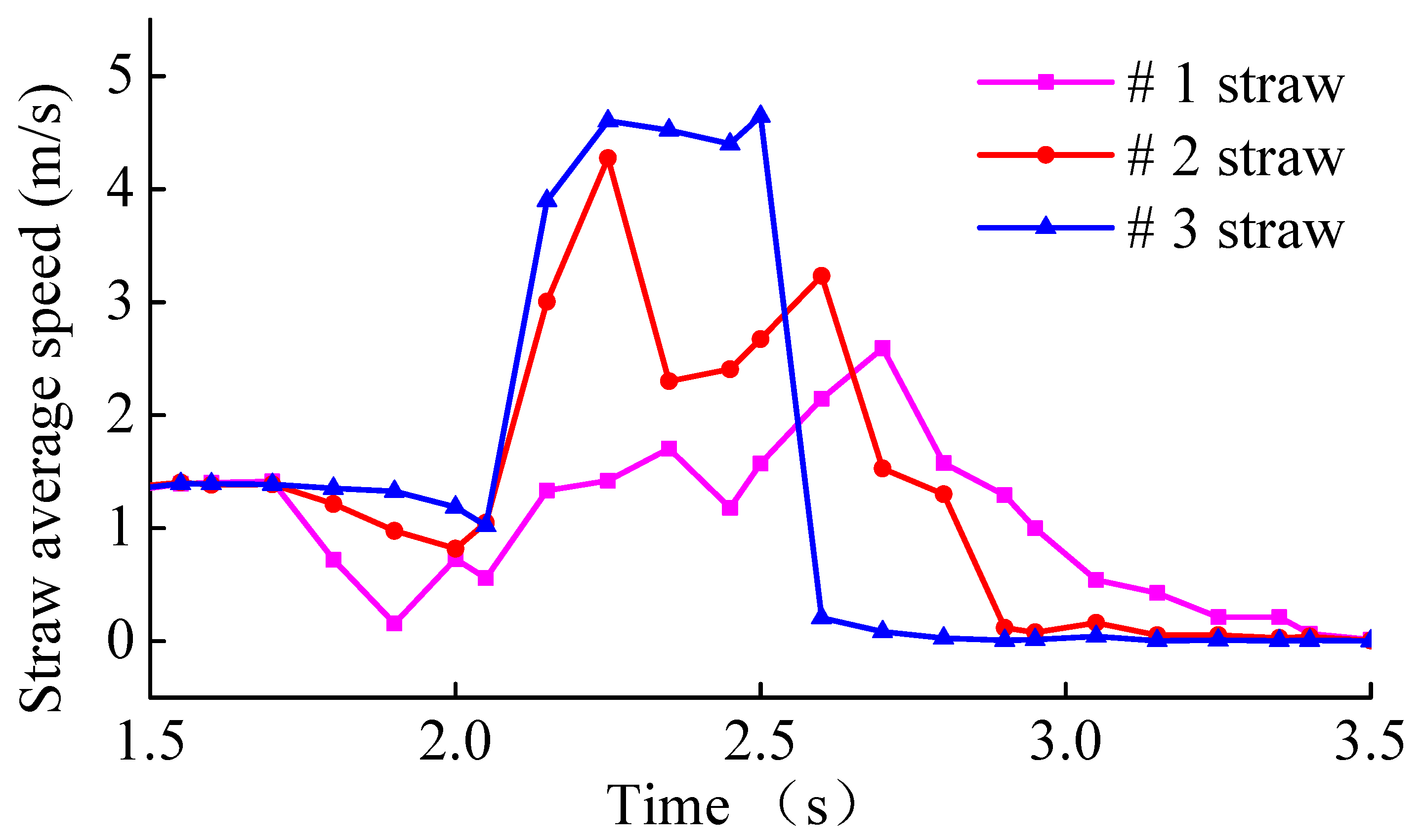
We randomly select three stalks of length 270 mm on the top surface, middle layer and bottom layer of the straw pile, labeled as straw #1, straw #2 and straw #3. The average speed variation of the stalks is observed, as shown in
Figure 10.
From
Figure 10, we can see that the most prolonged duration of speed variation is observed for straws #1 and #2, and the most significant average speed variation exists in straws #2 and #3. This is directly related to the interaction between the straw and the spring teeth. The bottom layer of straw receives the most significant direct force from the spring teeth and moves time shorter. The upper and middle layers of straw have a long residence time and a low movement speed, which is caused by the small force directly from the bullet teeth. We can conclude that the detention area is mainly caused by the accumulation of straw in the upper layer not thrown backward in time, which is the main reason for the blockage.
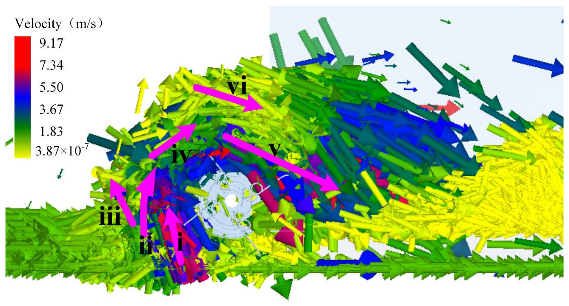
Figure 11 shows the direction and size of the straw movement velocity in each area. The straw in the extrusion area is mainly pushed forward by the picker, resulting in forwarding sliding. The movement of straw in other places primarily revolves around the rotation of spring teeth. It can also be found that the velocity of straw in the detention area is relatively low, which indicates that the straw in this area is mainly dragged by the straw in the throwing area in order to enter the collection bin. The velocity of straw in the pushing area is relatively concentrated, and the straw density is also the largest.
From the above analysis, we can conclude that the blockage of straw mainly occurs in the pushing area. The straw in the detention area is not directly affected by the spring teeth, making it difficult for the straw to be transported to the collection bin quickly. The accumulation of this part of straw will hinder the transportation of straw in the pushing area and increase the probability of straw blockage, especially when the straw mulch amount is significant. Therefore, to avoid blockage during the picking process, the area of the detention area should be reduced to improve the easiness of straw transportation in the pushing area.
In addition, when the straw moves from the ground to the collection bin, both the effect of the action on the spring teeth and a mutual drag effect between the straws will exist. In order to reduce the PLR, the space structure formed by the straw pressing device and the picker can be improved, and the structure and size of different areas can be optimized. Not only can the efficiency of the spring teeth be improved, but also the drag effect between the straws can be increased, resulting in the more efficient straw pile moving to the straw flow.
4.4. The AF between the Roller and the Track Groove
The impact between the roller and the track groove will affect the work efficiency and service life of the picker [
15,
18]. The traditional method is difficult to predict the AF. Therefore, the AF change between “roller 1” and track groove in a rotation period of 3.0~3.25 s is observed in this study.
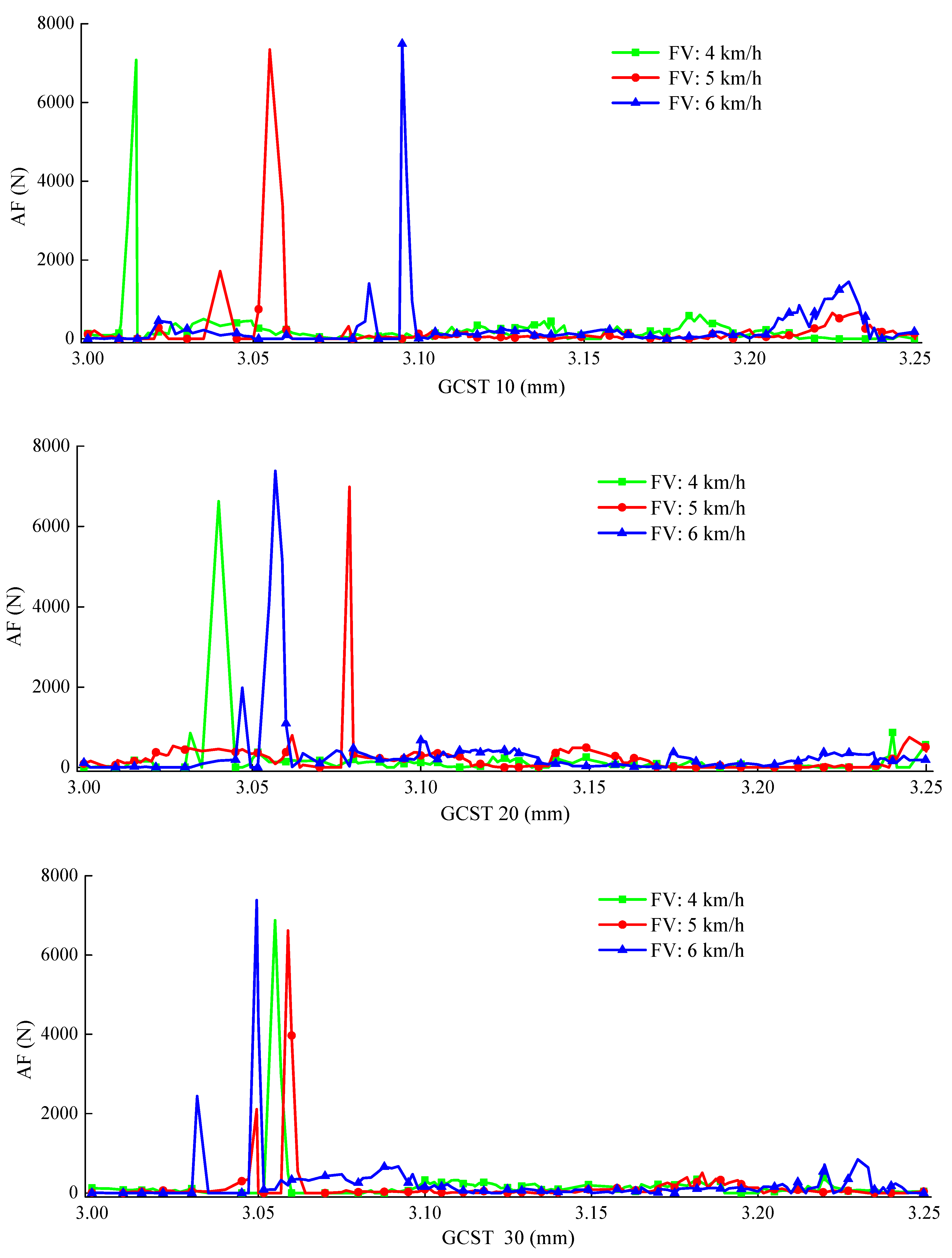
Under the condition that the GCST is 10, 20, and 30 mm, the AF at different FV is shown in
Figure 12. We can find that the AF changes significantly in a movement cycle, which is mainly reflected in the peaks and valleys in a small area. Under different conditions, the corresponding AF of the peak is about 6500~7500 N. When the GCST is 10, 20, 30 mm, the peak value shows a gradually increasing trend as the FV increases. Excluding the peak value, the AF change is relatively stable. In some areas, there is also a tendency to grow with the FV increases. However, most of them are in the range of less than 500 N, which has less impact and wear on the track groove.
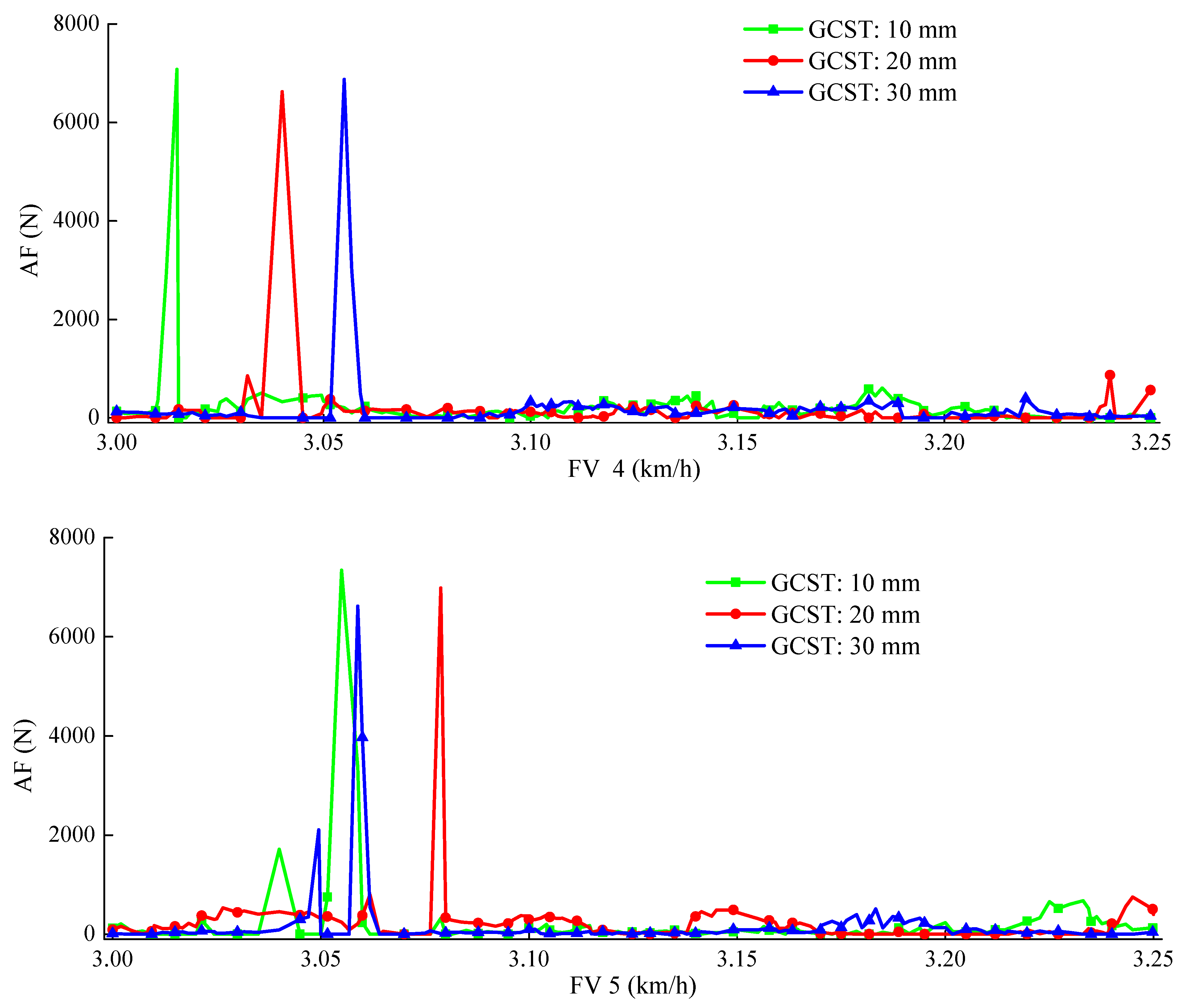
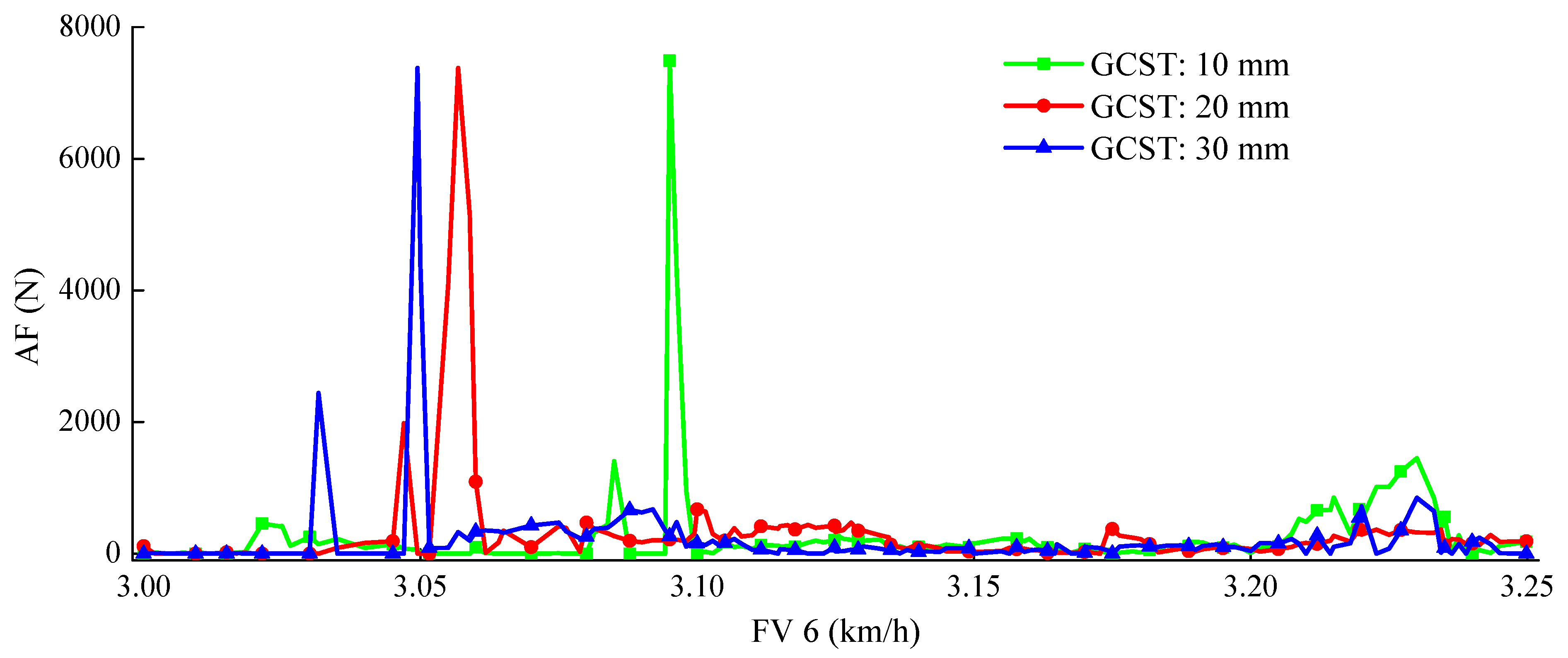
Under the conditions of 4, 5, and 6 km/h, the changes in the AF caused by the GCST are shown in
Figure 13. It can be seen that there is a small part of peaks and valleys in a motion cycle and the maximum AF is 6500~7500 N. The peak value tends to decrease as the GCST increases. Except for the peak part, most of the AF is more diminutive than 500 N, and no apparent change in these AF under different GCST occurs.
According to the analysis of the AF between the roller and the track groove, the AF is relatively gentle in most of the process, and the difference is not apparent under different working conditions. However, there is a more significant peak during a movement cycle.
As illustrated in the above analysis, the interaction between the straw and the spring teeth has a negligible effect on the AF. The structure of the track groove is unreasonable in a specific region, which leads to a sudden change of AF when the roller moves to this region. This phenomenon is harmful to the picker, which not only increases the vibration and intensifies the wear of the track groove, but also results in lower operating efficiency and shorter service life. Therefore, it is necessary to avoid this phenomenon during the operation of the picker.


 and
and 


