1. Introduction
In designing railway turnouts, the plane alignment of turnouts is first identified. In this process, the plane alignment usually has an accurate design when the stock and switch rails are in close contact, but the design is often simplified when the rails are separated [
1,
2,
3,
4]. Shen et al. [
5,
6] studied aspects of this, such as turnout plane alignment, structure, and speed-up dimensions. Liu et al. [
7] combined recently developed mature technologies and designed a new No. 12 single turnout with 60-kg/m rails, with a speed in a straight direction of 200 km/h. It enhanced the plane alignment and dimensions, optimized the structure, strengthened the resilience and stability of components, and ensured interchangeability with existing speed-up turnouts. He et al. [
8] used system integration design methods to establish a body of design theories for 250-km/h passenger-dedicated lines. They covered turnout dynamic strength, seamless turnout design, conversion calculations, and track stiffness design, which helped optimize the turnout plane alignment. They also developed a new fastener system and electrical and mechanical structures at the first traction point of nose rails and realized a reasonable setting and homogenization of track stiffness at turnout crossings. Gao et al. [
9] used the longitudinal-transverse coupling model to conduct in-depth research on the ballastless and jointless No. 42 turnouts to identify the longitudinal force and deformation, transverse deformation of turnout rails, the allowable temperature variation range of jointless turnouts, and the limiter’s laying and maintenance methods. Cao et al. [
10,
11] leveraged a plane parameter method to derive calculation formulas of various plane alignments, proposed a design process of the turnout plane alignment, and compared the application range and advantages and disadvantages of various alignments using actual calculation examples. Yang et al. [
12] optimized the design of No. 9 single turnouts with 60-kg/m rails in subways. They adopted a straight-curve combined plane alignment, sliced the stock rail, and thickened the switch rail to increase the wear and impact resistance of switch rails. Guo et al. [
13] elaborated on the design parameters and plane alignment of No. 62 turnouts, with a side allowable speed of 220 km/h, analyzed the switch, frog, fastener system, ballastless track foundation, switching system structure, and calculated principal component parameters. Furthermore, wheel-rail dynamics was used to analyze the safety and stability of Electric Multiple Units passing through No. 62 turnouts. Yang et al. [
14] proposed the design principles and technical indicators applicable to No. 18 turnouts with 40 t axle-load rails. The simulation analysis signified suitable dynamic performance of the plane alignment and fairly good wear resistance of the curved switch rails. To meet the construction needs of the Moscow–Kazan high-speed railway, Wang et al. [
15] designed high-speed and wide-gauge turnouts suitable for 400 km/h. The design was based on dynamic analysis theory of high-speed turnouts and mostly covered plane alignment, profile processing of straight stock rails, vertically elevated structures of wing rails, and the stiffness of even and elastic turnouts. Luo et al. [
16] researched the 160-km/h turnout system of urban rail transit lines, focusing on plane alignment, structure and construction, track foundations, and engineering-electrical interfaces. Wu [
17] studied the No. 10 single turnout design with 1000-mm gauge and 50-kg/m rails and optimized and determined the plane dimensions of turnouts. Wu focused on the structure and engineering of the switch, frog, and track foundations and evaluated various parameters, such as the radius of the guide curve, the gauge widening, and the interval between various turnout parts.
Currently, the most commonly used method employs the following procedure: after designing the plane alignment of the switch rail in close contact with the stock rail is determined, the movable section of the switch rail is rotated with the fixed end or heel of the switch rail as the center of the circle until the displacement of the switch rail at the first traction point position is consistent with the designed stroke. The plane alignment, therefore, is considered as the plane alignment of the switch rail when not in a closed position. The plane alignment of the switch rail obtained in this way often remarkably deviates from the actual situation.
However, the plane alignment of the switch rail separated from the stock rail is important. For turnouts with internal locking, it is necessary to calculate and determine the lengths of the tie and connecting rods according to the plane alignment of the switch rail when separated from the stock rail. For speed-up and high-speed turnouts, the position of the components, such as the anti-jump iron block, is determined by the plane alignment of the switch rail when it is separated from the stock rail. In addition, the plane alignment determines the minimum width of the flangeway between the switch and stock rails, which directly impacts the design of the traction stroke. Therefore, the plane alignment of the switch rail in the separated state is measured as accurately as possible during the design. This simplified approach has major drawbacks: it can cause considerable deviations in the design of relevant components and the design of the traction stroke, resulting in a significant negative impact on the manufacturing, laying, and use of turnouts.
Currently, China’s state-owned railways comprise about 22,000 sets of No.9 turnouts with 60-kg/m rails, representing a huge volume of railway laying. The No. 9 turnout is a 1/9 turnout or a turnout with a crossing angle of arctan 1/9. The main product drawing number is CZ577, which was designed in 2002, and it is applicable to railway lines with a speed of ≤120 km/h and a transverse passing speed of 35 km/h [
18,
19,
20,
21]. Based on the on-site feedback and statistics, No. 9 turnouts of 60-kg/m rails are mainly used in the mainline, arrival, and departure line turnouts of the passenger and freight line I railways, arrival and departure line turnouts of heavy-haul railways, and other station line turnouts. There are prominent problems associated with the process, including poor maintenance of turnout geometric dimensions, short service life of components, and heavy maintenance workload [
22,
23,
24,
25]. There is an urgent need to boost the performance of No. 9 turnouts with 60-kg/m rails for railway engineering. Therefore, a study was organized by the China State Railway Group to improve the design of the main No. 9 turnouts with 60-kg/m rails [
26,
27]. Firstly, the dimensions of the new turnout were adopted consistent with those of previous turnouts to ensure interchangeability. Secondly, to address onsite issues and ensure safe dynamics of trains passing through the turnout, a series of new technologies was used in the new switch, such as straight-curve combined switch-rail technology to improve the wear resistance of the switch rail, the embedded iron seat fastener system to improve the switch’s stability, and a new alloy-steel combined frog to increase the service life of the frog.
Based on optimization requirements and considering the shortcomings of existing design methods for turnout switching, herein, we revamped the switching design of the No. 9 single turnout with 60-kg/m rails, proposed a simulation calculation method to identify the plane alignment of the turnout switch rail in the separated state, and optimized key design parameters, including the traction point stroke and the length of the tie and connecting rods. Finally, the rationality of the design method and parameter scheme was verified through actual switching tests.
2. Calculation Method for the Plane Alignment of Turnout Switch Rails Separated from Stock Rails
The new No. 9 single turnout of 60-kg/m rails has the CZ577 turnout dimensions, with the total, front, and rear lengths of 29,569, 13,839 and 15,730 mm, respectively. Considering the simplification-incurred change in the side rail gauge of turnout, the diverging rail takes R195-m single circular curve, the turnout Q value is 2600 mm, and the gauge is widened to 1445 mm at the toe of the switch rail. The straight rail ends at the railhead slicing the starting point of the switch, and the end has a structural gauge widening by the curved stock rail deflection. The backtrack gauge is 1435 mm, the lateral track gauge is maintained at 1445 mm and shifted back to 1435 mm before the turnout guard rail. The separation value of the diverging rail is 30 mm, the length of the front straight section of the curved switch rail is 3499 mm, and the width at the semitangent point is 54.9 mm.
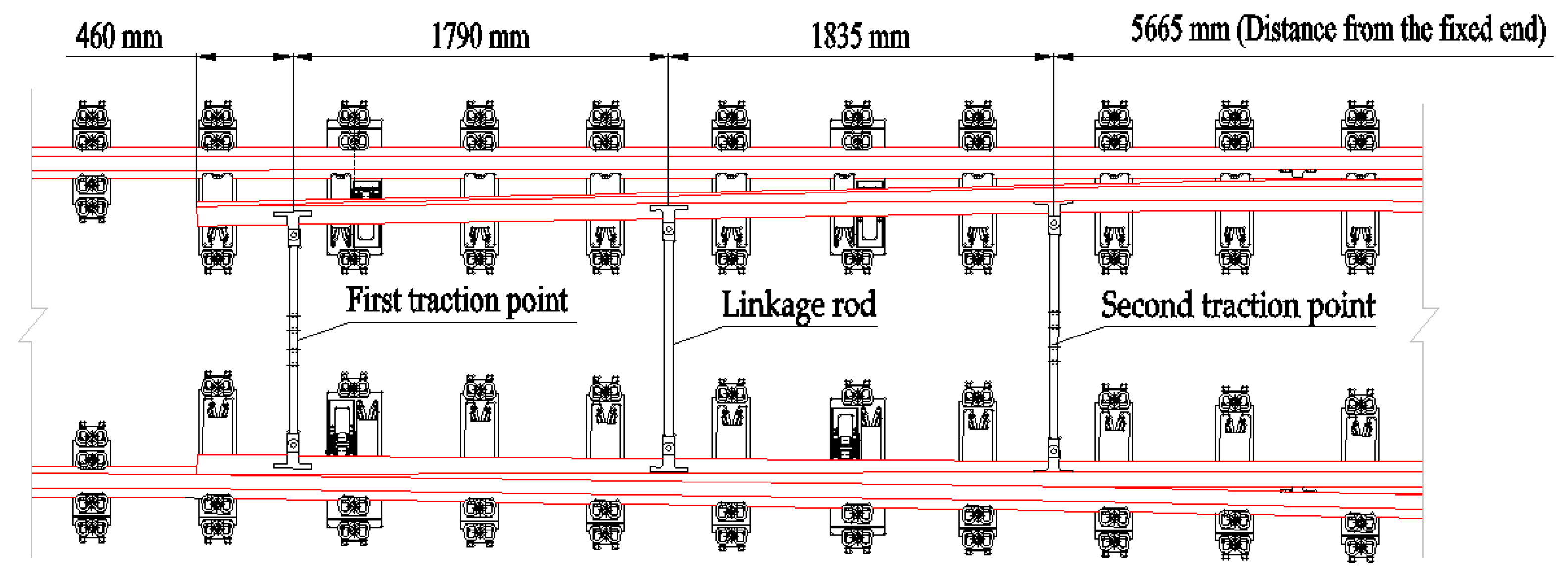
The switching adopts joint internal locking. The switch is designed with 2 traction points; the first traction point is 460 mm from the toe of the switch rail, and the second is 3625 mm from the first traction point and 5665 mm from the fixed end of the switch rail. The internal locking connecting rod is installed 1790 mm from the first traction point (
Figure 1).
Existing CZ577 turnouts have been optimized in aspects such as the length of the switch rail and position of the traction point, and the switch rail adopts a more flexible 60AT2 steel rail. Therefore, existing stroke designs cannot meet the requirements regarding minimum flangeway width and other aspects, the stroke design at traction points is no longer adaptable. To ensure that the minimum flangeway width meets the requirement and minimizes the switching force, it is necessary to upgrade the design of the traction point stroke and length of the correspondent tie and connecting rods of internal locking.
The first step is to obtain the plane alignment of the switch rail that is not close to the stock rail by establishing a turnout switching calculation model based on finite element theory. It can serve as a rationale and means for the scientific design of the above parameters.
A solid unit is used to simulate the switch rail, with a material density of 7850 kg/m
3, modulus of elasticity of 2.1 × 10
11 Pa, and Poisson’s ratio of 0.3 [
28,
29,
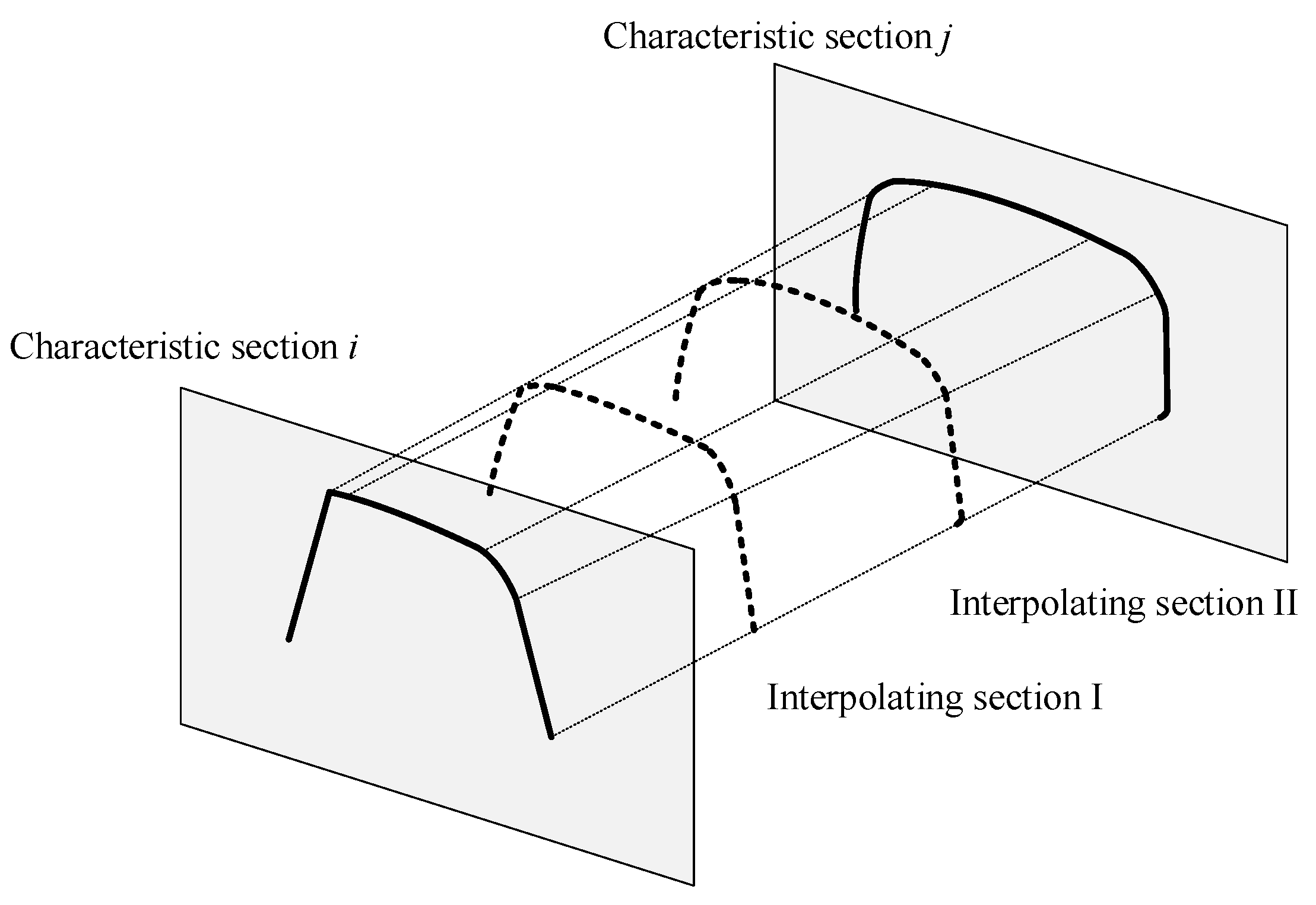
30]. The influence of the variable cross-section of the switch rail is considered, and each characteristic section of the switch rail is imported from the tip of the switch rail to the full cross-section, including the 0-mm, 5-mm, 20-mm, 50-mm and full sections of the top width of the switch rail, and the transition between the characteristic sections employs linear interpolation (
Figure 2).
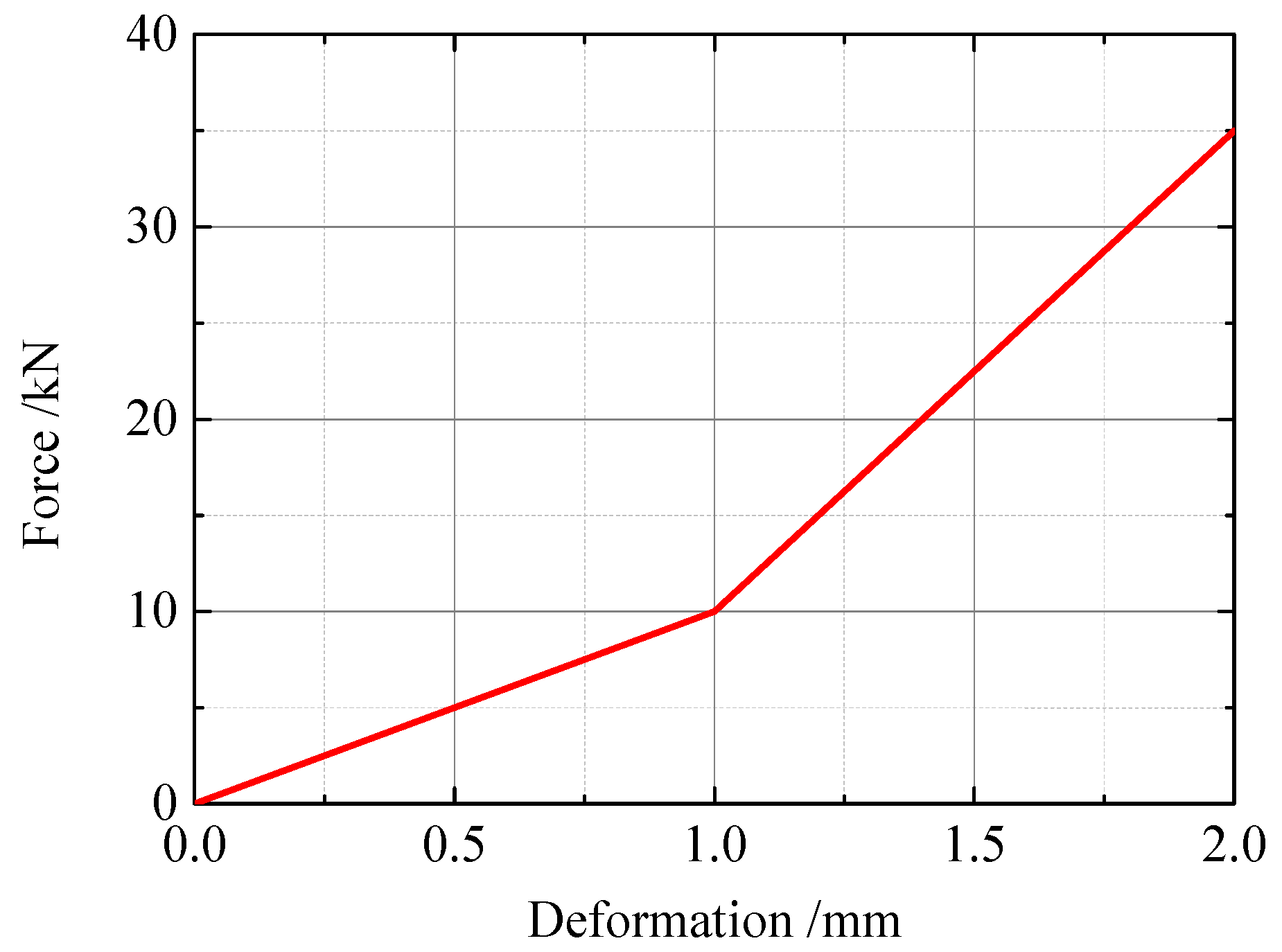
The heel of the switch rail is set as a fixed end support, and the influence of friction during the wrenching of the switch rail is considered. The spring unit is used to simulate the fastener system at the rear end of the switch rail. The lateral stiffness of the fastener system takes the values shown in
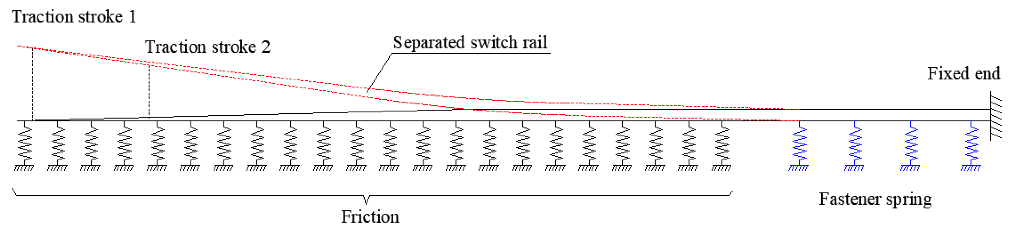
Figure 3. The frictional force adopts a uniform load. The assumed weight of the switch rail is 70 kg/m, and the friction coefficient is 0.25, so the applied frictional force is 175 N/m. When the switch rail is separated, transverse displacement load equal to the corresponding traction stroke is applied at each traction point. The switching simulation model is shown in
Figure 4.
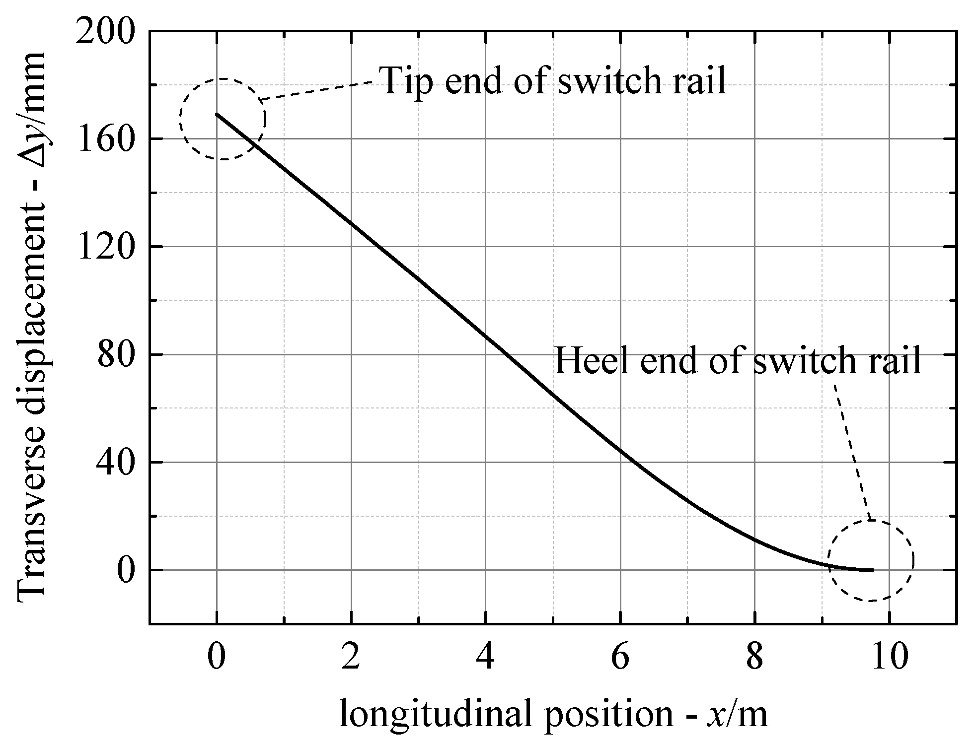
Through the above calculation, the transverse displacement distribution curve of the switch rail separated from the stock rail can be obtained (
Figure 5), where
is the coordinate of the longitudinal position along the switch rail, and
is the transverse displacement of the switch rail at different positions. To facilitate subsequent analysis, the data are discretized. The switch rail is divided into
segments along the longitudinal direction, resulting in
nodes. The position coordinates of each node are
, and the corresponding transverse displacement is
, respectively.
Based on the design scheme, the plane alignment of the switch rail very close to the stock rail is obtained. The same discretization method is employed on the switch rail to obtain the longitudinal position coordinates of
and the corresponding transverse position coordinates
. The transverse position coordinates
of the switch rail in contact with the stock rail and the displacement distance
after the separation from the stock rail are calculated by adding data on each discrete node
to obtain the transverse position coordinates
of the switch rail when separated from the stock rail.
Based on the position coordinates of each discrete node when the switch and stock rails are separated, the plane alignment of the switch rail under the separated state can be obtained by sample curve fitting.
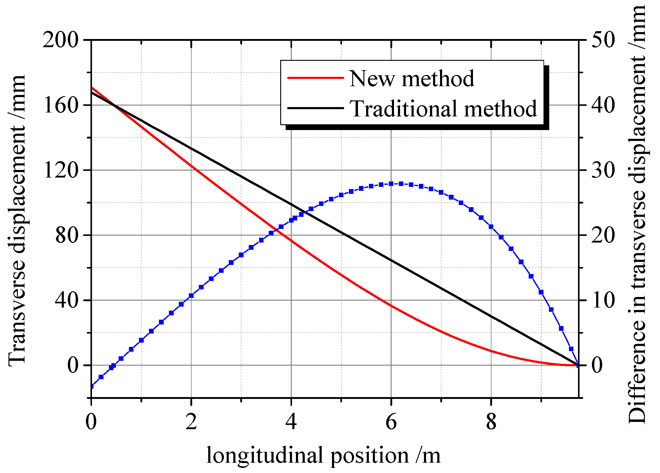
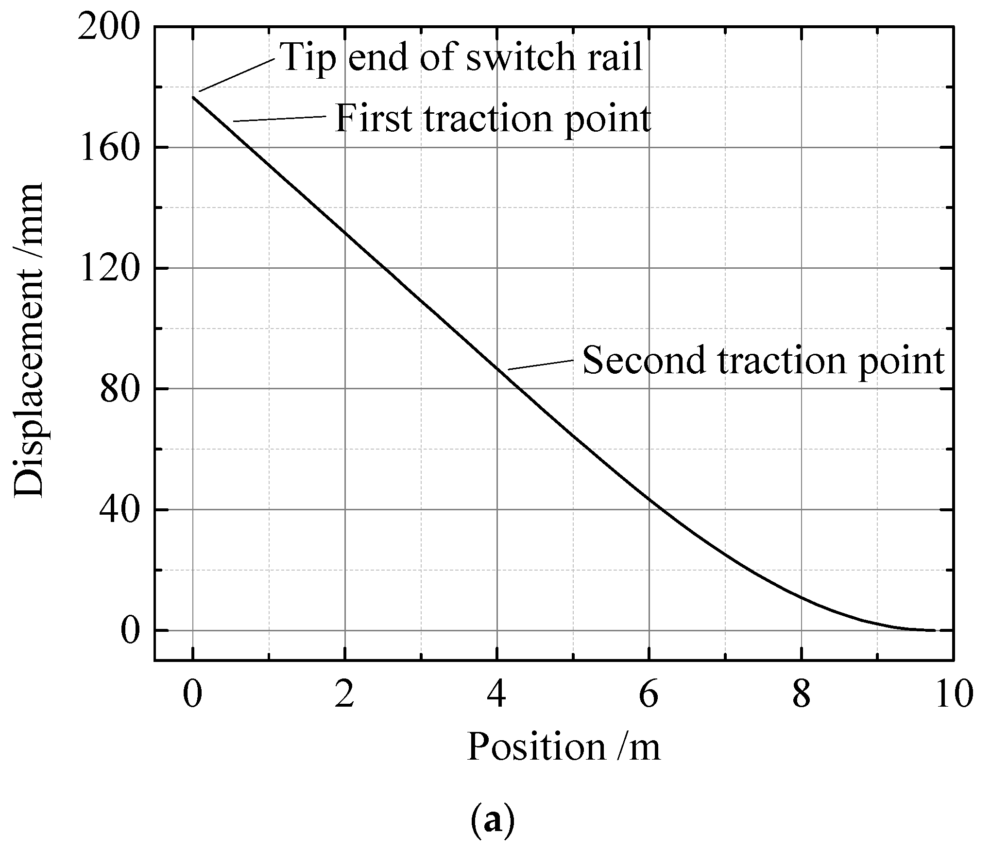
The stroke of the first traction point is preset to 160 mm, and that of the second traction point is 75 mm. Under this condition, the difference between the plane alignment of the switch rail under the separated state obtained using the proposed and traditional methods is shown in
Figure 6. The transverse displacement of the switch rail under the separated state, obtained using the traditional method, is higher than that obtained using the proposed method; it is small only before the first traction point. The maximum deviation reaches 27.9 mm, which is large enough to jeopardize the accuracy of the design of the parameters related to rail switching. In addition, the actual minimum flangeway width after assembly is less than 65 mm of the width of the flangeway is set at 65 mm during the design because the transverse displacement of the switch rail under the separated state obtained using the traditional method is larger than that in the actual situation. This adversely affects the safety of trains passing the turnout. The proposed method determines the plane alignment under the separated state based on the actual force imposed on the switch rail, which is consistent with the actual situation and more dependable.
3. Optimized Design of the Traction Point Stroke
Based on the developed turnout switching calculation model, the traction point stroke of the new-type No. 9 single turnout with 60-kg/m rails is optimized.
Firstly, considering the general design code for railway turnouts, the first traction point stroke is fixed to 160 mm [
31,
32,
33]. The new No. 9 single turnout with 60-kg/m rails has 2 traction points, and the second traction point stroke needs to be properly designed. The design of the traction point stroke must meet the requirements of the minimum flangeway in the first place, i.e., the distance between the non-working edge of the switch rail and the working edge of the stock rail must be greater or equal to 65 mm in the switch rail when separated from the stock rail [
34,
35]. As the new No.9 single turnout with 60-kg/m rails slices the stock rail and thickens the switch rail to improve the wear resistance of the curved switch rail, and the working side of the straight stock rail is planned by 5 mm, so the minimum flangeway width must be greater than or equal to 70 mm.
The numerical test conditions are listed in
Table 1.
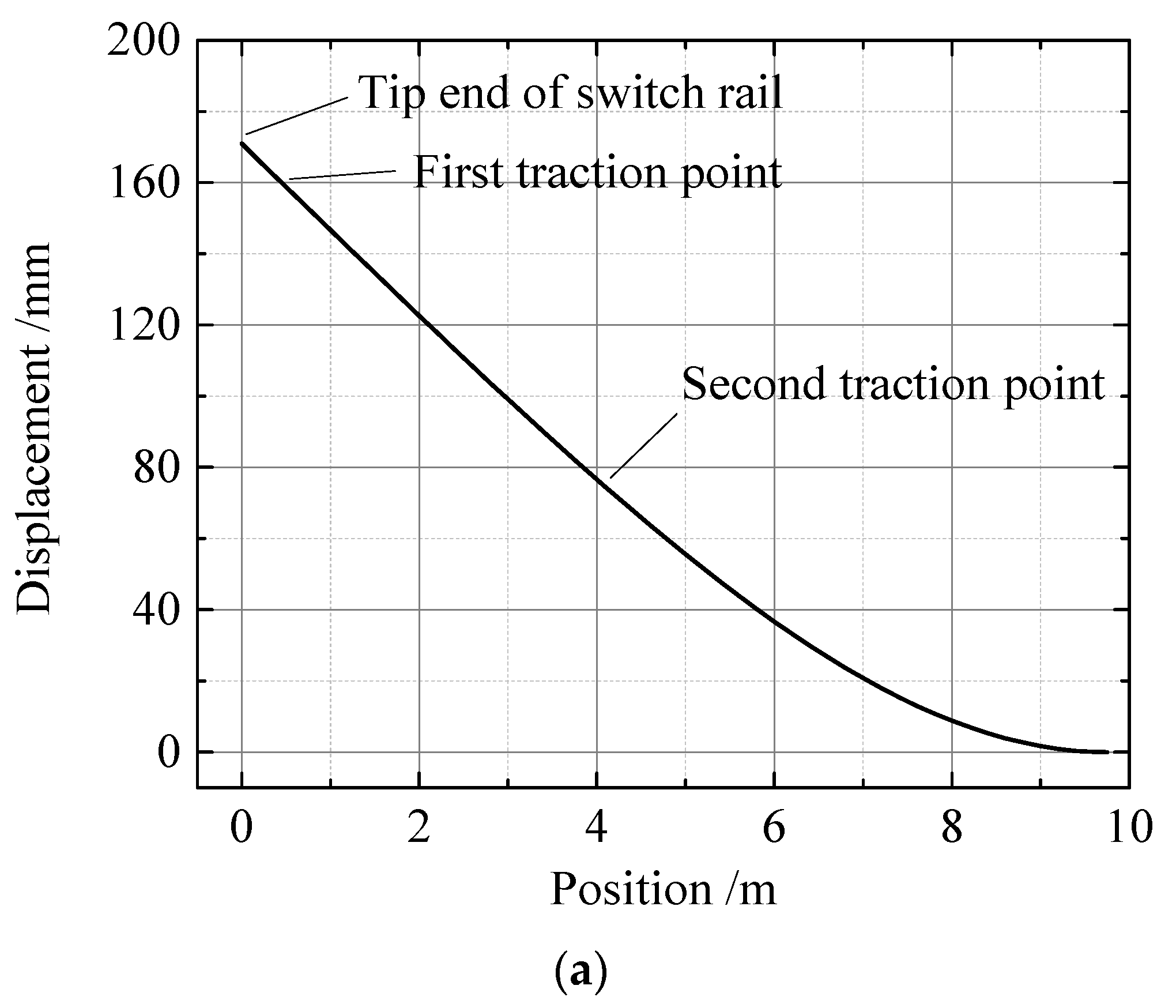
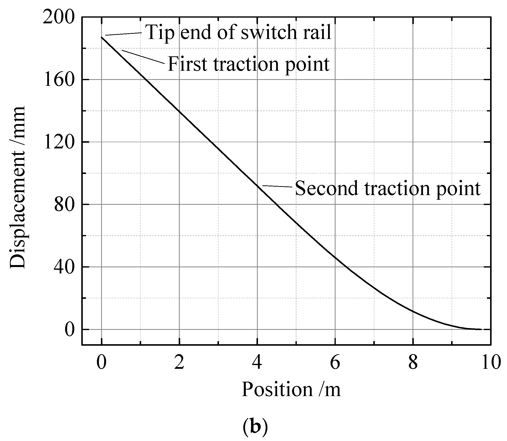
The transverse displacement curves of the switch rail when separated from the stock rail under different calculated working conditions are shown in
Figure 7, and the results of the minimum flangeway calculation are listed in
Table 2.
When designing the traction stroke considering the No. 9 single turnout of 60-kg/m rails, the minimum flangeway width is 65.2 mm, which does not meet the requirements and would affect the safe passage of trains through the turnout. With an increase in the stroke of the second traction point, the minimum flangeway width gradually increases. When the stroke of the second traction point reaches 80 mm, the minimum flangeway is 70.0 mm, a desired width, but with no safety margin, which does not meet the standard considering the influence of manufacturing tolerance. When the second traction point travels up to 85 and 90 mm, the minimum flangeway width becomes 74.8 and 79.6 mm, respectively, with adequate safety margins.
The design of the traction point stroke, besides minimizing the traction force at the first and second traction points, should reduce the working power of the switch device. In addition, the deformation of the switch rail should be coordinated to avoid uneven deformation. The additional numerical test conditions are set up as shown in
Table 3.
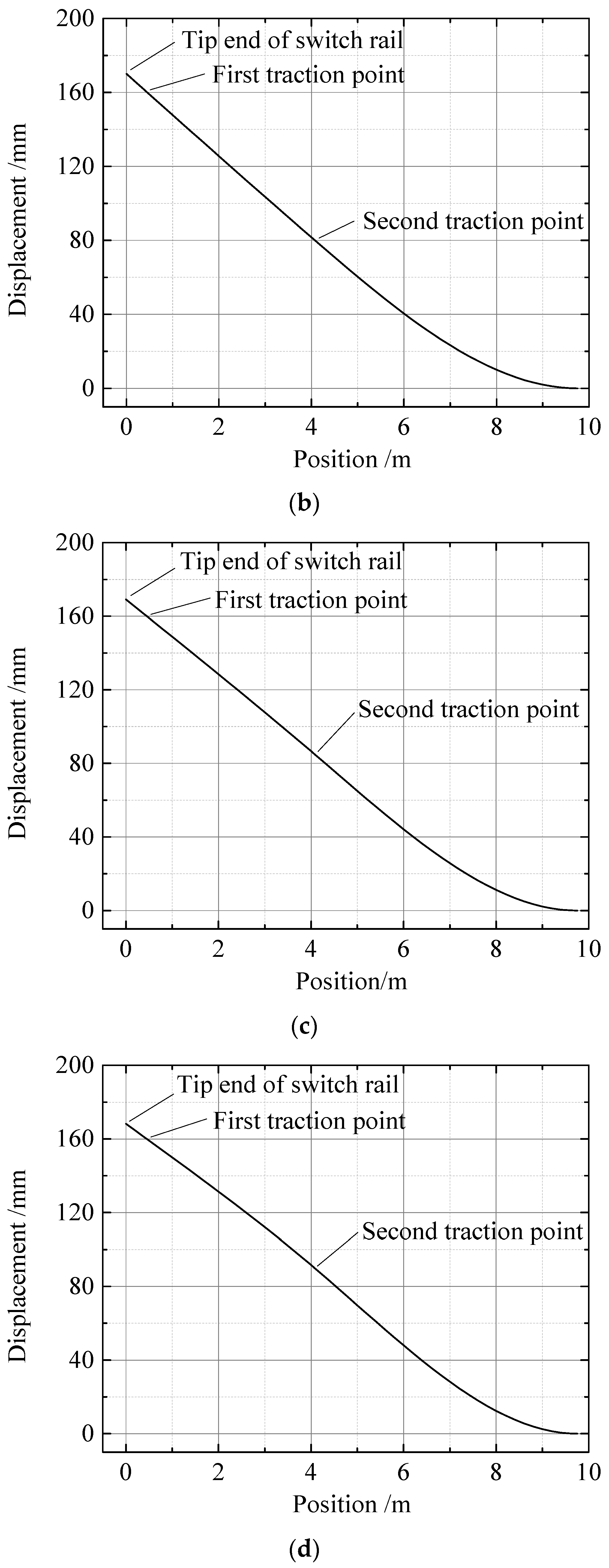
The transverse displacement curves of the switch rail separated from the stock rail under different working conditions are shown in
Figure 8, and the calculation results of the free stroke of the switch at the first traction point are listed in
Table 4.
When the first traction point is released and the second traction point stroke is 85 mm, the free stroke of the first traction point is 166 mm. Therefore, when 160 mm of the stroke is applied to the first traction point, the switch rail is deformed in a more coordinated way, and the strokes of the first and second traction points match better. When the first traction point is released and the second traction point stroke is increased to 90 mm, the traction force of the second traction point would be increased, and the free stroke of the first traction point reaches 176 mm. Then, if 160 mm stroke is applied at the first traction point, the switch rail deformation becomes uneven, and the first traction point produces a reverse obstruction effect, further increasing the traction force of the second traction point.
In summary, the simulation shows that when the stroke of the second traction point is 85 mm, the requirements of the minimum flangeway can be satisfied while leaving a safety margin. In this case, the deformation of the switch rail can be more even, the strokes of the first and second traction points match better, and the traction power is reduced to the minimum. Therefore, for the new No. 9 single turnout of 60-kg/m rail, the strokes of the first and second traction points are designed to be 160 and 85 mm, respectively.
4. Switching Test Verification
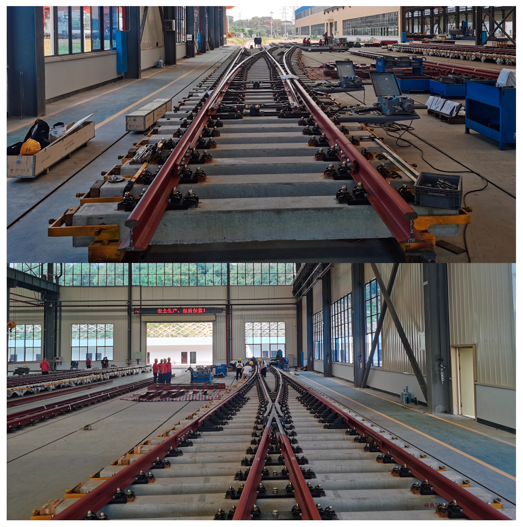
Based on the proposed design, the new No. 9 single turnout of 60-kg/m rail was constructed and laid (
Figure 9).
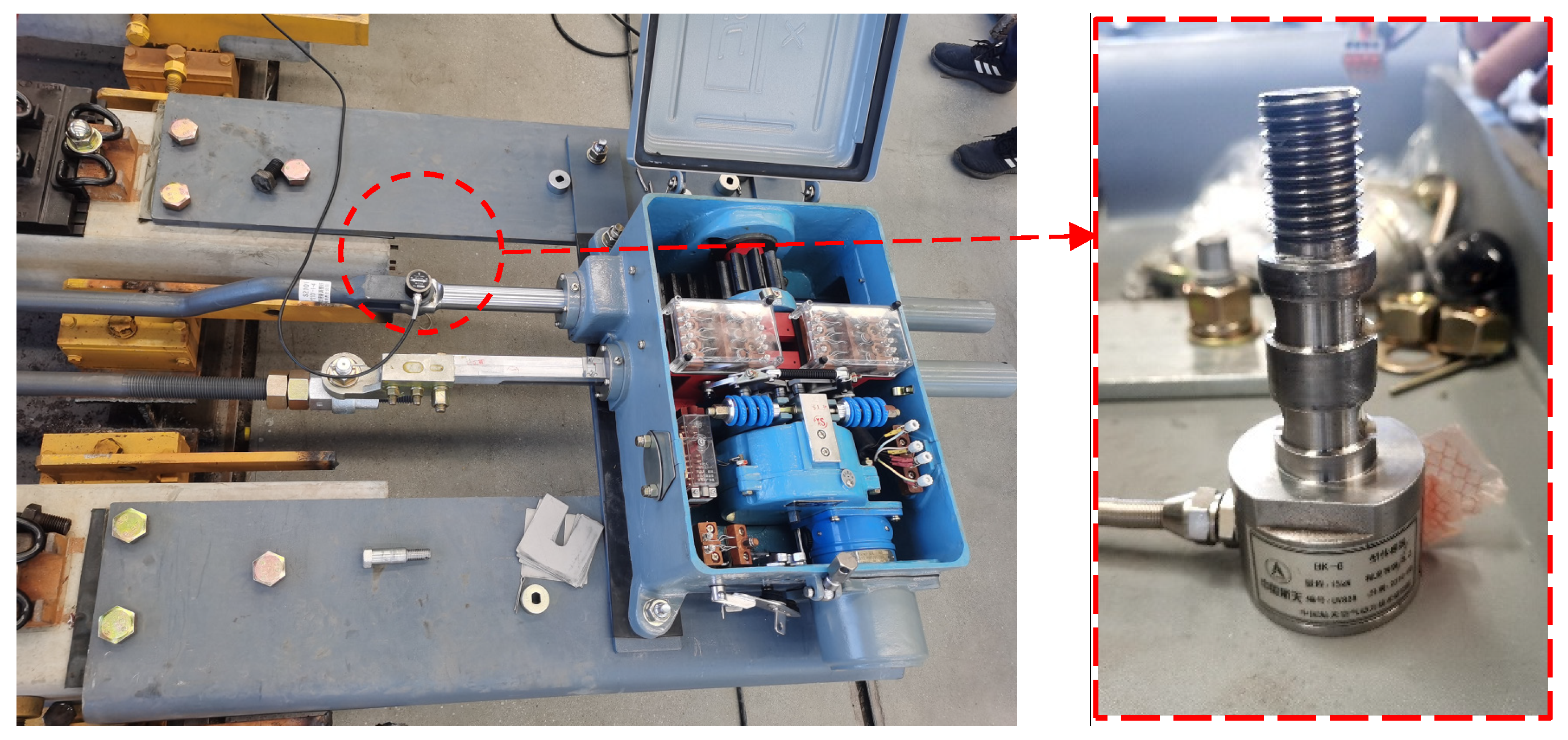
A ZD6 electric switch and supporting locking devices were installed and conditioned at two traction points. After acceptance, a switching test was conducted. First, multiple cycles of pre-switching were conducted, and then, measurements and data reading were started.
Switching force was measured using a pin-type load cell (
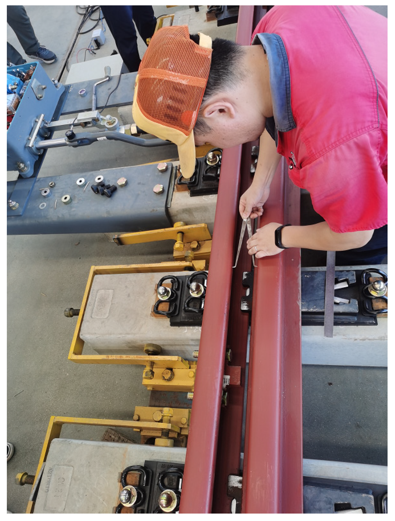
Figure 10). The measured signal was converted to data using a dynamic signal test analyzer and the data were analyzed and stored using DHDAS software. After measuring the switching force, a special caliper was used to gauge the minimum flangeway (
Figure 11).
After the pre-switching, the switch was flipped back and forth three times. The switching force at different traction points during each flip and the test result of the corresponding minimum flangeway after the flip are shown in
Table 5 and
Table 6, respectively.
The average switching force was 1400 and 2100 N at the first and second traction points, respectively, when pulled from the forward to the reverse position. When pulled from the reverse to the forward position, the force was 1133 and 1933 N at the first and second traction points, respectively.
The average value of the minimum flangeway in the straight switch rail when separated from the stock rail was 77.8 mm (because the side stock gauge was widened by 10 mm, so it must be 75 mm or higher), with a 3.8-mm safety margin. The average value of the minimum flangeway in the curved switch rail separated from the stock rail was 74.9 mm (because the straight stock rail was planned by 5 mm, so it must be 70 mm or higher), with a 4.9-mm safety margin.
Based on the field test data, the switching force of the existing main-type No. 9 turnouts with 60-kg/m rail is 2000–3000 N. In general, the new No. 9 single turnout with 60-kg/m rail exhibits a smaller switching force; thus, it is superior to existing main-type No. 9 turnouts. Besides, its minimum flangeway width meets the requirements and allows for a certain safety margin. The test data prove the effectiveness of the proposed switching design method.
5. Conclusions
In this study, based on the optimization requirements of No. 9 single turnout of 60-kg/m rail, we improved the switching design of No. 9 single turnout of 60-kg/m rail by removing the shortcomings of existing turnout switching design methods. Based on finite element theory, a turnout switching simulation method was established, which can determine the plane alignment of the switch rail based on the actual force acting upon it in the case where the switch and stock rails are separated. Hence, the obtained plane alignment is consistent with the actual situation and reliable. Based on this, we investigated the determination of reasonable stroke values of the traction point. Further, we analyzed the minimum flangeway width and the relationship between the stroke at the first and second traction points under different stroke conditions by numerical simulations. We further propose an optimization scheme or strokes of 160 and 85 mm for the first and second traction points, respectively.
Based on the proposed scheme, the production and laying of the new No. 9 single turnout of 60-kg/m rail, as well as the switching test, were conducted. The switching force of the new-type No. 9 turnout at the first and second traction points was approximately 1200 and 2000 N, respectively, which are better than those of existing main-type No. 9 turnouts of 60-kg/m rails. The minimum flangeway also satisfies the requirements and has a safety margin of 3–5 mm. The results prove the effectiveness of the proposed switching design method and parameter optimization scheme.
In further studies, the new-type No. 9 single turnout of 60 kg/m rail, which is trial-produced, shall be laid on actual operating lines. In addition, long-term tracking and tests on the usage and switching status of the turnout will be conducted, and the design method and scheme will be further verified. In addition, the switch rail deforms as the temperature changes. However, such deformation will be insignificant for No. 9 turnouts because the overall turnout and switch-rail lengths are relatively short. Therefore, temperature variance was not factored into the switching design; instead, the analysis was performed under the middle value of onsite temperature ranges. In further studies, we will conduct a quantitative analysis of the impact of varying temperatures on the switching design. At last, the proposed approach will be applied and tested for other types and designation of turnouts.


