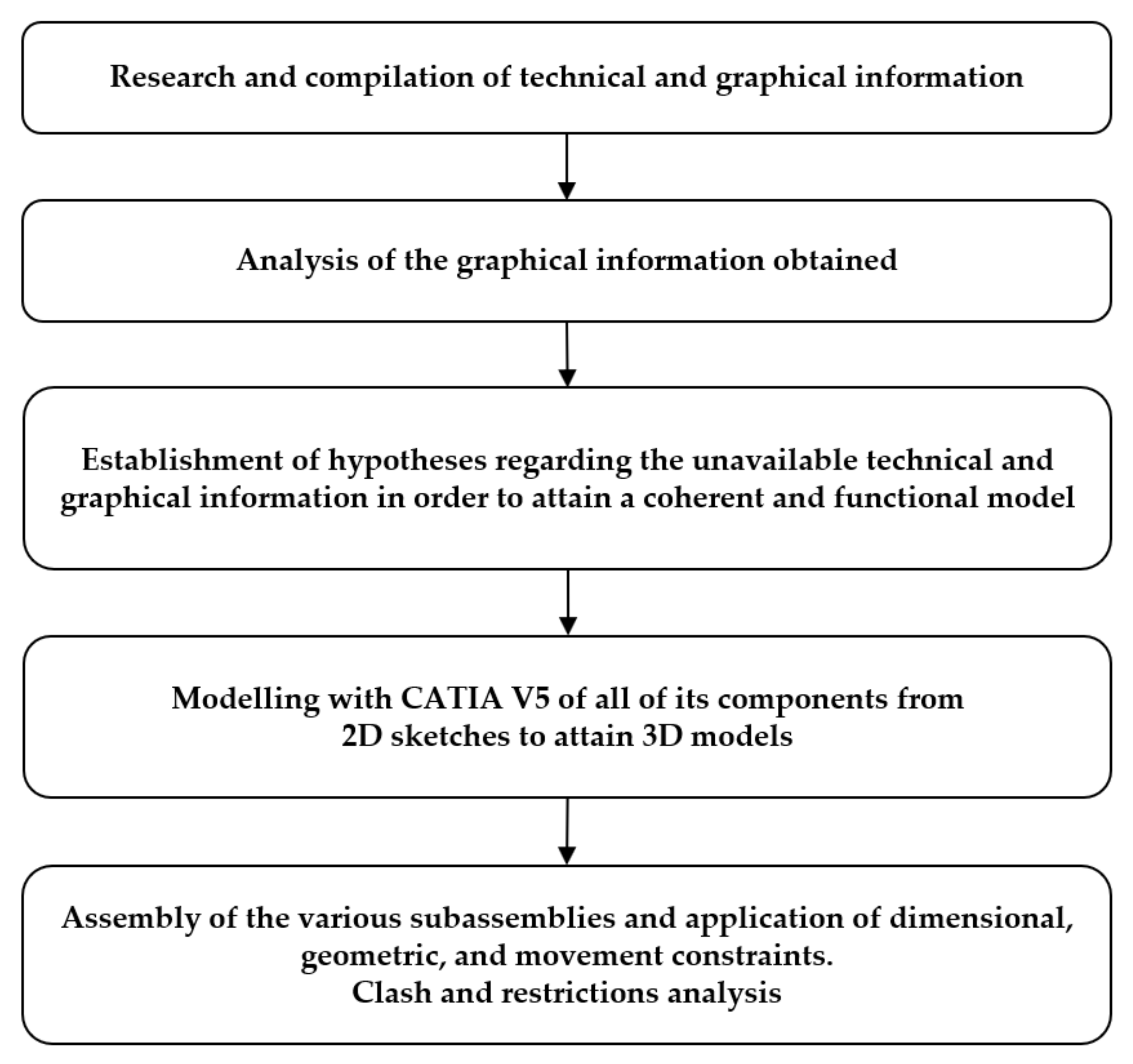
3.1. Considerations and Operation
In accordance with the information collected in plans and images, and after having studied the mechanism, the Robey and Co sugarcane milling machine was modelled using the CATIA V5 R20 software, with identical measurements to those mentioned in the reports of the time, and we verified their agreement with the dimensions of the plans used. Thus, the model has exterior dimensions of 5.33 m in length, 2.80 m in width, and a total height of 2.85 m. These measurements include those of elements, such as the juice collecting tank and the flywheel of the steam engine, that are outside the bedplate of the model. With this set of measurements, the remaining elements could be scaled, so that the entire 3D CAD model would have coherent dimensions and would be functional.
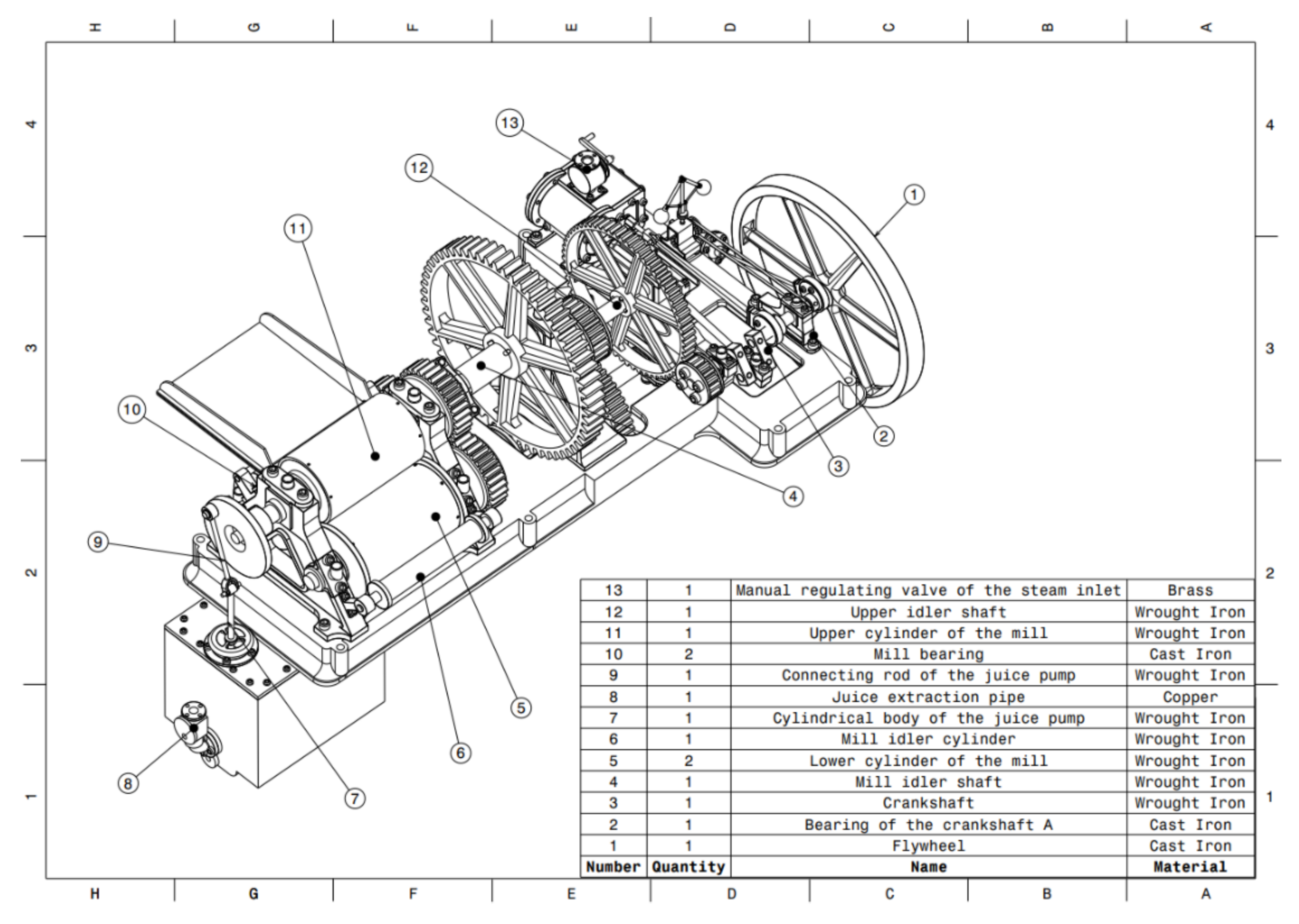
With this invention, sugarcane juice could be extracted in an industrial way, in addition to performing said extraction in a faster and more continuous way, by substituting animal traction for the force generated in a steam engine associated with the milling machine. In order to provide a clear and detailed explanation of the operation of the mechanism,
Figure 2,
Figure 3 and
Figure 4 are given, which are three assembly plans of the complete model, with the list of its comprising elements. An overview of the complete model can be appreciated in
Figure 2.
In
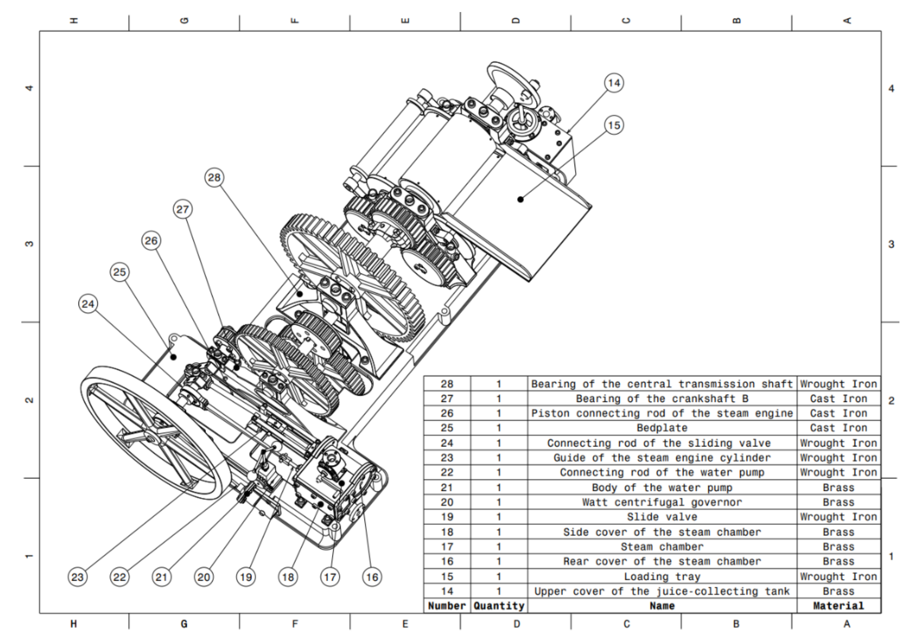
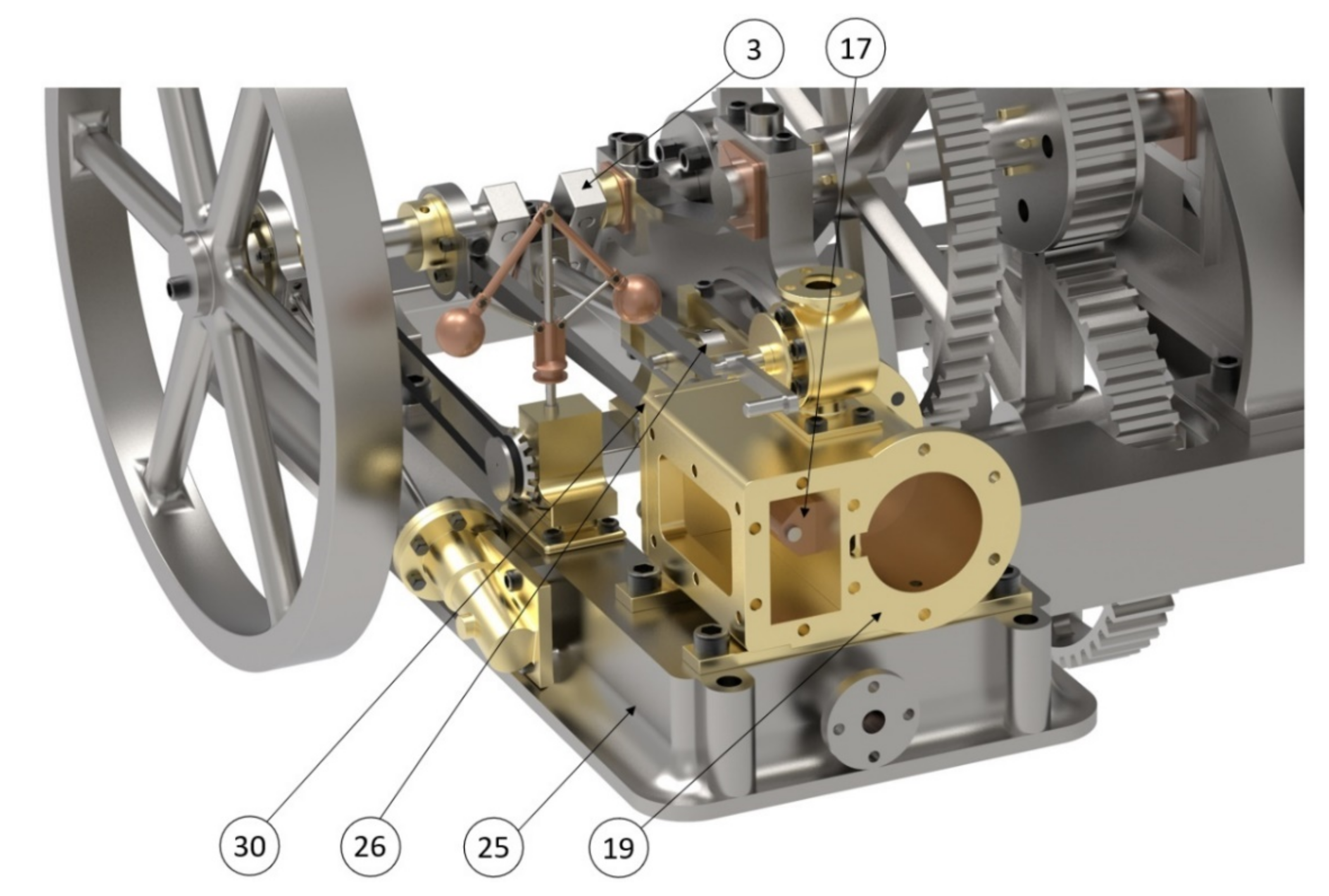
Figure 3, a rear view is observed to show the components of the steam engine more clearly, such as the steam chamber (17) and piston connecting rod (26).
In
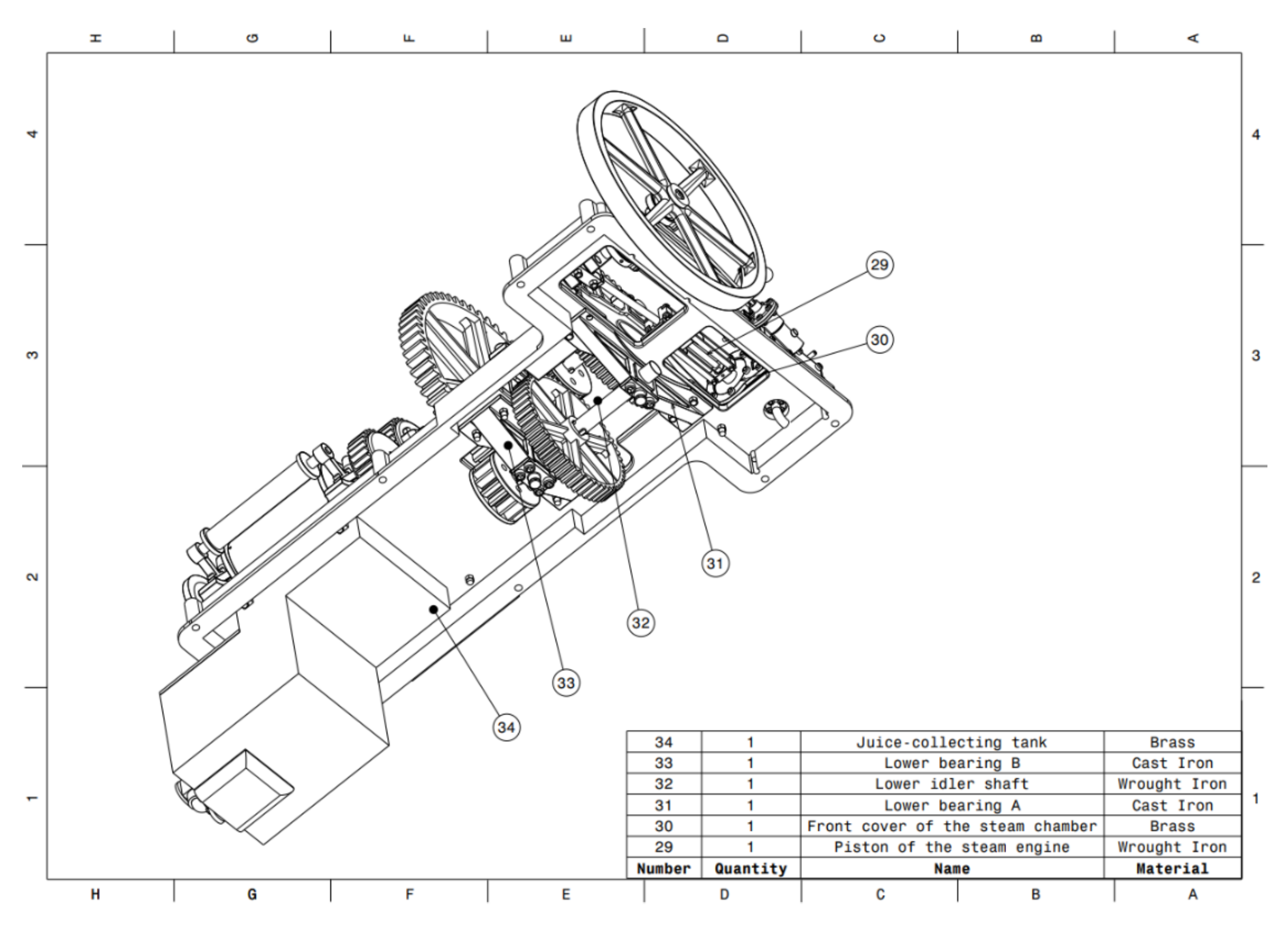
Figure 4, the lower part of the mechanism is shown, since there are components that are fixed beneath the bedplate (25).
As has already been mentioned, the machine presented was used for the milling of sugar cane; therefore, this mechanism possesses all the necessary elements for this purpose, although it does also include further components to render the milling process simpler and more continuous. This is due to the incorporation of a steam engine, associated with the mill, that is capable of propelling the mill, along with two hydraulic pumps. Said engine would be powered by a steam boiler through a connection of pipes. The boiler would be fed, in turn, from a tank that would supply the water by means of the cylindrical body of the water pump (21) and a connecting rod (22). Although the elements of the boiler, tank, and pipe assembly have not been modelled, they are worthy of mention, so that the complete operation of the engine can be understood. The reciprocating movement of the piston inside the body of the water pump (21) generates a vacuum, which causes the water to move in one direction, thanks to the placement of one-way valves. On entering the boiler, the water heats up and initiates the generation of the steam needed to power the engine. Likewise, in the pipe connecting the boiler with the engine, there would be a valve connected to the Watt centrifugal governor (20), which was in charge of automatically supplying the necessary steam to the engine, according to the speed of its rotation.
At this point in the explanation of the operation of the complete mechanism, it should be mentioned that all the components of the machine are fixed to a solid, cast-iron bedplate (25). Depending on the dimensions of the model, this bedplate could weigh up to 3 tons, thereby ensuring a stable fixation on a surface designed to hold the weight of the entire structure. It should be borne in mind that said bedplate was responsible for absorbing the vibrations generated by the engine and all the movements generated in the machine.
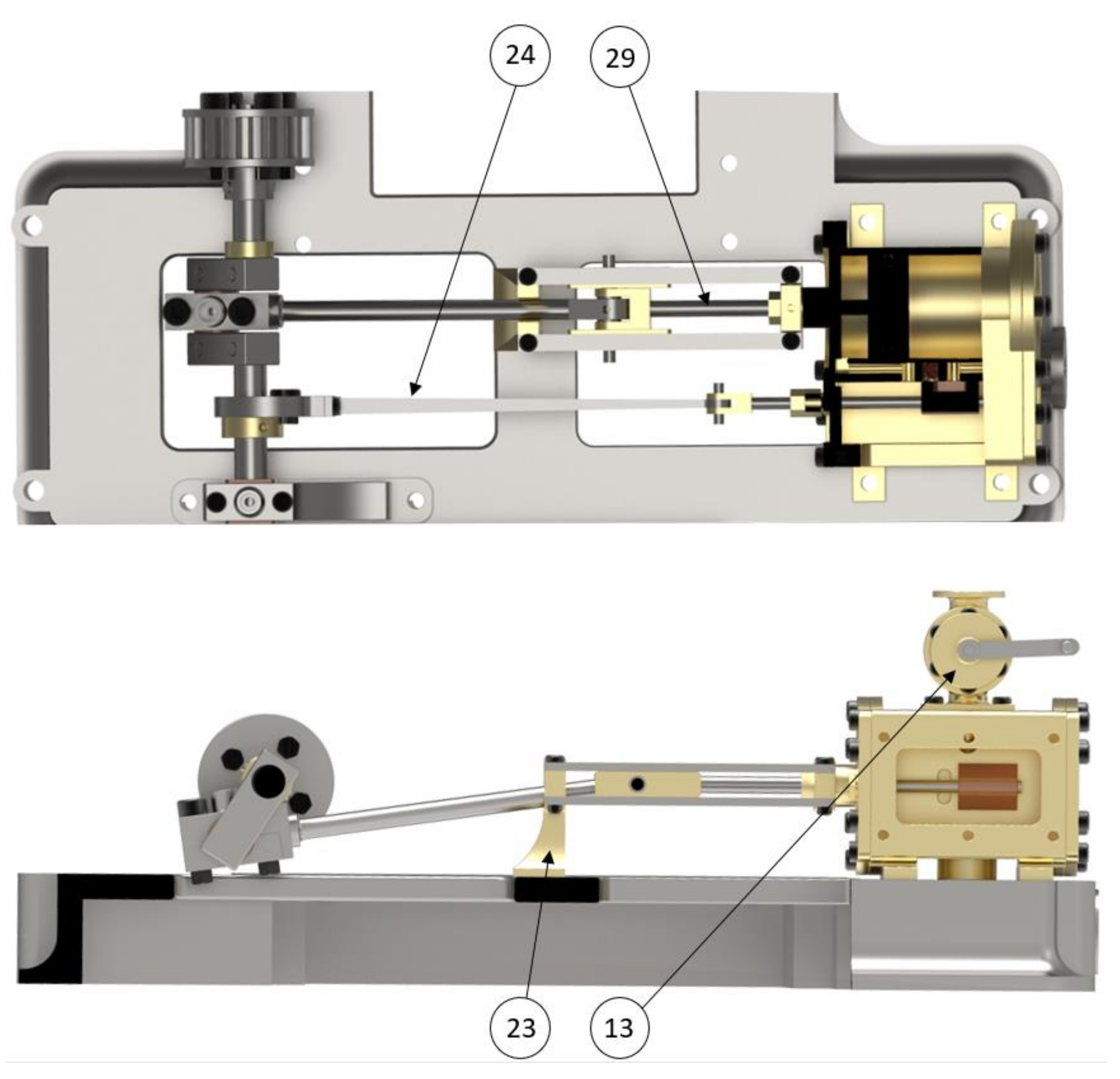
On the other hand, the steam enters the engine, and a manual regulating valve (13) is encountered, which, apart from regulating the inlet steam, can be used as a brake since, if it is completely closed, the steam cannot enter the steam chamber (17), thereby ending the supply of heat energy. Once the steam flow passes this valve, it enters the steam chamber, therein producing the exchange of heat energy from the steam and mechanical movement. To this end, three main elements intervene: the steam chamber, hermetically closed by rear (16) and side covers (18), both of which, in
Figure 5, have been removed to show the inside of the steam chamber, and thirdly, through a front cover (30), which allows the passage of the other two elements: the slide valve (19) and piston of the steam engine (29).
The first space that the steam encounters is the parallelepipedic area of the steam chamber; there, depending on the position of the slide valve, it will enter from one side of the piston or the other. Once inside the cylindrical zone, the steam, finding itself in a confined space, will exert pressure on one of the surfaces of the piston, causing it to move along the entire length of its path. When it comes to an end, the steam finds an outlet orifice, and, in turn, since it is a double-action motor, the slide valve will have changed its position, thereby allowing the steam to enter through the opposite part of the piston, making it now change the direction of the rectilinear motion. This circuit of steam is repetitive, thus managing to transform heat energy into mechanical energy and, therefore, producing the reciprocating movement in the piston. When the steam finds the outlet, it is evacuated through a lower conduit in the body of the steam chamber that would connect with a chimney.
Figure 6 shows two planar views, in order to easily clarify the piston-rod mechanism and functioning of the valves.
Having explained how the steam engine is capable of harnessing the energy of steam to transform it into mechanical energy, it becomes necessary to understand how this comes to be used for the milling (pressing) of sugar cane.
Given that the motor is generating a reciprocating movement, it is converted into a uniform circular movement by means of certain elements. The piston of steam engine ensures its rectilinear movement, thanks to the guide of the steam engine cylinder (23) that fixes its position with the connection to the front cover of the steam chamber and the bedplate itself. The piston of the steam engine is joined by means of an articulated joint (or ball joint) to the connecting rod (26), thanks to which it can transform the rectilinear movement into a circular movement. Said element has a length of 97 cm between the shafts; that is to say, the distance between the piston joint and the crankshaft (3) is practically 1 metre. In order to correctly carry out the transformation of the movement, the piston connecting rod of the steam engine joins the crankshaft in its eccentric zone, called the crank. This composition of elements ensures the change from a rectilinear reciprocating movement to a uniform circular movement.
In fact, to achieve uniform movement, another crucial element comes into play, the flywheel (1), which is a passive element of the engine of 1.70 m in diameter, whose function is to provide the assembly with additional inertia, in order to enable the kinetic energy to be stored. Due to the design of the double-action engine, the cylinder-rod-crankshaft assembly has two situations of maximum force, where the torque is generated; these situations coincide with the two limit positions, where the gas expands and displaces the piston inside the steam chamber. Due to the dimensions and mass of the flywheel, it opposes the sudden accelerations of the rotary movement, thereby rendering it uniform.
Having explained how the uniform circular movement is generated, it should be mentioned how the elements attached to the crankshaft take advantage of its movement. The water pump performs the pumping action through the movement of the piston that is attached to the connecting rod of the water pump itself; this, in turn, is attached to the crankshaft by means of a piece that generates the necessary eccentricity. On the other hand, the belt that transports the movement to the Watt centrifugal governor (20), which is in charge of admitting entry to the necessary steam, in accordance with the engine speeds required, is also attached to the aforementioned crankshaft. Adjacent to this belt, the connecting rod of the slide valve (24) is connected eccentrically to the crankshaft with free rotational movement. The relative position between the slide valve and the piston of the steam engine is defined by the union of their respective connecting rods on the crankshaft, where the angle, formed by the crank of the crankshaft and plate that supports the connecting rod of the slide valve, is 100°. This position ensures that the slide valve allows steam to enter through the side of the cylinder that has just expelled the steam. The flywheel is also attached to the crankshaft and is located outside the bedplate, due to its large dimensions. Finally, the first gear is found at the other end of the crankshaft. In order to ensure the correct rotation of the crankshaft and that no fluctuations in its movement are generated, the shaft of the crankshaft is held by the crankshaft bearings, A (2) and B (27), which are base bearings where the crankshaft performs its movement. In turn, these two bearings are firmly anchored to the bedplate.
On the other hand, the milling (pressing) of the sugar cane requires considerable compression force. However, the steam engine generated very high speeds that were unsuitable for milling, and it was, therefore, necessary to transform speed into force by means of a compound gear train (
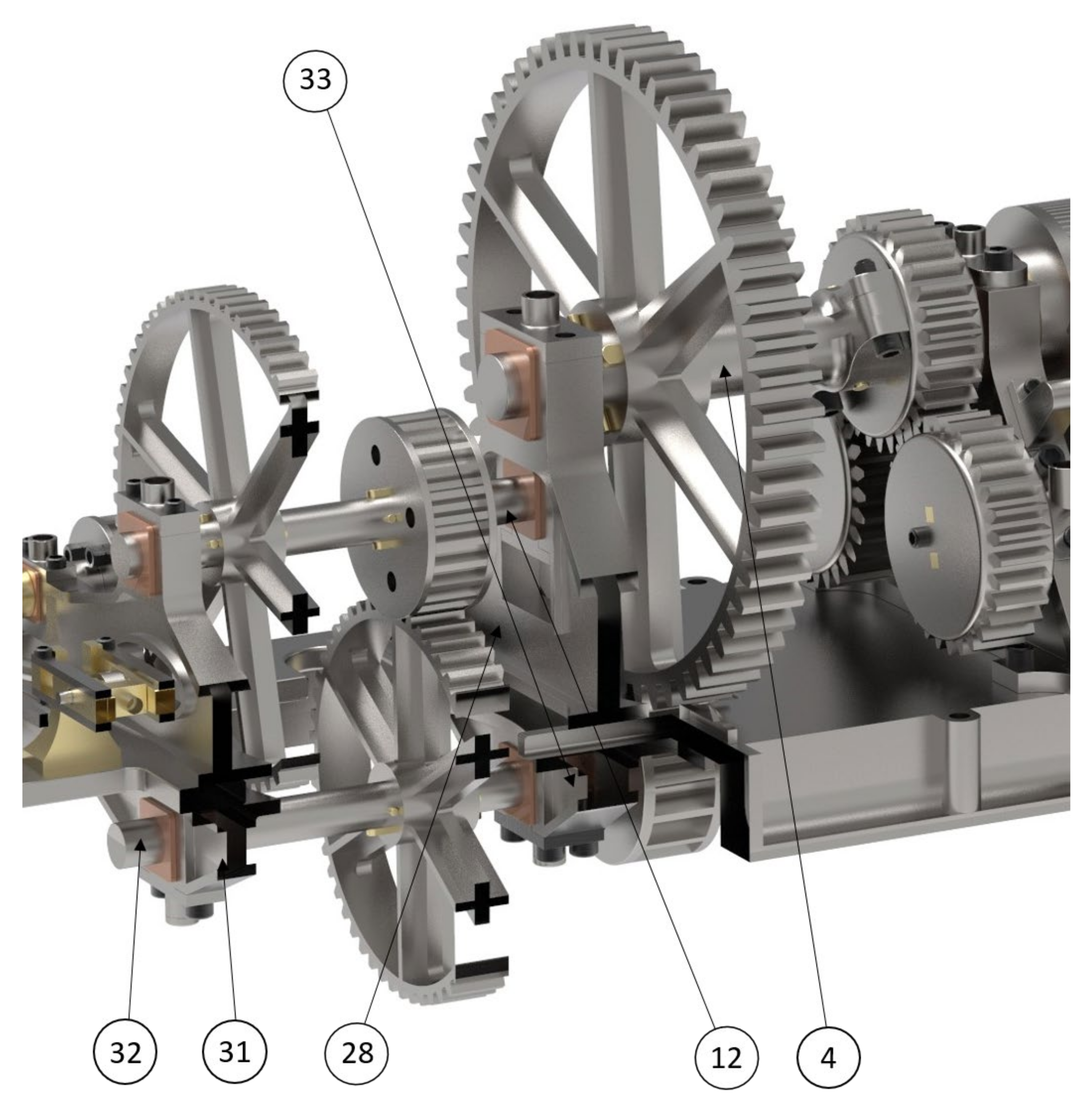
Figure 7). The supports of the shafts, where these gears are placed, as in the crankshaft, are bearings that are anchored to the bedplate. The crankshaft bearing B serves as a support for both the crankshaft and the upper idler shaft (12), which consists of two cogwheels. The other end of this upper idler shaft rests on the bearing of the central transmission shaft (28). Said bearing is also responsible for serving as a support for the last shaft of the gear train, called the mill idler shaft (4), which is the largest gear in the mechanism, and consists of 60 teeth, distributed over a 1.62 m diameter circumference. In order to connect the set of gears of the upper idler shaft and the mill idler shaft, the lower idler shaft (32) is utilised. This exerts its rotary movement, subject to the lower bearings A (31) and B (33), which, in turn, are anchored to the bedplate by screws. The positions of these two bearings coincide with those of the crankshaft bearing B and the bearing of the central transmission shaft, respectively, thereby taking advantage of the orifices, in order to be fixed to the bedplate. The main function of this gear train, which consists of six cogwheels, is to multiply the force by reducing the turning speed; that is, the set of gears would act as what is commonly known as a reducer.
Once the transmission and multiplication of forces is achieved through the gear train, then the upper idler shaft is connected collinearly with the upper cylinder of the mill (11), by means of a rigid connection at three points.
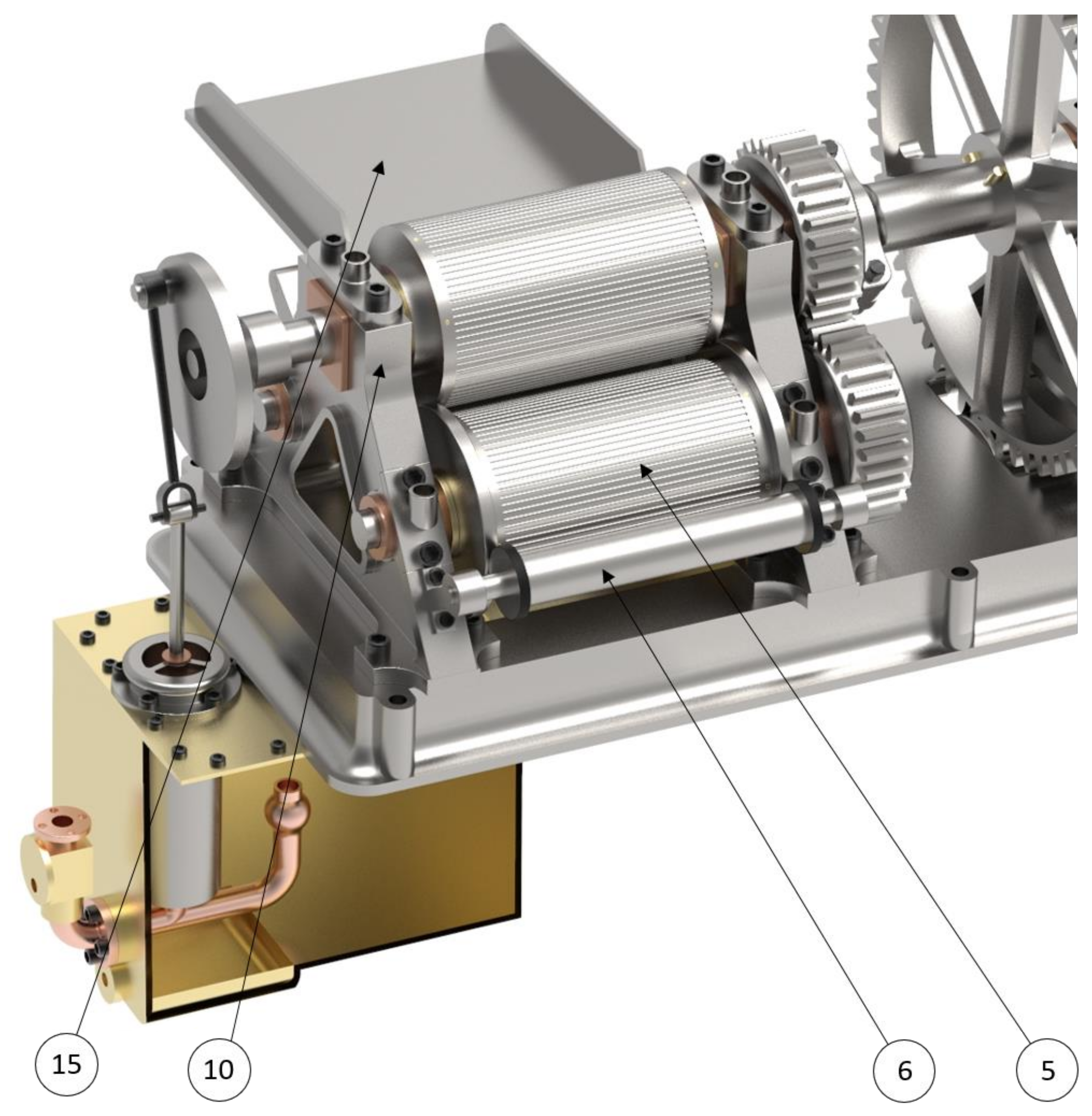
The milling system consists of three cylinders, arranged in a pyramidal shape (
Figure 8), thanks to the anchoring position of the mill bearings (10). The upper cylinder and two lower cylinders (5) are placed therein. The movement of the mill is ensured, thanks to the incorporation of a gear in each shaft of the cylinders. The upper cylinder transmits the energy between the other two cylinders through these cogwheels, thereby achieving the milling (pressing). Likewise, the sugar cane is introduced perpendicularly into the cylinders through the loading tray (15), which is also anchored to the mill bearings; these cylinders have a rough or grooved surface to ensure their grip on the stems of sugar cane. The upper cylinder, together with the lower cylinder, placed closer to the loading tray, perform a pulling movement on the cane, pressing it between the two cylinders, while the upper cylinder with the other lower cylinder assembly manages to eject the cane at the same time as it makes a second pressing. On the other hand, the sugarcane stems are prevented from re-entering the mill by the mill idler cylinder (6), and the mill outlet is also connected to a conveyor belt to prevent the accumulation of pressed sugarcane stems.
Finally, it should be mentioned that not only was the function of the invention that of a sugarcane mill, but the energy and movement generated by the steam engine was also used to pump the sugarcane juice obtained. As the sugar cane passed through the cylinders, it was pressed, allowing the juice stored in the stems to fall into the juice collecting tank (34), this being covered by an upper cover (14) that provided support for the cylindrical body of the juice pump (7). It appears that said collecting tank would use a mesh to filter the juice and to detain any pieces detached during pressing from passing through. Likewise, the juice collecting tank, fixed to the bedplate, would also house the cylindrical body of the juice pump, which has a piston that moves vertically, thanks to the transformation of the movement of the connecting rod of the juice pump (9). This connecting rod is eccentrically connected by means of a joint to the shaft of the upper cylinder of the mill, in order to achieve the correct path of the piston in the body of the juice pump. Said element is able to push the juice through the juice extraction pipe (8) in two movements.
When the pump piston is raised, the juice enters through a one-way valve, located inside the collecting tank, which allows the fluid to pass in only one direction, thus filling the pump cavity. In the juice extraction pipe, located at the outlet of the collecting tank, there is another unidirectional valve that closes during the lifting movement of the piston, thereby preventing the return of the juice already driven. At the moment, when the piston begins its downward movement, the liquid closes the one-way valve through which it had entered and opens the valve that remained closed, thus pumping the juice from the collecting tank into the extraction pipe, which was probably connected to decanters, barrels, or storage tanks.
3.2. Modelling of Elements and Assembly of Subsets
The historical invention, analysed in this research, was an industrial machine composed of a variety of parts of different sizes. The objective of this modelling is to make an approach as similar as possible to the original machine, by modelling all the parts that would have been manufactured in this way and their subsequent assembly. In total, 152 files (CATPart) have been created, which constitute the modelling of each and every one of the pieces that make up the set, as a whole. Likewise, to facilitate the understanding of said machine, the modelling of the pieces will be presented by grouping them into various subsets, differentiated by their functionality.
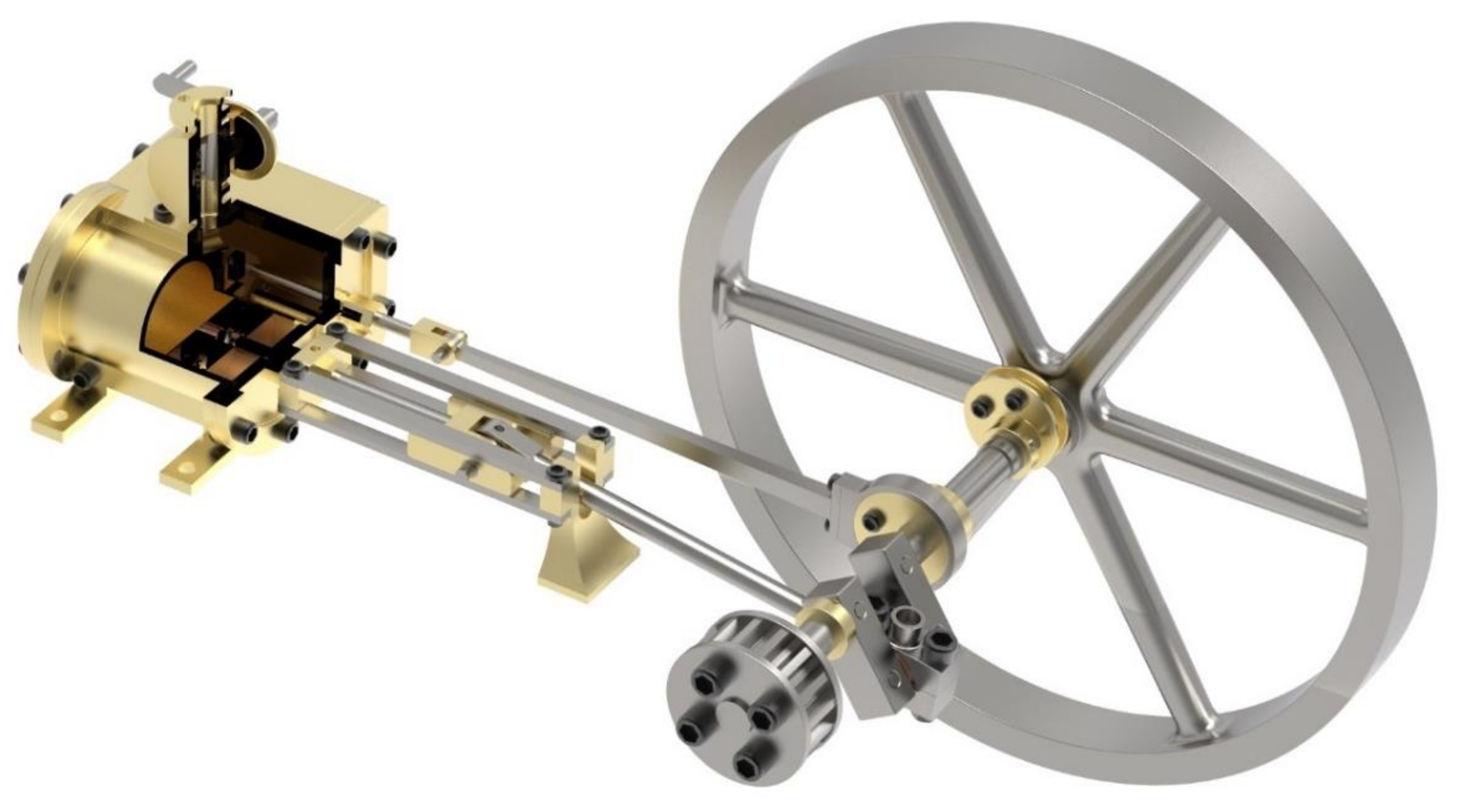
3.2.1. Steam Engine Modelling
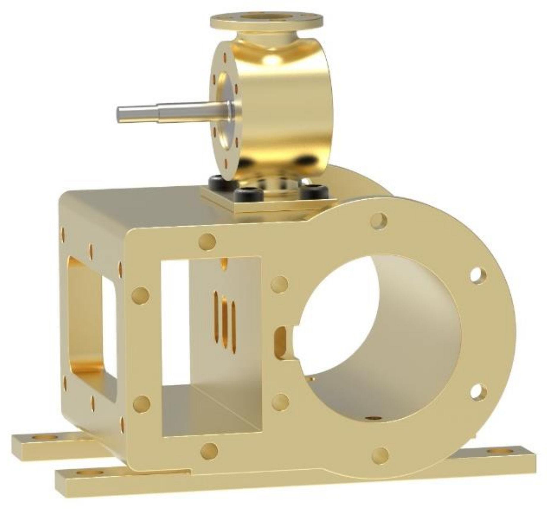
The mechanism that makes up the steam engine can be divided into three clearly differentiated subsets that interact with each other: the steam chamber, piston and slide valve kit, and, finally, crankshaft.
In the steam chamber, the gas is distributed and generates the thrust on the piston. Before entering said chamber, the steam finds a shut-off valve where it can regulate or completely cut off its inlet. The steam chamber has two internal cavities: the parallelepipedic zone and the cylindrical zone. The slide valve, in charge of distributing the steam through one of the three existing orifices, is housed in the parallelepipedic area. In relation to the distribution orifices, the steam chamber has one in its upper part where the steam enters and three where it is distributed; of these latter three, the two at the ends of the chamber connect the antechamber with the piston chamber, while the central orifice is the gas outlet used in the expansion of the piston.
The cylindrical area, where the piston is housed, has two holes in its lower part to purge the condensed steam while the machine was in operation.
Figure 9 shows the two indicated areas, from which the closing covers have been removed, so that their interior can be observed.
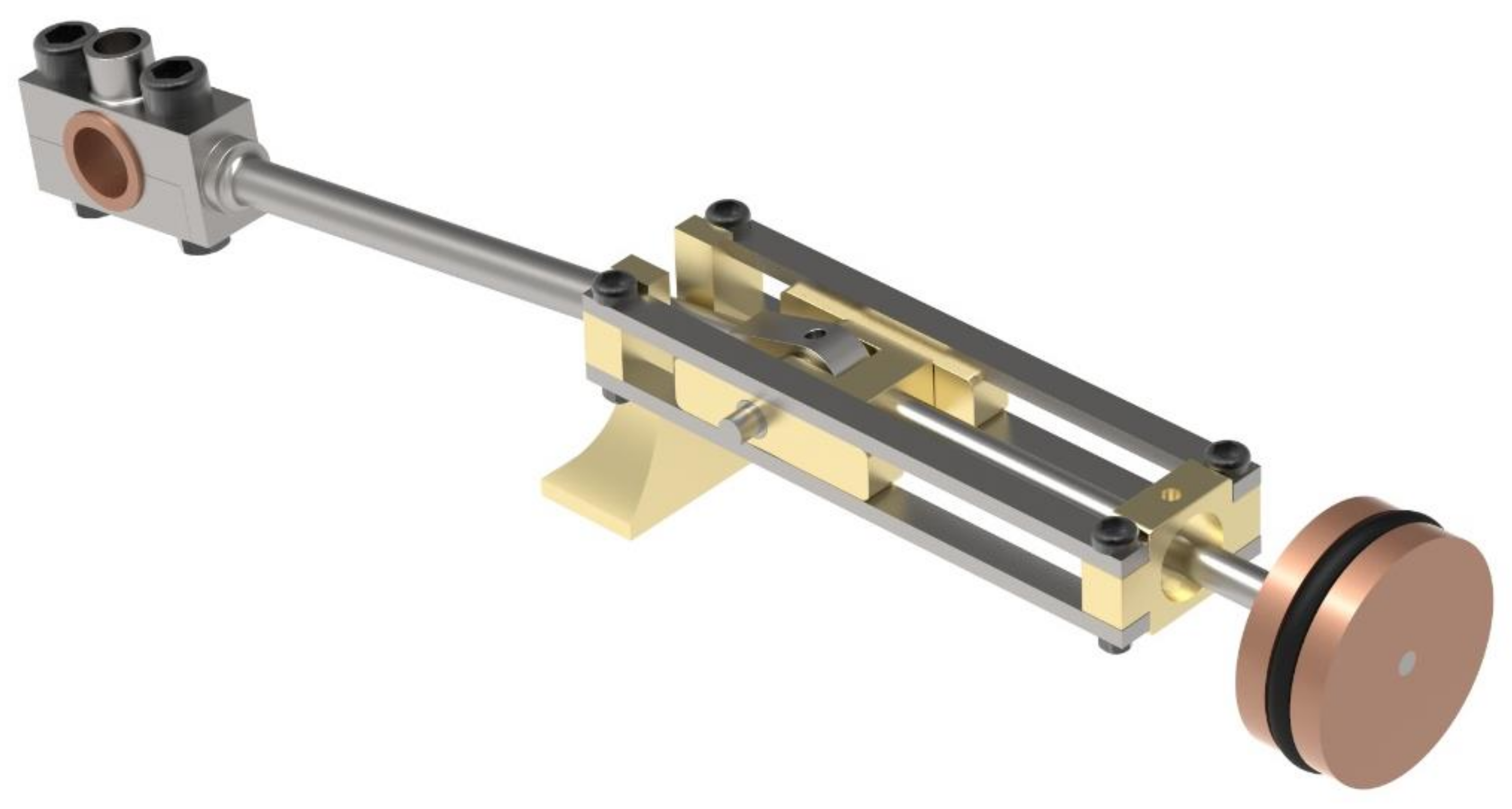
Figure 10 shows the piston subassembly (union between the piston and its connecting rod), where the straight guide is also incorporated, which ensures that the piston does not vary its reciprocating trajectory. The piston is in charge of transforming the steam pressure into kinetic energy. By bearing in mind the dimensions of the piston, its path in the steam chamber, and that it is a double-action engine, this engine can be assumed to have had an approximate volume of 39 litres. Although this value is extremely large for today’s engines, it must be borne in mind that the performance provided by steam in the middle of the industrial revolution was very low, compared to performance today.
Likewise, the piston has an O-ring around its perimeter that ensures a seal between each side of the piston; attached to the piston is the connecting rod, responsible for transforming the rectilinear movement into a rotary movement. These two elements are joined by means of a ball joint, which has an orifice for its lubrication and greasing.
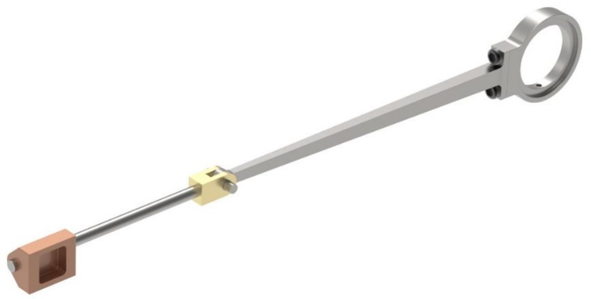
The slide valve (
Figure 11) is located parallel to the previous subassembly. This element is crucial for the correct operation of the engine, since it is responsible for distributing the steam in an alternate way, by interspersing the outlet and inlet ducts in the steam chamber. The element that causes the ducts to interchange is a hollow bronze cube, open on one of its faces, that creates a duct between two of the three orifices in the steam chamber. The valve can move, thanks to the movement transmitted by the crankshaft, by means of the incorporation of a connecting rod between the two elements with an articulated connection at both ends. That is to say, in this case, the movement is transmitted in the opposite direction to that of the piston, by converting the circular movement into rectilinear movement.
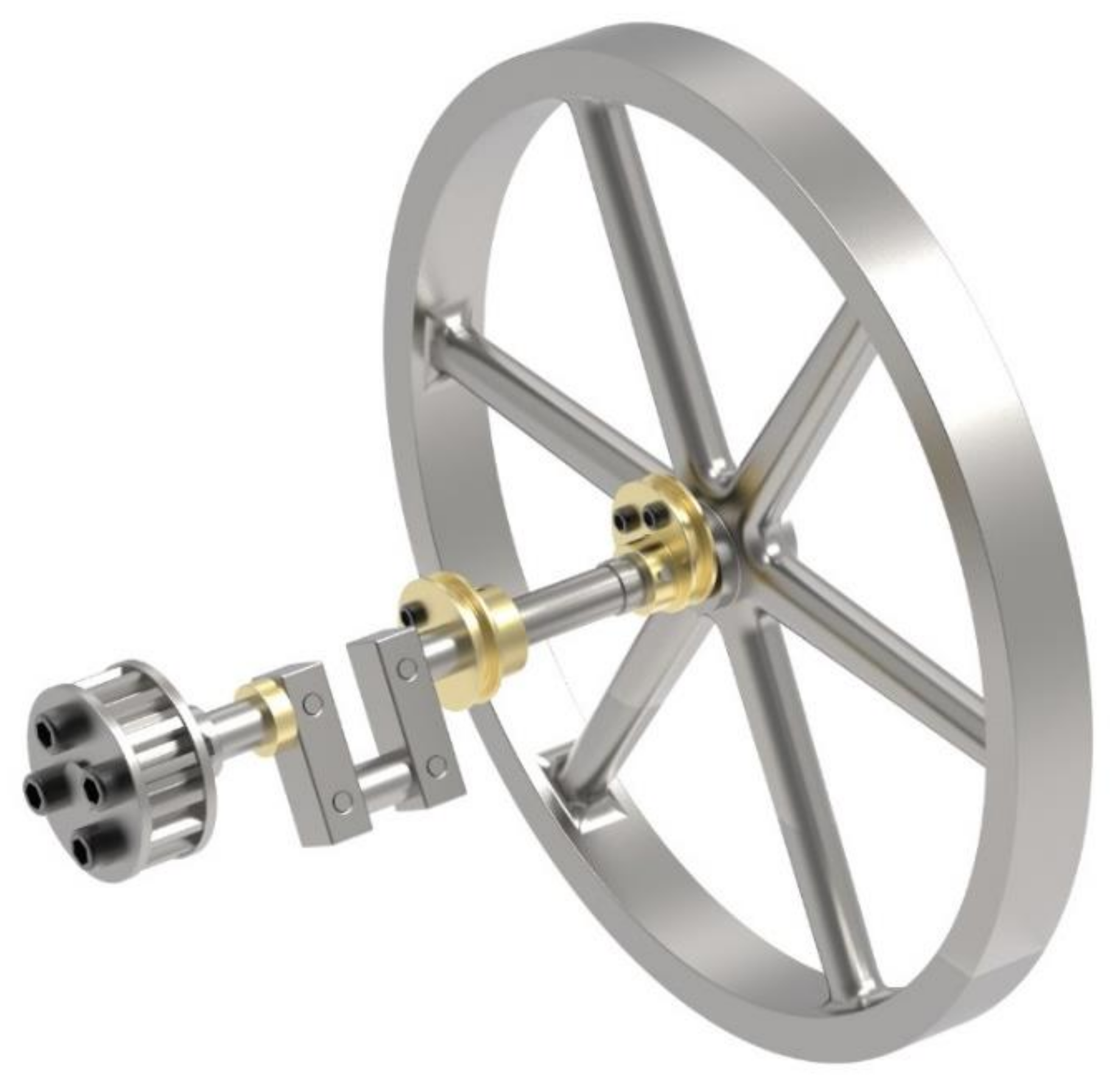
Finally, there is the subassembly of the crankshaft (
Figure 12), which is responsible the rotary movement of the piston connecting rod and transmitting it around a shaft to obtain a uniform circular movement. To this end, a crank is utilised, where the piston connecting rod joins the crankshaft, in an articulated way. Other elements, such as the water pump and the Watt centrifugal governor, are attached to the crankshaft. The flywheel and the transmission gear that connects with the gear train are also anchored in the crankshaft.
Finally,
Figure 13 shows the assembly of all the aforementioned subsets that make up the steam engine. Therefore, a double-action steam engine is presented, with a cut-out in the steam chamber to clearly show the connection between the steam chamber and the other components.
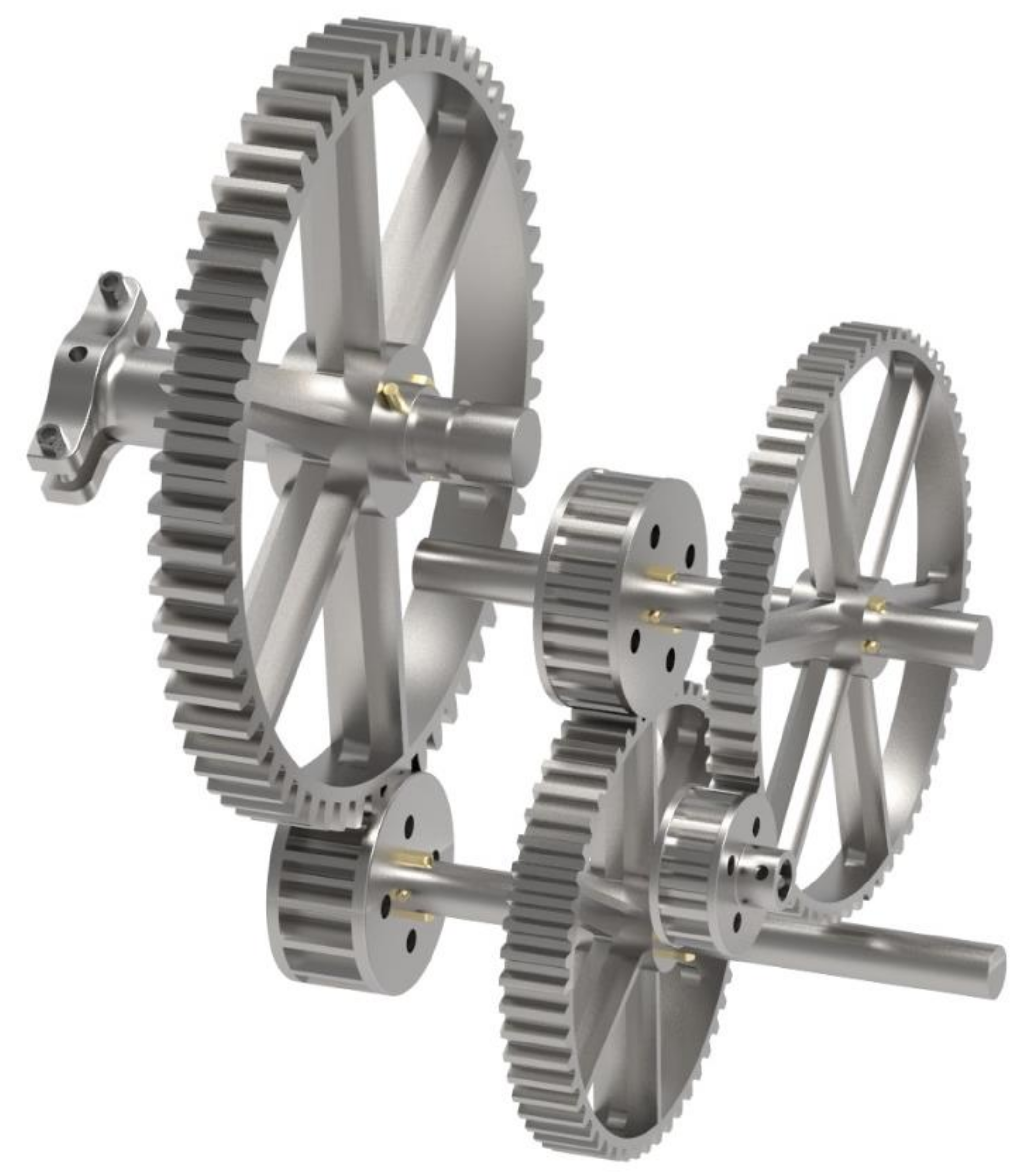
3.2.2. Gear Train Modelling
The machine features a gear train to increase the force transmitted, despite the decrease in the rotational speed. This is achieved by combining toothed wheels (gears) of different sizes that interlock with each other. The gears, shown in the model, are flat toothed wheels, whose teeth come together to transmit forces. Through a set of small driving gears and large driven gears, the desired effect is achieved. The mechanism has a repetitive structure, where a driving gear of small diameter (with few teeth) interlocks with a gear of large diameter (with numerous teeth), and, on the shaft of the latter, the next small gear is coupled, and so on.
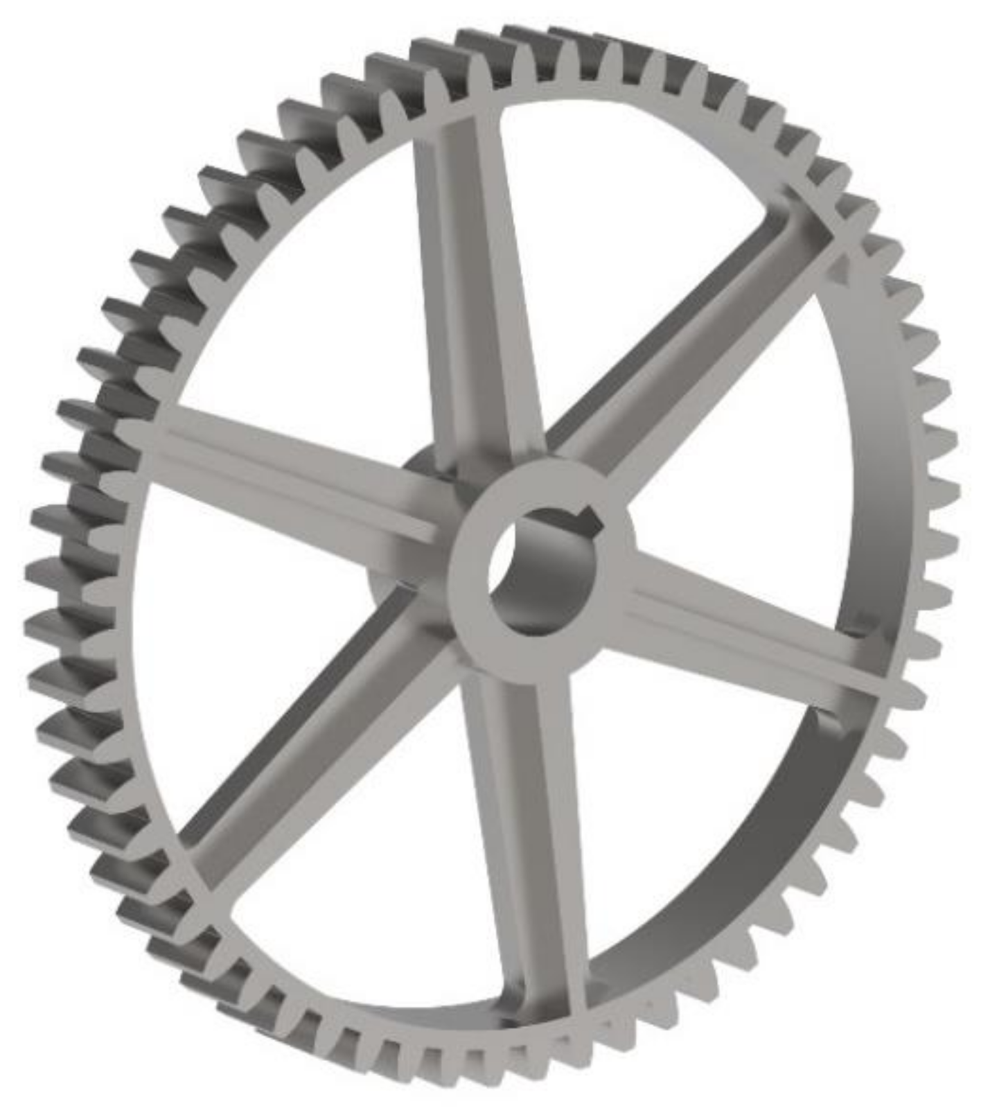
Large gears, which are driven, present a model in which the crown of teeth is connected to the centre by six spokes, separated by an angle of 60°, which causes the weight of each of these gears to decrease. Each gear has a slot in its central orifice, designed to place the cotter pin, which ensures that the force is correctly transmitted between the gear and the shaft. A total of three driven gears are found in the model, with pitch diameters of 95, 117, and 156 cm and totals of 53, 64, and 60 teeth, respectively. The largest thereof is shown in
Figure 14.
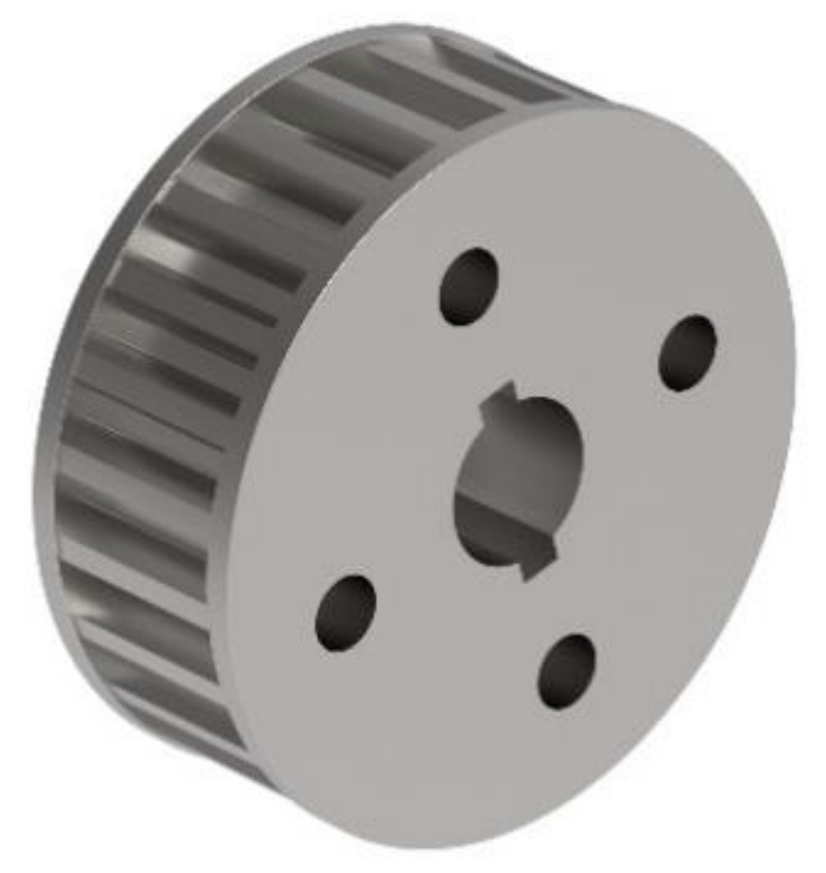
Driving gears (
Figure 15) are those that exert force on driven gears, that is, those that transmit the force; although, in certain mechanisms, a driven gear may also be a driving gear when it transmits force to yet another gear. In the case of the present invention, and due to the intention to increase the torque, the gears with a smaller diameter act as driving gears. The dimensions of the pitch diameters are 29, 40, and 45 cm, with a total of 16, 15 and 25 teeth, respectively. In addition to the orifice for the placement of the cotter pins, these gears feature side covers to ensure that the toothed wheels rotate on the same plane.
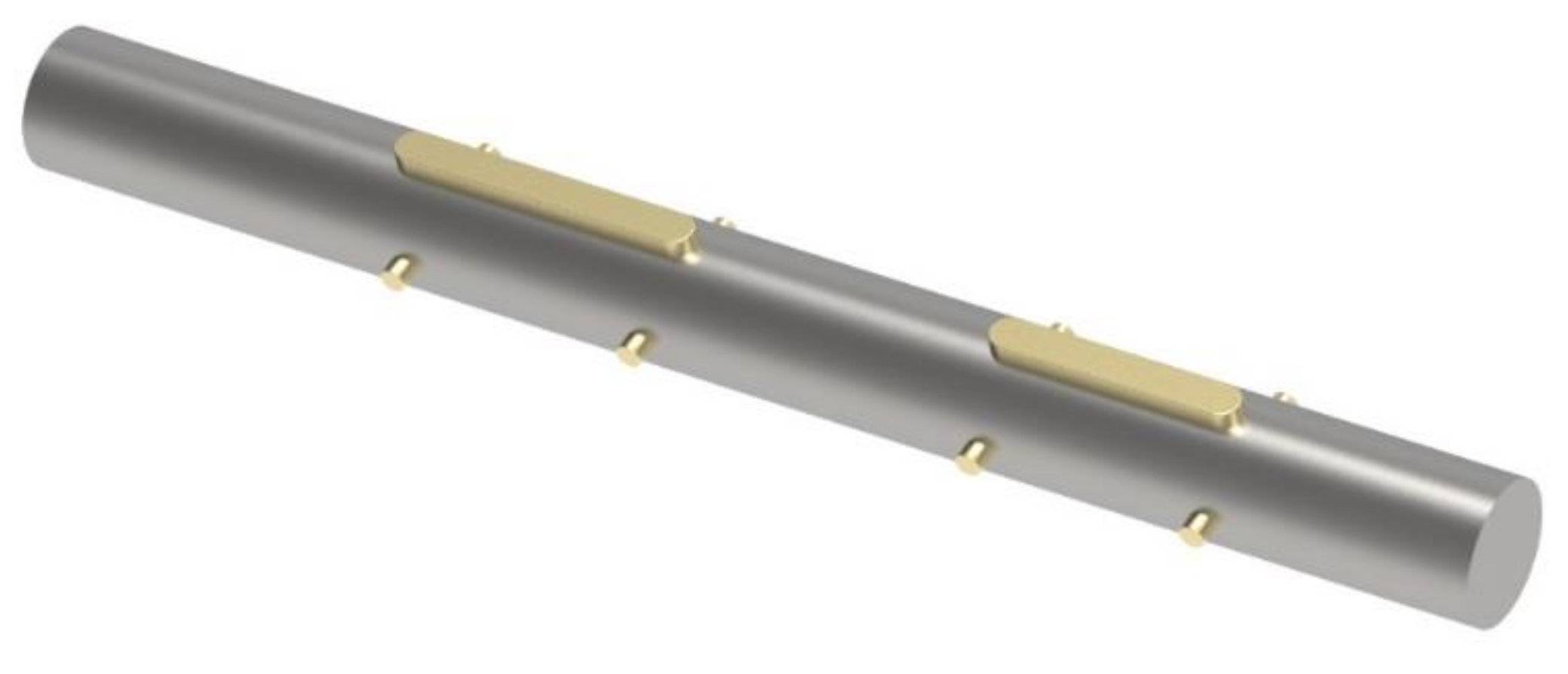
The shafts are modelled as solid cylinders that perform the functions of carrying the toothed wheels with them and transmitting movement between the shafts. These are elements subjected to great bending and dynamic fatigue, due to their rotary movement; although, the fact that they are cylindrical does improve their torsional rigidity, while ensuring the rotation of the bearings. Likewise, the shafts ensure the fixation of the toothed wheels, thanks to the cotter and dowel pins (
Figure 16).
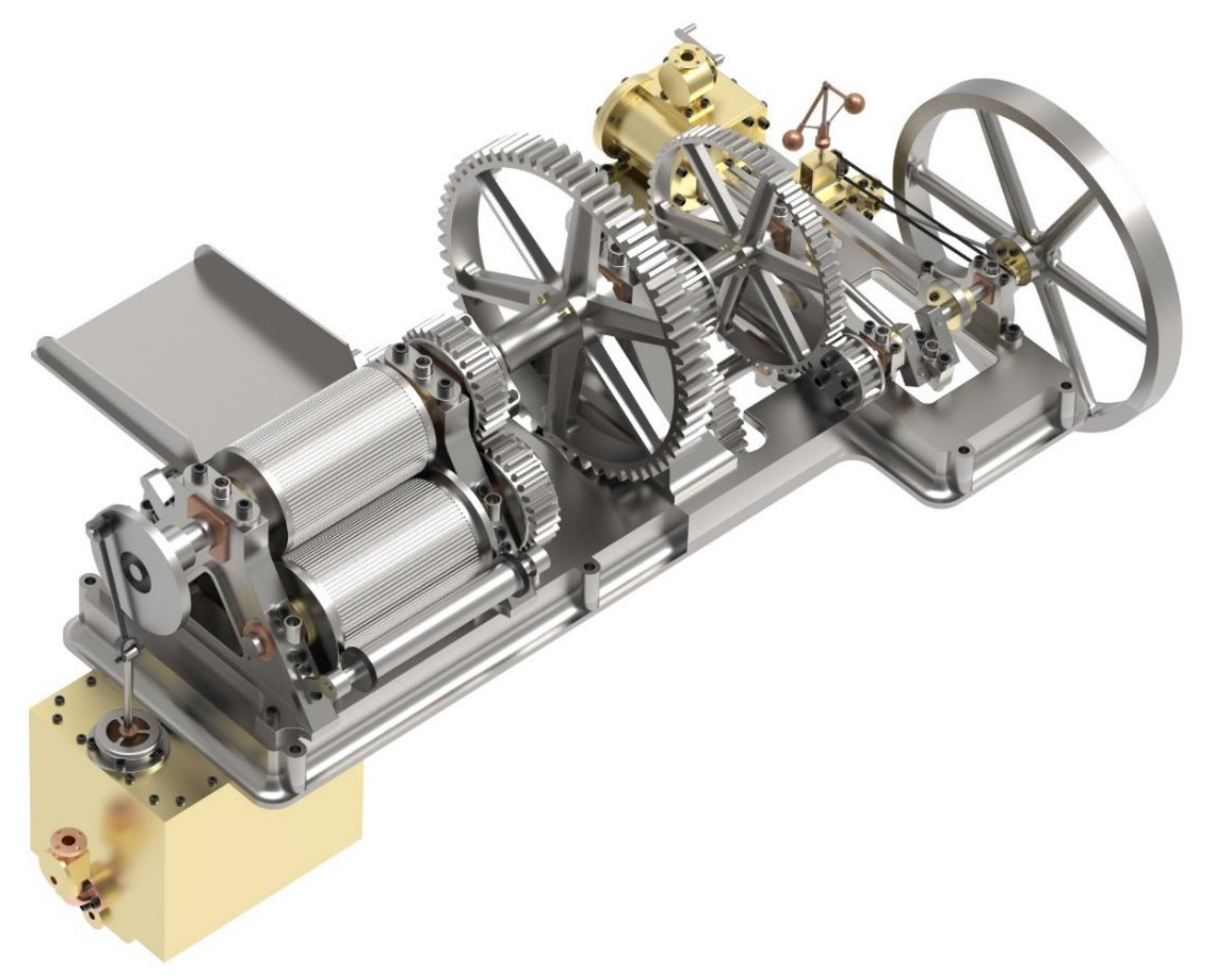
Figure 17 shows the final assembly of the complete gear train, where the three aforementioned subassemblies have been perfectly assembled: driving gears, shafts, and driven gears. It should be borne in mind that the first driving gear is connected to the crankshaft.
3.2.3. Milling-Mechanism Modelling
Regardless of the bearings that hold the mill shafts, this mill has three milling cylinders: a loading tray, idler cylinder, juice pump, and juice collecting tank. The cylinders are hollow and have a diameter of 51 cm, length of 85 cm, and wall thickness of 3.5 cm.
In order to be assembled with the shaft, end covers are utilised with the central orifice to house the shaft and six orifices within the diameter, in order to enable the cylinders to be fixed and prevent them from slipping. Each cylinder has a gear at one end, so that the upper cylinder, which receives the energy from the gear train, can transmit the force to the lower cylinders. The upper cylinder subassembly is shown in
Figure 18. The difference between this and the lower cylinders is that the other end of the shaft has an eccentric plate to join the connecting rod of the juice pump.
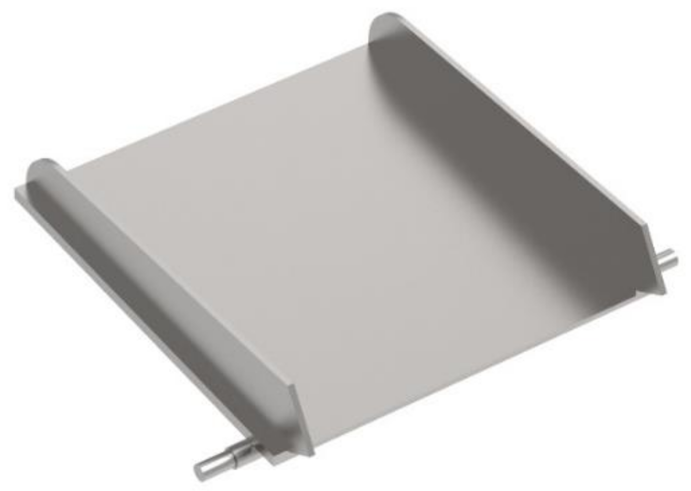
On the other hand, the function of the loading tray (
Figure 19) is simply that the mill is continuously supplied with sugarcane stems.
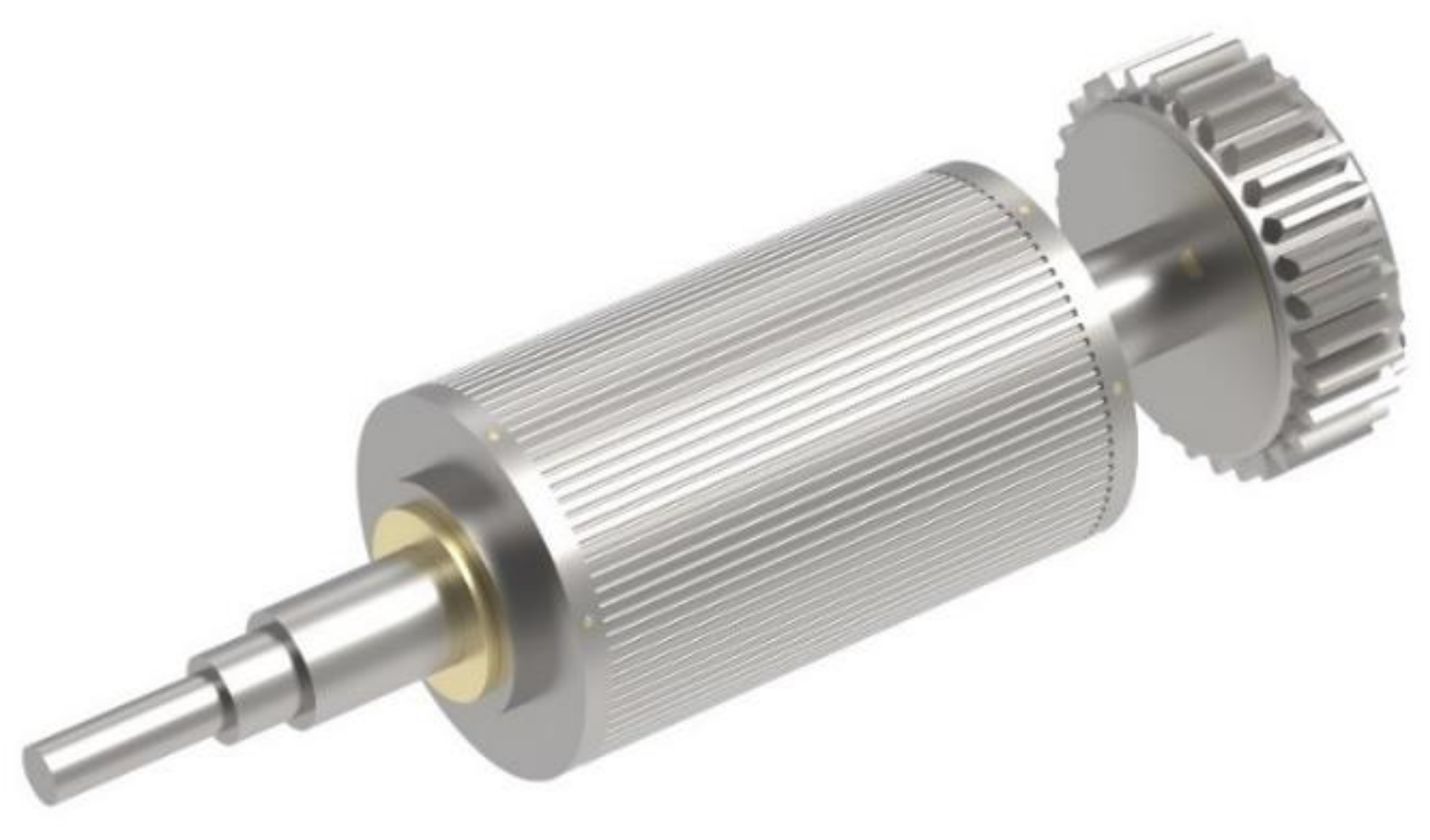
On the other hand, the idler shaft (
Figure 20) has the function of connecting with a conveyor belt, which causes the belt to move in the direction of the crushed cane output and moves the cane residue away from the machine to avoid an accumulation of material. Furthermore, this shaft has a rubber coating on the friction wheels to ensure sliding.
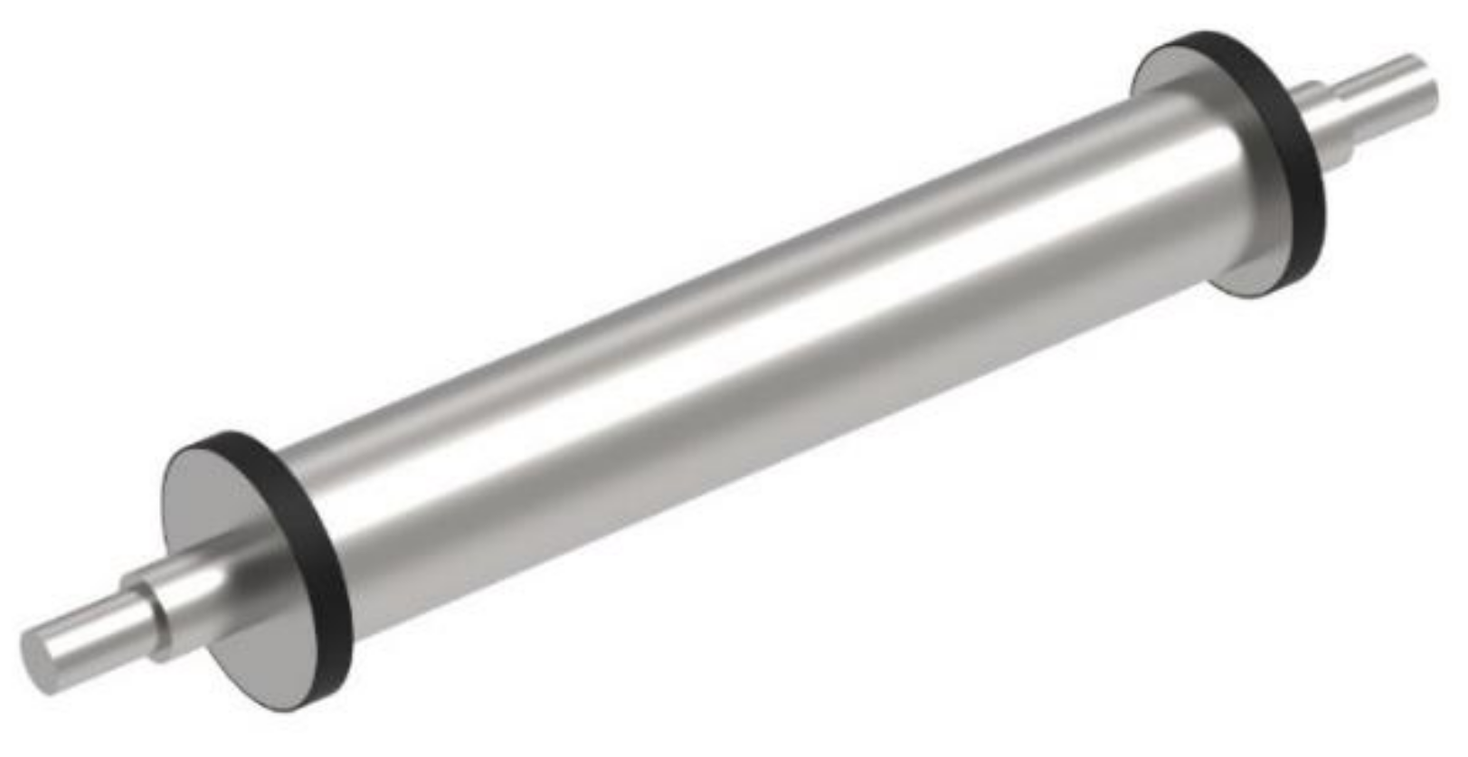
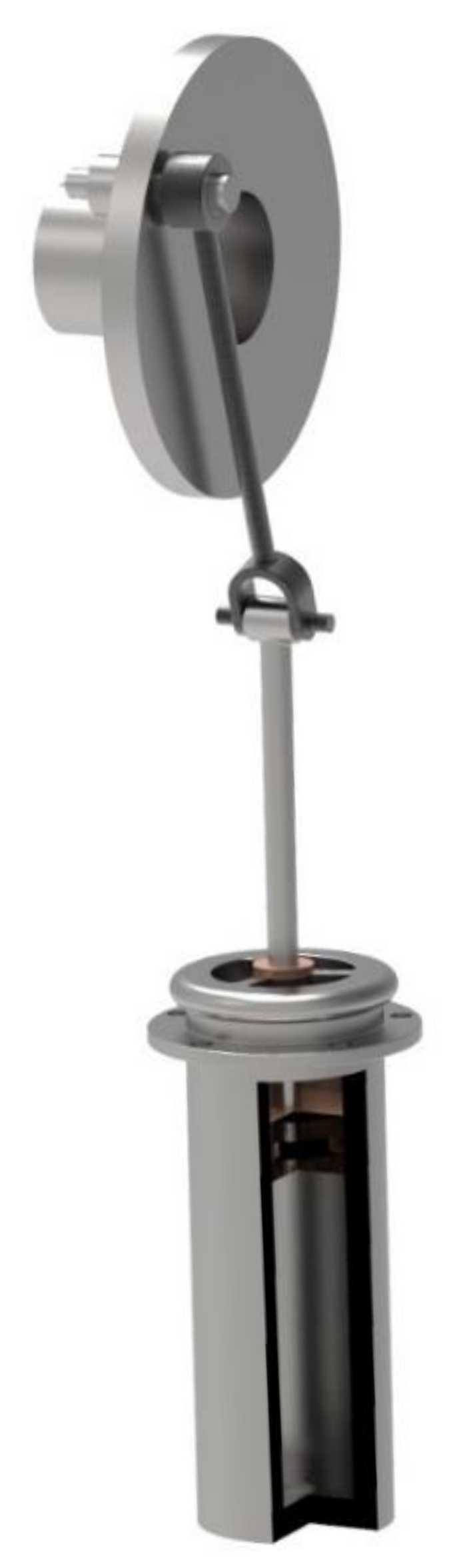
Likewise, the juice pump (
Figure 21) has the main function of pumping the extracted juice, accumulated in the collecting tank. This is composed of a connecting rod that transforms circular movement into a reciprocating rectilinear movement. Given the path of the piston and its diameter, the capacity of the pump can be assumed to be approximately 13 litres. Furthermore, according to the information collected, it is known that the standard turning speed of the mill is 5 rpm, which means that the machine would, theoretically, be capable of pumping 65 litres per minute.
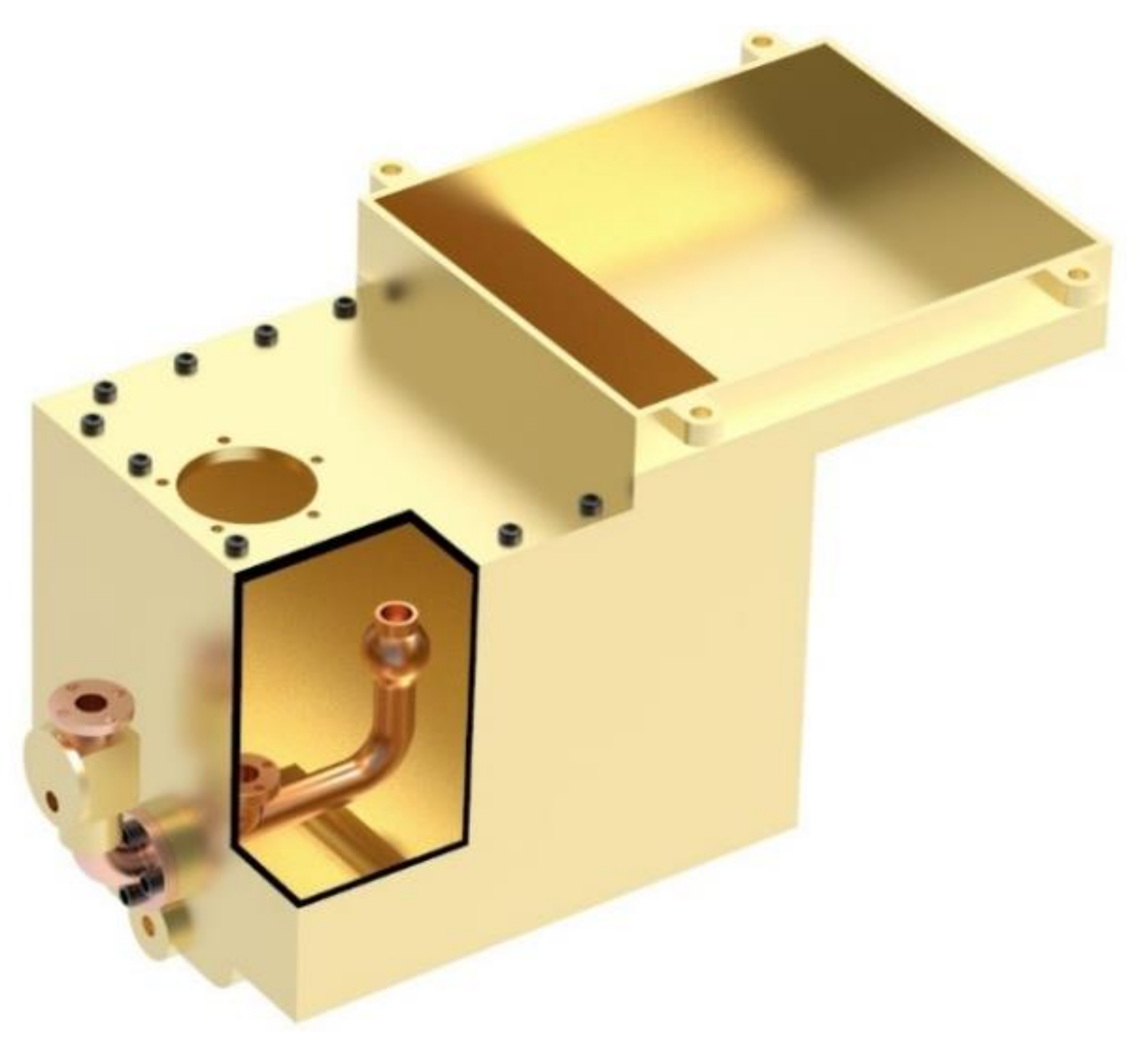
On the other hand, the juice collecting tank (
Figure 22) is a container where the juice, squeezed from the sugarcane, falls. According to the information collected, this element is capable of holding 130 imperial gallons, that is, 590 litres. This data gives an idea of the amount of juice that the milling of sugar cane could generate. Likewise, this element also presents a set of pipes, with one-way valves, to enable the pumping mechanism.
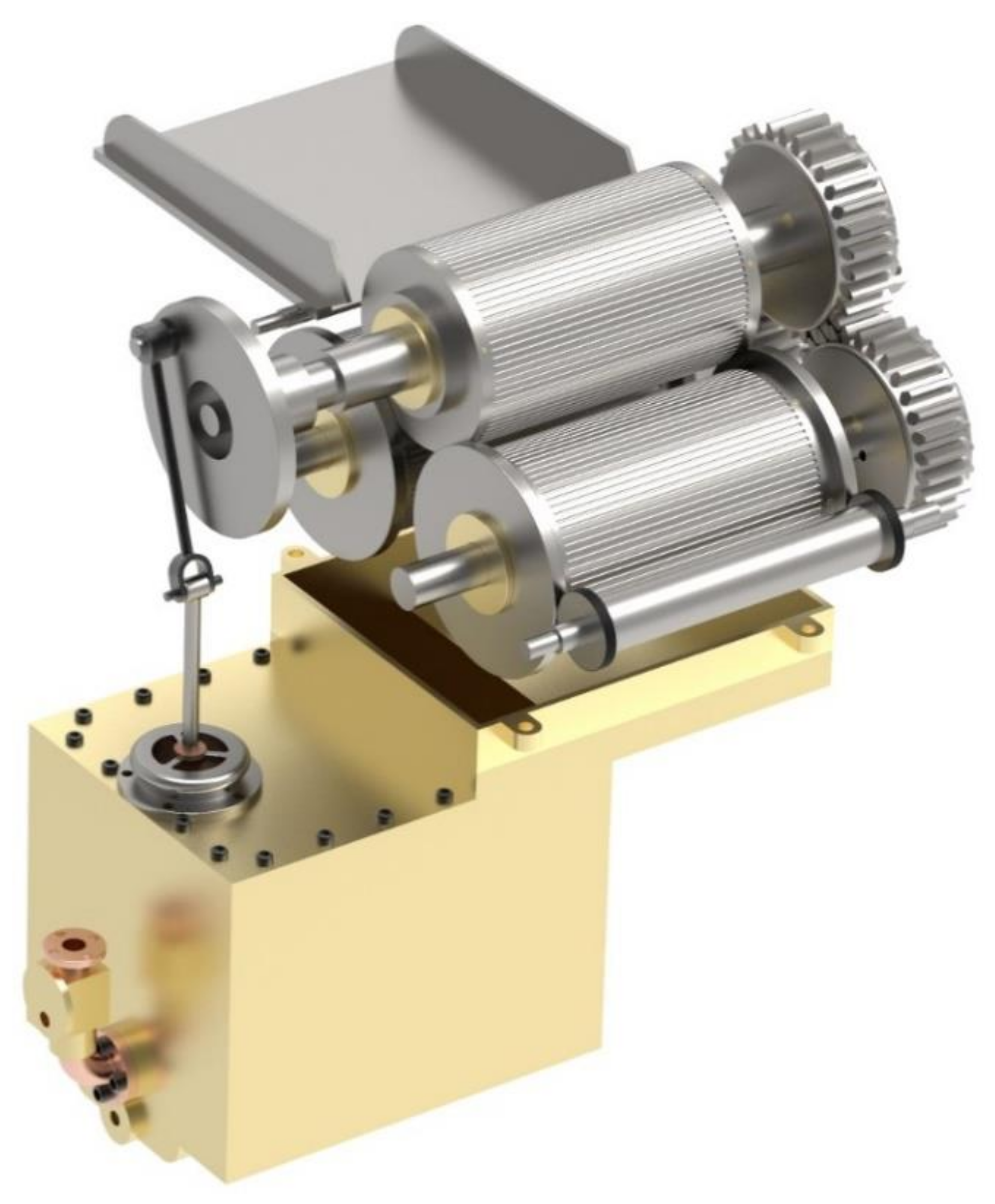
The final assembly (
Figure 23) of all the aforementioned subassemblies, forms the milling mechanism that would be joined by the upper shaft to the shaft of the last sprocket of the gear train.
3.2.4. Base Modelling
The purpose of the base is to fix all the elements mentioned above. It acts as a support for the steam engine, the gear train, the mill cylinders, and juice collecting tank, as well as for the attached elements, such as the Watt centrifugal governor and water pump. The base of the modelled machine is mainly made up of the bedplate and support bearings for the shafts.
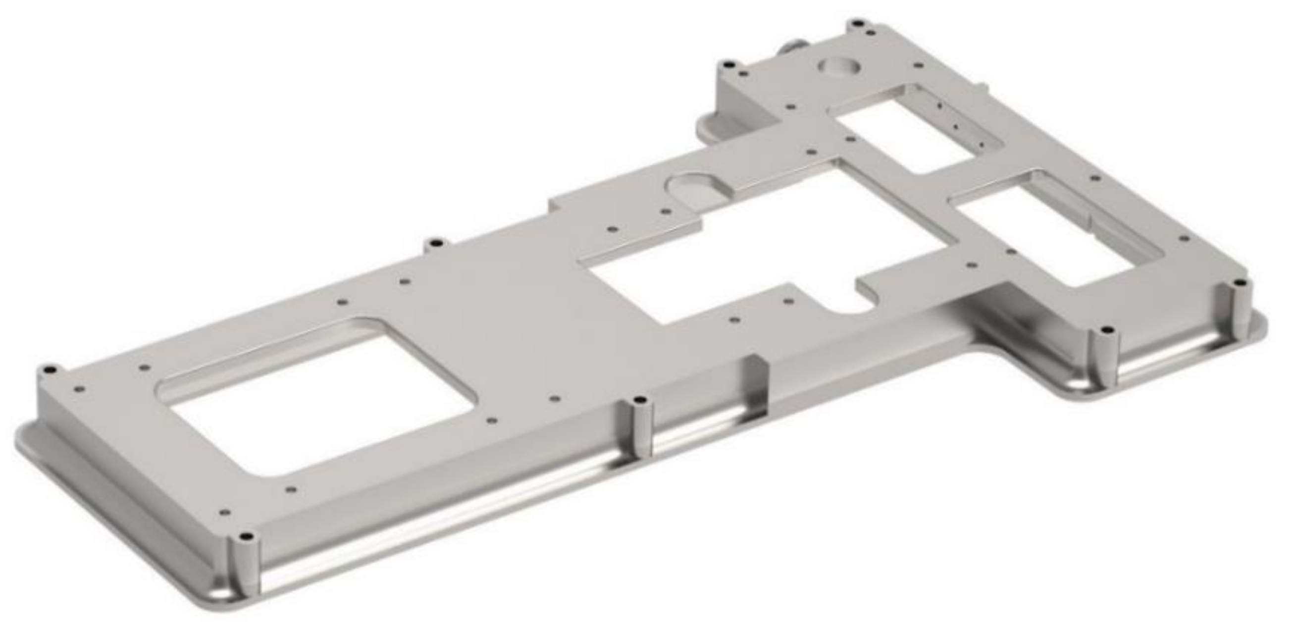
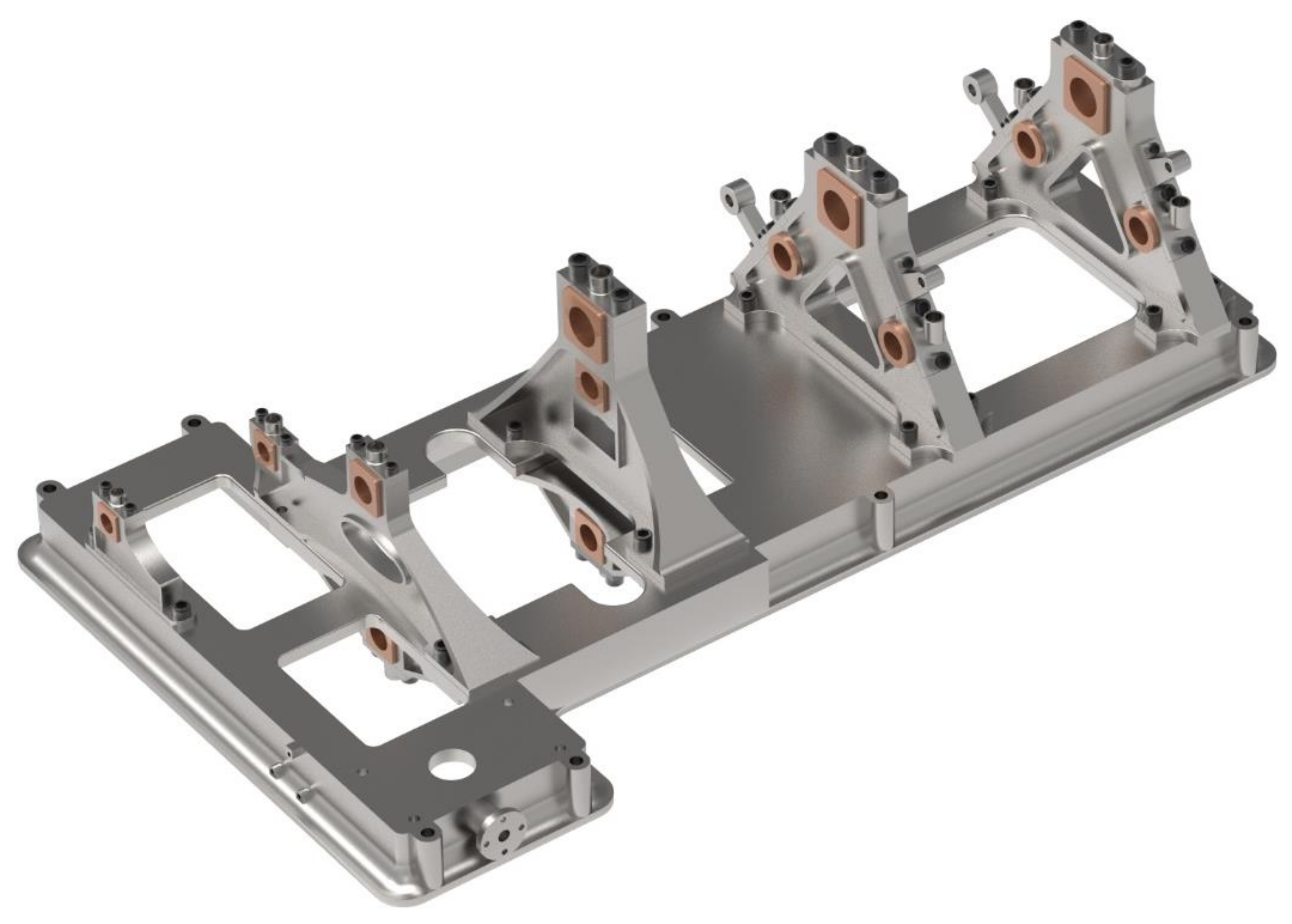
The function of the bedplate (
Figure 24) is to support the entire mechanism, by establishing a perfect base between the machine and location where the assembly will occur. For this purpose, the piece has a set of orifices on its perimeter to anchor itself to said location and reduces its weight, since it only has a thickness of 6 cm, thereby obviating the need for the block to be solid.
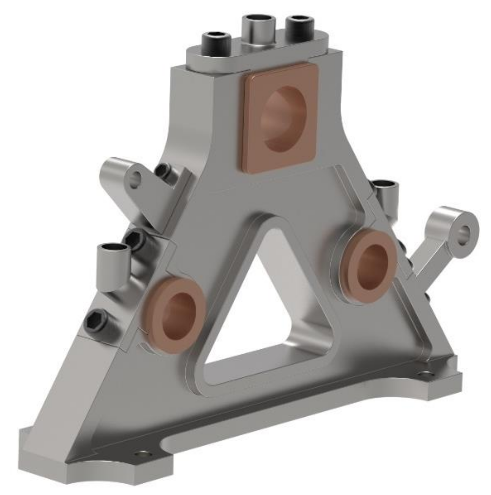
The bearing structures are one of the fundamental elements for the correct operation of the invention, since, although they are not a dynamic element, they ensure the correct position of all the elements. The bearings have small orifices that function as lubrication points.
Figure 25 shows one of the bearings, where the three orifices to house the shafts can be observed. All the other bearings are shown in the base assembly. Each bearing is different in shape, but the operation is basically the same, that is, to house the shafts, crankshaft, and gear train.
Finally,
Figure 26 shows the assembly of all the elements of the base, whereby each bearing structure is anchored to the bedplate by means of screws.
3.4. Mechanical Study of the Gear Train of the Assembly
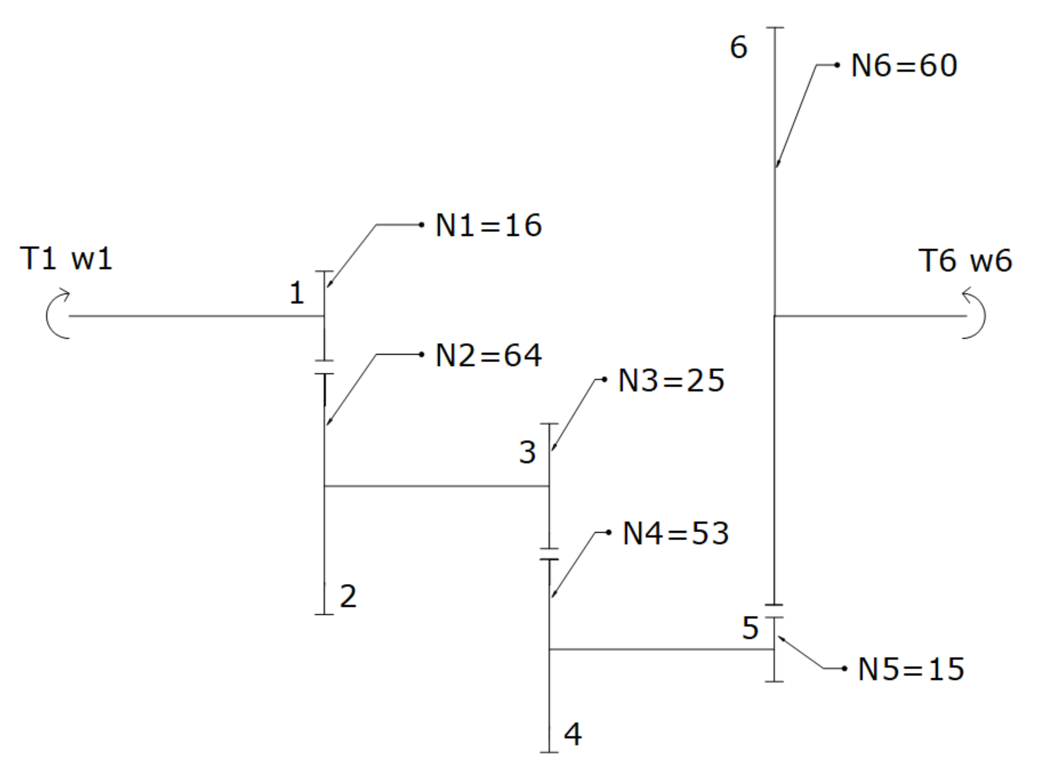
A brief mechanical study of the transmission train of the assembly is now carried out, in an effort to reveal the importance of implementing a gear train speed reducer and force multiplier. In
Figure 28, the diagram of the gear train is shown, whereby the odd-numbered wheels match the driving wheels, and the even-numbered wheels match the driven wheels. The rectilinear movement, generated by the steam engine, is transformed into a circular movement, thanks to the rod-and-crank mechanism connected, in turn, to gear shaft 1. The objective is to obtain the linear force generated by the steam in the piston, along with the knowledge on how it multiplies, in order to power the cylinders that produce the milling of the sugar cane.
From the equations that govern the behaviour of gear train and information on the number of teeth that each gear presents, the following transmission ratio (i) can be obtained:
Furthermore, it is known that: , where ω is the rotational speed (angular velocity), and N is the number of teeth on each gear.
Given the rotational speed of the mill and the power (P) of the steam engine (known data from the information collected), it is possible to define the rotational speed of the crankshaft (ω
1), its torque (T
1), and the force of the piston (F
piston).
In an ideal model with no losses, the power generated by the engine would be conserved throughout the machine. However, since it is a real model, a mechanical efficiency of 80% (
) has been assumed, which especially takes the interlocking losses into account. By applying this efficiency, the torque (T
6) generated in the shaft of the upper cylinder of the mill can be calculated.
Therefore, it is observed that the use of the gear train, with its corresponding transmission ratio, means that the machine was capable of multiplying its torque, by a factor of approximately 27, passing from 330.5 Nm at the crankshaft (T
1) to 8989 Nm (T
6) on the shaft of the upper cylinder of the mill. Once the torque is obtained in the latter shaft, the tangential force that is exerted on the surface of the upper cylinder of the mill can be calculated, given its diameter (0.508 m).
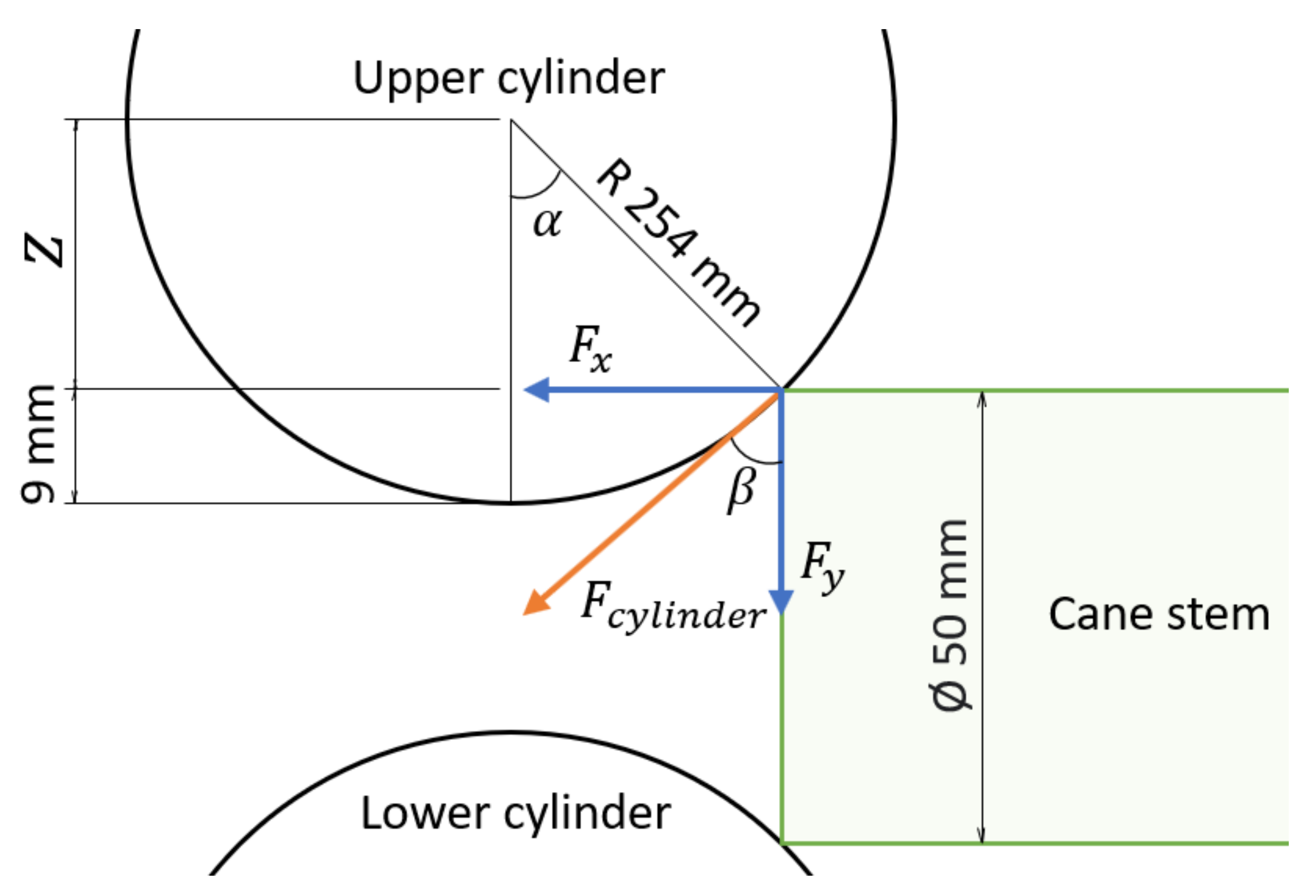
On the other hand, the maximum compression force, exerted by the cylinder on a sugarcane stem, occurs in its first contact with the mill cylinders, taking a 5 cm diameter cane stem as reference. Given the position of the cylinders, it is easy to analyse how the force is distributed on said stem (
Figure 29).
Therefore, using the schema in
Figure 29 as a reference, it is possible to calculate how the force, exerted by the surface of the cylinder, is directed on the stem of the sugar cane.
As can be observed in
Figure 29, the effective compression force exerted on the stem is F
y, while F
x would be the drag force in charge of attracting said stem into the mill.
Therefore, it is observed how the compression force (F
y), exerted on the sugarcane stem, is approximately 1 ton (951.70 Kg), since 1 N is equivalent to 0.1019 kg f. Furthermore, since the cylinders have parallel grooves on their surface, and due to their low angular velocity, it is ensured that the stem is dragged between the two cylinders without slipping. The stem is, thus, able to find the next pair of cylinders that are responsible for making a second pressing and ejecting said stem; hence, the combination of forces, shown in
Figure 29, is sufficient for both pressing and extracting the juice.
This study has been carried out for the ideal condition, where only one stem is pressed. The objective was to obtain the maximum force that the cylinders could exert, thanks to the transmission ratio of the gear train. However, in a real operating condition, more than one stem would be introduced through the cylinders simultaneously, reducing the force (pressure) they would exert on the stems. This force would be calculated by dividing the force obtained in the ideal condition by the number of stems introduced simultaneously.
Finally, if one wanted to increase the compression force on the stem, it would only be necessary to bring the surfaces of the cylinders closer to each other, for example, by bringing the shafts of the lower cylinders closer to that of the upper cylinder or increasing their diameter.


 ,
, 


