Article

Research on the Electromagnetic Conversion Method of Stator Current for Local Fault Detection of a Planetary Gearbox

1
School of Mechatronics and Vehicle Engineering, Chongqing Jiaotong University, Chongqing 400074, China
2
Department of Mechanical Engineering, University of Manitoba, Winnipeg, MB T3T 2N2, Canada
*
Author to whom correspondence should be addressed.
Machines 2021, 9(11), 277; https://doi.org/10.3390/machines9110277
Submission received: 8 October 2021 / Revised: 5 November 2021 / Accepted: 6 November 2021 / Published: 8 November 2021
(This article belongs to the Special Issue Advances in Bearing Modeling, Fault Diagnosis, RUL Prediction)

Abstract

:
Motor current signature analysis (MCSA) is a useful technique for planetary gear fault detection. Motor current signals have easier accessibility and are free from time-varying transfer path effects. If the fault symptoms in current signals are well understood, it will be more beneficial to develop effective current signal processing methods. Some researchers have developed mathematical models to study the characteristics of current signals. However, no one has considered the coupling of rotor eccentricity and gear failures, resulting in an inaccurate analysis of the current signals. This study considers the sun gear failure of a planetary gearbox and the eccentricity of the motor rotor. An improved induction motor model is proposed based on the magnetomotive force (MMF) to simulate the stator current. By analyzing the current, the modulation relationships of gearbox meshing frequency, fault frequency, power supply frequency, and gear rotating frequency are obtained. The proposed model is validated to some extent using experimental data.

1. Introduction

Planetary gears are widely used in the modern industry. The harsh working environment often leads to damages to gear parts. If the damage is not detected earlier, it may cause a large economic loss or catastrophe. Therefore, the condition monitoring and fault diagnosis of the planetary gearbox is very important for the safe and stable operation of the equipment [1].
Vibration analysis has been used to detect gear faults for a long time, but they need to install vibration sensors on a gearbox. The motor current signature analysis (MCSA) uses motor current for analysis without having to install extra sensors in a gearbox, which can effectively reduce maintenance and inspection costs.
Researchers have developed advanced signal processing methods that can use motor current signals for fault diagnosis. Toma [2] proposed a feedforward neural network to diagnose winding short-circuit faults of a three-phase induction motor with a wound rotor. The neural network model proposed by Leite [3] overcomes the common voltage imbalance, measurement noise and variable load in practice when diagnosing motor faults. difficulty. Touti et al. [4] proposed a current signal preprocessing technology to improve the sensitivity of gear-related frequencies. Singh et al. [5] use resampling technology (IAR) to diagnose gearbox faults in non-stationary conditions. Zhang et al. [6] propose an algorithm for detecting gear wear. In the current signals, the fundamental frequency of the power supply and its harmonics dominate signals. Furthermore, the fault symptoms are very weak in current signals, especially for early gear damages. Therefore, when using MCSA to diagnose gear failures, how to identify and extract weak signals becomes an important research topic.
In addition to the existing advanced signal processing methods, researchers tried to develop electromechanical dynamic models to identify fault symptoms in the motor current signals. Gligorijevic et al. [7] mentions that online detection is one of the effective means to avoid the deterioration of system faults. The non-invasiveness of current detection provides favorable conditions for online detection systems. In many actual industrial processes, process failures will leave a clear trend [8] in the monitored sensors, and the characteristics of the current that are easy to monitor can identify abnormalities in the process. Ottewill et al. [9] used the space vector model to simulate the stator current, and studies showed that planetary gearbox faults could be detected from the motor current. Capolino et al. [10] proposed a planetary gear dynamics model related to a wound rotor induction motor based on the equivalent circuit diagram of the rotor-end short-circuit induction motor. Feki et al. [11] proposed a mechatronic model using the Krone transform (based on the stator current of a motor) and explained the possibility of measuring the position and size of the spur gear defect through the stator current. Kia et al. [12] established a coupling model (integration of spur gear dynamic model and stator shafting reference Frame motor model) and studied the electromechanical system of a spur gearbox. Later, researchers developed the electromechanical coupling model based on the magnetic conduction network. Feki et al. [13] established a permeable network model (PNM) and a dynamic model of spur gears and proposed an iterative solution technique. Han et al. [1] established a lumped parameter torsion model of the motor-planetary gearbox-coupling system based on the magnetic equivalent circuit (MEC). An iterative numerical integration method was proposed to solve the MEC model. The lumped parameter model can perform qualitative analysis on the gear-motor coupling system, while the model based on the permeation network can perform quantitative analysis. However, the electromagnetic conversion relationship is hidden in the above model. If the electromagnetic conversion relationship of the motor can be extracted, it will be beneficial to understand the effect of the gearbox on the current signal.
The MMF method has a good effect on the analysis of the electromagnetic conversion relationship of the motor. A few people used the MMF method to build a stator current model to study planetary gearbox faults. This method expresses the magnetic permeability as a function of space and time and expands it with a Fourier series, which reduces the calculation complexity. Therefore, it is easier to calculate the permeability for a rotor with eccentricity than the above models. It seems feasible to use this method to study the coupling of rotor eccentricity and gear failures. Moreover, due to the time and space harmonics of the motor, many frequency sidebands exist in the stator current signals. If these sideband frequencies are not identified accurately, it will be hard to locate gear damage frequencies accurately. The MMF method is traditionally used for the calculation of the magnetic airgap field for rotor and stator slotting or static and dynamic eccentricity [14,15]. It was used in [16] to identify the effect of bearing fault-related load torque oscillations on the stator current, but it lacks the connection between mathematical model and experiment. Nandi et al. [17] used this method to study the stator current of the motor rotor under mixed eccentricity, extend this method to motors of any structure. Chen et al. [18] established the AM-FM model of the stator current of the planetary gearbox asynchronous motor using the MMF method, a new current signal processing method is proposed to improve the detection success rate. Blotd et al. [19] studied the effect of torque oscillation on the stator current of induction motors. It shows that time-frequency analysis is an effective tool for analyzing current. Kia et al. [20] presented a theoretical framework based on the torque oscillation caused by the unique torsional vibration in the gearbox. In the stator current model established by the MMF method, the dynamic response of the motor rotor’s speed and angle is very important.
In References [14,15,16,17,18,19,20], the authors used transient torque or steady-state torque to express the motor rotor speed and the potential magnetic angle between the motor stator and rotor. The use of transient and steady states to express speed and angle is simple and clear. However, the method lacks correlation with the physical parameters of the gearbox (such as gear meshing stiffness). Although the speed of rotor and rotation angle information can also be obtained using encoders, sometimes, it is inconvenient to install the sensor. This paper uses the lumped parameter model of the planetary gearbox to simulate the speed and angle information of the rotor, which can consider more realistic physical parameters.
The coupling effect of rotor eccentricity and gear failure was rarely considered in existing studies. Rotor eccentricity can be regarded as static or dynamic eccentricity. When an eccentric fault occurs in the rotor, the rotor no longer rotates around the center of the stator, resulting in an uneven air gap magnetic field, which affects the current induced by the rotor bar on the stator winding and changes the characteristics of the stator current. Due to the complex and changing operating environment, static eccentricity faults and dynamic eccentricity faults often exist at the same time. When the center of rotation is between the stator bore axis and the rotor axis, two types of eccentricity exist (mixed eccentricity) [21]. As shown in Figure 1, If the center of rotation is concentric with the axis of the rotor, but outside the axis of the stator hole, a static eccentricity occurs. The dynamic eccentricity occurs if the center of rotation is outside the rotor axis but concentric with the stator axis. Among them, O s O stands for static eccentricity, and O O r stands for dynamic eccentricity. The blank part between the stator and the rotor represents the air gap magnetic field of the motor, which is generally uniform.
Fault diagnosis methods can be divided into: model-based methods, signal-based methods, knowledge-based methods, hybrid methods, and active fault diagnosis methods. [22] In this paper, the electromechanical dynamics model is established based on the model method to study the motor current signal used for gear fault detection. The cou-pling effect of rotor eccentricity and gear failure is considered in this model. The planetary gearbox model reported in [23] is used directly. For a gear-motor coupling system, the stator current contains a complex of frequency components. It is hard to explain the generation mechanism of these frequency components. The MMF method can accurately model the electromagnetic conversion of a motor. It models the magenetic permeability as a function of time and space, which can be expressed by Fourier series. With Fourier series, it is very easy to analyze the frequency components and their corresponding sidebands. Overall, the MMF method can interpret these frequency components and their generation mechanism more accurately than other method such as the MEC method. Therefore, this article developed an improved flux model based on the method report in [24]. The speed and angle dynamic response results of the gear dynamic model is introduced into the stator current model to obtain the stator current signal under the coupling of two faults (rotor eccentricity and gear failure). Compared with existing magnetic flux methods, the proposed model can represent the coupling effect of two faults and will be more accurate to analyze the modulation of the meshing frequency, fault frequency, power supply frequency, and speed frequency in the stator current.

2. Motor Stator Current Modeling

In this section, two models will be developed to simulate the stator current in the motor-gear electromechanical system, as shown in Figure 2. The lumped parameter model is used to simulate the planetary gearbox system. This model is the same as the model created by Kahraman [23]. A MMF method is used to simulate the motor system. The main factors considered in the model include time-varying speed, angle fluctuation, eccentricity, and power harmonics.

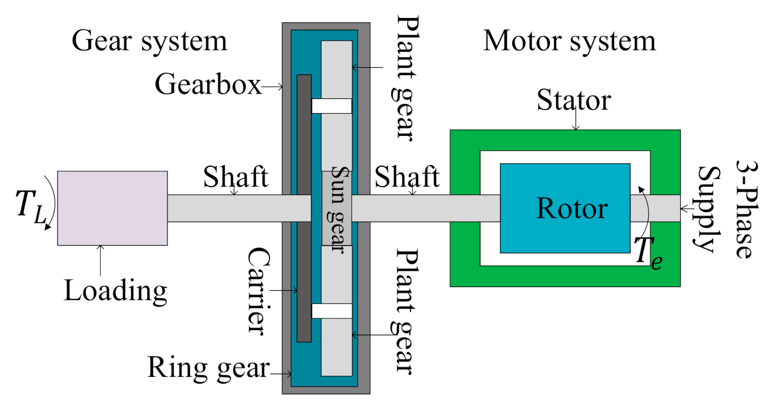
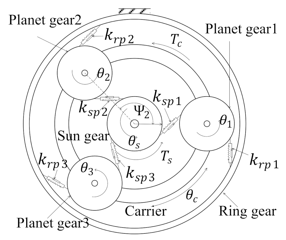
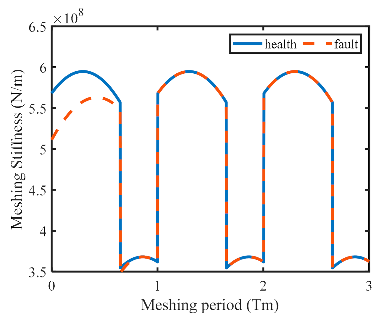
2.1. Planetary Gearbox Dynamic Model

A pure torsional dynamics model of the planetary gearbox is shown in Figure 3. Each component is treated as a rigid body. Moment of inertia is represented by J c , J s , J j j = 1 , 2 , 3 ; subscripts c , s , and j indicate the planet carrier, sun gear and the j t h planetary gear, respectively. The torsional angular displacement of each component is expressed as θ i i = c , s , j . The meshing stiffness of the sun gear and planetary gears, ring gear and planetary gears along the meshing line is represented by k s p j an k r p j , respectively. The equation of equilibrium of the planetary gearbox is obtained as [23]:
M q ¨ + C q ˙ + K t q = T .
where:
M = d i a g J c + N m p r c 2   J s   J 1     J 2   J 3 , q = θ c   θ s   θ p 1   θ p 2   θ p 3 T , T = T c   T e   0   0   0 T , C = ζ K t ¯ .
M ,   C , and K t represent the inertia matrix, damping matrix, and time-varying meshing stiffness matrix, respectively; T c represents the load torque, and T e means the electromagnetic torque; m p represents the mass of the planetary gear, and r c is the center distance between the sun gear and the planetary gear; damping is expressed by proportional damping, and the damping coefficient is ζ ; K t ¯ represents the average meshing stiffness matrix.
Figure 3. Planetary gearbox torsional model.
Machines 09 00277 g003

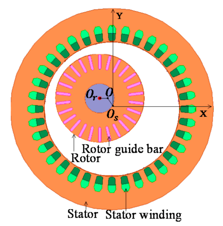
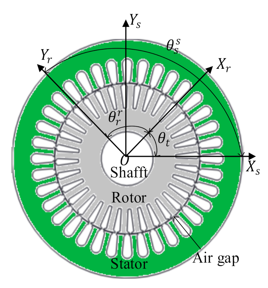
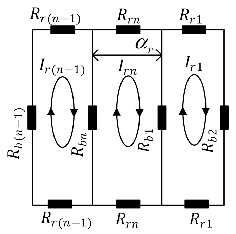
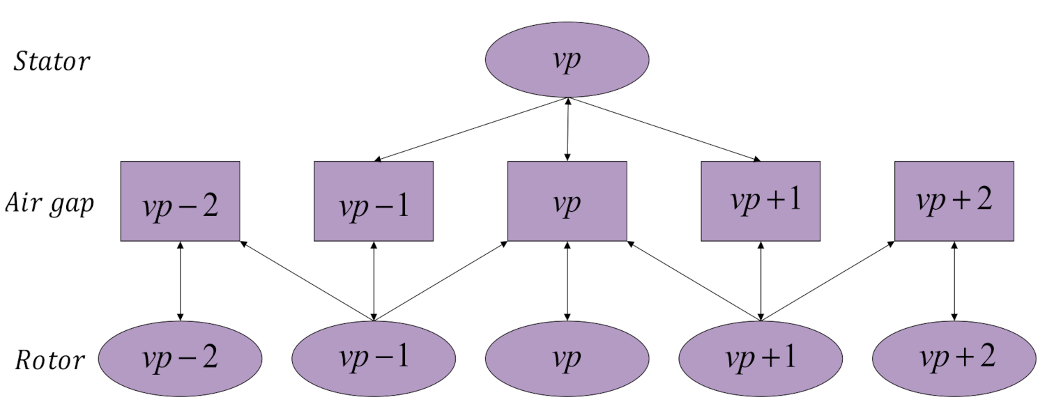
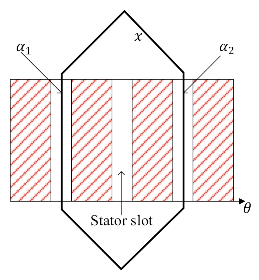
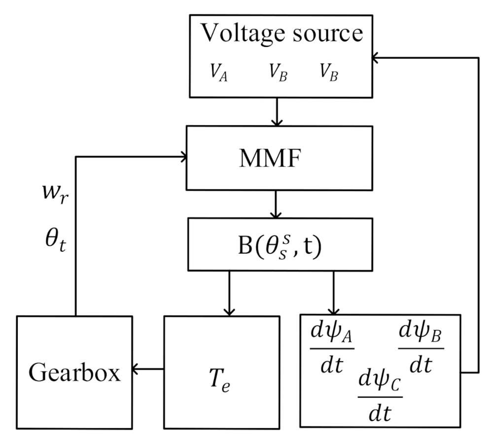
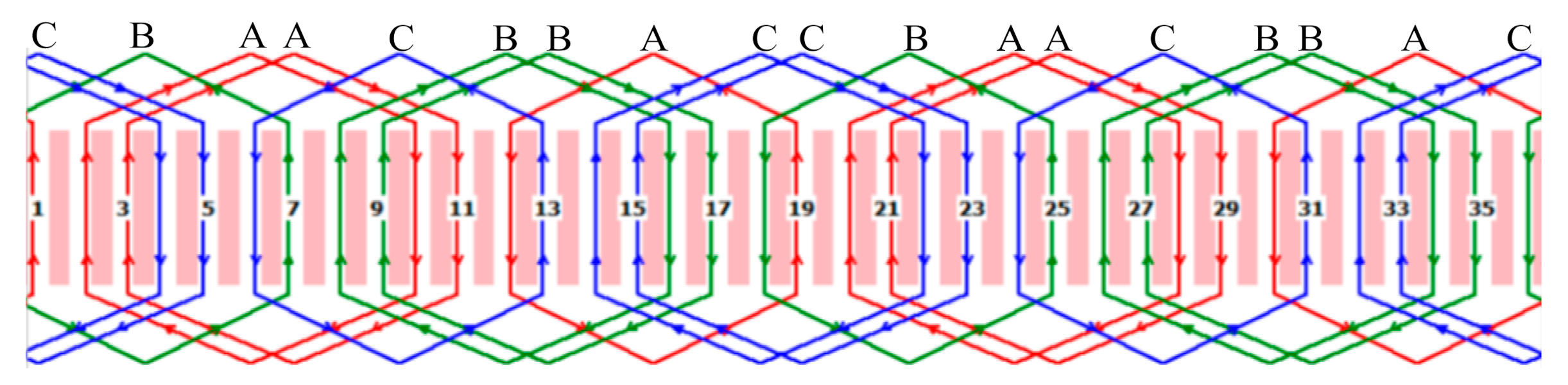
2.2. Stator Current Modeling

The MMF of the stator winding is generated by the current on the stator winding, and the current is generated by the voltage applied to the end of the three-phase stator winding. Assuming the symmetrical three-phase power supply is connected, the m t h (m = 1, 2, 3, corresponding to A, B, C phase) voltage can be expressed as
V m t = V s , k cos k w s t m 1 2 π / 3 ,
where V s , k is the peak value of the k t h harmonic of the stator winding phase current, and w s is the power angular frequency ( w s = 2 π f s ) . The MMF of the stator winding of each phase is synthesized, and the MMF of the stator winding produced by the harmonics of the k t h power supply is obtained as [25]:
F s s θ s s , t = F s , k μ k w v v cos k w s t v p θ s s , k = 1 , 3 , 5 , 7 , , v = 6 μ + 1 ,   μ = 0 , ± 1 , ± 2 , ± 3 , ,
where F s , k is the amplitude of the harmonic MMF, k w v is the v t h winding coefficient of the stator winding, and the specific calculation methods of k w v and F s , k can be found in [25], v is the number of spatial harmonics of the harmonic MMF, p is the number of pole pairs of the motor, and θ s s represents the mechanical angle of the stator in the stator coordinate system.
Due to the influence of stator and rotor slotting and iron core magnetic saturation, the air gap permeability is varying. The carter coefficients K c s and K c r are introduced for the effect of stator and rotor slotting, and the saturation coefficient K s is introduced for the effect of iron core saturation. The expression of the air gap permeability of the eccentric mixing rotor is as Equation (4) [26].
λ θ s s , t = Λ 0 + Λ 0 e s cos θ s s + Λ 0 e d cos θ s s θ t , Λ 0 = μ 0 K c s K c r K s δ .
In Equation (4), μ 0 is the vacuum permeability, δ means the average air gap length of the motor, e s represents the static eccentricity, e d means the dynamic eccentricity, and θ t is shown in Figure 4. The stator flux density is obtained by Formulas (2) and (3), as shown in Equation (5).
B s s θ s s , t = F s s θ s s , t λ θ s s , t = B s , k , μ cos k w s t v p θ s s + ( B s , k , μ e s 2 ) cos k w s t v p ± 1 θ s s + B s , k , μ e d 2 cos k w s t v p ± 1 θ s s ± θ t B s , k , μ = F s , k , μ Λ 0 μ k w v v .
Convert the stator flux density B s s θ s s , t to the rotor coordinate system, and calculate the size of the flux linkage generated on the rotor. The conversion relationship between the stator coordinate system and the rotor coordinate system is shown in Figure 4 where θ t represents the angular difference between the stator and the rotor when the rotor speed fluctuates, X s Y s represents the stator coordinate system, and X r Y r represents the rotor coordinate system.
The mathematical expression for the conversion of the stator and rotor coordinate system is θ s s = θ r r + θ t ; θ r r represents the mechanical angle of the rotor in the rotor coordinate system. The transformed stator flux density in the rotor coordinate system is shown in Equation (6).
B r s θ r r , t = B s , k , μ cos k w s t v p θ r r v p θ t + B s , k , μ e s 2 cos k w s t v p ± 1 θ r r v p ± 1 θ t + B s , k , μ e d 2 cos k w s t v p ± 1 θ r r v p θ t .
The stator flux density in the rotor produces flux linkage in the rotor windings, as shown in Figure 5. Here, a r represents the mechanical slot pitch angle of the rotor ( a r = 2 π / N r ) and N r represents the number of rotor slots. The symbols R r   and   R b represent the resistance of the rotor end ring and the bar resistance, respectively.
Calculate the flux linkage in the n t h winding of the rotor, as shown in Equation (7). In Equation (7), l e f represents the axial length of the motor and D s represents the inner circle diameter of the stator.
ψ r , n s = n 1.5 a r n 0.5 a r l e f D s B r s θ r r , t d θ r r = ψ r , n , o , v p s cos k w s t v p n 1 a r v p θ t + ψ r , n , s , v p ± 1 s cos ( k w s t v p ± 1 n 1 a r + θ t + ψ r , n , d , v p ± 1 s cos k w s t v p ± 1 n 1 a r v p θ t ψ r , n , o , v p s = 2 l e f D s B s , k , μ v p sin v p a r 2 ψ r , n , s , v p ± 1 s = l e f D s B s , k , μ e s v p ± 1 sin v p ± 1 a r 2 ψ r , n , d , v p ± 1 s = l e f D s B s , k , μ e d v p ± 1 sin v p ± 1 a r 2 .
Calculate the current of the n t h winding of the rotor in Figure 5 as Equation (8). In Equation (8) R n r represents the resistance of the n t h rotor winding, R n r = R b + N r 2 R r / 2 π 2 p 2 ; k s v represents the rotor skew coefficient [20].
I r , n t = d ψ r , n s d t k s v R n r = I r , n , o , v p s sin k w s t v p θ t v p n 1 a r + I r , n , s , v p ± 1 s sin ( k w s t v p ± 1 n 1 a r + θ t + I r , n , d , v p ± 1 s sin k w s t v p ± 1 n 1 a r v p θ t I r , n , o , v p s = ψ r , n , o , v p s k s v R n r k w s v p w r I r , n , s , v p ± 1 s = ψ r , n , s , v p ± 1 s k s v R n r k w s v p ± 1 w r I r , n , d , v p ± 1 s = ψ r , n , d , v p ± 1 s k s v R n r   k w s v p w r .
The MMF generated by the induced current of the n t h winding of the rotor is
F r s θ r r , t = I r , n t N n r θ r r
where N n r θ r r represents the winding function of the n t h winding of the rotor, and its expression is [27]:
N n r θ r r = λ = 1 2 sin λ π N r cos λ θ r r n 1 a r λ π .
After calculation, the total rotor winding MMF harmonics are as shown in Equation (11):
F r s θ r r , t = n = 1 N r   { F r , n , o , v p , λ s sin k w s t v p ± λ n 1 a r v p θ t ± λ θ r r + F r , n , s , v p ± 1 , λ s [ sin ( k w s t v p ± 1 + λ n 1 a r v p ± 1 θ t + λ θ r r + sin ( k w s t v p ± 1 λ n 1 a r v p ± 1 θ t λ θ r r ) ] + F r , n , d , v p ± 1 , λ s [ sin k w s t v p ± 1 + λ n 1 a r v p θ t + λ θ r r + sin k w s t v p ± 1 λ n 1 a r v p θ t λ θ r r ] } F r , n , o , v p , λ s = λ = 1 I r , n , o , v p s sin λ π N r λ π k w s v p w r F r , n , s , v p ± 1 , λ s = λ = 1 I r , n , s , v p ± 1 s sin λ π N r λ π k w s v p ± 1 w r F r , n , d , v p ± 1 , λ s = λ = 1 I r , n , d , v p ± 1 s sin λ π N r λ π k w s v p w r .
Then, multiply Equation (11) with the air gap permeability λ θ s s , t to obtain the rotor flux density. The rotor flux density will form a turn chain with the stator winding, thereby generating an induced electromotive force on the stator winding. However, not all the rotor flux density harmonics can produce induced electromotive force in the stator windings, as shown in Figure 6. A motor with a pole pair number p generates v p or v p ± 1 magnetic fields in the air gap. Due to the mismatch of the number of pole pairs, the v p ± 1 magnetic field generated by the rotor cannot induce the back electromotive force on the stator side.
Take the motor pole pair number p = 2 used in this article as an example. Considering the fundamental wave ( v = 1 ), the rotor flux density harmonics that can generate induced electromotive force in the stator windings are shown in Equation (12).
B s r θ s s , t = N r F r , n , o , 2 , 2 s Λ 0 sin k w s t 2 θ s s + N r F r , n , s , 1 , 1 s Λ 0 e s sin k w s t 2 θ s s + N r F r , n , s , 3 , 3 s Λ 0 e s sin k w s t 2 θ s s + N r F r , n , d , 1 , 1 s Λ 0 e d sin k w s t 2 θ s s + N r F r , n , d , 3 , 3 s Λ 0 e d sin k w s t 2 θ s s + N r F r , n , d , 1 , 1 s Λ 0 e s sin k w s t θ t 2 θ s s + N r F r , n , d , 3 , 3 s Λ 0 e s sin k w s t + θ t 2 θ s s + N r F r , n , s , 1 , 1 n Λ 0 e d sin k w s t + θ t 2 θ s s + N r F r , n , s , 3 , 3 n Λ 0 e d sin k w s t θ t 2 θ s s .
It can be seen from Equations (5) and (12) that when considering the speed fluctuation of the planetary gearbox and the rotor eccentricity, the total air gap flux density in the motor is
B θ s s , t = B s s θ s s , t + B s r θ s s , t .
According to the virtual displacement method, the general formula of the electromagnetic torque of the motor can be derived [28]:
T e = p W m δ s r ,
where δ s r represents the motor power angle and W m is the magnetic energy in the air gap magnetic field, which can be expressed as
W m = 0 v B θ s s , t 2 2 μ 0 d v = D s l e f δ 4 μ 0 0 2 π B θ s s , t 2 d θ s s .
The flux linkage produced by the air gap flux density B θ s s , t at the x t h coil of the m t h phase is
ψ x t = α 1 α 2 l e f D s B θ s s , t d θ s s ,
where α 1 ,   α 2 represents the mechanical angle of the effective side of the x t h coil in the inner circle of the stator, as shown in Figure 7. Add the flux linkages of all coils of phase m to get the total flux linkage ψ m t .
According to the stator loop voltage equation [28], the m t h phase stator current is
I m t = V m t d ψ m t d t R s ,
where V m t represents the m t h voltage of the stator winding, and R s represents the m t h stator winding resistance.

3. Stator Current Simulation Analysis

In this section, the model in Section 2 is used to simulate the motor stator current. The entire system is simulated using Matlab. The planetary gear dynamics equations are solved by the Runge–Kutta method. Each response of gear dynamics is submitted to the MMF equation to obtain the current, as shown in Figure 8. The physical parameters of the gearbox are shown in Table 1. The planetary gearbox consists of one sun gear, one fixed ring gear and three planetary gears. The planetary gears are evenly distributed around the sun gear.
The time-varying meshing stiffness is evaluated using the potential energy method [29]. When the single and double teeth alternately mesh, or the sun gear has a localized tooth defect, the gear stiffness will change suddenly. Figure 9 shows the change of the sun gear stiffness with time in one cycle. The meshing frequency is f m = f r Z r i n g / ( 1 + Z r i n g / Z s u n ) Hz , where f r is the rotation frequency of the sun gear. The failure frequency of localized tooth defect of the sun gear is f w = N f m / Z s u n Hz .
The motor selected for the simulation is a small three-phase asynchronous motor. The motor parameters are given in Table 2.
The size of each phase of the motor flux is related to the winding form. In order to accurately calculate Equation (16), the space angle of each phase winding inside the stator needs to be accurately given. The Y100L2-4 motor adopts single-layer cross winding as shown in Figure 10. The A-phase coil group is represented by red; the B-phase coil group is represented by green, and the C-phase coil group is represented by blue. Each phase coil group is composed of 6 coils, and each coil occupies two slots of the stator. Taking the left side of the coil as the upper side and the right side as the lower side, and calculate the mechanical angle of each phase winding side based on slot 1, as shown in Table 3.

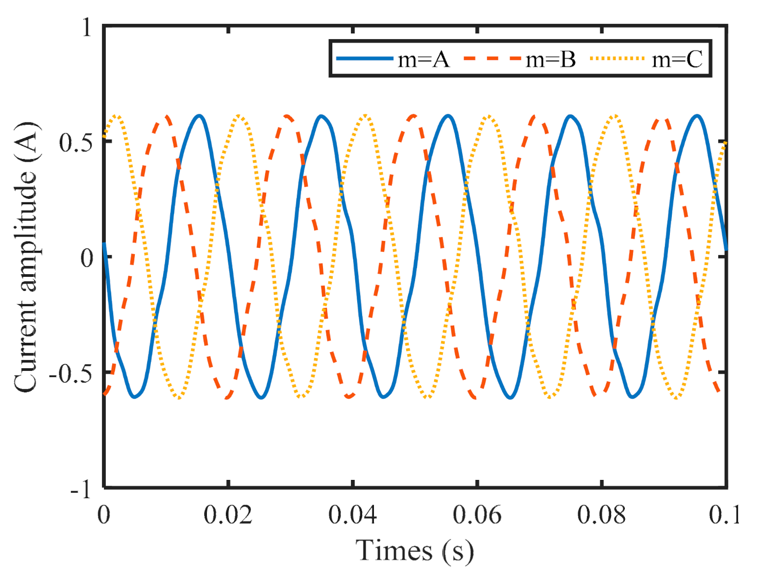
3.1. Stator Three-Phase Current

The MMF model of Y100L2-4 is established with the above-mentioned motor parameters, and common harmonic orders (k = 1, 3, 5, 7) are introduced into the simulated input voltage. The simulation obtains the stator current under the gearbox-motor coupling, as shown in Figure 11. The current information contained in each phase of the symmetrical three-phase winding is the same but is 120° behind in phase. Therefore, the article will only analyze the phase A current to get the gear-related information in the current signal.
In order to analyze the influence of the mixed eccentricity on the gear signal in the current, the current signals with and without eccentricity were simulated. In the case of eccentricity, set dynamic eccentricity e d = 0.3 , static eccentricity e s = 0.1 , and in the case of no eccentricity e d = e s = 0 . The obtained current curve is shown in Figure 12. Figure 12a shows the signal with or without eccentricity in the time domain. In the time domain, the difference between the two is very small, and only the current without eccentricity at the peak is slightly smaller than the current with eccentricity. Their frequency domain signals are shown in Figure 12b. It should be noted that the power frequency is the main factor in the current signal, while the frequency related to the gear is relatively small. In order to suppress the power frequency and its harmonics and enhance the frequency related to the gear, this paper selects the spectrum to analyze the current signal. When there is no eccentricity, the current signal contains the fundamental frequency f s and its harmonics such as 3 f s , 5 f s , 7 f s . Due to the electromechanical coupling effect and the gear-related frequency is modulated by the power supply frequency, the modulated frequency is: f m ± k f s ( k = 1 , 3 , 5 , 7 ). When there is eccentricity, the speed frequency ( f r ) will also be modulated by the power frequency and its harmonics due to the eccentricity effect. The modulated frequency is: k f s ± f r ( k = 1 , 3 , 5 , 7 ) . At the same time, the information related to the gear will also be modulated by frequency conversion. The obvious frequencies are f m ± f s ± f r and f m ± 3 f s ± f r .

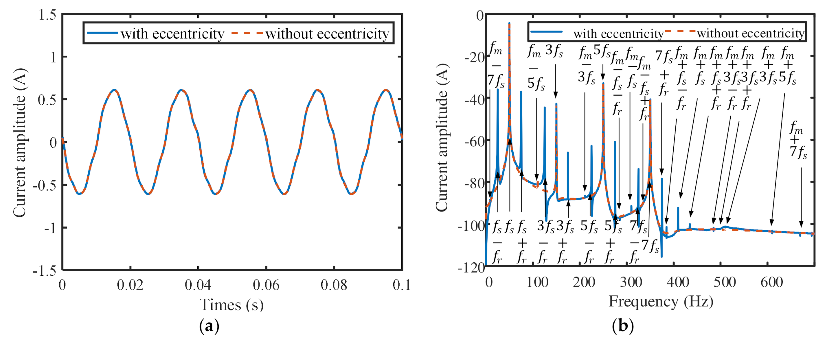
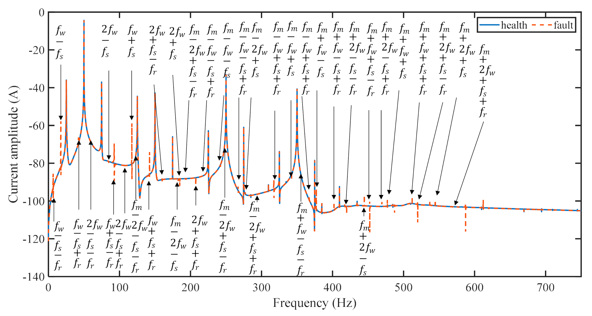
3.2. Stator Winding Current for Sun Gear Failure

Considering the tooth chipping of the sun gear, the stator current of the induction motor is calculated by the MMF model. And the current spectrum shown in Figure 13 is obtained. As a comparison, the graph also shows a fault-free current spectrum. It can be seen that regardless of whether the fault is considered, the main frequency components in the stator current are the power frequency f s and its harmonics ( 3 f s , 5 f s , 7 f s ). The sun gear’s faulty tooth meshes with all planetary gears (in this study, the number of planets is N = 3), resulting in a fault frequency, f w = 3 f m / Z s u n   H z and its harmonics 2 f w . In the spectrum related to the sun gear defect, the power supply frequency fs and fr are also found due to the electromechanical coupling effect and the eccentric effect. Therefore, the fault characteristic frequency of the solar fragmentation defect is summarized as i f m + j f w ± f s ± f r i = 0 , 1   j = 1 , 2 , .

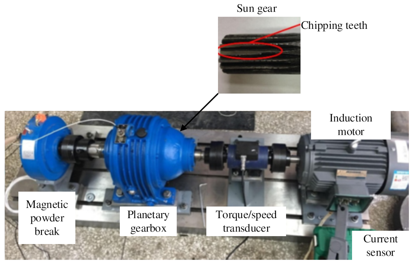
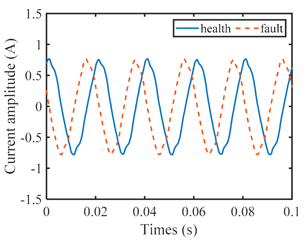
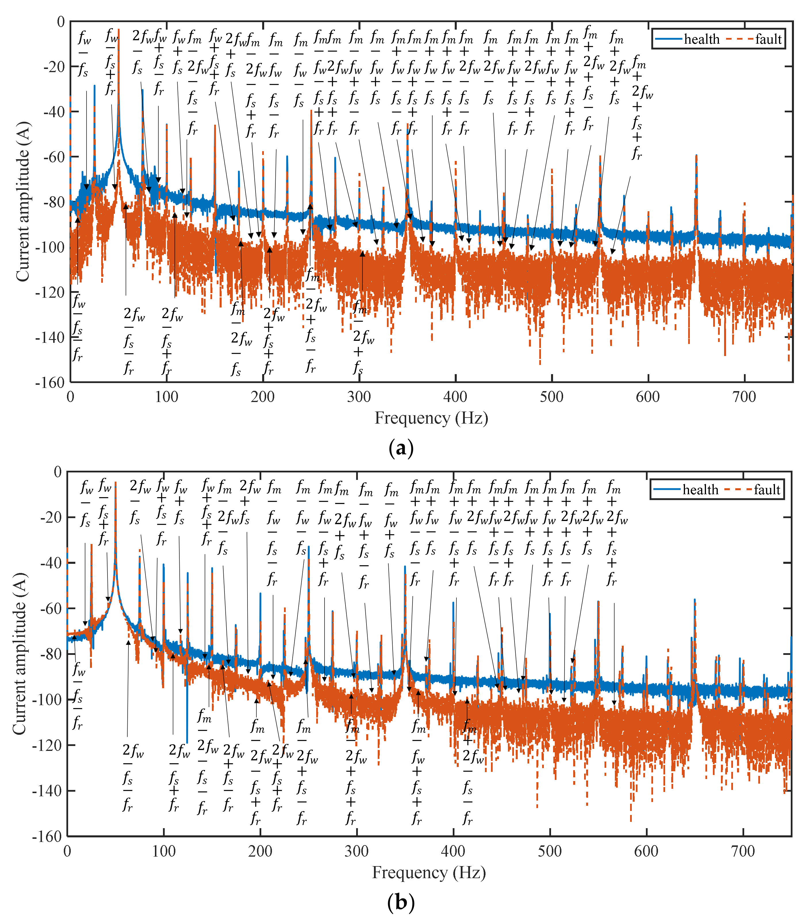
4. Experimental Validation

In this section, experiments are used to test the accuracy of the proposed model. As shown in Figure 14, the test rig consists of a three-phase asynchronous induction motor (Y100L2-4), a 2K-H planetary gearbox, and a magnetic powder brake (maximum torque 50 N·m). A current sensor (FLUKE 80i-110s) is used to measure the instantaneous current after passing through the stator winding. A defect is manually created on the sun gear by removing a part of the tooth. The number of gear teeth and the gear module are given in Table 1.
The speed of the motor is set as f r = 25   Hz . The gear meshing frequency and characteristic fault frequencies are f m = 359.75 and f w = 67.44 , respectively. Figure 15 shows the measured time domain signal of the stator current. In the time domain, almost no-fault symptoms can be seen.
Figure 16 shows the stator current spectrum when the sun gear is healthy or the sun gear tooth is defective, measured under experimental conditions. The current model established in terms of frequency content. The working conditions of Figure 16a,b are torque 0 N·m and 10.5 N·m, respectively. Similar to the simulation results, spectra under the two working conditions are respectively given in order to confirm the robustness of the measurement and the main component in the current spectrum is the power supply frequency and its harmonics ( f s , 3 f s , 5 f s ). It can be seen from Figure 16a,b that the influence of the sun gear failure on the stator current is more obvious in the frequency domain. Some characteristic frequencies can be found in the frequency domain, such as f w ± f s and f m ± f w ± f s , which are in good agreement with the results of other researchers [6]. In addition, when the motor rotor is eccentric, the fault characteristic frequency can be found in the test spectrum, such as f s ± f r , which indicates that the motor system has an eccentric fault [10,11]. Due to electromechanical coupling, if the planetary gear is not damaged, but the motor system has an eccentric fault, the characteristic frequencies are f m ± f s ± f r and f m ± f s . If the sun gear fails and the motor is eccentric, the characteristic frequencies are f w ± f s ± f r , f m ± f w ± f s ± f r and f w ± f s . These frequencies are very consistent with the results generated by the mathematical model in Section 3, which verifies our mathematical model to some extent. Therefore, the results of this study can give a more accurate fault-related frequency of the sun gear tooth defect when the motor rotor is eccentric.

5. Conclusions

In this study, a torsional dynamic model of the planetary gear system is combined with an MMF motor model to study the electromechanical coupling effect of the motor-gear system. The characteristics of stator currents coupled with different internal factors such as time-varying gear meshing stiffness and rotor eccentricity are studied. The fundamental frequency of the current and the gear speed can be found in the proposed stator current model. The modulation frequency of meshing frequency, sun gear failure frequency, rotor speed frequency, and power supply frequency are observed, which reveals the motor-gear coupling effect of the system based on the MMF motor model. Besides, the motor eccentric effect has a significant influence on the diagnosis of sun gear faults. If the eccentricity of the motor is not considered, the rotation frequency of the motor may be incorrectly diagnosed as the failure frequency of the sun gear. The experimental tests validate the proposed model to some degree. Still, there are many frequency components not predicted by this mathematical model. It will be further improved by considering the transmission error and friction.
In addition, uncertainties are not considered in the proposed method. They should be considered for the simulations to match real measurements [30]. In the future, we will further improve our model by considering uncertainties such as measurement noise, structured and unstructured uncertainties. The comparison between our proposed method and the key graph will also be one of the future works.

Author Contributions

X.X. agrees with the content of the article and is responsible for the authenticity and reliability of the resulting article. G.L. is responsible for the writing and revision of the paper. X.L. is responsible for the structure of the paper, the acquisition of data, the polishing of the content of the article, and the submission of the article. All authors have read and agreed to the published version of the manuscript.

Funding

This research was funded by the Foundation of National Natural Science of China (No. 51975078) and the Scientific Research Key Fund of Chongqing Municipal Education Commission (No. KJZD-K202000703).

Acknowledgments

Many thanks to Qinkai Han at the Tsinghua University (THU) for sharing their experimental dataset to validate our model.

Conflicts of Interest

The authors declare no conflict of interest.

References

  1. Han, Q.; Wang, T.; Ding, Z.; Xu, X.; Chu, F. Magnetic Equivalent Modeling of Stator Currents for Localized Fault Detection of Planetary Gearboxes Coupled to Electric Motors. IEEE Trans. Ind. Electron. 2020, 68, 2575–2586. [Google Scholar] [CrossRef]
  2. Toma, S.; Capocchi, L.; Capolino, G.A. Wound-Rotor Induction Generator Inter-Turn Short-Circuits Diagnosis Using a New Digital Neural Network. IEEE Trans. Ind. Electron. 2013, 60, 4043–4052. [Google Scholar] [CrossRef] [Green Version]
  3. Leite, D.F.; Hell, M.B.; Costa, P.; Gomide, F. Real-Time Fault Diagnosis of Nonlinear Systems. Nonlinear Anal. Theory Methods Appl. 2009, 71, e2665–e2673. [Google Scholar] [CrossRef]
  4. Touti, W.; Salah, M.; Bacha, K.; Amirat, Y.; Chaari, A.; Benbouzid, M. An Improved Electromechanical Spectral Signature for Monitoring Gear-Based Systems Driven by an Induction Machine. Appl. Acoust. 2018, 141, 198–207. [Google Scholar] [CrossRef]
  5. Singh, A.; Parey, A. Gearbox Fault Diagnosis under Fluctuating Load Conditions with Independent Angular Re-Sampling Technique, Continuous Wavelet Transform and Multilayer Perceptron Neural Network. IET Sci. Meas. Technol. 2017, 11, 220–225. [Google Scholar] [CrossRef]
  6. Zhang, R.; Gu, F.; Mansaf, H.; Wang, T.; Ball, A.D. Gear Wear Monitoring by Modulation Signal Bispectrum Based on Motor Current Signal Analysis. Mech. Syst. Signal Process. 2017, 94, 202–213. [Google Scholar] [CrossRef]
  7. Gligorijevic, J.; Gajic, D.; Brkovic, A.; Savic-Gajic, I.; Gennaro, S.D. Online Condition Monitoring of Bearings to Support Total Productive Maintenance in the Packaging Materials Industry. Sensors 2016, 16, 316. [Google Scholar] [CrossRef] [Green Version]
  8. Gao, Z.; Cecati, C.; Ding, S.X. A Survey of Fault Diagnosis and Fault-Tolerant Techniques—Part II: Fault Diagnosis With Knowledge-Based and Hybrid/Active Approaches. IEEE Trans. Ind. Electron. 2015, 62, 3768–3774. [Google Scholar] [CrossRef]
  9. Ottewill, J.R.; Ruszczyk, A.; Broda, D. Monitoring Tooth Profile Faults in Epicyclic Gearboxes Using Synchronously Averaged Motor Currents: Mathematical Modeling and Experimental Validation. Mech. Syst. Signal Process. 2017, 84, 78–99. [Google Scholar] [CrossRef]
  10. Capolino, G.A.; Far, Z.D.; Henao, H. Modeling and Simulation of Planetary Gearbox Effects on a Wound Rotor Induction Machine. In Proceedings of the IEEE International Symposium on Industrial Electronics (ISIE), Hangzhou, China, 28–31 May 2012. [Google Scholar]
  11. Feki, N.; Clerc, G.; Velex, P. An Integrated Electro-Mechanical Model of Motor-Gear Units-Applications to Tooth Fault Detection by Electric Measurements. Mech. Syst. Signal Process. 2012, 29, 377–390. [Google Scholar] [CrossRef]
  12. Kia, S.H.; Henao, H.; Capolino, G.A. A Modeling Approach for Gearbox Monitoring Using Stator Current Signature in Induction Machines. In Proceedings of the Industry Applications Society Annual Meeting, IAS’08, Edmonton, AB, Canada, 5–9 October 2008. [Google Scholar]
  13. Feki, N.; Clerc, G.; Velex, P. Gear and Motor Fault Modelling and Detection Based on Motor Current Analysis. Electr. Power Syst. Res. 2013, 95, 28–37. [Google Scholar] [CrossRef]
  14. Cameron, J.R.; Thomson, W.T.; Dow, A.B. Vibration and Current Monitoring for Detecting Airgap Eccentricity in Large Induction Motors. IEE Proc. B Electr. Power Appl. 1986, 133, 155–163. [Google Scholar] [CrossRef]
  15. Dorrell, D.G.; Thomson, W.T.; Roach, S. Analysis of Airgap Flux, Current, and Vibration Signals as a Function of the Combination of Static and Dynamic Airgap Eccentricity in 3-Phase Induction Motors. IEEE Trans. Ind. Appl. 1995, 1, 24–34. [Google Scholar]
  16. Schoen, R.R.; Habetler, T.G.; Kamran, F.; Bartfield, R.G. Motor Bearing Damage Detection Using Stator Current Monitoring. IEEE Trans. Ind. Appl. 1995, 31, 1274–1279. [Google Scholar] [CrossRef]
  17. Nandi, S.; Ilamparithi, T.C.; Lee, S.B.; Hyun, D. Detection of Eccentricity Faults in Induction Machines Based on Nameplate Parameters. IEEE Trans. Ind. Electron. 2011, 58, 1673–1683. [Google Scholar] [CrossRef]
  18. Chen, X.; Feng, Z. Time-Frequency Space Vector Modulus Analysis of Motor Current for Planetary Gearbox Fault Diagnosis under Variable Speed Conditions. Mech. Syst. Signal Process. 2019, 121, 636–654. [Google Scholar] [CrossRef]
  19. Blodt, M.; Faucher, J.; Dagues, B.; Chabert, M. Mechanical Load Fault Detection in Induction Motors by Stator Current Time-Frequency Analysis. In Proceedings of the IEEE International Conference on Electric Machines & Drives, San Antonio, TX, USA, 15–18 May 2005. [Google Scholar]
  20. Kia, S.H.; Henao, H.; Capolino, G.A. Analytical and Experimental Study of Gearbox Mechanical Effect on the Induction Machine Stator Current Signature. IEEE Trans. Ind. Appl. 2009, 45, 1405–1415. [Google Scholar] [CrossRef]
  21. He, Y.-L.; Deng, W.-Q.; Tang, G.-J.; Sheng, X.-L.; Wan, S.-T. Impact of Different Static Air-Gap Eccentricity Forms on Rotor UMP of Turbogenerator. Math. Probl. Eng. 2016, 2016, 5284815. [Google Scholar] [CrossRef] [Green Version]
  22. Gao, Z.; Cecati, C.; Ding, S.X. A Survey of Fault Diagnosis and Fault-Tolerant Techniques—Part I: Fault Diagnosis With Model-Based and Signal-Based Approaches. IEEE Trans. Ind. Electron. 2015, 62, 3757–3767. [Google Scholar] [CrossRef] [Green Version]
  23. Kahraman, A. Natural Modes of Planetary Gear Trains. J. Sound Vib. 1994, 173, 125–130. [Google Scholar] [CrossRef]
  24. Balan, A. Theoretical and Experimental Investigations on Radial Electromagnetic Forces in Relation to Vibration Problems of Induction Machines. Ph.D. Thesis, The University of Saskatchewan, Saskatoon, SK, Canada, 1997. [Google Scholar]
  25. Lipo, T.A. Introduction to AC Machine Design; Wiley-IEEE Press: Hoboken, NJ, USA, 2004. [Google Scholar]
  26. Bao, X.; Cheng, Z.; Wang, H. Monitoring Magnetic Field of Stator Yoke to Detect Eccentricity Fault in Induction Motor. In Proceedings of the Industrial Electronics & Applications, Kota Kinabalu, Malaysia, 20–22 November 2016. [Google Scholar]
  27. Joksimovic, G.; Djurovic, M.; Penman, J. Cage Rotor MMF: Winding Function Approach. Power Eng. Rev. IEEE 2001, 21, 64–66. [Google Scholar] [CrossRef]
  28. IEEE. Electric Machinery; Institute of Electrical and Electronic Engineers: Minneapolis, MN, USA, 1995. [Google Scholar]
  29. Liang, X.; Zuo, M.J.; Hoseini, M.R. Vibration Signal Modeling of a Planetary Gear Set for Tooth Crack Detection. Eng. Fail. Anal. 2015, 48, 185–200. [Google Scholar] [CrossRef]
  30. Djeziri, M.A.; Nguyen, L.; Benmoussa, S.; Msirdi, N. Fault Prognosis Based on Physical and Stochastic Models. In Proceedings of the Control Conference, Seattle, WA, USA, 26–28 July 2017. [Google Scholar]
Figure 1. Mixing eccentricity.
Machines 09 00277 g001
Figure 2. Motor-gear electromechanical system.
Machines 09 00277 g002
Figure 4. Coordinate system conversion.
Machines 09 00277 g004
Figure 5. Diagram of single-turn squirrel cage rotor winding.
Machines 09 00277 g005
Figure 6. Motor magnetic field harmonics.
Machines 09 00277 g006
Figure 7. Mechanical angle of the stator winding coil.
Machines 09 00277 g007
Figure 8. Model structure for Matlab coding.
Machines 09 00277 g008
Figure 9. Time-varying gear meshing stiffness of sun-planet.
Machines 09 00277 g009
Figure 10. Schematic diagram of single layer cross winding.
Machines 09 00277 g010
Figure 11. Stator current.
Machines 09 00277 g011
Figure 12. A phase stator current with or without eccentricity. (a) Time domain and (b) frequency domain.
Machines 09 00277 g012
Figure 13. Simulated stator current spectra for the chipping defect at the sun gear.
Machines 09 00277 g013
Figure 14. Gearbox test rig and the sun gear defect.
Machines 09 00277 g014
Figure 15. Time domain signal of stator current.
Machines 09 00277 g015
Figure 16. Stator current spectrum at different torques tested for the chipping teeth at the sun gear. (a) Torque = 0 N·m and (b) torque = 10.5 N·m.
Machines 09 00277 g016
Table 1. Gearbox parameters [1].
ParametersRing GearSun GearPlanet Gear
Number of teeth1436316
Module (mm) 2.25
Pressure angle 20
Table 2. Y100L2-4 Motor parameters.
ParametersStatorRotor
Number of slots3632
Number of turns311
Winding typeSingle crossSquirrel cage
Rated voltage (U/v)220
Inner diameter ( mm )98
Core length (L/mm)135
Number of poles ( p )2
Rated slip ( s )0.02
Air gap length ( g 0 / mm )0.3
PF0.83
Table 3. Mechanical angle of each phase wind side.
Phase NumberMechanical Angle (Left/Right)
A π 18 / π 2 π 9 / 5 π 9 11 π 18 / π
19 π 18 / 3 π 2 10 π 9 / 14 π 9 5 π 3 / 0
B 7 π 18 / 5 π 6 4 π 9 / 8 π 9 17 π 18 / 4 π 3
25 π 18 / 11 π 6 13 π 9 / 17 π 9 35 π 18 / 7 π 18
C 13 π 18 / 7 π 6 7 π 9 / 11 π 9 23 π 18 / 5 π 3
31 π 18 / π 6 16 π 9 / 5 π 18 π 3 / 2 π 3
Publisher’s Note: MDPI stays neutral with regard to jurisdictional claims in published maps and institutional affiliations.

