1. Introduction
Powered-two-wheelers (PTWs)—that is, motorcycles and scooters—continue to increase in popularity throughout Europe, especially in urban areas, accounted for by their lower operating costs and smaller size.
As more people choose PTWs as an alternative to cars for individual mobility, the kilometers traveled using this mode of transport are on the rise, together with the increased exposure of riders to the inherent risks. Motorcyclists are considered among the most vulnerable road users, along with pedestrians and cyclists, and statistics confirm that PTW safety must still be a priority in strategies to improve road safety. PTW riders accounted for 17% of the total number of road accident fatalities in the EU in 2017 [
1]. Motorcycling is the mode of transport for which the number of fatalities decreased the least between 2006 and 2015, with only a 27.8% decrease compared to 43.3% for cars [
2,
3]. The period 2013–2018 saw a 35% increase in the number of motorcycles in the circulating fleet, while mopeds have decreased by 26% [
4]. In 2000, the European Commission made the commitment to halve the number of road fatalities by 2010. Later on, EU Member States have been asked for a further 50% fatality reduction and also for a 40% reduction in serious injuries by 2020 [
5,
6,
7].
Policymakers, researchers, and manufacturers have been working to meet this safety challenge through regulation and R&D of new technologies aimed at making motorcycles safer. Anti-lock braking systems (ABS), combined brake systems (CBS), traction control (TC), electronically adjustable suspension, adaptive cruise control, adjustable vehicle riding modes, and speed-sensitive electronic steering stabilizers are examples of active safety systems currently available in the market while motorcycle autonomous emergency braking (M-AEB) is an example of a new technology under active development [
8,
9,
10,
11,
12,
13,
14,
15].
PTWs are complex dynamical systems, highly non-linear, unstable, and underactuated and therefore complicated to control. Research has shown that a PTW is subjected to two different kinds of vibration modes: in-plane or out-of-plane eigenmodes. The in-plane eigenmodes mainly affect driving comfort, while the out-of-plane eigenmodes typically influence vehicle stability. The two-principal out-of-plane vibrational modes that can occur in straight-running and steady-state cornering conditions are weave and wobble. The weave is a low-frequency oscillation of the entire PTW, which involves alternations in yaw and roll angles on both front and rear wheels. At low speed (4–8 m/s) its component appears unstable, while at intermediate speeds it is generally stable. For vehicle speeds over 40 m/s, damping may be insufficient making riding uncomfortable but not dangerous. Wobble is a high frequency (4–10 Hz) instability mode consisting of an oscillation of the handlebar around the steering axis. Many accidents can be attributed to this eigenmode, since it usually results in loss of control the vehicle [
16,
17,
18,
19,
20,
21,
22,
23,
24,
25].
To prevent this phenomenon from occurring, motorcycle steering dampers are commonly used. By applying a moment opposite to the angular velocity of the steering set relative to the vehicle frame, the steering damper stabilizes the motorcycle. Several authors have shown the effectiveness of a steering damper on reducing wobble, as well as the limits of traditional passive steering dampers, which do not work properly in every riding condition [
19,
23,
26,
27]. Damping is not required under normal riding conditions. In fact, the presence of a damper may cause unnecessary fatigue since it makes higher actuation forces on the handlebar necessary [
10,
21,
23]. To overcome this technical contradiction, steering dampers with a variable damping action might provide a good solution. An adjustable damping action can is possible by means of either a variable orifice geometry or a smart fluid such as either a magnetorheological fluid (MRF) or an electrorheological fluid [
28,
29,
30]. An example of the first approach has been developed by Honda et al. [
31]. In this design, an adjustable rotary steering damper regulates the degree of damping provided by a Newtonian (standard) fluid using actuators to vary the apertures of the flow ducts. In another approach, Schiffer et al. [
32] and Tomiuga et al. [
33] demonstrated adjustable linear and rotary steering dampers using an MRF in which a control system changes the fluid viscosity through the magnetic field generated via coils. In a more recent approach, steering dampers are integrated into the steering column itself. This solution improves the damping efficiency but makes it harder to precisely generate torque values required to counteract the wobble frequency [
34,
35]. The rotary solution implemented by Tomiuga [
33] is more compact and thus more easily integrated into a motorcycle steering column. The solution proposed in Schiffer et al. [
32], by comparison, may not be as easily integrated into a motorcycle steering column. Therefore, the use of an MRF appears more suitable for the integration of the damper in a steering column. This seems to be allowed by a simpler geometry and shortened dimensions. Ericksen et al. [
36] designed a controllable, semi-active, and fail-safe (minimum damping capacity) motorcycle MRF damper for the rear suspension. The damper’s performance was similar to that of a traditional (passive) OEM damper, but with an extensive controllable dynamic damping force range via an active mode. After designing and testing a motorcycle semi-active damper for the front fork, Gravatt [
37] concluded that MR dampers provide a more stable ride than OEM dampers by reducing suspension displacement, oscillation, and settling time. Ahmadian et al. [
38] confirmed Gravatt’s results, showing that MRF dampers have a greater range of adjustability than OEM passive ones. They further demonstrated that an MRF front fork can significantly decrease the acceleration and shock loading forces transmitted to the rider through the handlebars while improving anti-dive during braking. Studies focused specifically on steering dampers have demonstrated the superior performance of MR fluids for stabilizing the front end in both motocross and street motorcycles [
39,
40]. These authors confirmed with real-world tests that the system was able to improve stability when entering a corner or riding over potholes.
Monti et al. [
41] demonstrated the utility of axiomatic design theory to analyze the critical aspects to aid the design of an innovative architecture for an MRF steering damper fully integrated with the motorcycle steering head. Previous studies have also noted the problem of wear of the sealing components (e.g., excessive swelling or loss of strength) due to contact between seal and the MRF when the fluid is subjected to the magnetic field. For example, natural rubber or EPDM seem to have poor compatibility with this type of fluid [
42,
43,
44,
45].
This paper describes the development of a new design for a motorcycle semi-active steering damper comprised of a magnetorheological fluid (MRF) integrated into the steering column. The viscosity of such a non-Newtonian fluid can be regulated to produce specific damping properties by subjecting it to a magnetic field. The design solution developed in this study allows adequate maximum damping without adversely influencing the riding task in normal conditions. Additionally, with proper control, the damping coefficient of the damper can be adjusted seamlessly over its operability range.
2. Wobble Instability
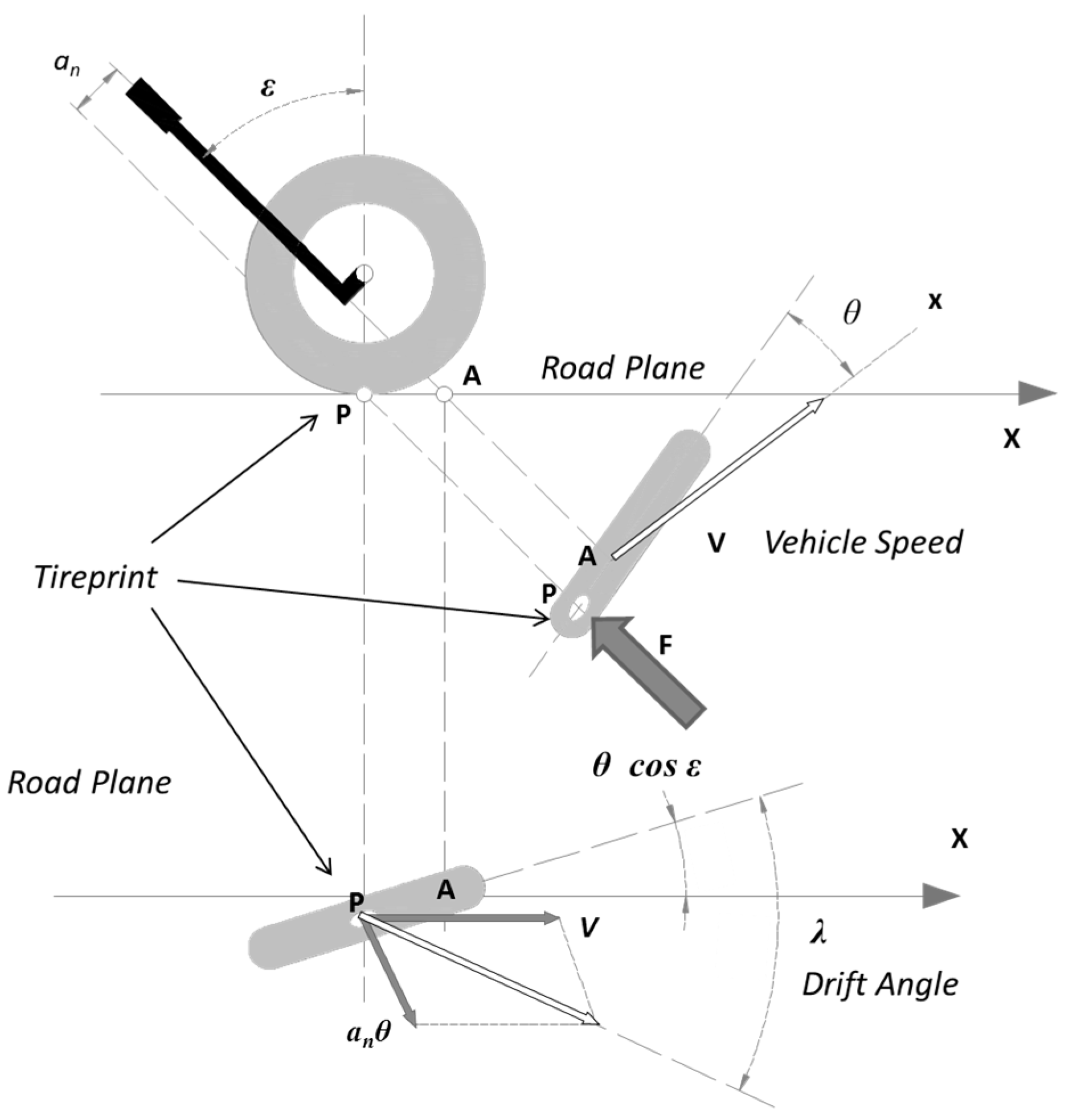
The wobble mode is a dynamic instability state of a motorcycle which consists of a steering oscillation around its rotation axis. Wobble frequencies typically vary between 4 and 10 Hz [
19]. The phenomenon begins with small steering oscillations of a few degrees that, if not promptly damped, in the most severe cases can increase in amplitude to become a violent movement of the handlebar known as a ‘tank slapper’. Assuming that the wobble mode occurs independently of the roll mode around the rear axle, the front axle can be simplified as a rigid body with only one degree of freedom, i.e., the rotation around the steering axis (
Figure 1) [
16].
The natural frequency ω and the damping ratio
ζ of the front wheel are described in Equations (1) and (2). The front tire and fork (
Kλf), vehicle speed (
V), steering tilt (
ε), and the damping coefficient are all influenced by the moment of inertia relative to the steering axis (
IAf), the motorcycle trail (
an), and the damping coefficient of the steering damper (
c).
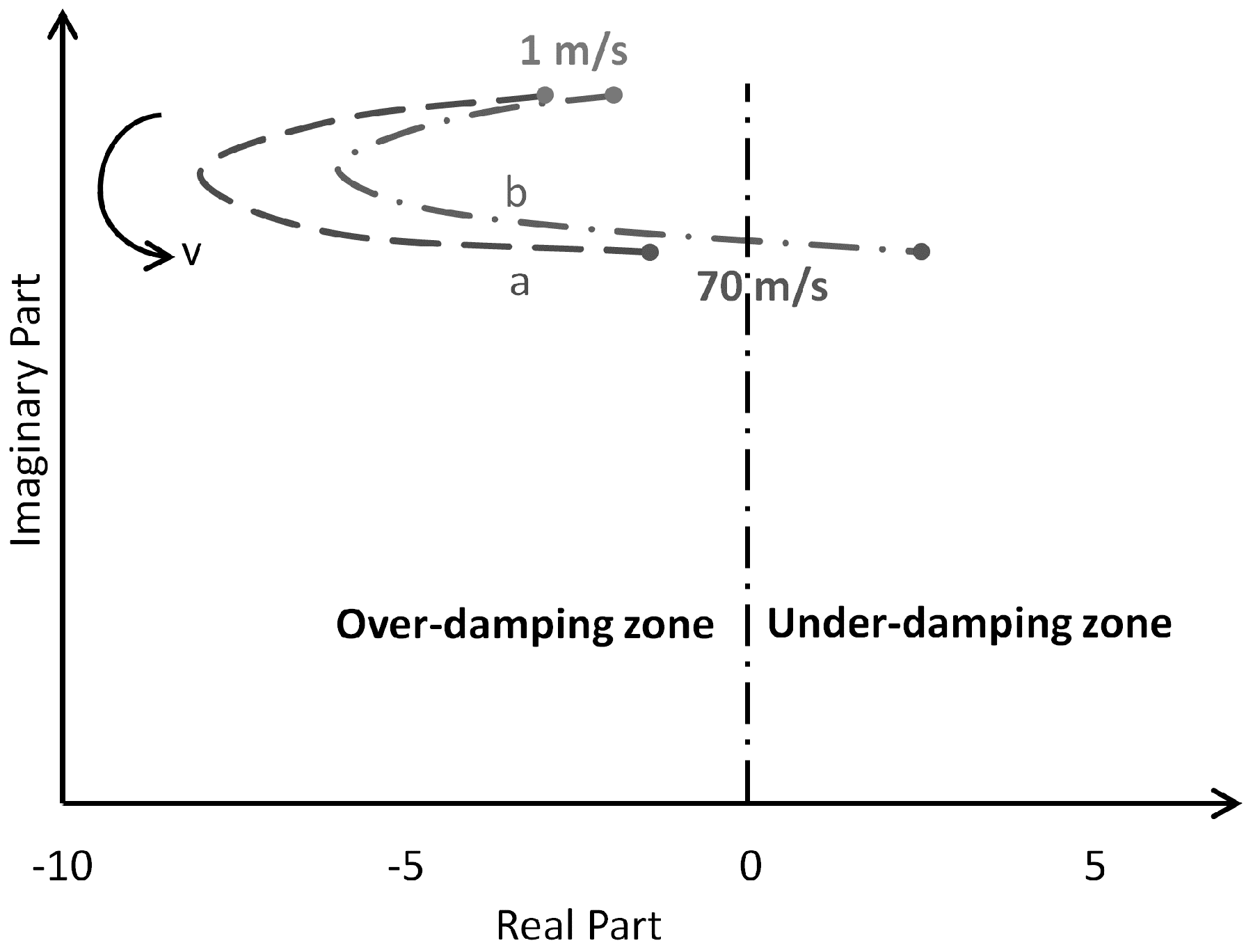
In Equations (1) and (2), the motorcycle geometry strongly influences the wobble mode, and without a steering damper, the damping ratio (
ζ) tends towards zero with increasing vehicle speed.
Figure 2 shows the root loci for a motorcycle in straight-line travel through a speed range from 1.0 m/s to 70.0 m/s and two different values of steer damping (a) 7.0 Nms/rad, (b) to 0.9 Nms/rad). We see that with high vehicle speed and low damping values, the wobble phenomenon is not damped. The combined effect of these parameters makes the motorcycle unstable and therefore riding can quickly become unsafe [
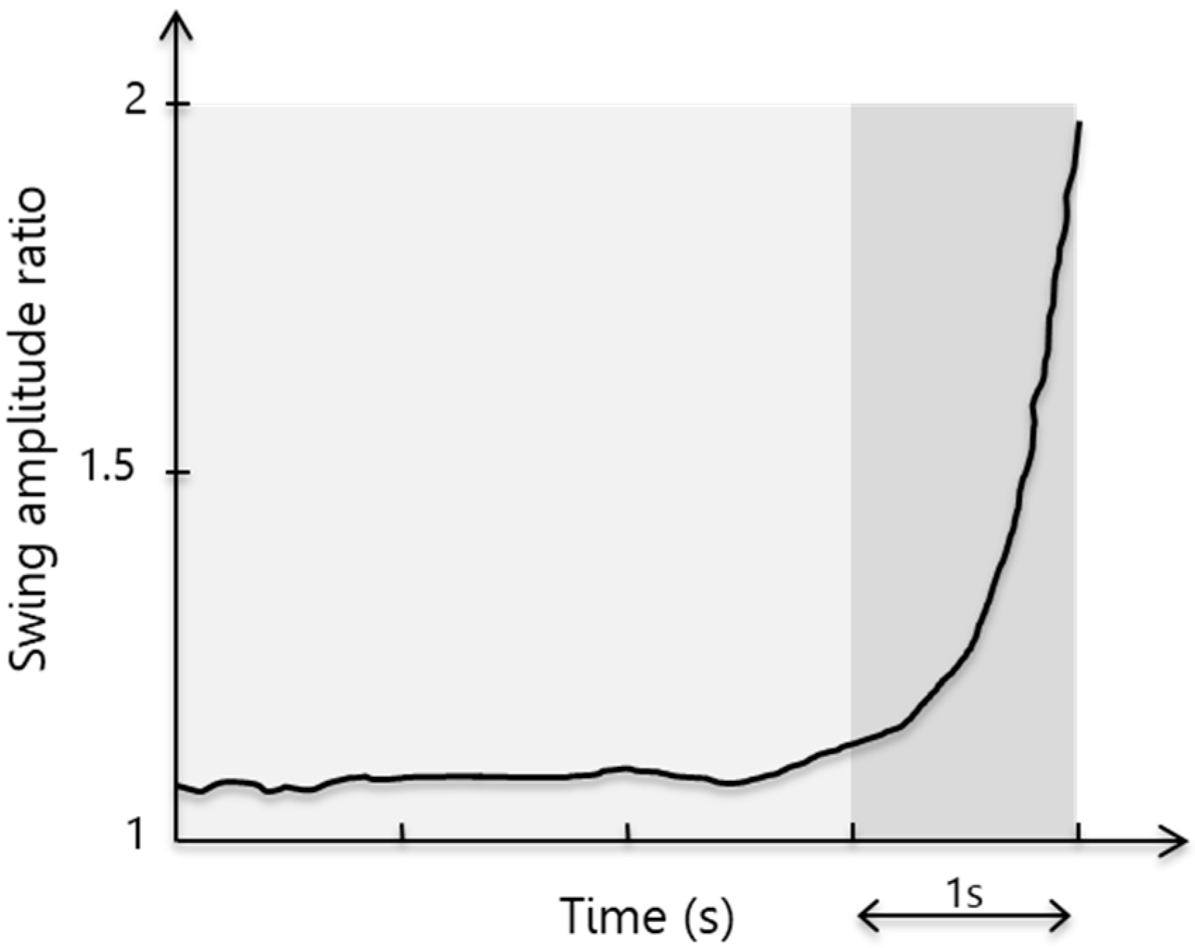
41]. For small-amplitude wobble, the swing amplitude ratio is approximately constant, (light grey,
Figure 3) allowing the rider to regain control of the motorcycle. With a high amplitude of wobble, the swing amplitude ratio quickly grows (dark grey,
Figure 3), doubling in less than one second, and making the motorcycle increasingly difficult to control. The damping coefficient of the steering damper is, therefore, a critical factor in the stability of a motorcycle, especially at high speeds when the wobble phenomenon is most likely to occur.
3. Conceptual Design and Analytical Model
The objective was to design a semi-active MR fluid-based steering damper that is fully integrated into a motorcycle steering column and easy to assemble and disassemble. We followed the performance specifications set out by Sharp et al. [
19]: minimal damping at low speed with the guarantee of rapid increase in damping upon the onset of wobble. The lower value of the steering torque without magnetic field was set at 0.9 Nms/rad, while the upper value with the magnetic field was set at 7 Nms/rad. The operating range of the steering damper field (
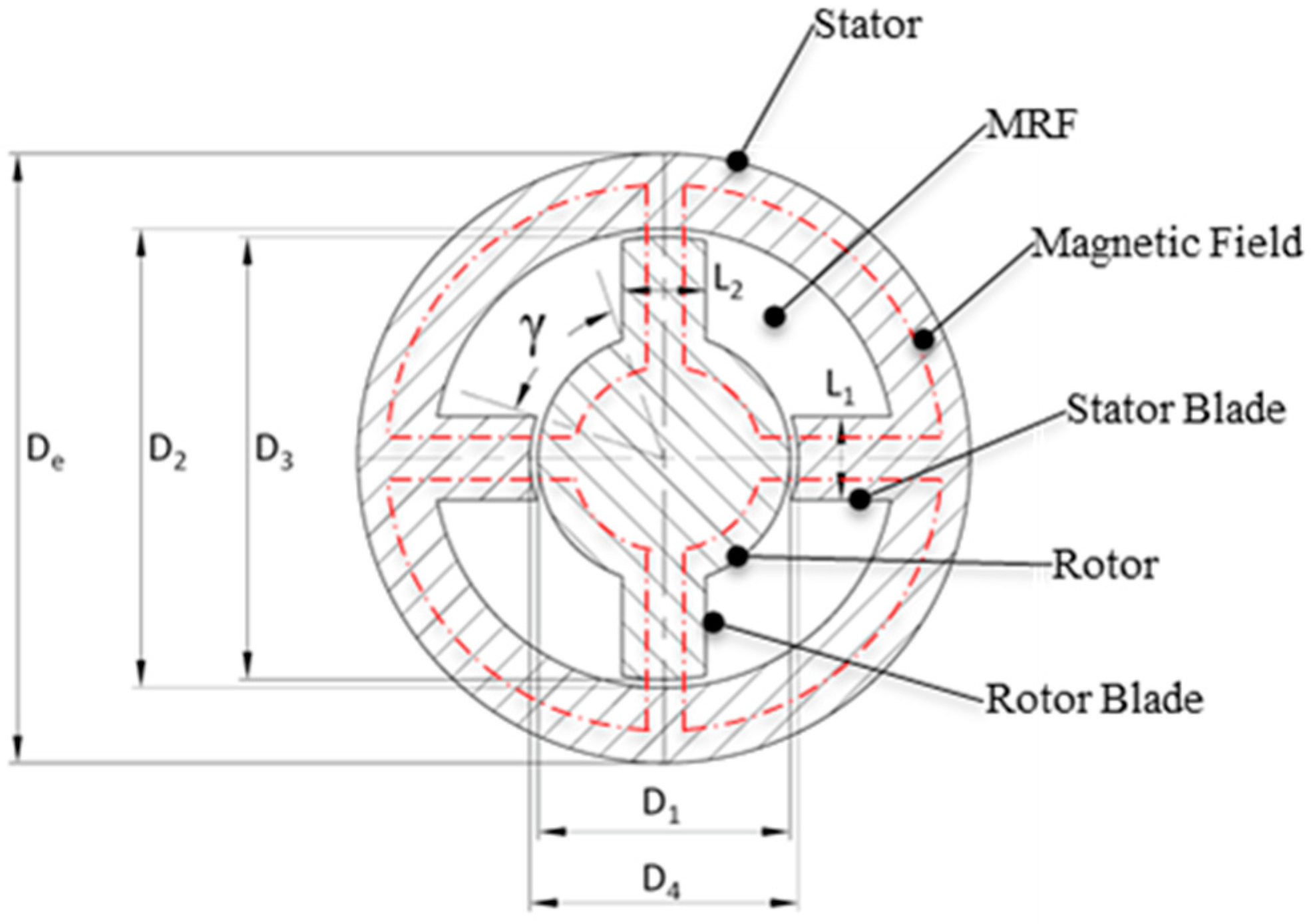
β) was fixed at ±3° to 7°. The conceptual solution was comprised of a stator and a rotor element (
Figure 4). The stator defines the inner surface, while the rotor element defines the outer surface. An innovative feature was an annular gap containing the MRF inserted between the stator and rotor, which acted to increase the strength of the handlebar.
Two caps located at the axial ends created a chamber. The steering tube acts as the stator and the steering shaft as the rotor, thus fully integrating the damper into the steering column. The rotor and stator each had two blades extending along the entire axial length of the system, thereby dividing the fluid volume into four chambers. Four gaps permitted the fluid to flow between chambers during the steering oscillations. For regulation of the damping characteristic, a pair of coils were installed on the stator blades to generate a variable magnetic field that crosses the gaps orthogonal to the fluid flow in order to maximize the MR fluid effects [
34]. Additional gaps were located between caps and rotor and stator, respectively. The extended axial configuration of the device compensates for the limited space available in the radial dimension, thereby ensuring the generation of adequate torque values (i.e., the damping characteristic).
An analytical model was used to perform the preliminary sizing of the conceptual solution and to support the three-dimensional design and finite element (FE) validation.
Figure 4 provides a schematic of the damper in cross-section.
3.1. Magnetic Field Dimensioning
The MRF-132DG fluid by LORD Corporation® was selected for the design [
46]. The target for magnetic field strength across the gaps was fixed at 90 kA/m. This produced a yield stress (
τy) of about 60% of the maximum
τy achievable for the MR fluid, ensuring that the fluid worked far from its saturation zone. All the components were made of steel. The magnetic field is expressed by Equation (3)
where
N is the number of coils, I is the electrical current,
Hm is the value of the magnetic field into the metal,
K is the mean length of the magnetic field lines into the metal,
Hg is the value of the magnetic field into the gaps and
g is the total thickness of the gaps. In the absence of magnetic field leakage, the magnetic flux Φ is preserved and the magnetic field into the metal can be expressed by Equation (4)
where
μf and
μm are the relative permeabilities of the MR fluid (3 H/m) [
46] and the ferritic steel (1100 H/m) [
47], respectively. Assuming
N = 100 and
I = 2 A, we obtained the values for
Hg and
Hm from Equations (3) and (4):
Hg = 90.9 kA/m,
Hm = 0.25 kA/m. The
Hg value found was very close to the target of 90 kA/m, while
Hm was negligible in comparison to
Hg. Equations (3) and (4) show also that the length of the steering tube does not directly influence the magnetic field intensity.
3.2. Damping Torque Calculation
The geometry of the steering damper (length of the blades L and height h of the damper) determine the value of the damping torque (
Figure 4). Thus, the length (L) had to be minimized, to allow the system an unrestricted rotation range comparable with normal steering solutions. The maximum steering angle (α) was set at ±40° from the central position and the overall height (
h) was set at 150 mm.
The following assumptions were made:
- ✓
homogeneous, monophasic, and incompressible fluid
- ✓
magnetic field H and yield stress τy (H) uniform within the meatus and zero elsewhere
- ✓
magnetic field H orthogonal to the fluid flow direction
- ✓
laminar and stationary flows within the meatus
- ✓
pressure losses null, determined by the viscosity of the fluid outside of the meatus
- ✓
inlet and outlet concentrated pressure losses to the meatus: Rc = 1.5 ρv2/2 (where v is the average velocity of the flow inside the meatus)
The maximum flow rate (
Q) of fluid between the two chambers and the equivalent diameter of the meatus of fluid (
Deq) are obtained from the geometric parameters (see
Figure 4) using Equations (5) and (6)
where
vma is the average velocity of the blades at the maximum rotational velocity,
A is the longitudinal area of a single blade,
S and
P are the surface and perimeter of the gaps respectively, and
g is the gap thickness. In the absence of a magnetic field, an MRF may be assumed to act like a Newtonian fluid. The total pressure losses
R through a channel are obtained by Equation (7)
where
ρ and
µ are, respectively, the density and the viscosity of the MR fluid, k is the friction coefficient,
Re is the Reynolds number, and
um is the average velocity of flow through the gaps.
Supposing an equal flow repartition between the gaps, the total pressure loss between two adjacent chambers was found to be 2
R. Defining the design values for the remaining parameters (wobble frequency:
f = 10 Hz; maximum oscillation angle:
βmax = ± 7°, with a maximum rotation speed of 7.68 rad/s), the damping torque C provided by the system without a magnetic field is calculated as Equation (9)
where
A is the area of each blade that separates two adjacent chambers,
b is the torque arm of the damper, and
rma is the average radius of the shaft blades.
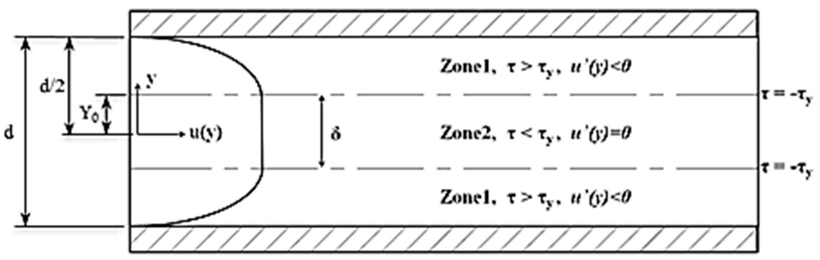
Applying a magnetic field, the Newtonian model is no longer suitable for describing to describe the behavior of the MRF, and it is necessary to switch to the Bingham model. Bingham fluids are non-Newtonian fluids characterized by a yield stress
τy beyond which the tangential stress is linear with the increasing gradient velocity (as in a Newtonian fluid). In a fully-developed one-dimensional flow in a circular duct (
Figure 5), the shear stress (
) is expressed by the Equations (10) and (11)
where
τy is the yield stress, the signum function (
sgn) is +1 for a positive argument and −1 for a negative one and
η is the apparent viscosity [
45].
Using the Bingham fluid theory and considering the two flow zones active in this type of fluid (
Figure 5), each flow is expressed as a function of the pressure gradient
Δp through the duct. In a steady-state flow condition, the shear stress (
τ) applied to a generic radial part (
y) of the fluid can be deduced from the equilibrium Equations (12) and (13).
Through Equations (10) and (13), the velocity gradient is derived through Equation (14), and the flow velocity and rate by Equations (15)–(18), respectively.
For zone 2 (
Figure 5) the velocity gradient is null (
), and the Equation (14) permits calculation of the dimension
δ of the zone 2 Equation (19)
The
Δp is determined by iteration on the Equations (16–18) and the value obtained is about 305 kPa. Finally,
Δp is added to the concentrated losses in inlet and outlet
Rc, and the total pressure losses through a gap
R and the maximum torque applying a magnetic field
CMAX are obtained using Equations (20) and (21)
The torque obtained in the absence of the magnetic field matched the specifications, while the torque obtained with the magnetic field applied was approximately 8% lower than the required minimum (
Table 1).
4. Optimization Process via Multiphysics Numerical Analysis
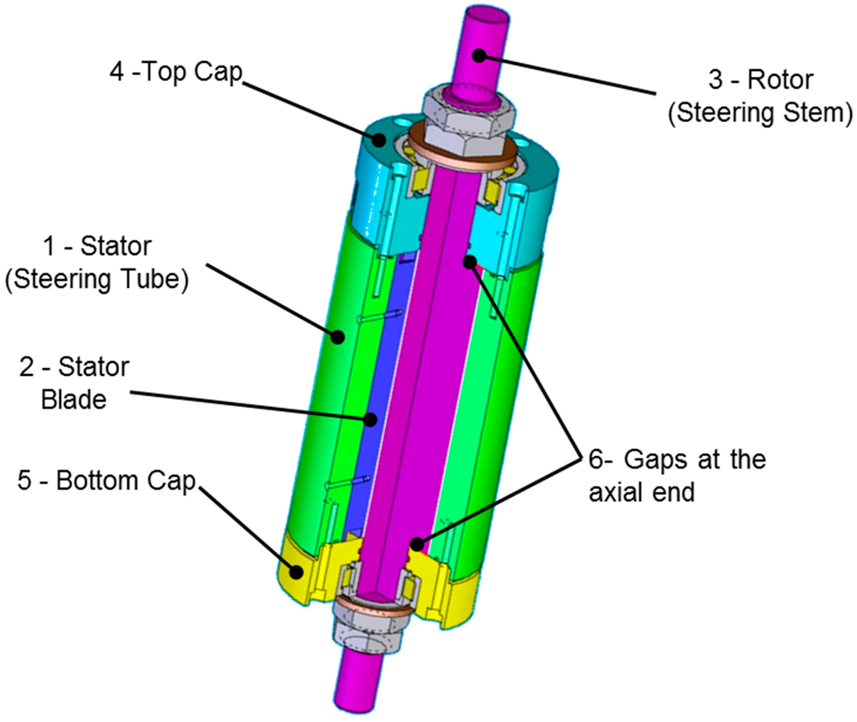
Following the definition of the conceptual scheme, a three-dimensional solution was developed (
Figure 6).
As a result of its predominantly axial design and a limited radial size, the conceptual steering damper solution was fully integrated into the motorcycle steering tube. The researchers tried also to solve the contact related problems between seals and MRF avoiding the direct interaction between the two: literature showed an increase in the seal wear by the use of this type of fluids [
42,
43,
44,
45]. The damper was designed for an endless life when subjected to the time-varying operational loads.
A 3D multiphysics finite element analysis was performed to evaluate the influence of these various factors on damper performance in order to determine its optimal configuration. The coupled multiphysics analysis is based on computational fluid dynamics [
48,
49] and magnetic field simulation.
The geometry of the damper caps (4 and 5 in
Figure 6) and the gap distances between the stator/rotor and the caps influence the distribution of the magnetic field. Most of the magnetic field goes through the damper case instead of the MRF and this influences the flow rate. Thus, the flow rate increases in comparison to the analytical model which reduces the pressure losses (i.e., torque value) generated between the two chambers.
As a result, the preliminary sizing scheme given in
Figure 4 has been modified by reducing all the gaps between the rotor and stator from 1 mm to 0.5 mm. The FE modelling and analysis were carried out in Comsol Multiphysics version 3.5 software.
Boundary Conditions
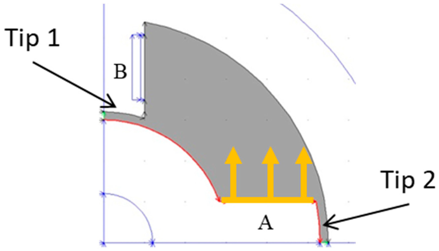
Considering the geometry of the system, a 3D analysis of the magnetic field was performed on one-quarter of the model (
Figure 7). Four hexahedrons of equal cross-sectional area A were used to represent the coils. The electric current density
J was selected according to
J∙A =
N∙I, where
N is the number of coils, and I is the electric current. The model assumes immersion in the air.
Using anti-symmetry boundary conditions applied on one-quarter of the inner volume, the pressure losses were calculated for a single fluid chamber (
Figure 7). The flow rate was determined as generated from only one blade surface (yellow,
Figure 7).
5. Results and Discussion
Using a 3D magnetic-fluid coupled analysis, acceptable torque values were obtained by varying the internal dimensions of the damper components and the width of the gaps while keeping the external size of the steering tube constant (
Figure 4 and
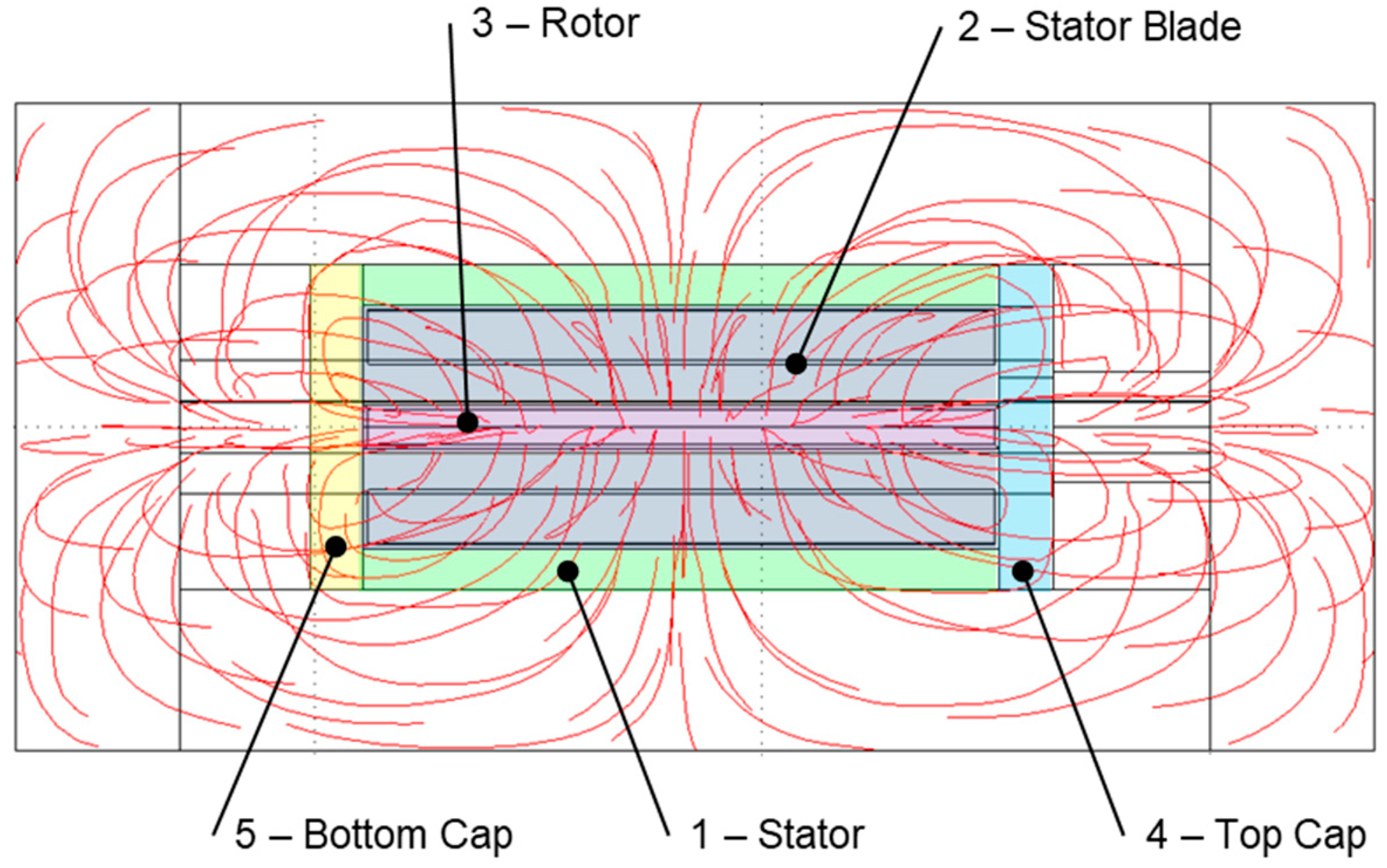
Figure 6). The magnetic streamlines are shown in
Figure 8, in which the steering axis is horizontal. Due to the presence of the two caps (4 and 5,
Figure 8), the magnetic field shows both radial and axial components, while the latter was previously neglected in the analytical model analysis (
Figure 4). This result caused a change in the magnetic field intensity through the gaps which was not evident from the conceptual analysis.
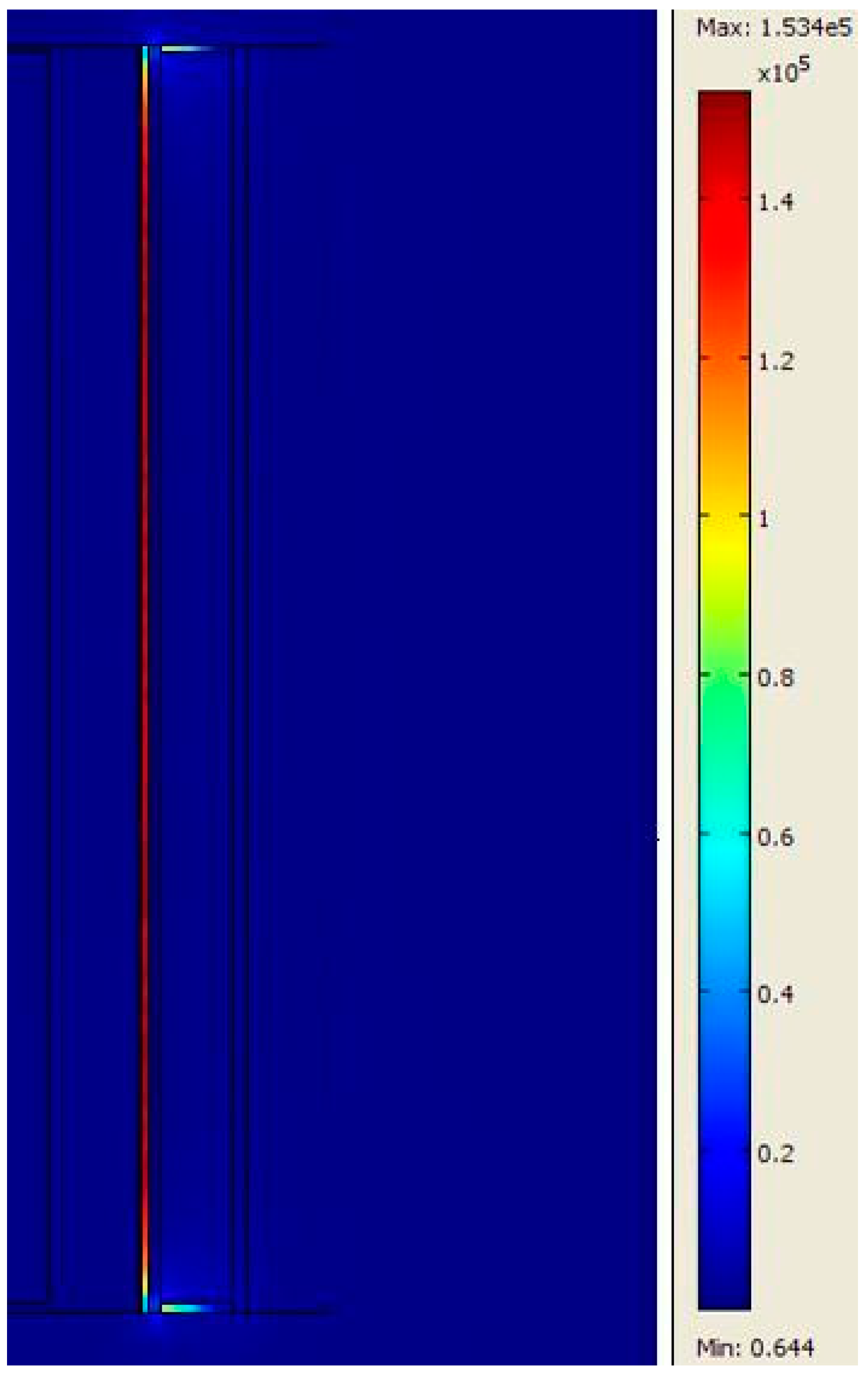
Figure 9 shows the value of the magnetic field through the fluid gaps at the tip (2,
Figure 7) of the rotor blade. The 3D magnetic model analysis showed a higher magnetic field generation than the analytical solution (≈150 kA/m vs ≈ 90 kA/m,
Section 3.2). This is because most of the magnetic field flow through the caps instead of the fluid gaps at the rotor and stator tips (4 and 5,
Figure 8). Nonetheless, the magnetic field is higher near the coil and lower at the cap gaps.
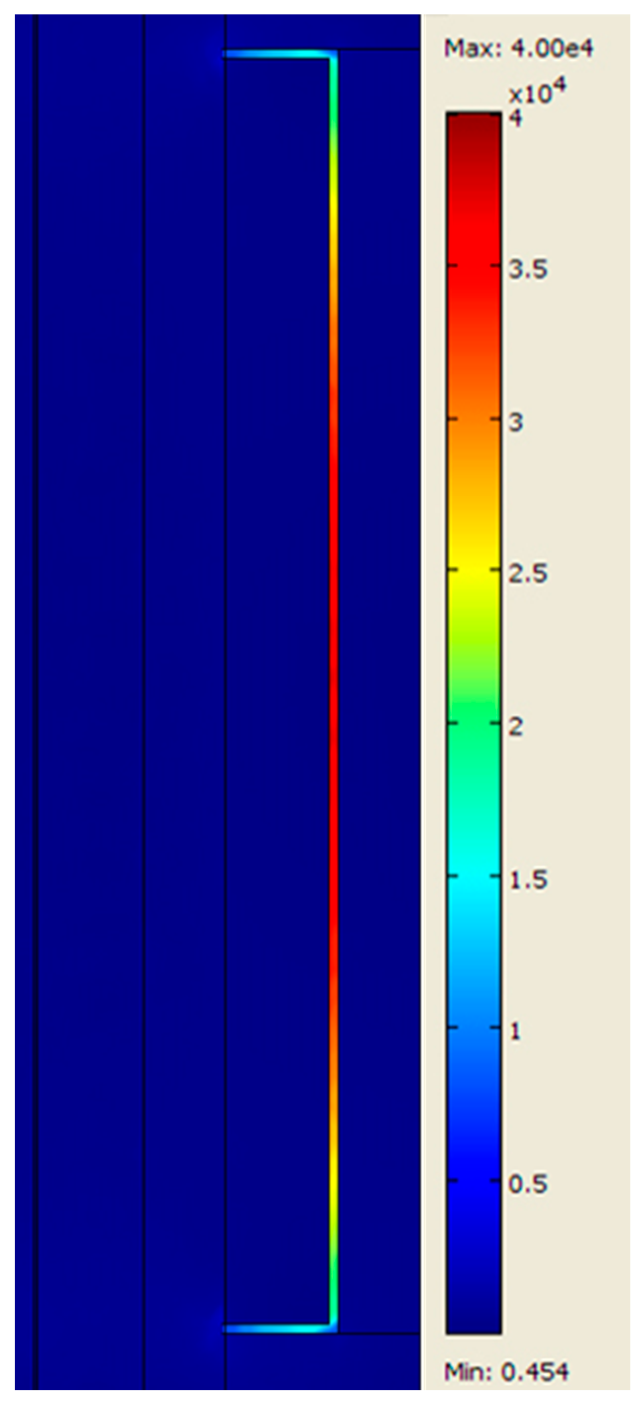
The magnetic field intensity through the fluid gaps at the tip (1,
Figure 7) of the stator blade is shown in
Figure 10. The magnetic field shows a maximum intensity in the central zone of approximately 40 kA/m, that is, less than 50% of the value in the analytical solution (
Section 3.2). A further decrease is shown close to the caps due to the distortion of the flow lines in the 3D model (
Figure 10). As a consequence of the three-dimensional distribution of the magnetic field, only a small part of the magnetic field crosses the meatus between the rotor blades and the caps (≈16 kA/m).
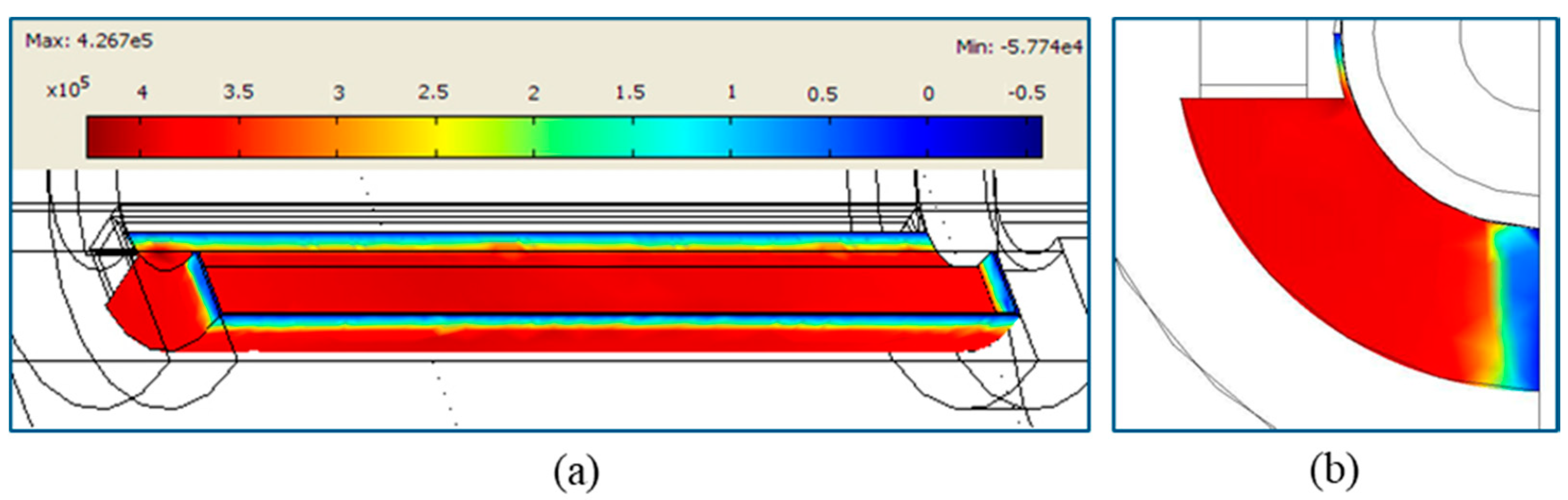
The pressure distribution with the magnetic field is shown in
Figure 11. The mean half-chamber pressure was 400 kPa. Therefore, working in anti-symmetry, the total pressure losses
between two adjacent chambers are
, and the minimum and maximum torque values are obtained by Equations (22) and (23)
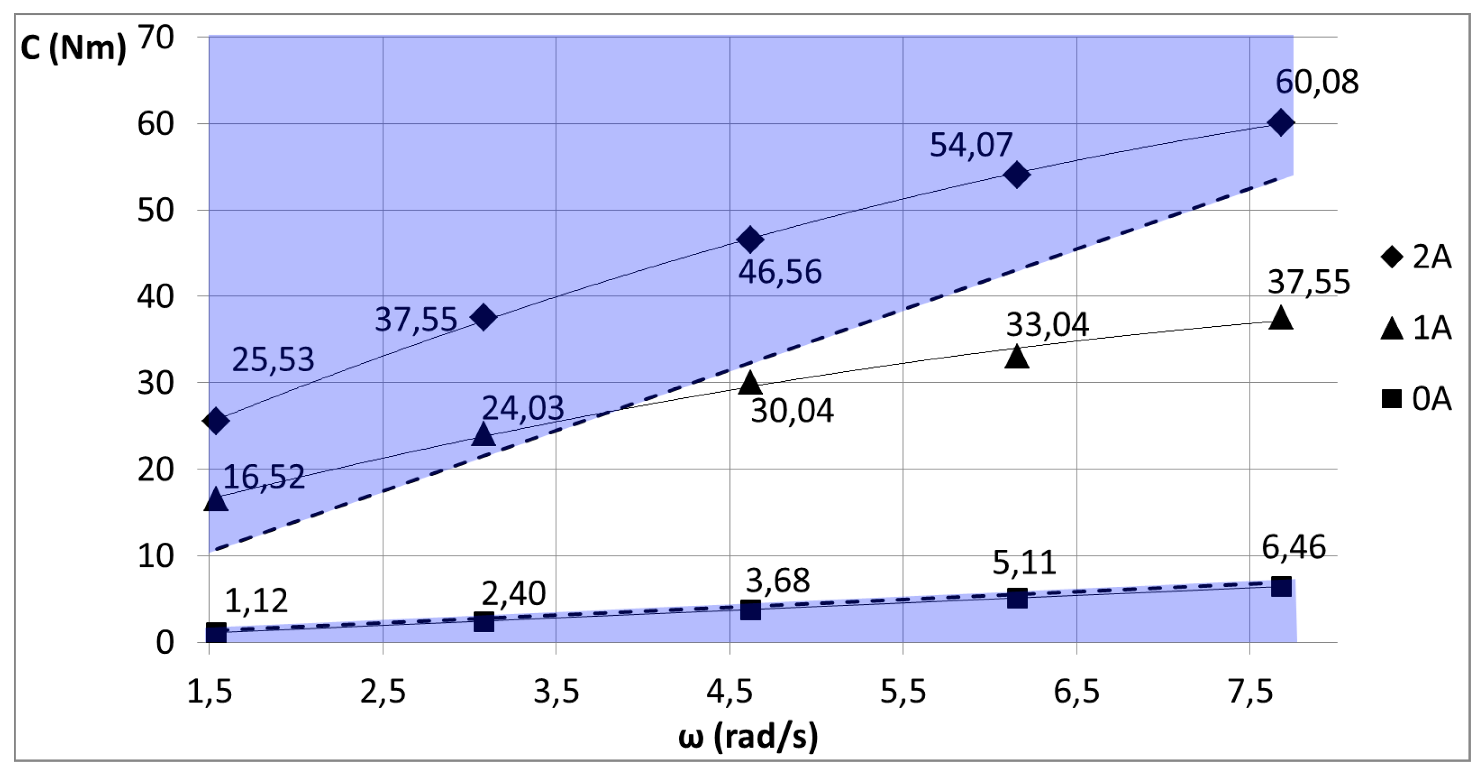
The torque obtained from the 3D FE analysis fully met the design specifications (
Table 2). Further analyses were carried out to obtain the operative field as a function of the angular steering speed and the magnetic field (
Figure 12). The purple sections cover the acceptability ranges of the damping values with and without the magnetic field. The graph shows that the steering damper provided the required specification throughout the whole speed range considered, applying an electric current between 0 and 2 A. The damping coefficient can be increased by more than 10 times when the maximum electric current is applied. The 3D conceptual solution implemented certain innovative features with specific advantages, compared to the traditional steering dampers: (i) high torque values; (ii) a limited radial dimension; (iii) full integration into the motorcycle steering tube; (iv) simplicity in the chamber geometry allowing easy fabrication; (v) absence of sealing material in direct contact with the MRF.
6. Conclusions
In this paper, we described the conceptual development and design of an innovative steering damper for PTWs. The objectives underlying the design requirements were: (1) development of a damper able to functionally complement advanced driver assistance systems, (2) improvement of PTW safety through prevention of wobble instability as well as enhancement of vehicle comfort and handling, (3) a design solution for integration within the PTW steering series, (4) easy assembly and disassembly, and (5) low maintenance requirements.
All of these features have been implemented in a semi-active MRF-based damper, fully integrated into the motorcycle steering system. A 3D FE multiphysics magnetic-fluid analysis has been necessary following the initial conceptual analysis, in order to determine the precise measurements of the size of the gaps to produce the system performance targets. The final specifications can produce a wide variable range in damping force with a multiplying factor up to 10 at a maximum electrical current of 2 A. Thus, the proposed steering damper can easily generate either lower or higher torque values as the situation demands, ensuring the best balance between riding comfort and safety intervention.
The innovative features of the proposed design provide specific advantages compared to traditional steering dampers, those being (i) a wide range of adjustable torque values, (ii) total integration into the motorcycle steering column enabled by an axial design and the limited radial size, (iii) simple chamber geometry that allows easy manufacture, (iv) longer seal life due to the absence of direct contact between seals and MRF.


 ,
, 


