Article

Kineto-Static Analysis of a Wrist Rehabilitation Robot with Compliance and Passive Joints for Joint Misalignment Compensation †

Department of Mechanical Engineering, Tokyo Institute of Technology, Tokyo 152-8552, Japan
*
Author to whom correspondence should be addressed.
This paper is an extended version of our paper published in Liu, Y.-C.; Takeda, Y. Kineto-static Analysis of a Wrist Rehabilitation Robot with Compliant Elements and Supplementary Passive Joints to Compensate the Joint Misalignment. In Proceedings of the 25th Jc-IFToMM Symposium, 2nd International Jc-IFToMM Symposium, Kanagawa, Japan, 25–26 October 2019.
Machines 2020, 8(2), 23; https://doi.org/10.3390/machines8020023
Submission received: 31 March 2020 / Revised: 29 April 2020 / Accepted: 29 April 2020 / Published: 2 May 2020
(This article belongs to the Special Issue Selected Papers from Advances of Japanese Machine Design)

Abstract

:
In this paper, we present a kineto-static analysis on a wrist rehabilitation robot to compensate for joint misalignment between human and robot joints. Since joint misalignment has proved to generate user–device interaction forces, which reduce the comfort and safety of the wearable devices and limit the user’s willingness to use it. The use of compliance and the addition of passive joints for joint misalignment compensation are discussed. In order to study the effect of the initial offset, we find that the initial offset in the direction perpendicular to the forearm causes a larger unwanted force. In addition, the use of the softest compliance can minimize unwanted force by 38% compared to the case without compliance. Furthermore, the effect of the addition of passive joints to the exoskeleton is investigated. From the analysis results, the soft part of the human being is regarded as a passive joint with the ability to compensate for joint misalignment. Moreover, the influence of the soft characteristics of human limbs should be considered when designing a wearable robot. This soft property, causing the movement of the braces, results in reducing the angular range of the wrist. Through the analysis results, we provide effective ideas for joint misalignment compensation to fulfill a comfortable and safer robot design.

1. Introduction

The human upper limb motor function is essential for everyday human activities. Patients with a disability in the upper arm need rehabilitation to recover their capacity to accomplish activities of daily livings (ADLs). A frequent and intensive rehabilitation exercise guided by well-trained clinicians helps patients to regain their damaged function through a quicker and improved recovery throughout the rehabilitation process. A drawback of such a method, though, is that a patient is expected to work person to person with a therapist. The lack and exhaustion of therapists may cause unsatisfactory recovery outcome over a long, tedious, and labor-intensive cycle. To overcome this issue, robot-assisted therapy can provide intensive and continuous treatment to reduce the burden of therapists, which has proved successful in rehabilitation therapy [1].
In the past four decades, robot-assisted therapy has increasingly developed [2]. Norouzi-Gheidari et al. [3] performed a comprehensive analysis and found that robot-assisted treatment provides a successful method for restoring human joint motion function. In general, robotics can perform repeated rehabilitation treatments over a longer period, and it has proved to be an effective approach. In the meantime, with the advancement of entertaining assistance technology connected to robotics, patients will be more willing to engage in rehabilitation towards improved recovery results.
The wrist joint is one of the complex human joints. It facilitates the movement and transmission of force through five metacarpals, eight carpal bones, radius, and ulna. Bones and tissues, including tendons, ligaments, nerves, skin and so on, are also combined with the human wrist. It binds the forearm and the hand, allowing flexion-extension and ulnar-radial deviation movements by forearm muscles. In fact, the wrist joint plays a key role in performing various essential everyday tasks [4]. Therefore, it is necessary to regain the range of motion (ROM) of the wrist to carry out hand functions.
A wide variety of robotic devices for wrist rehabilitation have been developed for years [5,6,7]. While rehabilitation robots have progressively played a crucial role in clinical use, satisfactory results cannot be received in many rehabilitation robots. Especially in the case of exoskeletons, the possibility of misalignment between the robot and the patient’s joint will produce unwanted forces [8]. It may make the users feel discomfort or result in a dangerous condition during rehabilitation. To deal with this issue, our previous works in [9,10] have studied the unwanted forces generated by the joint misalignment of a rehabilitation robot for wrist movements in flexion/extension. Compensation for joint misalignment is available with the use of compliant elements and the addition of passive joints.
This paper is an extended version of the research described in [10]. It addresses the impact of the initial offset and the usage of compliant components. The wrist flexion and extension motion are the goal of rehabilitation. The analytical model of the RRPR mechanism is investigated. Here, R and P denote revolute and prismatic joints, respectively. Additionally, passive joints are added to the exoskeleton for the compensation of misalignment. The target of the analysis is the RRRR four-bar linkage. We extend our previous work through the optimization of each link length of the mechanism, which influences the performance of the robot. The finding of the analysis will contribute to effective ideas to design a robot with the comfort and safety of patients.

2. Methods

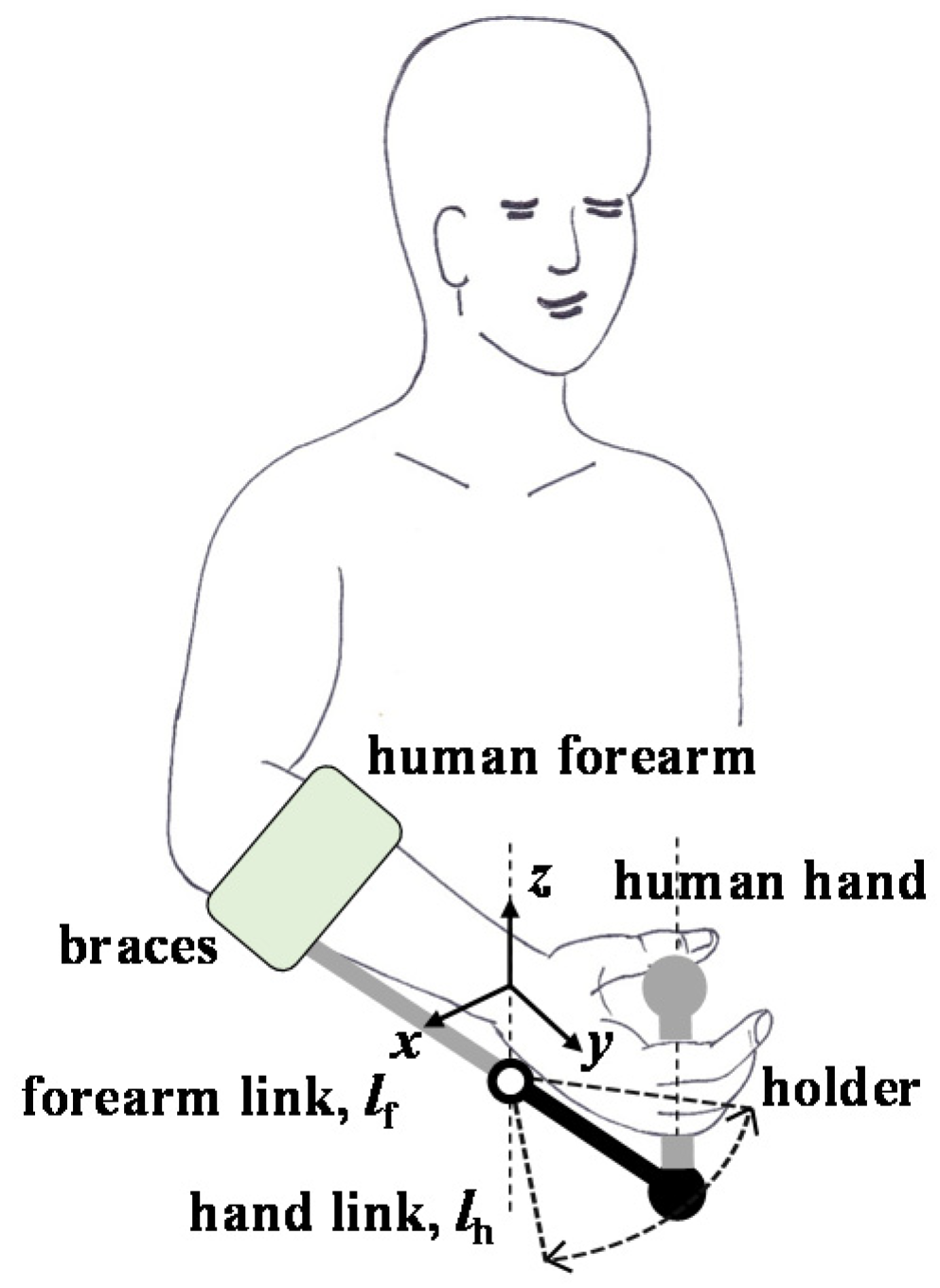
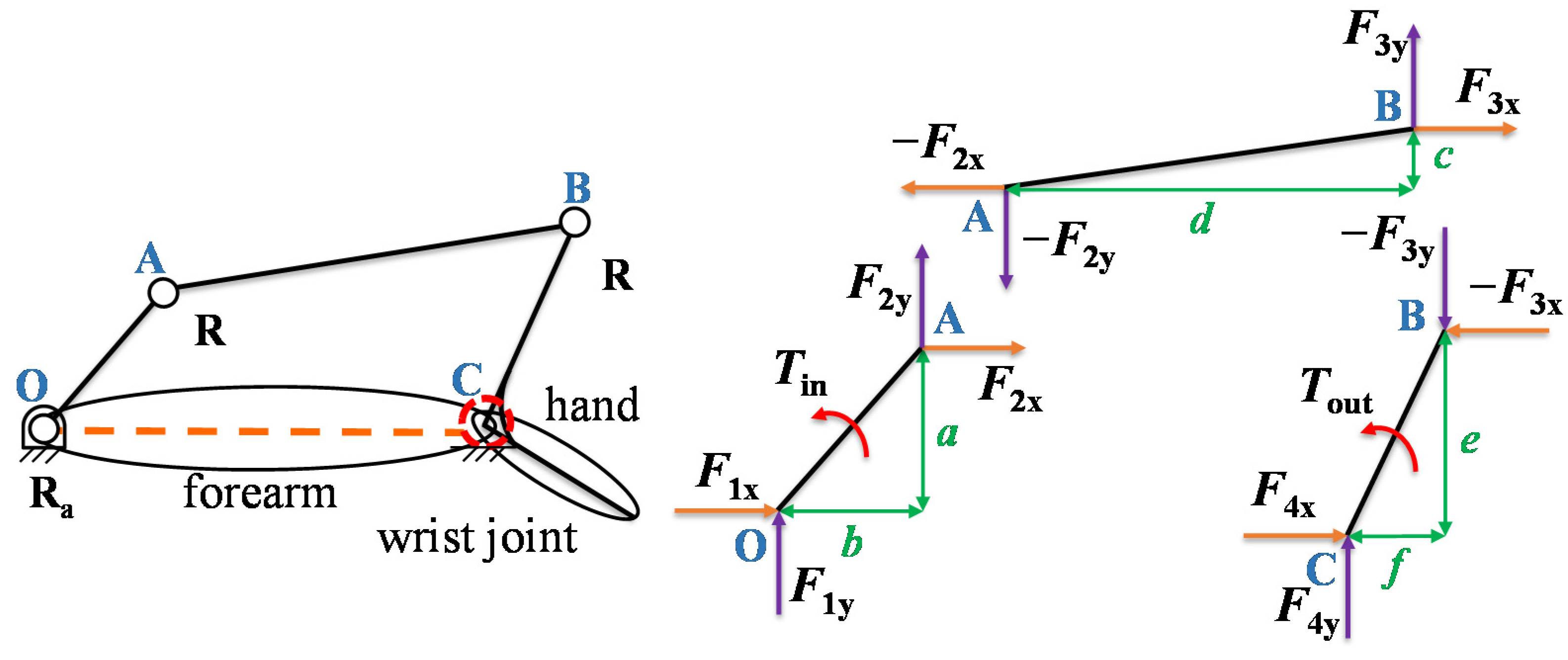
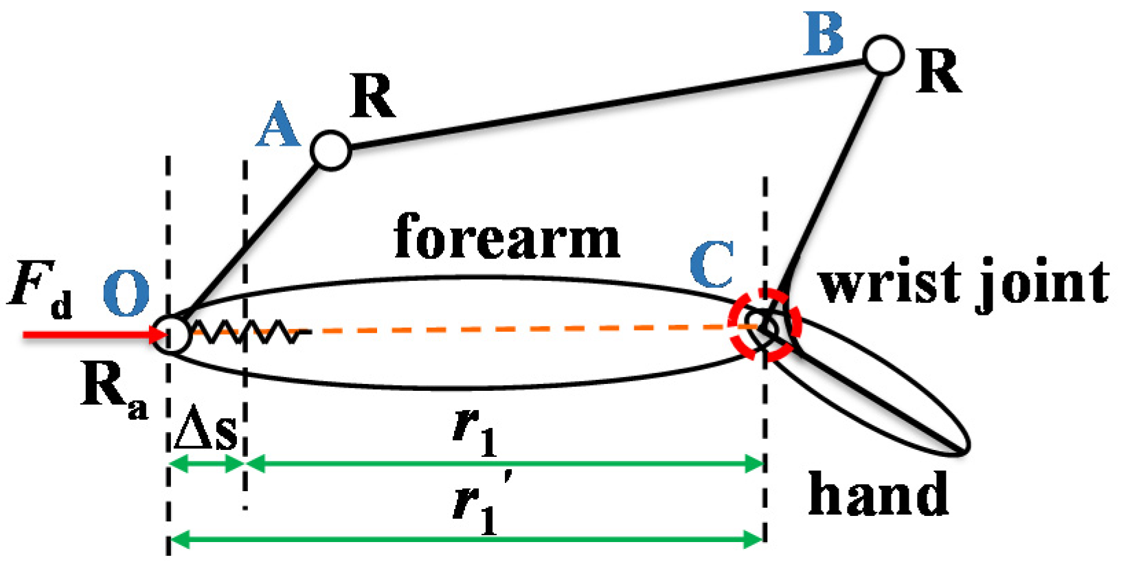
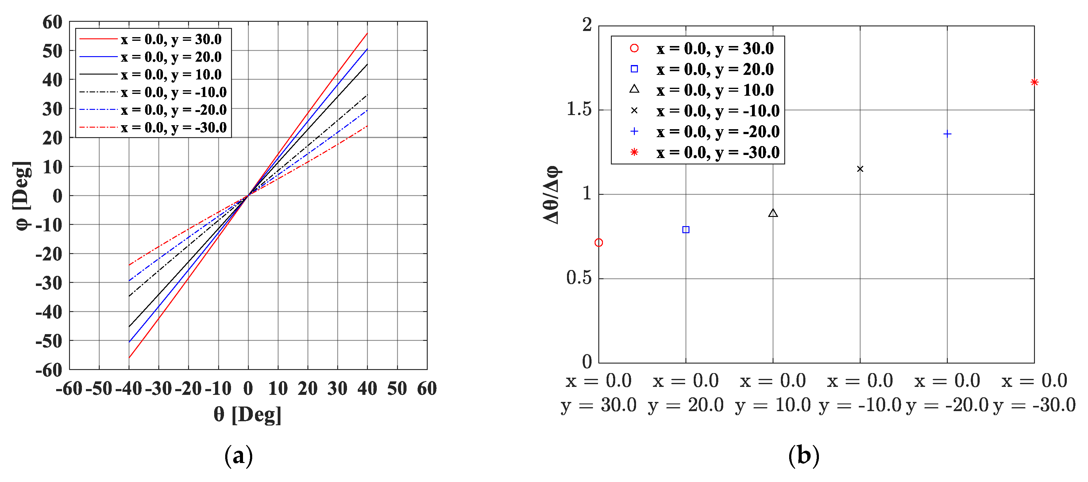
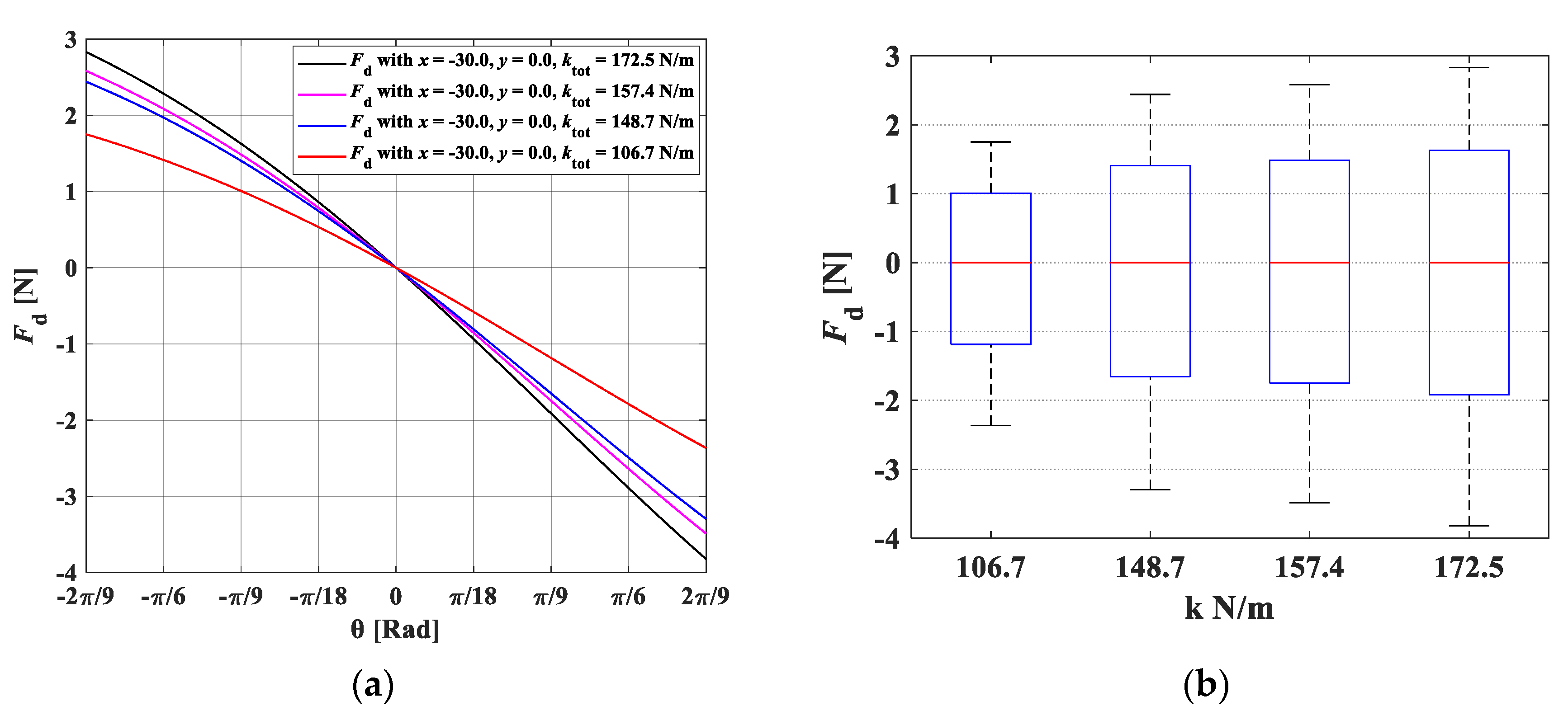
2.1. Static Force Analysis of a Wrist Rehabilitation Robot

Figure 1 shows a schematic illustration of a wrist rehabilitation robot. Although the wrist joint has two degrees of freedom (DOF), we focus on this 1-DOF robot to achieve wrist flexion/extension for recovery treatment. A coordinate system is defined, and its origin is fixed on the forearm located at the center of the human wrist joint, CRhum-xyz. The y-coordinate axis aligns along the forearm pointing towards the hand, and the x-coordinate axis is parallel to the considered rotation axis of the wrist joint. The user’s forearm is fastened by the braces to the forearm link (lf). Moreover, the human hand is securely fixed to the holder. For the hand flexion/extension movement, the range of motion (ROM) of the wrist joint is set from −40° to 40° according to the investigation provided by Ryu et al. [4]. When the hand is at a neutral position, the wrist joint angle is set as zero.
An analytical model of the robot mounted on the human forearm with an initial offset is shown in Figure 2. The points CRhum and CRexo marked in Figure 2a represent the rotation centers of the human wrist and of the robot joint, respectively. Taking into consideration the characteristics of human hand soft tissue, the concept of dynamic pair proposed in [11] is applied. Here, the dynamic pair is described as a model of linking parts between humans and robots. The effects of spring and damping are involved in the dynamic pair. Therefore, the human hand is supposed as an element including a spring and a damper. The displacement between CRhum and the hand-attached point H varies throughout the rehabilitation motion. The unwanted force Fd runs alongside the hand by restricting the displacement in the same direction. In this research, we make the following assumptions: 1. The braces are tightly attached to the forearm and forearm deformation is neglected. 2. The rehabilitation movement is considered to be quasi-static so that we will not take into account the dynamic effect. This means that we presume that the human parts have a spring-like behavior without damping effects. 3. Fingers and forearm effects are not considered during the entire motion.
Based on the assumptions above, we adopt an analytical model developed by Schiele [12] to determine the unwanted force caused by joint misalignment. The unwanted force Fd can be described as follows:
F d = k t o t · d t o t ( θ , l h , x , y )
where dtot is the displacement of the hand-attached point along with the hand, ktot is the total spring constant of the hand and holder, θ is the hand rotation angle, which is defined as an angle between the positive y-axis and the line passing through the CRhum and H, lh is the hand link length, which is set as 70 mm, and x,y indicates the initial offsets in x and y directions. The beginning and the end of the moving processes are illustrated in Figure 2b,c, where lbegin is the distance between CRhum and the hand-attached point H at θ = 0 and lend is the distance at a specified hand rotation angle θ = θend. The total displacement can be calculated as follows:
d t o t = l b e g i n l e n d
l b e g i n = y + l h · cos ( sin 1 ( x / l h ) )
ψ = sin 1 ( x 2 + y 2 · sin ( θ + tan 1 ( x y ) ) l h )
l e n d = l h 2 + x 2 + y 2 2 · l h · x 2 + y 2 · cos ( π ψ θ e n d tan 1 ( x y ) )
The displacement (dtot) relies on the angle of rotation of the hand (Δθ) and the offsets x and y. In addition, regarding the compliance of the human hand and holder, we considered and modeled these two parts as two springs, which are connected in series with each other. If the displacement (dtot) and the total spring constant (ktot) are obtained, the unwanted force (Fd) can be calculated.

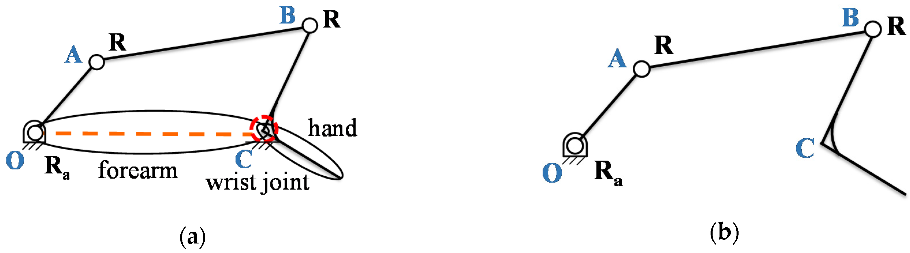
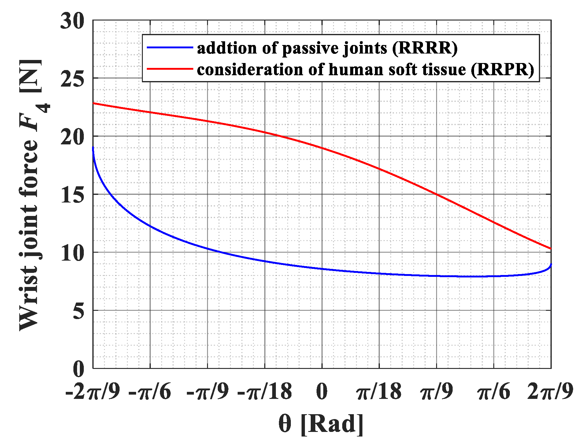
2.2. Addtion of Passive Joints

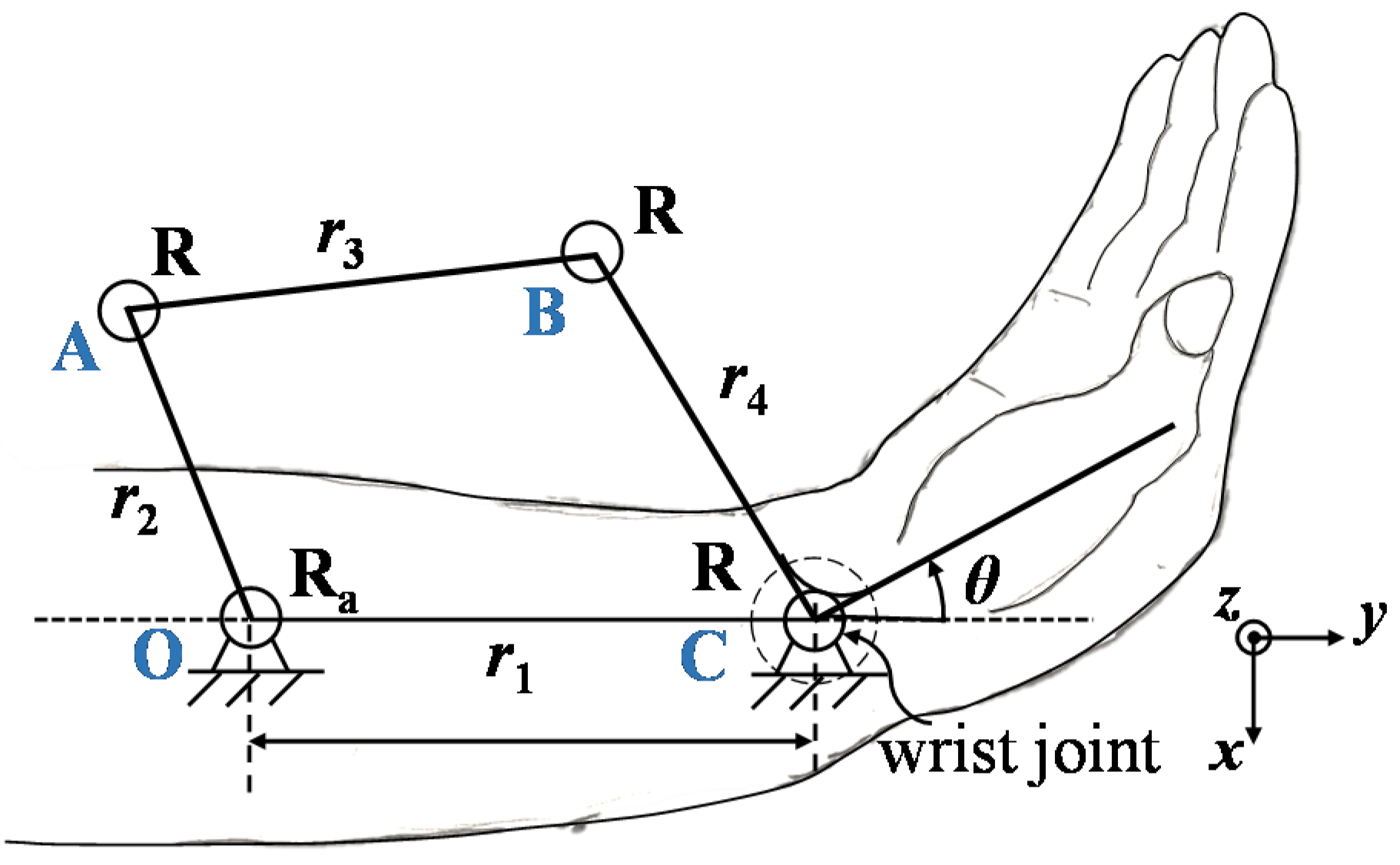
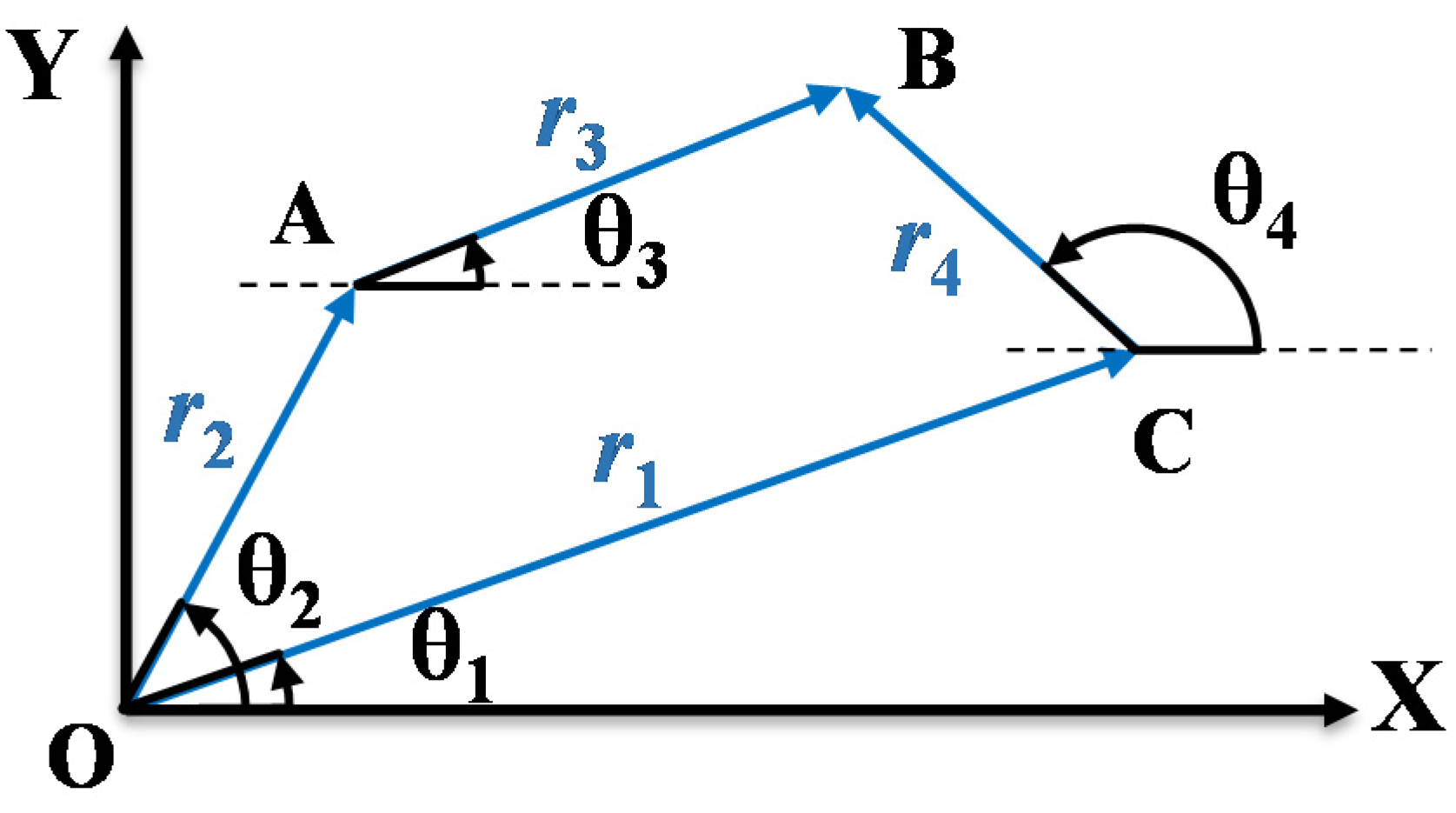
2.2.1. Four-Bar Linkage Design

Although it may increase the size and weight of the exoskeleton, it has been proved that adding passive joints to the robot is an effective solution to compensate for the misalignment of human–robot joints [13,14]. Inspired by these studies, in order to achieve a more compact design and lower friction mechanism, we intend to use revolute joints instead of prismatic joints as passive joints. The analytical model of the RRRR four-bar linkage is depicted in Figure 3. Here, as illustrated in Figure 4, three passive revolute joints were applied to form a planar four-bar linkage, where R and Ra denote revolute and active revolute joints, respectively. Through Gruebler’s equation, we can determine the degree of freedom (DOF) of the mechanism as follows:
F = λ ( n 1 j ) + i = 1 j f i
where λ is the DOF of the motion space, n is the total number of links, j is the total number of joints, and fi is the DOF of each joint. Once the exoskeleton is connected to the forearm as seen in Figure 4a, the human wrist is viewed as a virtual revolute joint to form a closed chain. By substituting λ = 3, n = 4, and j = 4 into Equation (6), it yields that the DOF of the mechanism is one. This means that the rehabilitation of the wrist joint can be achieved by the single input of the active revolute joint of this mechanism regardless of the dimensions of the mechanism. Therefore, this mechanism can be adapted to the position of the rotation axis of the wrist joint. In other words, this fact can be explained by considering the situation of the detachment of the exoskeleton from the human forearm depicted in Figure 4b. In this situation, the mechanism becomes an open chain and its DOF becomes three, which is the maximum DOF of planar mechanisms. Therefore, the distal link BC of this mechanism can be attached to the hand at an arbitrary pose (within the reachable area).
Next, the length of each link of the crank-rocker four-bar linkage can be determined by geometric analysis. In Figure 5, the rotation angle range (Δθ) for the output rocker link (r4) is given as 80 degrees (−40° to 40°) for wrist flexion-extension motion. By using the Equation (7) below, we can realize that, if the lengths of the fixed link r1 and actuated link r2 are known, the lengths of the coupler link r3 and the rocker link r4 can be obtained for the given rotation angle. As we know, the link lengths of the four-bar linkage would have a huge impact on the static performance of the mechanism. Thus, the optimization should be done to obtain the optimal link lengths, which will be discussed later in Section 2.2.3.
r 3 = r 1 r 2 s i n ( · θ 2 ) r 4 ,           r 4 = r 2 2 r 1 2 1 r 1 2 r 2 2 s i n 2 ( · θ 2 )

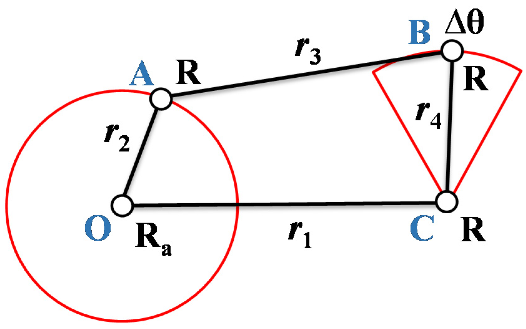
2.2.2. Kineto-Static Analysis
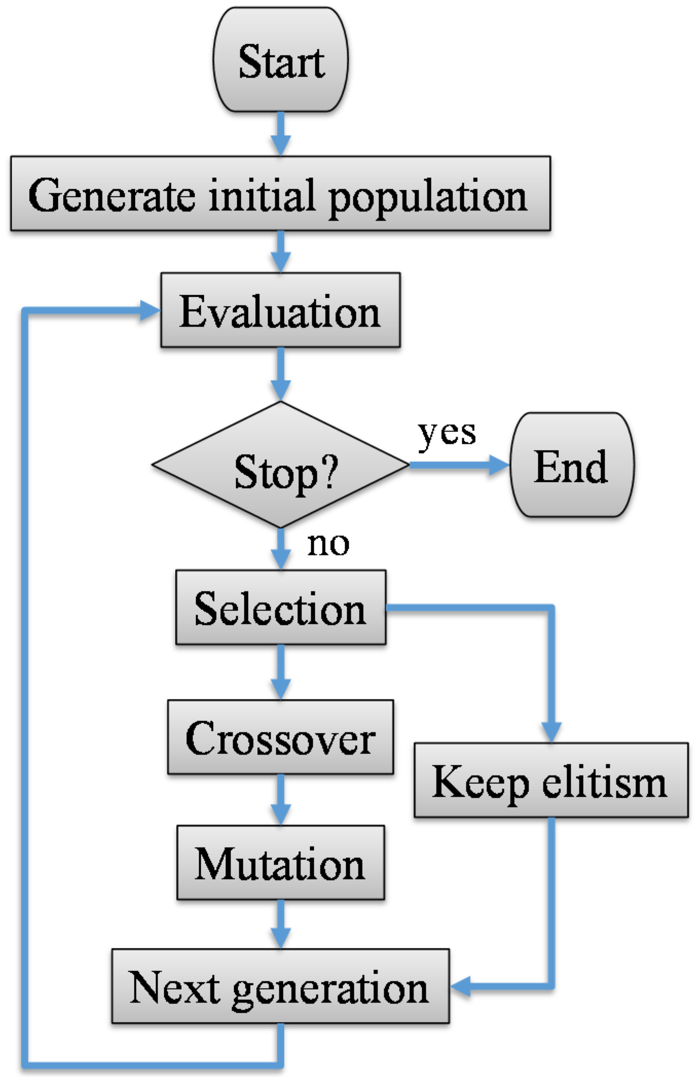
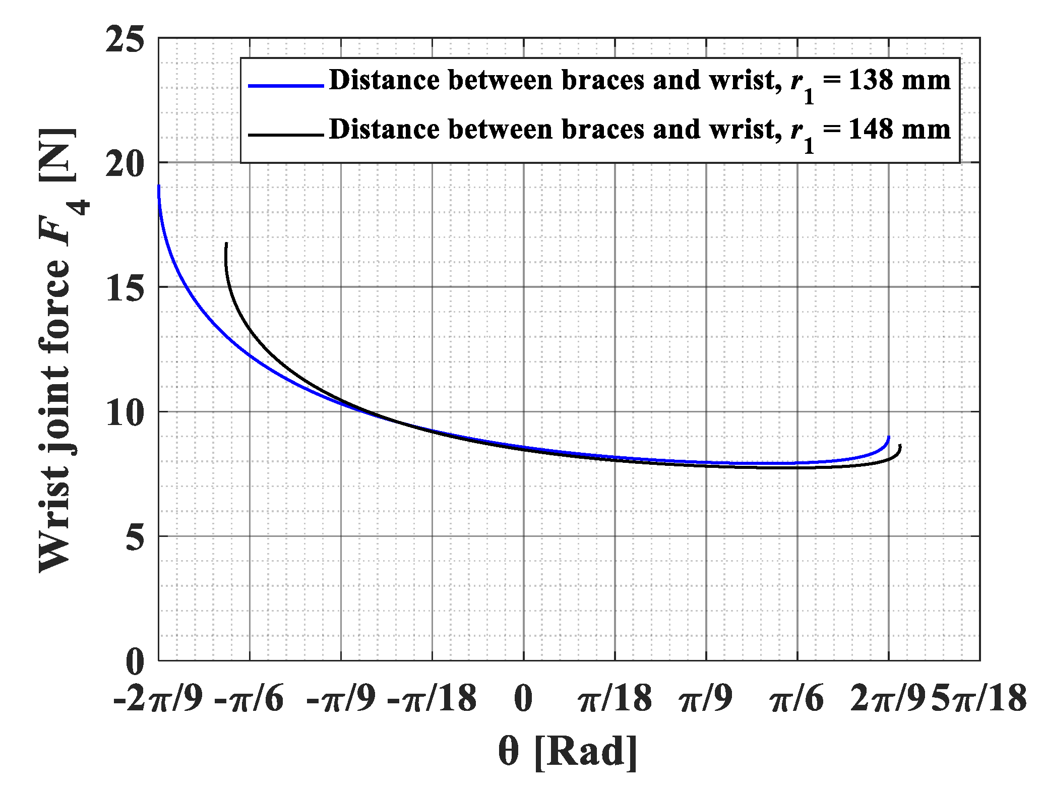
For the four-bar linkage geometry displayed in Figure 6, a vector-loop equation is written as follows:
r 2 + r 3 = r 1 + r 4
where each vector represents each link. We can also express Equation (8) in polar form as follows:
r 2 e j θ 2 + r 3 e j θ 3 = r 1 e j θ 1 + r 4 e j θ 4
By introducing complex numbers for each vector, Equation (9) can be written as follows:
r 2 ( cos θ 2 + j sin θ 2 ) + r 3 ( cos θ 3 + j sin θ 3 ) = r 1 ( cos θ 1 + j sin θ 1 ) + r 4 ( cos θ 4 + j sin θ 4 )
Next, Equation (10) can be separated into its real and imaginary components.
r 3 cos θ 3 = r 1 cos θ 1 + r 4 cos θ 4 r 2 cos θ 2
r 3 sin θ 3 = r 1 sin θ 1 + r 4 sin θ 4 r 2 sin θ 2
Now, square both sides of Equations (11) and (12) and then add them as follows:
r 3 2 = r 1 2 + r 2 2 + r 4 2 + 2 r 1 r 4 ( c o s θ 1 c o s θ 4 + s i n θ 1 s i n θ 4 ) 2 r 1 r 2 ( c o s θ 1 c o s θ 2 + s i n θ 1 s i n θ 2 ) 2 r 2 r 4 ( c o s θ 2 c o s θ 4 + s i n θ 2 s i n θ 4 )
To simplify the expression of Equation (13), the constants A, B, and C are defined as follows:
A = 2 r 1 r 4 c o s θ 1 2 r 2 r 4 c o s θ 2 B = 2 r 1 r 4 s i n θ 1 2 r 2 r 4 s i n θ 2 C = r 1 2 + r 2 2 r 3 2 + r 4 2 2 r 1 r 2 ( c o s θ 1 c o s θ 2 + s i n θ 1 s i n θ 2 )
and Equation (13) becomes the following:
Acos θ 4 + B s i n θ 4 + C = 0
Then, θ3 and θ4 can be solved with the universal trigonometric substitution for given θ1 and θ2.
θ 4 = 2 tan 1 ( B ± ( B 2 C 2 + A 2 ) 1 2 ( C A ) ) , π θ 4 π
θ 3 = tan 1 ( r 1 s i n θ 1 + r 4 s i n θ 4 r 2 s i n θ 2 r 1 c o s θ 1 + r 4 c o s θ 4 r 2 c o s θ 2 ) , π 2 θ 3 π 2
Next, in order to analyze the joint forces and required input torque to achieve the desired motion under the wrist joint torque, static force analysis has been carried out based on the above position analysis. The free body diagram of the linkage for this analysis is shown in Figure 7. According to several biomechanical studies of the activities of daily livings, the maximum torque for hand flexion/extension motion is about 0.35 N∙m [5,6]. For patients in need of rehabilitation, however, their joints are usually more resistant to joint movements related to injury, inflammation and so on. Hence, the output torque (Tout) is set as 1.2 N∙m in this research. We assume that, due to the low speed of the links, no inertia force is applied. Then, the equilibrium equations of each link can be put into a matrix as follows:
[ 1 0 1 0 0 0 0 0 0 0 1 0 1 0 0 0 0 0 0 0 a b 0 0 0 0 1 0 0 1 0 1 0 0 0 0 0 0 0 1 0 1 0 0 0 0 0 0 0 c d 0 0 0 0 0 0 0 1 0 1 0 0 0 0 0 0 0 1 0 1 0 0 0 0 0 e f 0 0 0 ] [ F 1 x F 1 y F 2 x F 2 y F 3 x F 3 y F 4 x F 4 y T i n ] = [ 0 0 0 0 0 0 0 0 T o u t ]
The unknowns are kept on the left-hand side and the known output torque (Tout) is on the right-hand side. These nine unknowns can be solved by Equation (17).

2.2.3. Optimization

As mentioned earlier, determining the length of links would have a significant impact on the static analysis, the details are shown and discussed later. In this section, the genetic algorithm (GA) proposed by Holland et al. [15] is used for the optimization of the link length. The GA is an optimization method inspired by evolution for seeking the maximum or minimum value of a given objective function f ( x ) , where x = { x i | i = 1 ,   2 ,   ,   N } . Through inheritance, selection, mutation, and crossover processes, it can generate solutions to avoid falling into local optimal solutions. To put it another way, it shows great promise in obtaining the global optimal solution. This feature is the main reason why we choose this approach for optimization. For our objective function, we want to find the length of each link when the minimum average force is applied on the wrist joint when the rotation of the wrist (θ) varies from −40° to 40°. In addition, considering the weight and portability of the device, we try to limit the size of the rehabilitation robot. For this purpose, each link length is restricted to not exceed the length of the r1 link. The average length of the human forearm between the elbow and the wrist is 274.33 mm [16]. We leave a certain distance between the location of braces and the elbow; therefore, the maximum link length constraint is set as 200 mm in the optimization. The optimization problem is expressed in the following statement:
minimize   f ( x ) = 1 N i = 1 N F w r i s t , i ( x )   subject   to   0 < l n 200 ,         n = 1 ,   ,   4
where N is the number of calculations and Fwrist is the force applied on the wrist obtained through each calculation. Since the number of variables used for optimization is two (r1 and r2), we set a population size as 70, which follows the rule for a general case that the population size is more than 10 times the of number of variables. Moreover, with the 40-bit length of one variable, we can ensure the higher accuracy of solutions. Furthermore, the typical values of crossover rate are in the range 0.5–1.0, and the common values of mutation rate are in the range 0.005–0.05 [17]. Therefore, we set the crossover rate and mutation rate as 0.7 and 0.02, respectively. The flowchart of optimization process is seen in Figure 8, and the selected GA parameters are displayed in Table 1.
After one thousand times of genetic generation, we can obtain the optimal length of each link. The optimal link lengths and the constant values of parameters used in analysis are listed in Table 2.

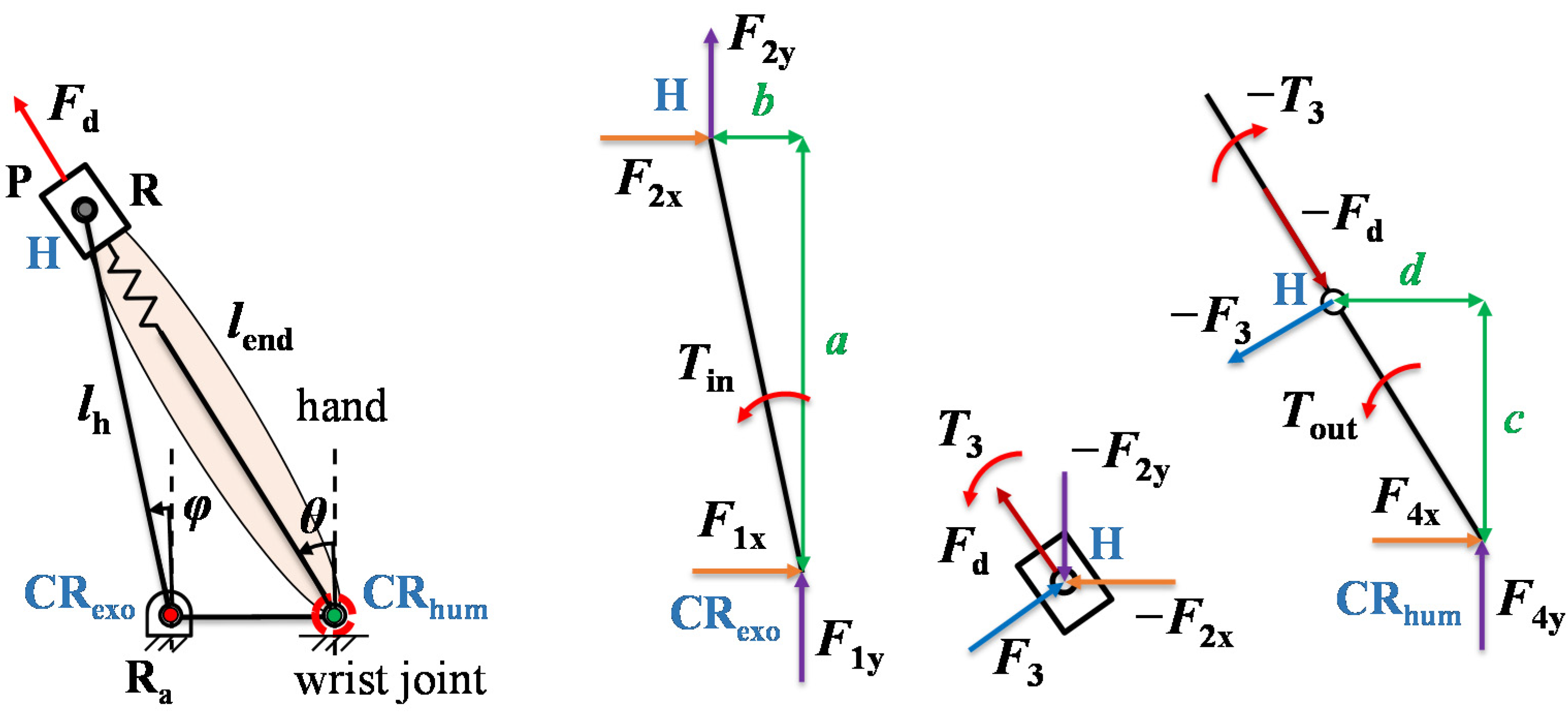
2.3. The Consideration of Human Soft Tissue

If we consider the similar concept of the analytical model mentioned in Section 2.1, we can use the same output torque and wrist rotation angle conditions to analyze the joint force of the mechanism. Although we have not added any actual passive joints to this mechanism, we can still treat it as a four-bar linkage. Indeed, when we consider the displacement of the hand-attached point, we have regarded this moving part as a prismatic joint connected to a spring. Consequently, the movement of the prismatic joint should be related to the spring constant of the hand. Owing to various measurement conditions, the spring constant of the human hand could be varied [18] and it is adopted as 172.5 N/m here. Based on the above presumptions, the mechanism with the wrist joint can form an RRPR planar four-bar linkage. Similarly, we apply the free body diagram depicted in Figure 9 to calculate the joint forces. Then, we can write the equilibrium equations in the matrix form as follows:
[ 1 0 1 0 0 0 0 0 0 0 1 0 1 0 0 0 0 0 0 0 a b 0 0 0 0 1 0 0 1 0 cos θ 0 0 0 0 0 0 0 1 sin θ 0 0 0 0 0 0 0 0 0 1 0 0 0 0 0 0 0 cos θ 0 1 0 0 0 0 0 0 sin θ 0 0 1 0 0 0 0 0 c 2 + d 2 1 0 0 0 ] [ F 1 x F 1 y F 2 x F 2 y F 3 T 3 F 4 x F 4 y T i n ] = [ 0 0 0 F d sin θ F d cos θ 0 F d sin θ F d cos θ T o u t ]
where Fd is a spring force in a direction opposite to the displacement of hand-attached point H along with the human hand.
On the other hand, we further consider the effects of human soft characteristics throughout rehabilitation. It is important to notice that the soft tissue of the forearm will still move during the motion because of its soft properties. Even if the braces are tightly fastened and attached to the forearm, the migration cannot be avoided. Therefore, if force is applied to the braces, it will cause the braces to move. In short, the distance between the braces and wrist (r1) is varied. Firstly, we assume the maximum amount of forearm tissue expansion to be 10 mm. So, if the force is exerted on the braces, the displacement of the braces would be 10 mm. Let us note that the displacement of the human forearm soft tissue is considered only in the direction along the forearm that aligns with y-axis direction in this paper. For simplicity, we ignore the linear displacement in other directions and the rotation of human soft tissue. Secondly, the concept of the dynamic pair is used, and we can view the forearm as having a spring-like behavior. The spring constant of the forearm is set as 143 N/m, as found in the literature [19]. Finally, we can perform position and force analysis to understand the impact of the human body’s softness properties. Although, this calculation cannot accurately predict the actual displacement of the attachment and only the maximum displacement (10 mm) is considered, the effect of the braces’ movement may now be discussed in a reasonable way. In Figure 10, Δs represents the displacement of braces, which changes during the movement. Hence, the length of the fixed link (r1) would become the following:
r 1 = r 1 ± Δ s

3. Results and Discussion

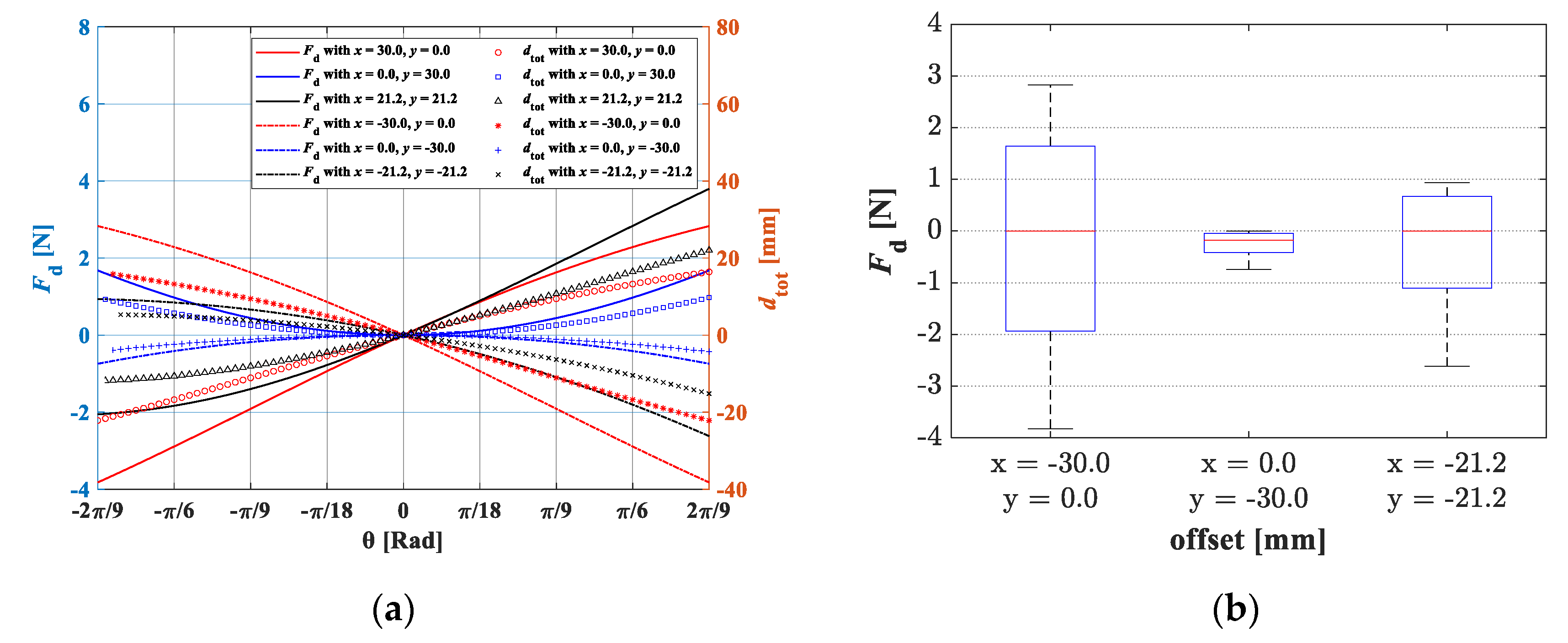
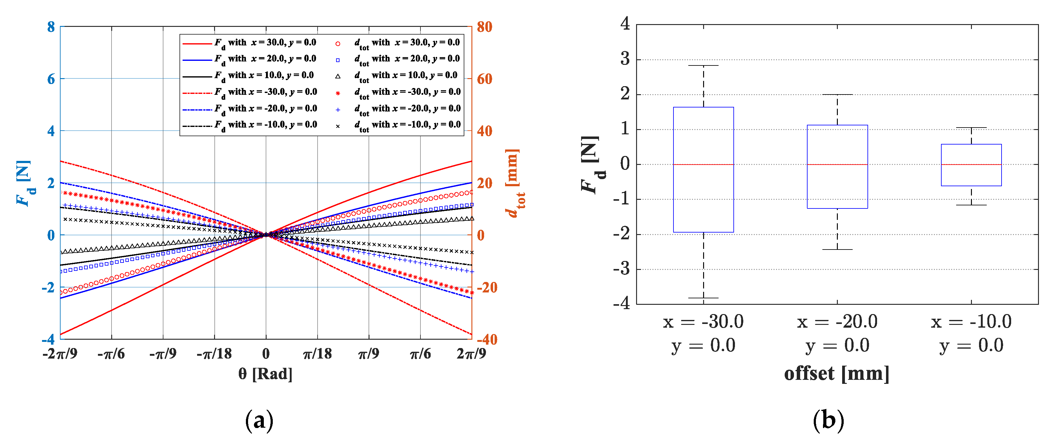
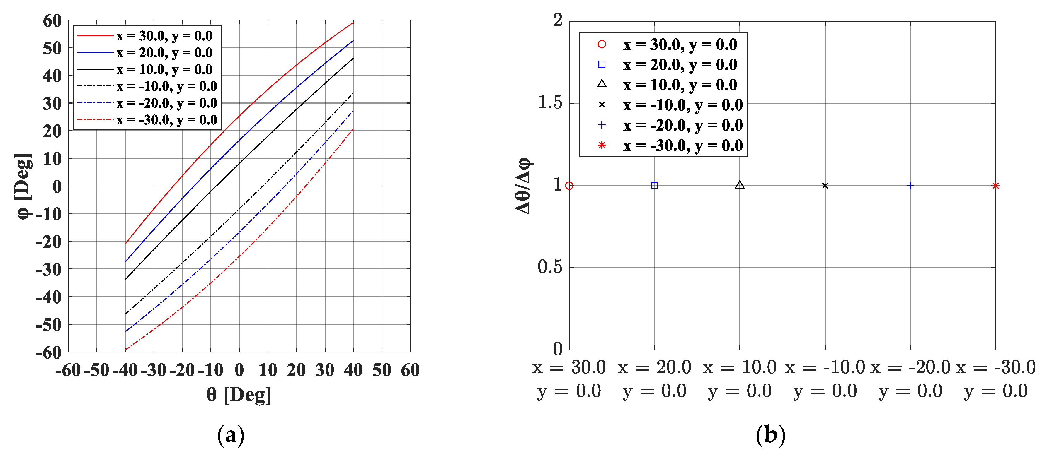
3.1. Static Force Analysis of a Wrist Rehabilitation Robot

In this section, we focus on the RRPR mechanism. The discussion of outcomes is addressed in two parts as follows: (1) offset influences; (2) compliance effects. Firstly, if the human joint and robot joint are not properly aligned, the offset may exist. We want to know how these existing offsets can have potentially adverse effects on rehabilitation. For this propose, it is assumed that the mechanism does not have any compliant components; therefore, only the hand is considered to comply with its spring constant as 172.5 N/m. Moreover, the hand link (lh) shown in Figure 2a is set as 70 mm and the offset is assigned as 30 mm in six directions. More precisely, the offset lies in the x direction, y direction and at an angle of 45 degrees to the x direction with both the positive and negative directions. Figure 11a shows the results of each case and the comparisons of the results are seen in Figure 11b. The analysis of the unwanted force reveals that the effect of the x direction offset is greater than in other cases, whereas the offset in the y direction has only a slight impact. This implies that, when a larger x-direction offset exists, it generates a larger displacement of the attachment along with the human hand (dtot), leading to a larger unwanted force. In order to improve the user’s comfort, more attention should be paid to the reduction of the x-direction offset. Moreover, Figure 12a demonstrates the proportionality of the offset magnitude and unwanted force. A clear trend can be found in both the positive and negative directions of the x-axis. In Figure 12b, we can see that increasing the initial offset results in a greater unwanted force. It is evident that a larger initial offset causes an increased displacement of the hand-attached point and producing a larger unwanted force. Consequently, the offset should be as small as possible, which only produces an unwanted force within the allowable range to prevent patients from feeling uncomfortable during rehabilitation. We further examine the rotation angle of the hand link (lh) with the offsets in various magnitudes and directions. It can be observed from Figure 13 that, although the beginning and the end angles of the hand link have changed, the total rotation angle is not influenced by the offset in the x direction in all cases. However, as we can see from Figure 14, a larger rotation angle range of the hand link results from a larger offset in the positive y direction. On the contrary, a smaller motion range of hand link can be found due to a larger offset in the negative y direction. These results indicate that if there exists an offset in the y direction, more attention should be paid to the range of motion of the hand link changes.
In addition, the use of different spring constant of compliance elements combining the human hand as a series spring set was considered. The results are given in Figure 15a, and we can see that the unwanted force varies depending on the total spring constant (ktot) of the hand with compliance. From Figure 15b, it can be observed that a larger spring constant causes a larger unwanted force. These results are in line with our expectation according to Equation (1) that the unwanted force increases with the total spring constant (ktot). Compared to the case without compliance, the maximum unwanted force is reduced to 38% while the softest compliance (ktot = 106.7 N/m) is used.

3.2. Addition of Passive Joints and the Consideration of Human Soft Tissue

In this section, we discuss the results of kineto-static analysis and evaluate the force applied on the wrist in different conditions. Using the methods described previously, the outcomes are presented into two parts: (1) comparison between the addition of passive joints and the consideration of human soft tissue; (2) the effects of the forearm’s softness during motion. It is important to notice that our analyzed target is right-handed, and the analysis is accomplished during the flexion motion of the right hand. In other words, the angle of the hand, θ, varies from −40° to 40°. For the first part, the same output torque (Tout = 1.2 N∙m) is applied for the cases of the addition of passive joints into the exoskeleton, and the soft characteristics of the human body are taken into account for joint misalignment compensation. The force acted on the wrist joint can be seen from Figure 16. The difference between the maximum and minimum wrist forces is not obvious in both cases, while, for the addition of the passive joint case, the average wrist force is less. The reason for the results may be thought to be that the displacement caused by the softness of the hand can also be considered as an addition of a prismatic joint into the robot. Therefore, this seems to provide the first evidence that we may model human soft tissue as one passive joint in robot design.
Secondly, we verify the effectiveness of the characteristics of the human soft tissue on an exoskeleton during rehabilitation. As mentioned, we consider that the displacement of braces exists; however, only the maximum displacement of the braces is considered. From Figure 17, we can observe that if we consider that the braces can move, the wrist force decreases from 19.10 to 16.79 N. It may be reasonable to suppose that considering the characteristics of human soft tissue, the braces become equivalent to the addition of compliance, which results in a relatively small wrist force. In simpler terms, part of the force is absorbed by the soft human part. Moreover, the distance between braces and wrist changes due to the movement of the braces, so that the angle range of the wrist also changes from 80° to 73.75°. It is apparent that only one link length changes while the other rigid links remain unchanged. Moreover, the range of the output angle should change. Consequently, from the results, we can say that the impact of human soft tissue cannot be ignored in robot design.

4. Conclusions and Future Work

Unlike many rehabilitation devices, which rely on manual adjustment for joint misalignment, the use of compliance and the addition of passive joints have been separately discussed in this research. Kineto-static analysis on a wrist rehabilitation robot has been performed, providing valid and feasible ideas for designing a safer and comfortable rehabilitation robot. (1) The effects of offset between human and robot joints in various directions and magnitudes are studied. The x-direction offset produces a larger unwanted force, while the y-direction offset has influenced the angular range of hand link. In addition, the use of compliance between human and robot aims to reduce an unwanted force. (2) The addition of passive joints is applied to compensate for joint misalignment, and we use the concept of the dynamic pair to model the human forearm for analysis. Our results show that if we consider the soft nature of the human body as a passive joint in the exoskeleton, the compensation for joint misalignment is similar. (3) Consideration of the characteristics of human soft tissues will cause the braces to move during the movement. This effect cannot be ignored in the design of wearable robots.
Although the 1-DOF robot analyzed in this research is relatively simple, we expect that the current discussion may further help extend the knowledge of joint misalignment compensation. With regards to future works, there are still some issues that should be considered in the design process. First, the robot should be designed to ensure human kinematic compatibility, for example, three DOF for the human wrist. Moreover, the acceptable limits of human parts’ movement need to be carefully investigated to avoid harmful effects to users. Finally, both the softness of the forearm and hand should be considered so that it can be more reasonably applied to practical applications.
Furthermore, a lightweight and portable rehabilitation device is still a long-standing demand. Taking into account the preliminary findings of the present paper, modeling human soft tissue as a passive joint in the exoskeleton may be a possible solution to further reduce weight and increase the compactness of the robot. We expect that these practical improvements will not only help to enhance safety and comfort, but also help to improve the portability of in-home rehabilitation.

Author Contributions

Conceptualization, Y.-C.L. and Y.T.; methodology, software, validation, formal analysis, investigation, writing-original draft preparation, Y.-C.L.; writing-review and editing, Y.-C.L. and Y.T.; visualization, Y.-C.L.; funding acquisition, project administration, supervision, Y.T. All authors have read and agreed to the published version of the manuscript.

Funding

This research was funded by Grant-in-Aid for Scientific Research of Japan Society for the Promotion of Science, grant number 17H03162, Japan.

Acknowledgments

This research was in part supported by Grant-in-Aid for Scientific Research of Japan Society for the Promotion of Science (17H03162), and by ABE TECHNO SYSTEM Co., Ltd.

Conflicts of Interest

The authors declare no conflict of interest.

References

  1. Maciejasz, P.; Eschweiler, J.; Gerlach-Hahn, K.; Jansen-Troy, A.; Leonhardt, S. A survey on robotic devices for upper limb rehabilitation. J. Neuroeng. Rehabil. 2014, 11, 3–31. [Google Scholar] [CrossRef] [PubMed] [Green Version]
  2. Molteni, F.; Gasperini, G.; Cannaviello, G.; Guanziroli, E. Exoskeleton and End-Effector Robots for Upper and Lower Limbs Rehabilitation: Narrative Review. PM&R 2018, 10, S174–S188. [Google Scholar]
  3. Norouzi-Gheidari, N.; Archambault, P.S.; Fung, J. Effects of robot-assisted therapy on stroke rehabilitation in upper limbs: Systematic review and meta-analysis of the literature. J. Rehabil. Res. Dev. 2012, 49, 479–496. [Google Scholar] [CrossRef] [PubMed]
  4. Ryu, J.; Cooney, W.P.; Askew, L.J.; An, K.-N.; Chao, E.Y.S. Functional Ranges of Motion of the Wrist Joint. J. Hand Surg. Am. 1991, 16, 409–419. [Google Scholar] [CrossRef]
  5. Pezent, E.; Rose, C.G.; Deshpande, A.D.; O’Malley, M.K. Design and characterization of the OpenWrist: A robotic wrist exoskeleton for coordinated hand-wrist rehabilitation. In Proceedings of the 2017 IEEE International Conference on Rehabilitation Robotics (ICORR), London, UK, 17–20 July 2017; pp. 720–725. [Google Scholar]
  6. McDaid, A.J. Development of an Anatomical Wrist Therapy Exoskeleton (AW-TEx). In Proceedings of the 2015 IEEE International Conference on Rehabilitation Robotics (ICORR), Singapore, 11–14 August 2015; pp. 434–439. [Google Scholar]
  7. Singh, N.; Saini, M.; Anand, S.; Kumar, N.; Srivastava, M.V.P.; Mehndiratta, A. Robotic Exoskeleton for Wrist and Fingers Joint in Post-Stroke Neuro-Rehabilitation for Low-Resource Settings. IEEE Trans Neural Syst. Rehabil. Eng. 2019, 27, 2369–2377. [Google Scholar] [CrossRef] [PubMed]
  8. Näf, M.B.; Junius, K.; Rossini, M.; Rodriguez-Guerrero, C.; Vanderborght, B.; Lefeber, D. Misalignment Compensation for Full Human-Exoskeleton Kinematic Compatibility: State of the Art and Evaluation. Appl. Mech. Rev. 2019, 70, 050802-1–050802-19. [Google Scholar] [CrossRef] [Green Version]
  9. Liu, Y.-C.; Takeda, Y. Static Analysis of a Wrist Rehabilitation Robot with Consideration to the Compliance and Joint Misalignment between the Robot and Human Hand. In Proceedings of the Annual Conference of the Robotics Society of Japan 2019, Tokyo, Japan, 3–7 September 2019. [Google Scholar]
  10. Liu, Y.-C.; Takeda, Y. Kineto-static Analysis of a Wrist Rehabilitation Robot with Compliant Elements and Supplementary Passive Joints to Compensate the Joint Misalignment. In Proceedings of the 25th Jc-IFToMM Symposium, 2nd International Jc-IFToMM Symposium, Kanagawa, Japan, 25–26 October 2019. [Google Scholar]
  11. Takeda, Y.; Sugahara, Y.; Matsuura, D.; Matsuda, S.; Suzuki, T.; Kitagawa, M.; Liu, Y.-C. Introduction of Dynamic Pair to Modeling and Kinemato-Dynamic Analysis of Wearable Assist-Devices. In Proceedings of the JSME Annual Mechanical Engineering Congress 2019, Akita, Japan, 8–11 September 2019. [Google Scholar]
  12. Schiele, A. An explicit model to predict and interpret constraint force creation in pHRI with exoskeletons. In Proceedings of the 2008 IEEE International Conference on Robotics and Automation (ICRA), Nice, France, 22–26 September 2008; pp. 1324–1330. [Google Scholar]
  13. Matsuura, D.; Ishida, S.; Koga, T.; Takeda, Y. Design of Ankle Rehabilitation Mechanism Using a Quantitative Measure of Load Reduction. Adv. Theory Pract. Robot. Manip. 2014, 22. [Google Scholar] [CrossRef]
  14. Szigeti, A.; Takeda, Y.; Matsuura, D. Portable design and range of motion control for an ankle rehabilitation mechanism capable of adjusting to changes in joint axis. Int. J. Mech. Robot. Syst. 2016, 3, 222–236. [Google Scholar] [CrossRef]
  15. Holland, J.H. Adaptation in Natural and Artificial Systems: An Introductory Analysis with Applications to Biology, Control, and Artificial Intelligence; U Michigan Press: Oxford, UK, 1975. [Google Scholar]
  16. Faghihi, A.; Haghpanah, S.A.; Farahmand, F.; Jafari, M. Design and fabrication of a robot for neurorehabilitation; Smart RoboWrist. In Proceedings of the 2nd International Conference on Knowledge-Based Engineering and Innovation (KBEI), Tehran, Iran, 5–7 November 2015; pp. 447–450. [Google Scholar]
  17. Srinivas, M.; Patnaik, L.M. Adaptive probabilities of crossover and mutation in genetic algorithms. IEEE Trans. Syst. Man. Cybern. 1994, 24, 656–667. [Google Scholar] [CrossRef] [Green Version]
  18. Gomi, H.; Koike, Y.; Kawato, M. Human hand stiffness during discrete point-to-point multi-joint movement. In Proceedings of the Annual International Conference of the IEEE Engineering in Medicine and Biology Society (EMBS), Paris, France, 29 October–1 November 1992; pp. 1628–1629. [Google Scholar]
  19. Yu, T.F.; Wilson, A.J. A passive movement method for parameter estimation of a musculo-skeletal arm model incorporating a modified hill muscle model. Comput. Methods Programs Biomed. 2014, 114, 46–59. [Google Scholar] [CrossRef] [PubMed] [Green Version]
Figure 1. Sketch of a wrist rehabilitation robot [9].
Machines 08 00023 g001
Figure 2. Analytical model of a robot with joint misalignment. (a) A model of a robot with misalignment; (b) the beginning of the movement process, at θ = 0; (c) the end of the movement process, at θ = θend.
Machines 08 00023 g002
Figure 3. Analytical model of RRRR four-bar linkage.
Machines 08 00023 g003
Figure 4. (a) Exoskeleton attached to the forearm; (b) Exoskeleton detached from the forearm.
Machines 08 00023 g004
Figure 5. Geometric analysis of four-bar linkage [10].
Machines 08 00023 g005
Figure 6. Vector loop of four-bar linkage [10].
Machines 08 00023 g006
Figure 7. Free body diagram of four-bar linkage.
Machines 08 00023 g007
Figure 8. Flowchart of genetic algorithm (GA).
Machines 08 00023 g008
Figure 9. Free body diagram of the wrist robot.
Machines 08 00023 g009
Figure 10. Model of four-bar linkage with compliance.
Machines 08 00023 g010
Figure 11. (a) Influences of the offset direction; (b) comparisons of offset direction.
Machines 08 00023 g011
Figure 12. (a) Influences of offset magnitude; (b) comparisons of offset magnitude.
Machines 08 00023 g012
Figure 13. (a) Relationship of θ and φ with the x offset; (b) comparison of θ and φ with the x offset.
Machines 08 00023 g013
Figure 14. (a) Relationship of θ and φ with the y offset; (b) comparison of θ and φ with the y offset.
Machines 08 00023 g014
Figure 15. (a) Effects of compliance elements; (b) comparisons of compliance elements.
Machines 08 00023 g015
Figure 16. Wrist force comparisons with the addition of passive joints (RRRR) and consideration of human soft characteristics (RRPR).
Machines 08 00023 g016
Figure 17. Wrist force comparisons with different distances between braces and wrist.
Machines 08 00023 g017
Table 1. Genetic algorithm (GA) parameters used in optimization.
Bit Length of One VariablePopulation SizeCrossover RateMutation Rate
40700.70.02
Table 2. The optimal and constant values of parameters used in analysis.
DescriptionParameterValueUnit
Optimal distance between braces and wrist jointr1138.0mm
Optimal length of crank linkr271.6mm
Optimal length of coupler linkr3199.8mm
Optimal length of rocker linkr4161.3mm
Spring constant of forearmk143N/m
Output torqueTout1.2N·m

