1. Introduction
The planetary gearbox is one of the most used mechanical transmission designs due to the advantages that it has over the gearbox with simple transmission, i.e., high torque, high transmission rate, high speed rate, compact volume design, to mention a few. However, planetary gearboxes are characterized by a complex kinematics and many internal and external excitation sources, such as varying mesh and bearing stiffness, assembly errors, manufacturing errors and varying operation conditions of speed and load. These excitation sources may increase the modal interaction in non-linear regimes and produce chaotic behavior, nonlinear jump, resonance and bifurcation. Therefore, there is a constant interest for modelling the dynamics of planetary gearboxes.
Modal analysis is a widely used technique to calculate the frequency response of a system and thus, determine the natural frequencies, modal damping, and the mode shapes. Experimentally, it is based on impact test and an excited mechanical structure by means of a hammer and a shaker, respectively. Nevertheless, it has been proved that experimental modal analysis suffers from missing modes because some modes cannot be excited [
1]. Numerous research works on condition monitoring and fault diagnosis have been accomplished with the aim of preserve planetary gearboxes in healthy operating conditions. Many of them have been focused on the analysis of the stationary operation process [
2,
3,
4]. However, stationary conditions may hide important transient features about the machinery condition that can be exposed only during non-stationary operation, especially during the run-up and run-down process [
5,
6].
Flexible and rigid body models have been developed by researchers with the aim of reproducing the dynamic behavior of planetary gearboxes, as well as developing fault diagnosis techniques. The effect of the elasticity of the ring gear on the modal properties and time varying mesh stiffness of a planetary gear system has been studied through the variation of design parameters, such as the number of planets, ring-bending stiffness and sliding friction coefficient in the dynamic model [
7]. The modulation sidebands induced by a single planet gear mesh and multiple planet gears meshes on the dynamic response of a planetary gear have been studied using models based on signal transfer path functions and measuring-direction projection functions of the gear mesh force. The analysis of the significance level of meshing frequency modulation can reveal important dynamic characteristics for failure identification [
8,
9] and even to distinguish whether the planetary gear train is assembled with a floating sun gear, or whether the planetary gear train without a floating sun gear exists with some distributed defects [
10].
The modulation phenomenon caused by the time-varying gear meshing and position of the planet gears is widely studied. Vibration signals at the transducer location are expressed by the sum of all vibrations induced from each component and influenced by the time-varying path [
11]. The geometry of the tooth profile has an important role in the gear meshing in planetary gear trains. Models based on the exact involute gear geometry have been proposed as a tool for the determination of tolerances for the movable area and assemblability of the sun gear, the backlash and other components of the gear train [
12]. It also has been demonstrated that the tooth wear has an important effect on the bending stiffness, shear stiffness, and axial compressive stiffness because they depend of the tooth profile and tooth thickness, and the time-varying mesh stiffness decreases according to the tooth wear depth [
13].
Accelerometers are the transducers mostly used to capture the dynamic behavior of rotating machinery. The location of the accelerometers on the gearbox structure plays an important role, especially in planetary gearboxes, which have multiple planets producing similar vibrations when the planets pass through the fixed sensor [
14]. On the other hand, even when there are experimental works that do not require angular information [
15,
16], tachometers are necessary to measure important variable speed conditions. Other transducers widely used are extensometers and thermocouples, since they allow to evaluate the performance efficiency and the energy loss during the torque transmission [
17].
In this context, this paper presents an experimental analysis of feasibility for a two-stage planetary gearbox (TSPG) prototype at the Laboratory of Robot Mechatronics (LARM2) in the University of Rome Tor Vergata, with the aim of validate its functionality and quantify its efficiency and dynamic behavior. Experiments are carried out in a test bed which allows to develop non-stationary operating conditions by means of varying the load torque and measuring multiple variables.
2. Gearbox Design
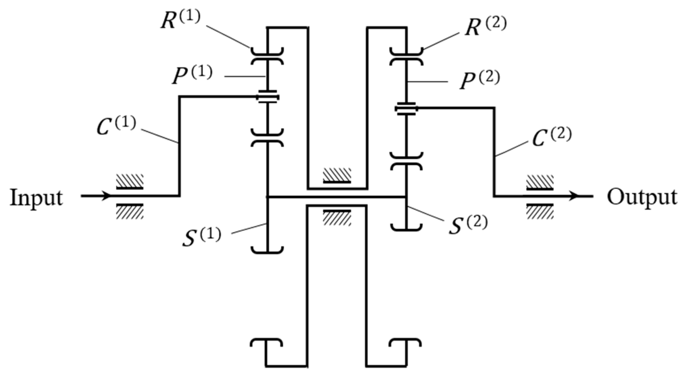
A schematic of the planetary gearbox under study is shown in
Figure 1 [
18]. It consists of two-stage planetary gear trains in parallel with floating sun gears. Each planetary train comprises one carrier
, two planet gears
, one sun gear
and one internal ring gear
; the superscript
indicates the corresponding planetary train,
for the input train and
for the output train. Note that since the sun gears are fixed on the same shaft and the ring gears are on the same frame, each couple of gears actuates as a rigid body,
and
. The input torque is applied to the sun gear
and ring gears
from the input carrier
by means of the planet gears
. Since sun gears and ring gears act like a rigid body, the torque is transmitted to the planet gears
to the output carrier
.
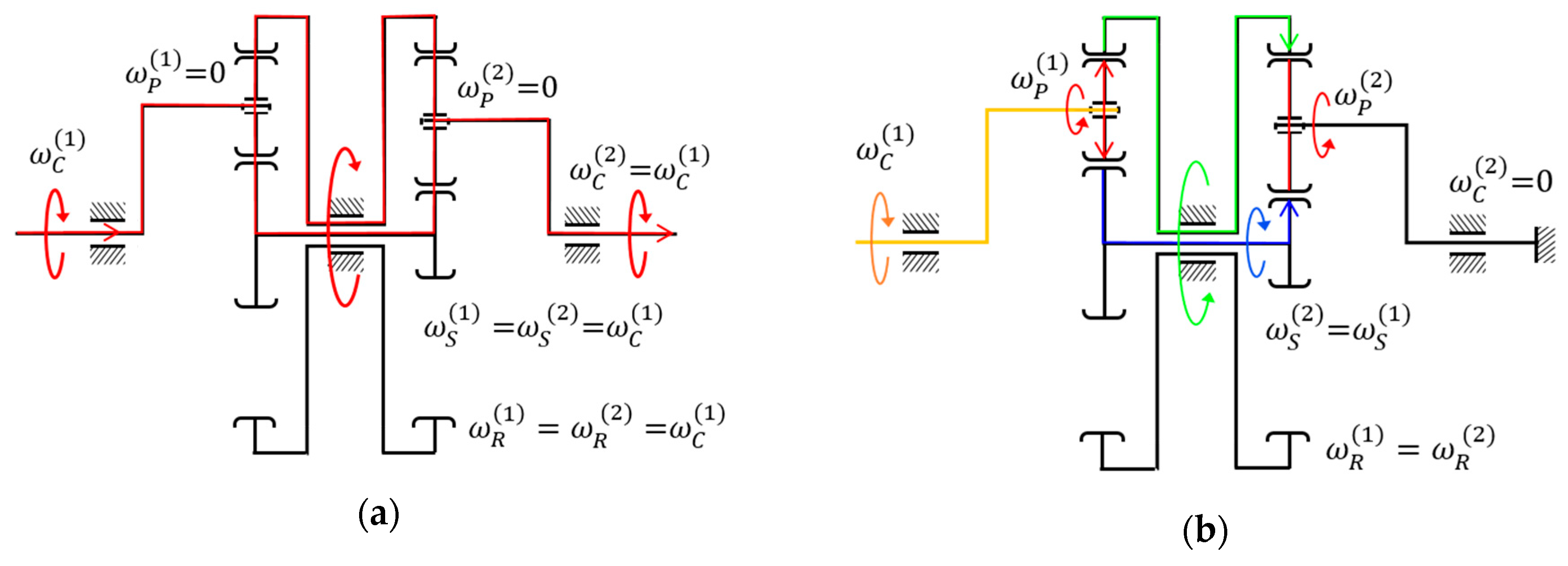
The TSPG mechanism operates differentially as function of the load torque and the internal friction forces that are caused by the contact between gears,
Figure 2. The first operation stage (FOS) of the planetary gearbox runs when the torque caused for the attached load is low,
Figure 2a. In this operating condition, the friction forces between gears cause a self-locking phenomenon that locks the planet gears to the sun and ring gears. As consequence, they do not rotate over their own axes,
. Consequently, the closed gear chain
-
-
-
-
-
behaves as a unique rigid body which rotates about the axis of the two sun gears. Thus, the movement of the input carrier is directly transmitted to the output carrier, giving
. The second operating stage (SOS) of the planetary gearbox runs when the load torque increases,
Figure 2b, and causes that the output carrier remains locked in a fixed position with
. Meanwhile the friction forces between gears are overcome and the planet gears start to rotate around their own axes with
. Consequently, the frame of the ring gears becomes the output link rotating in opposite direction to the input carrier.
The operational characteristics of the gearbox enable the self-exchanging of the output link under variable load conditions. Thus, when the load increases suddenly the actuation of the SOS helps to reduce the stress in the internal gearbox elements.
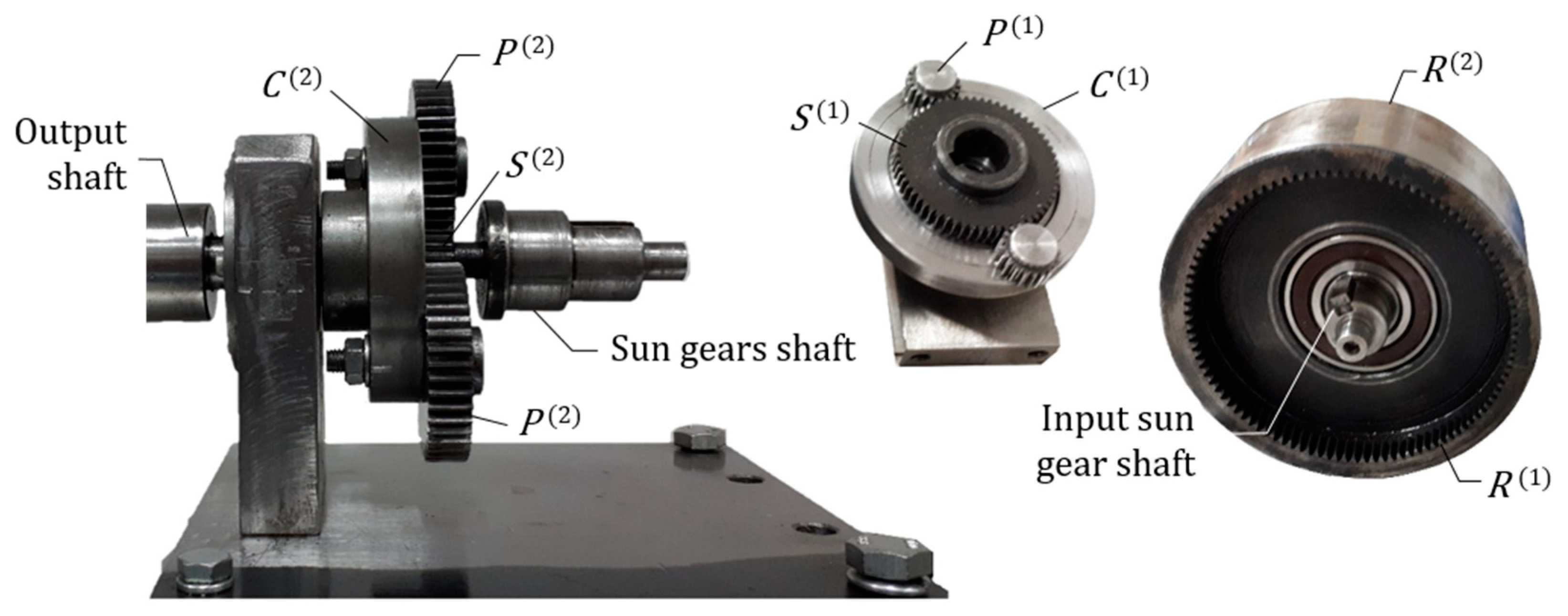
The prototype of the TSPG is shown in
Figure 3. All gears are spur gears with modules equal to 1 mm and pressure angle equal to 20°. The design parameters of the gears are listed in
Table 1.
The gear ratio
, for the input (
) and output (
) planetary gear trains in
Figure 1, can be expressed as function of the teeth number of the gears
and the angular velocity
of each element as follows:
By solving Equations (1) and (2), the angular velocity of the ring gear and the sun gear are given by
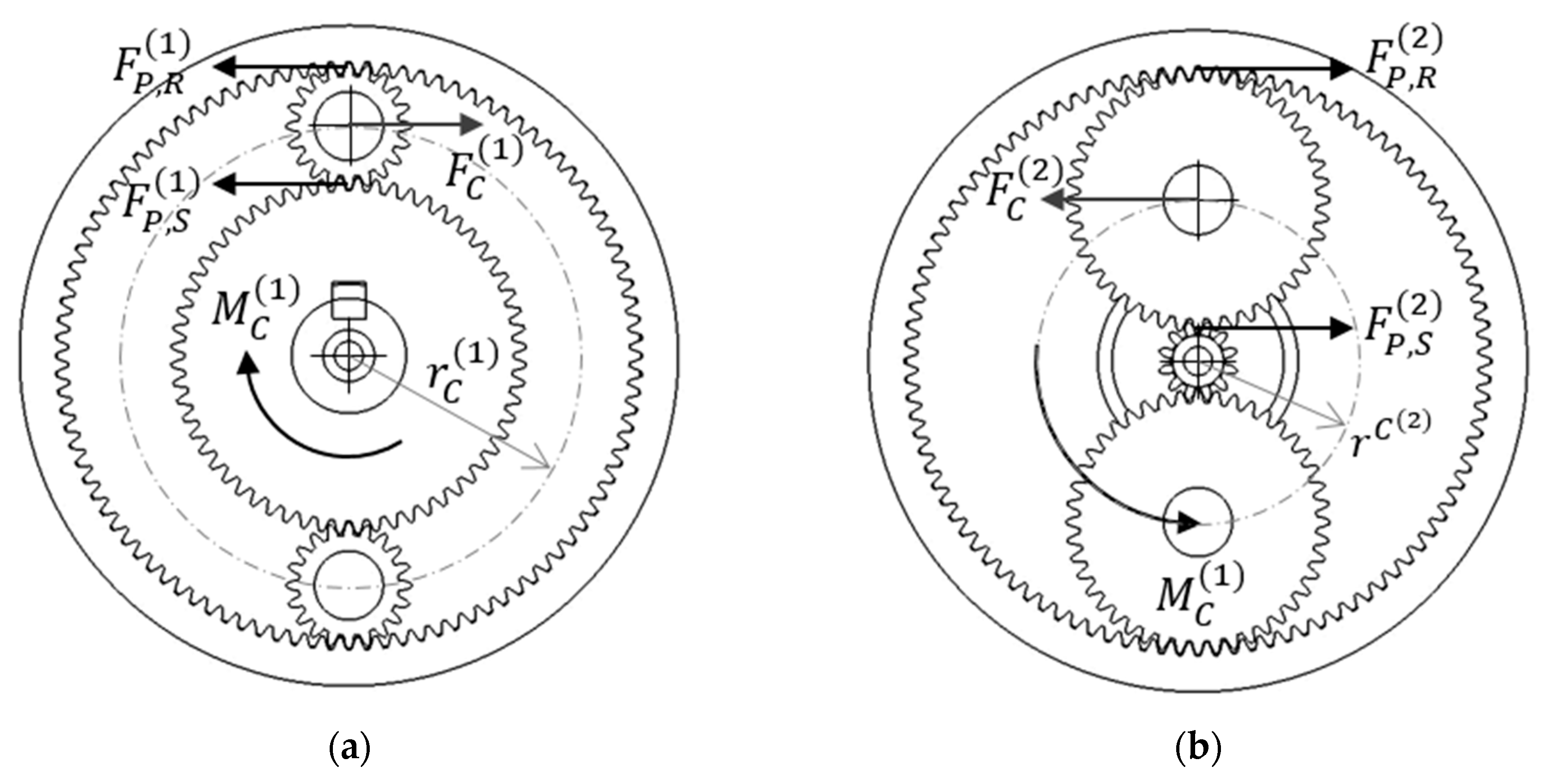
On the other hand, the torques transmitted for the planetary gearbox can be obtained from a static equilibrium analysis as shown in
Figure 4. Where,
and
are the transmitted force and the radius of the element
, respectively. Thus, the torques transmitted by the input and output carriers are given as:
Finally, the efficiency of the planetary gear train can be obtained by:
where,
is the mechanical power of the input and output gear trains,
respectively, given by:
3. Test-Bed Design
A new test-bed configuration was designed in order to characterize the dynamic performance of the two-stage planetary gearbox under study. However, the design characteristics of the test-bed enable the development of test of other rotating machinery with similar operating requirements. The test-bed was projected with the aim to test the full operation condition of the planetary gearbox prototype, meanwhile the most representative dynamic variables are measured.
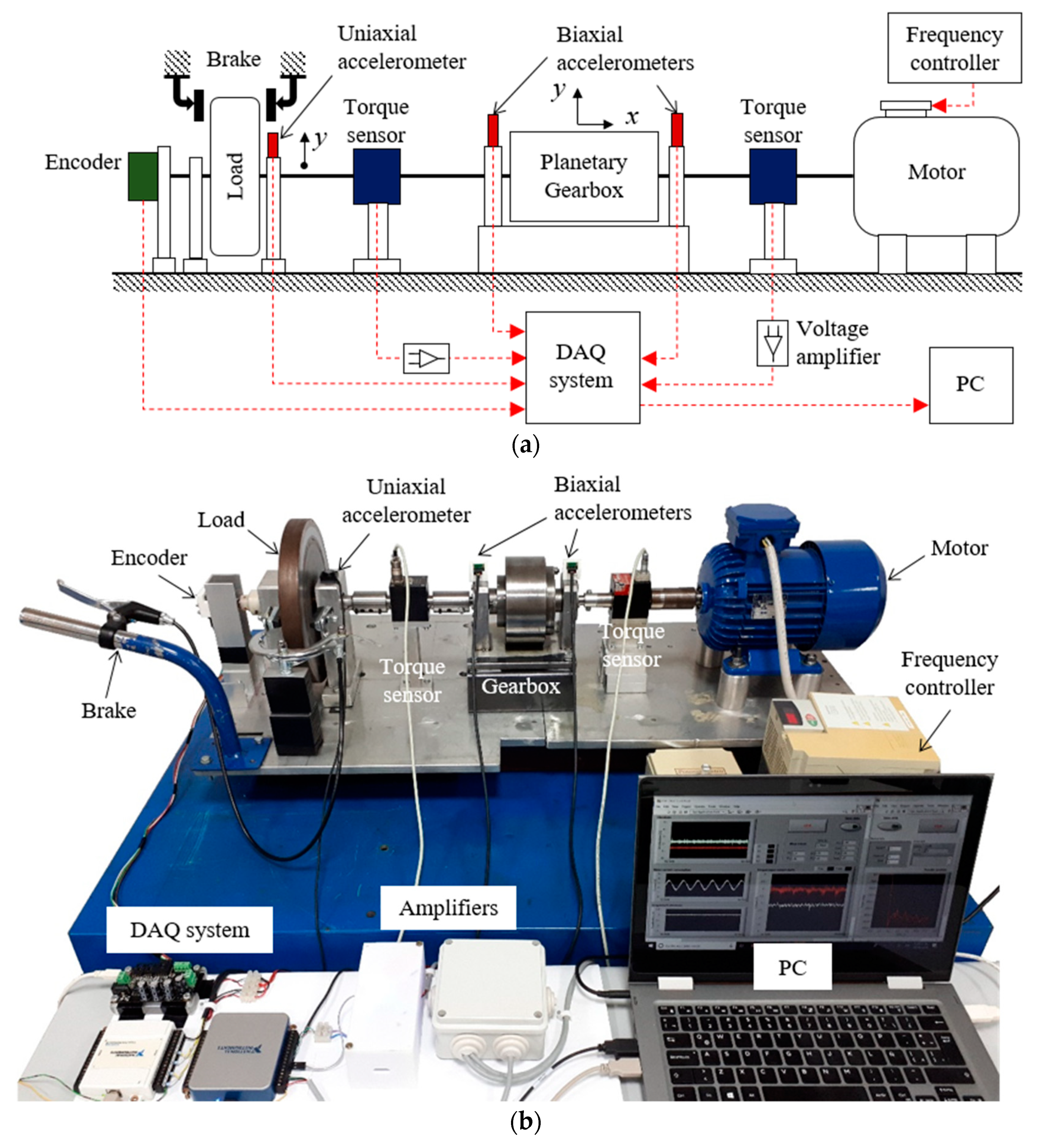
Figure 5 shows the schematic diagram and the experimental setup of the test-bed. It consists of an AC motor that is coupled to a planetary gearbox prototype to drive the attached load. The operating speed of the motor is controlled by means of a frequency inverter, while the load torque is variated by means of a mechanical break, which actuates directly on the load surface.
The test-bed is instrumented to measure the most representative variables for rotating machinery. Two biaxial accelerometers are placed on the bearings that support the input and output shafts of the gearbox, respectively, to measure the radial and axial vibrations. One uniaxial accelerometer is placed on the bearing that supports the output shaft near the load to measure the radial vibrations; as indicated in
Figure 5. Two dynamic torque sensors are placed in the input and output shafts of the gearbox, respectively, to measure the torque variation during the exchange between the FOS and SOS. Finally, one encoder is placed in the output shaft to measure the angular velocity.
The data acquisition system consists of a signal conditioning stage to amplify the torque signals, two DAQ boards from National Instruments and one DAQ board from Phidgets Inc. The development of the tests is supervised by means of a graphical user interface developed in LabView. Furthermore, from the user interface it is possible to control the acquisition of data, the sampling frequency and the data storage in the PC. The list of the equipment installed in the test-bed is given in
Table 2.
The test-bed enables the development of different kind of tests, such as: (1) run-up and run-down speed profile tests, (2) constant operating speed and constant load, (3) varying operating speed and varying load. In this work, the experience with the TSPG prototype is reported at constant operational speed and varying load.
4. Experimental Results
Experiments are carried out at constant speed and varying load. The results for the two different speed conditions = 120 rpm and = 210 rpm are presented in this work; where indicates the nominal speed that the motor drive reaches. The load condition is variated during the experiments from low to high by means of brake system actuation. The term low load refers to the load condition produced by the single flywheel, while the term high load refers to the load condition produced when the brake actuates on the flywheel surface.
Each experiment is conducted as follows: (1) the system is started up with low load condition; therefore, the FOS of the TSPG is actuated; (2) when the output shaft reaches the nominal speed , the load is increased; consequently, the SOS of the TSPG is actuated; (3) when the system reaches the nominal operating conditions, the load is decreased; thus, the FOS of the gearbox is reactivated. Experimental results are presented below in order to analyze the dynamics of the gearbox during the operational exchange between FOS and SOS.
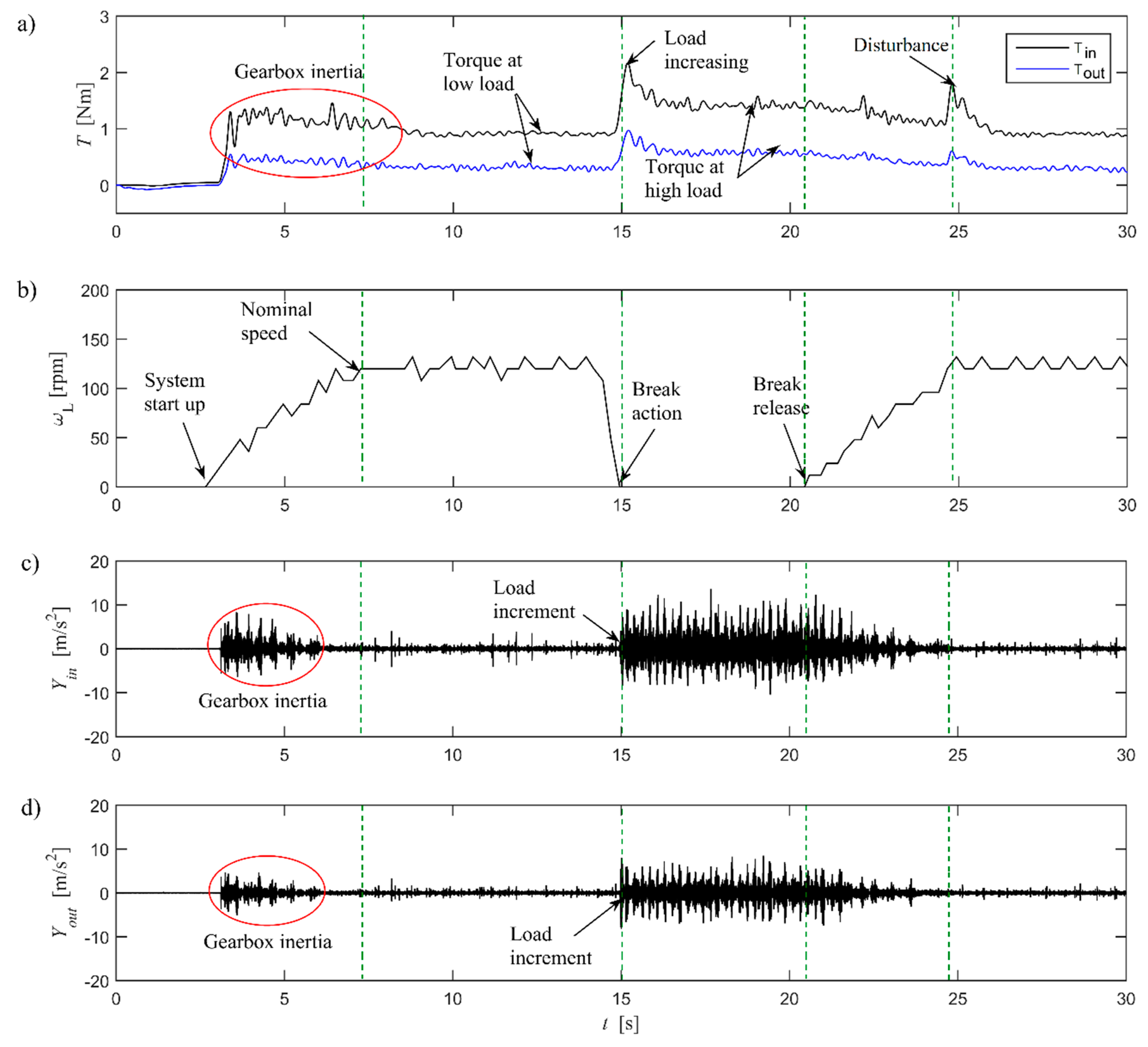
Figure 6 shows the experimental results for the test at
= 120 rpm. It can be seen that the amplitude of the torques and vibrations varies as a response of the load variation. The dynamic torques in the input and output shafts are shown in
Figure 6a. It can be seen that both input and output torques have similar behavior. The torque amplitudes increase as the load increases and they decrease as the load decreases. However, the input shaft torque is always higher than the output shaft torque. This is because the torque in the input shaft is imposed by the torque in the output.
Figure 6a shows that the input and output shaft torques increase during the start-up of the system until they reach the maximum values
= 1.38 Nm and
= 0.54 Nm, respectively. This increment is produced by the inertial mass of the coupled system gearbox-load. Once the inertial mass is overcome, the coupled system starts to rotate and the torques decrease until they reach nominal values under low load condition,
= 0.94 Nm and
= 0.30 Nm.
The high load condition in the output shaft is generated by means of the actuation of the brake system,
Figure 6b. As consequence, a sudden increment in the torques arises, with peak values
= 2.17 Nm and
= 0.97 Nm. Then, the SOS of the gearbox is self-actuated and the torques decrease until they reach the nominal values under high load condition,
= 1.41 Nm and
= 0.56 Nm. It is important to note that the nominal values of the torques under high load condition are higher than those under low load condition. This is because the higher the load, the higher the input torque to drive it.
The usefulness of the SOS in the gearbox design can be seen as the reduction of the torque in the gearbox elements once the system achieves stable operation under high load condition. Thus, in this work, the torque reduction is estimated as the difference between the peak value of the torque when the load increases and its nominal value after the system achieves the stable operation condition. From the experimental data at = 120 rpm, it is estimated that the actuation of the SOS of the gearbox enables the reduction of torque 57% in the output shaft and 65% in the input shaft.
After the stable operation condition with the SOS is achieved, the load torque is decreased and the FOS of the gearbox is reactivated. It can be seen in
Figure 6a that the torques decrease smoothly until they reach again the nominal values under low load condition. A disturbance in the torque signals appears when the output shaft reaches the nominal speed
= 120 rpm. This disturbance is produced by the self-locking phenomenon of the gears that occurs when the system achieves the nominal operation conditions for the FOS.
The small disturbances in the torque signals caused for the self-locking phenomenon of the gears when the system reach the nominal operation conditions for the FOS can be seen again in
Figure 7a.
The angular speed of the output shaft is shown in
Figure 6b. It can be seen that during the operation of the FOS, the rotation of the input shaft is directly transmitted to the output shaft, while during the operation of the SOS, the output shaft remains braked. It is important to note that the variations in the angular velocity measurements are due to the quality of the encoder used during the experiments.
The radial vibrations on the input and output shafts during the test at
= 120 rpm are shown in
Figure 6c,d, respectively. The vibrations at the beginning of the test are generated due to the overcoming of the inertial mass gearbox-load. Furthermore, it can be seen that the vibration amplitudes increase suddenly when the SOS is actuated and they decrease as the system reaches nominal operational conditions. It is assumed that the higher amplitudes of vibration in the input shaft than those in the output shaft are because the input carrier is rotating while the output carrier remains braked in a fixed position.
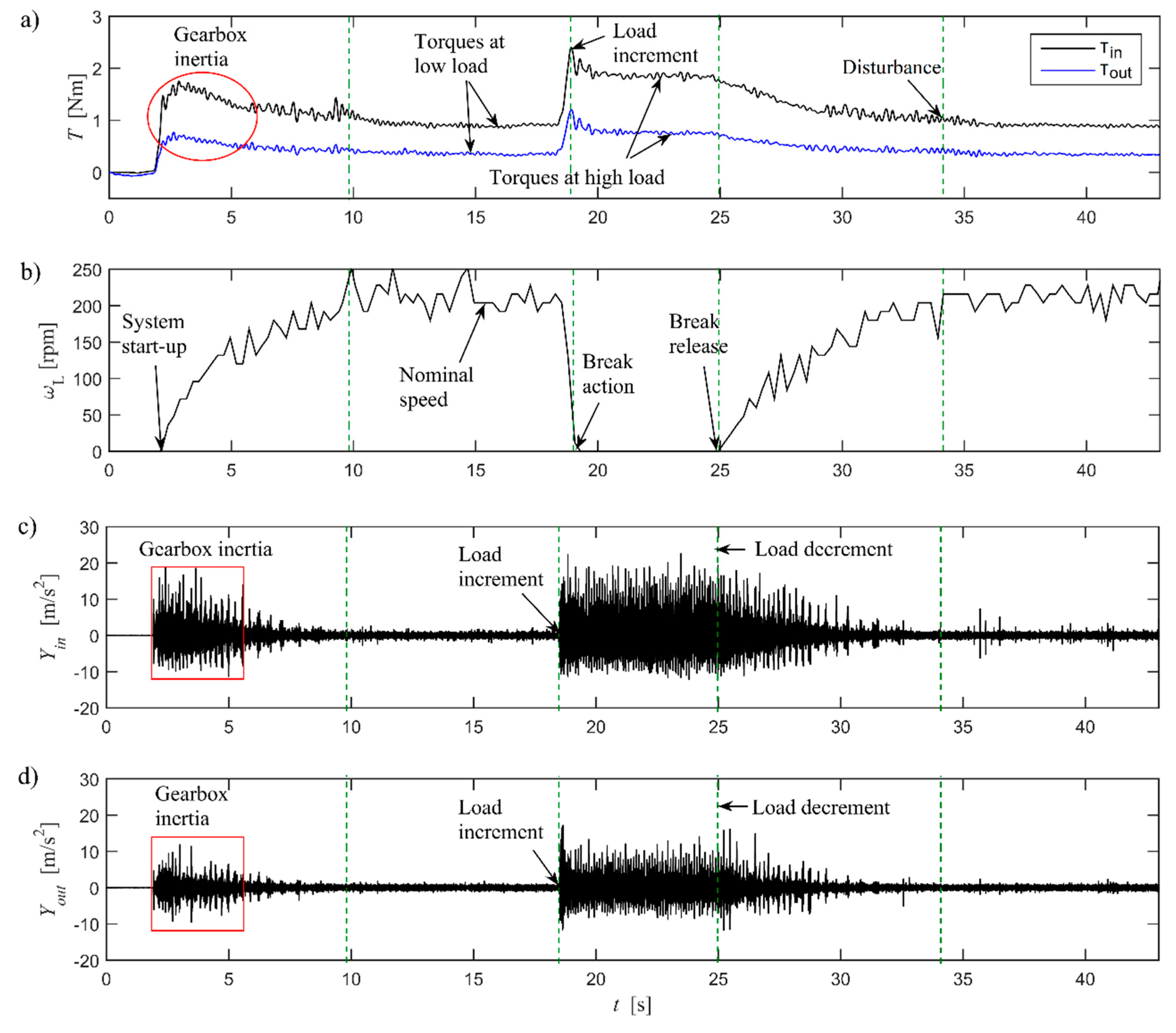
The experimental results for the test at
= 210 rpm are shown in
Figure 7. Similar to the previous experimental case, it can be seen that the amplitude of the torques and vibrations varies in response to the varying load condition. Their amplitudes are always higher in the input shaft than in the output shaft.
The torques in the input and output shafts are shown in
Figure 7a. It can be seen that their dynamic behavior is similar to that of the previous test. The maximum amplitude of the torque caused for the inertial mass gearbox-load during the system star-up are
= 1.75 Nm and
= 0.77 Nm. Once the inertial mass of the coupled system gearbox-load is overcome, the FOS of the gearbox starts to operate. The nominal torque values for the input and output shafts under low load condition are
= 0.89 Nm and
= 0.34 Nm, respectively. The SOS of the gearbox is actuated when the load increases. The maximum peak values of torques under high load condition are
= 2.40 Nm and
= 1.20 Nm. The torque amplitudes decrease as the system achieves the nominal operation conditions for the SOS. The nominal values of torques under high load condition are
= 1.83 Nm and
= 0.76 Nm. The reduction of torques during the operation of the SOS of the gearbox is estimated as described before. The reduction of torques for this test is 63% in the output shaft and 76% in the input shaft. The disturbance in the torque signals caused for the self-locking phenomenon of the gears that occurs when the system achieves the nominal operation conditions for the FOS can be seen again in
Figure 7a.
The angular speed of the output shaft is shown in
Figure 7b and the radial vibrations on the input and output shafts are shown in
Figure 7c,d, respectively. It can be seen that the vibrations increase during the overcoming of the inertial mass of the coupled system gearbox-load at the beginning of the test. Furthermore, it can be seen that the amplitude of vibrations increases suddenly when the SOS of the gearbox is actuated and also it increases at higher operational speed.
6. Conclusions
A new configuration of the test bed is presented in order to evaluate the dynamic behavior of a two-stage planetary gearbox (TSPG). The conceptual design of the test-bed enables the development of experiments on rotating machinery with similar operating requirements. In this work, experimental tests at constant operating speed and varying load are carried out in order to test the operation of the TSPG designed at LARM2.
The TSPG mechanism consists of a two-stage planetary gearbox in parallel with floating sun gears. The mechanism operates differentially as a function of the load torque and the internal friction forces that are caused by the contact between gears. The first operation condition (FOS) is self-actuated under low load conditions. The second operation stage (SOS) is self-actuated under high load conditions. The characteristics of the gearbox enable the self-exchanging of the output link under variable load conditions. The SOS enables the ring gear as the output link when the load in the output shaft increases suddenly. As a consequence, the stress in the internal gearbox elements is reduced under high load operation conditions.
The experimental results demonstrate the usefulness of the gearbox design since the SOS is self-actuated when the load in the output shaft increases suddenly. The high load condition of the gearbox produces a sudden increment in the amplitude of the torques. However, the torques decrease as the SOS achieves the nominal operation conditions. Thus, the actuation of the SOS reduces the stress on the gearbox elements. The results show that the actuation of the SOS reduces the torque 57% in the output shaft and 65% in the input shaft during the test at 120 rpm and 63% and 76%, respectively, during the test at 210 rpm. The efficiency, inertial mass of the coupled system gearbox-load and the friction torque in the internal gearbox components are estimated from the torque signals. It is found that the efficiency of the gearbox is ≈ 40%. This value is expected to be low since the lubrication of the gears is absent due to the missing housing of the gearbox. The inertial mass of the coupled system gearbox-load is estimated as 0.89 Nm and the friction torque generated by in the internal gearbox elements is 1.23 Nm.
Future work is planned for the modelling of the TSPG mechanism and the identification of parameters from vibration signals, such as the design modifications in order to improve the efficiency and to use the torque transmitted by the ring gear during the SOS.


