1. Introduction
Electronic controls are necessary for road safety these days: radars, electronic stability controls (ESC), active breaking systems (ABS) and so on. All the currently-used controls are based on on-board sensors. This means that most of the important parameters for the vehicle dynamics are estimated indirectly. Because of this disconnection between sensors and features of interest, imperfections and delays are generated in the metering system and so an incorrect or late vehicle control response is inevitable. Many researchers have realized that to improve the electronic controls, measurements should be made directly on the tire, as tires are the only vehicle part in contact with the road surface and all the road disturbances and forces act on them.
They called this new technology “Smart Tire” or “Intelligent Tire” to emphasize the tire autonomy in measuring its own forces, deformations, and accelerations and then communicate them wirelessly [
1]. This aspect could be also crucial for the design of vehicle diagnostic systems based on modern signal processing techniques [
2,
3] and self-learning methods [
4].
The research in Smart Tire applications began in the early 1980s with the “tire pressure monitoring system” (TPMS), which allows the driver to know the tire pressure conditions. Many steps have been made in this area and many different ideas have followed since. There are various adopted sensors, from optical sensors in [
5], segmented capacitance rings for measuring tire strain in [
6], ultrasonic sensors in [
7] for contact patch deformations, polyvinylidene fluoride (PVDF) sensors to measure the strain [
8,
9], and electrical capacitance change of tire linked to the strain [
10,
11]. In [
12], spectral features of the capacitance output signal are used to improve the accuracy of the strain measurement. In addition, a new type of capacitance sensor based on ultra-flexing epoxy resin is shown in [
13] and a Hall effect based magnetic sensor is used in [
14] to measure the thread deformation. In [
15,
16,
17], algorithms for the estimation of slip angle and tire working conditions from strain measurements were presented.
This paper aims to validate a new approach to intelligent tire solutions using flex and PVDF sensors with a low-power wireless communication system and a microcontroller readout unit. Differently from common approaches, based on acceleration measurements, this activity employees strain measurements to make the tire intelligent. This choice is due to the high sensitivity to noise of the accelerometers. Moreover, this paper presents a new approach characterized by two different strain measurements provided by two different sensor technologies: the flex sensor suitable for static conditions and low dynamics and the PVDF suitable for high dynamics.
2. Intelligent Tire System
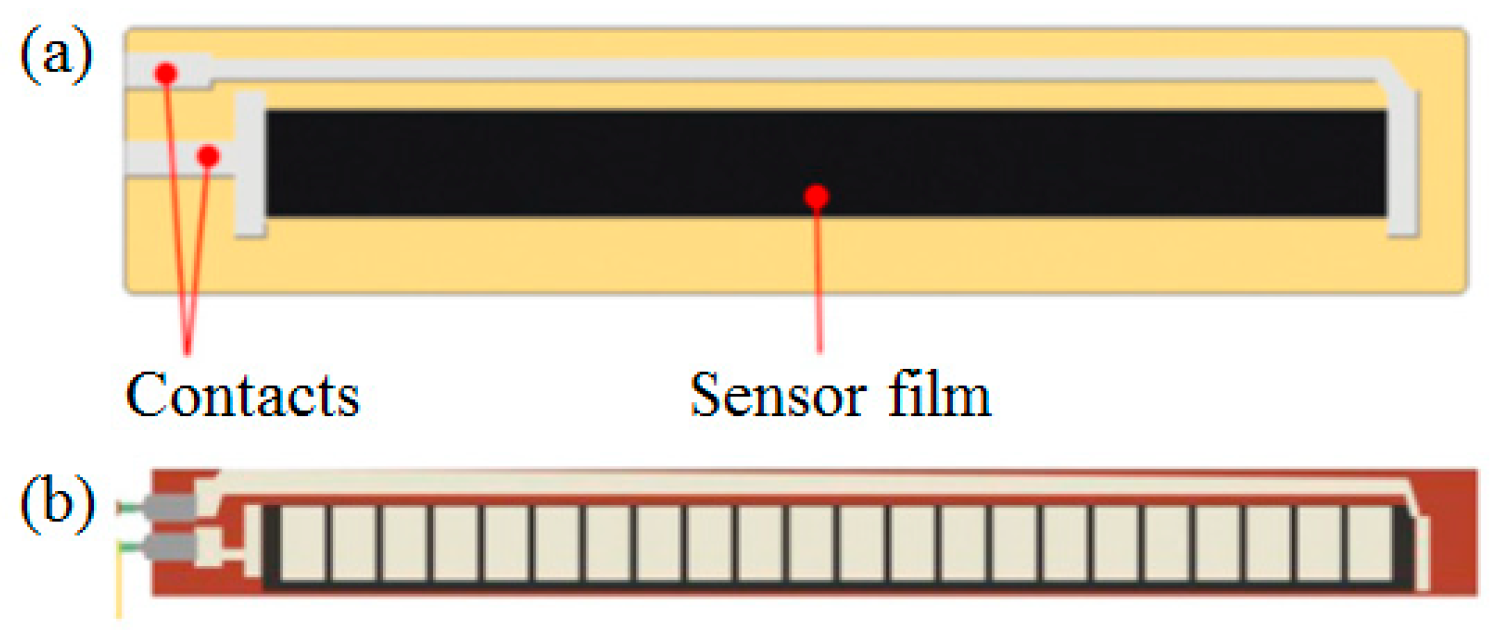
The prototype, based on a flex sensor and a PVDF sensor, was used to monitor a 245/40/R18 tire. The flex sensor (see
Figure 1a,b), due to a series of carbon resistive elements, works like a variable resistance from a constant value for a flat sensor to a maximum value in a totally bended condition (90°). Once attached to the inner part of the tire, the sensor can be used to estimate the curvature variation of the tire due to the bending action, which can be then linked to the working conditions (e.g., rolling speed, vertical load, and length of the contact patch).
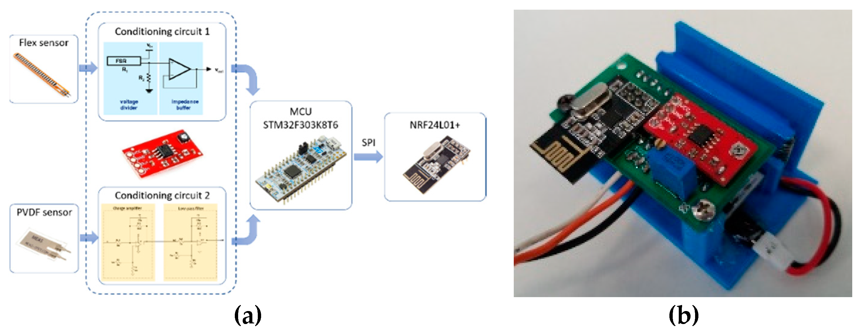
Meanwhile the PVDF sensor (
Figure 2a) is based on a piezo-electric material, therefore it can generate an electric charge proportional to the applied mechanical deformations.
A schematic picture of the proposed electronic system is depicted in
Figure 2a. The data acquisition system (DAS) implemented is mainly composed of two conditioning circuits, a microcontroller and a wireless communication module.
The microcontroller unit (MCU) has two fast 12-bit ADCs with 5 Msps maximum sampling rate, while in our application the sampling frequency is fS = 12 kHz. In addition, the developed DAS can be configured to retrieve data from the sensor both in real-time and off-line. In the first case, the microcontroller sends data packets over a Bluetooth channel to a personal computer; in the second case, the microcontroller collects the signal data so that all the information and numerical data can be stored in a non-volatile SD card through serial interface.
The MCU firmware is written with the Arm Mbed IoT Device Platform and it is based on the Mbed OS 5.8 release, whereas the synchronization between the sampling operation and the writing operation is ensured by interrupt/tread mechanisms. Finally, the wireless communication has been provided adopting the nRF24L01 module.
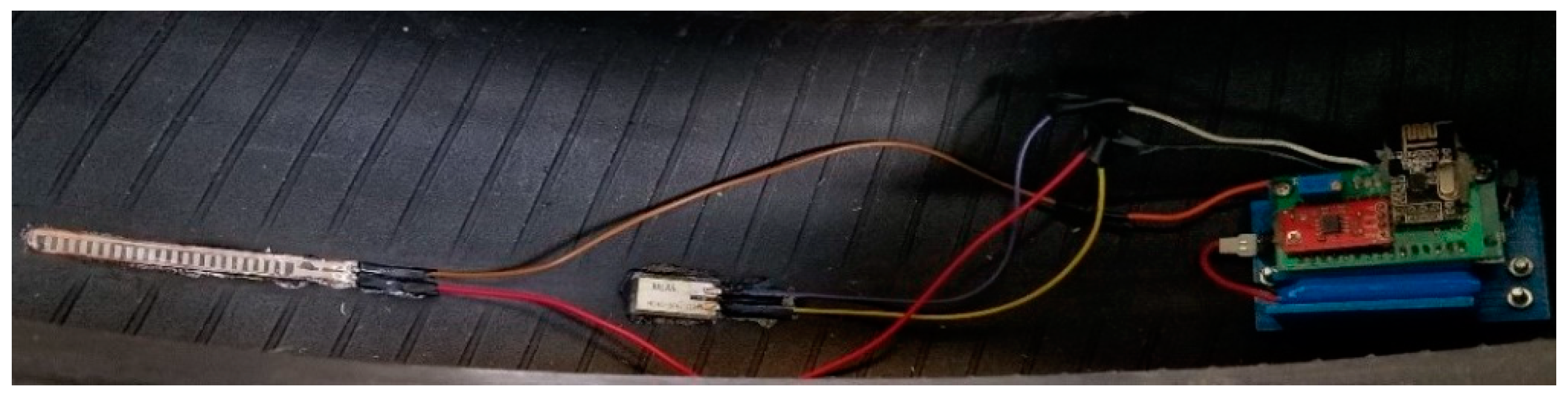
In
Figure 3, it is possible to see how the sensors and the sensing circuit, held by a 3D printed base, have been mounted on the inner part of the tire. An elastic support fixes the sensing circuit base to the tire inner liner.
2.1. Energy Consumption Optimisation
As the sensing circuit will work in autonomy inside the tire, a lot of effort has been put into reducing its energy consumption and trying to create a system as long lasting as possible.
The most inefficient part of the system is the wireless communication, so starting from the firmware, a “power down” mode has been introduced to interrupt the communications whenever the sensor gives no signal. Once the signal is different from the reference value, the microcontroller starts the ISR (interrupt service routine), waking-up the system and allowing communication. Thanks to these modifications, a consumption analysis revealed a decrease in electricity consumption of about 33.4% (from 564 to 169 mAh), while the stand-by consumption has been lowered to 0.46 µAh.
As one would expect, the battery has an important role in the energetic autonomy of the system, at the moment the sensing circuit is powered by a 3.7 V and 500 mAh LiPo battery. In the near future, it will be replaced by a “button cell”, which will also allow for a considerable miniaturization of the system.
2.2. Characteristics of the Flex and PVDF Sensor Signals
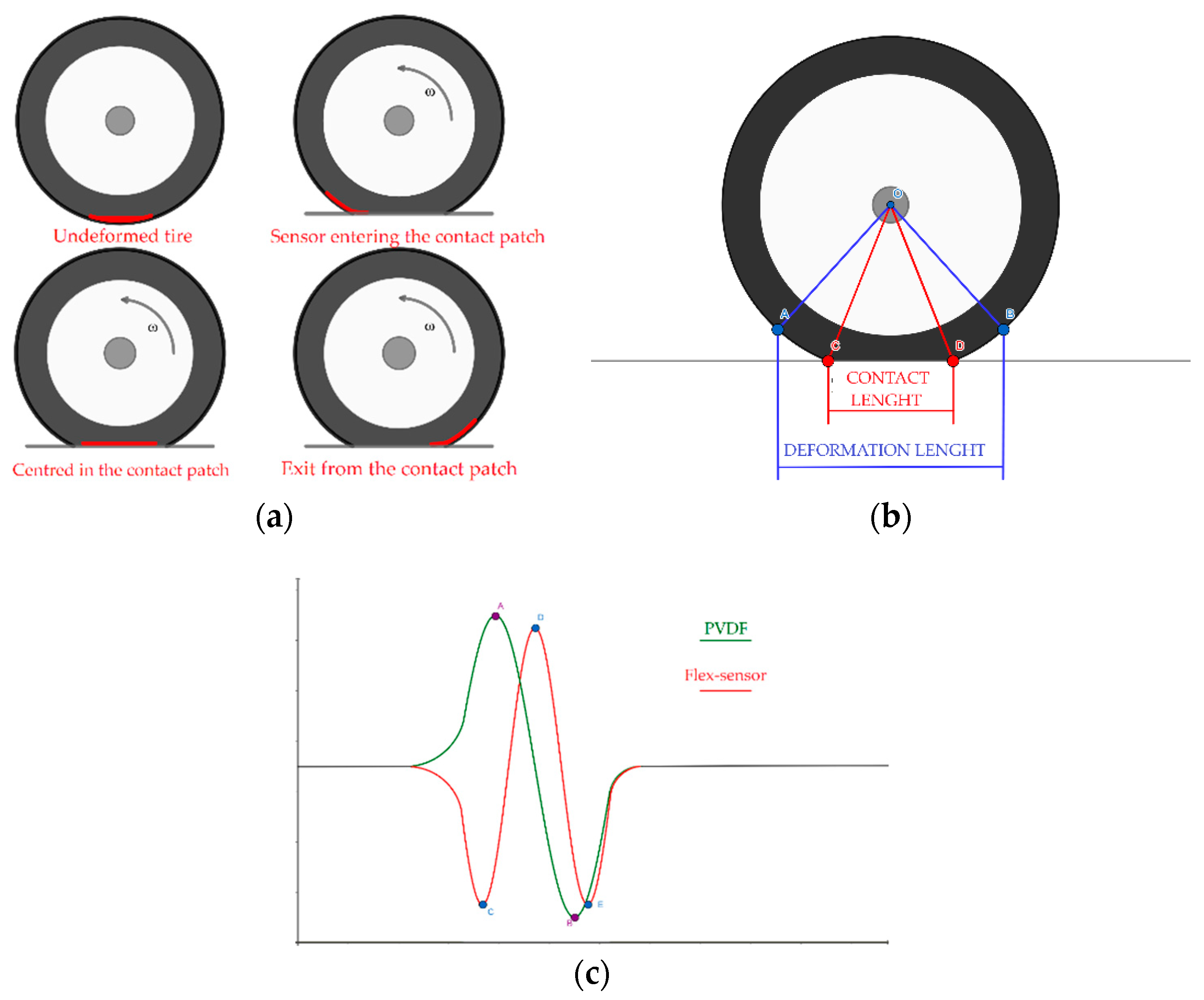
To properly understand how the flex sensor is affected by the tire motion, we should follow its passage through the contact patch. Firstly, the sensor enters the contact patch and starts to be deformed simultaneously with the tire tread band (See
Figure 4a) until the moment in which it is placed exactly in the contact patch. When that happens its curvature decreases, reaching a minimum. Finally, during the exit from the contact patch the sensor curvature increases again, due to the tire tread band deformation. The radius of curvature and its time variation behaviour, in a free-rolling condition, is shown in
Figure 4c.
In the absence of braking, traction or steering forces, the radius of curvature is almost symmetric with respect to the contact patch center (the point D in
Figure 4c). The time variation of the radius of curvature related to the flex sensor can be adopted for estimating the length of the contact patch as shown in
Figure 4b. On this last consideration, it is necessary to point out the difference between the contact length and deformation length (
Figure 4b). As the PVDF returns the derivative form of the flex-sensor output, due to this link between the two sensors output, considerations about the flex-sensor could be applied for the PVDF as well (considering that a variation in value for the flex-sensor output matches with a slope variation for the PVDF). As the preliminary results have been obtained at low tire rolling speed, the PVDF outputs have been not analyzed in detail but only as a verification of the physical meaning of the flex sensor signals. Therefore, the mathematical modelling and the main experimental results are referred to the flex sensor.
2.3. Mathematical Modelling of the Flex Sensor Signal
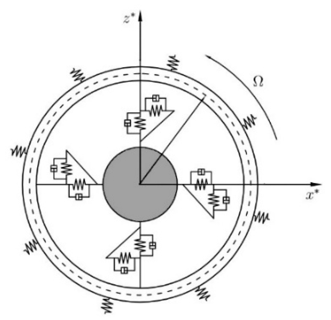
In this section, a mathematical description of the flex sensor measurement is described. The modelling approach is based on the “flexible ring tire model” [
18] (
Figure 5).
As shown in
Figure 5, the treadband structure is modelled as a thin circular elastic ring connected to the wheel hub in circumferential and radial directions through a viscoelastic foundation. Assuming the tire tread band is inextensible, the tire motion equations can be written using the relationships between the radial and tangential ring displacements (−w and v) in Equation (1), the circumferential strain
and the tire inner liner (Equation (2)):
where θ is the angular coordinate of a point belonging to the treadband in the fixed-body reference frame, h is the ring thickness, R is the undeformed ring mean radius and k(θ) is the local curvature. Thanks to the algorithm illustrated in [
19], it is possible to evaluate the tangential and radial displacements in closed form and consequently the local tire curvature.
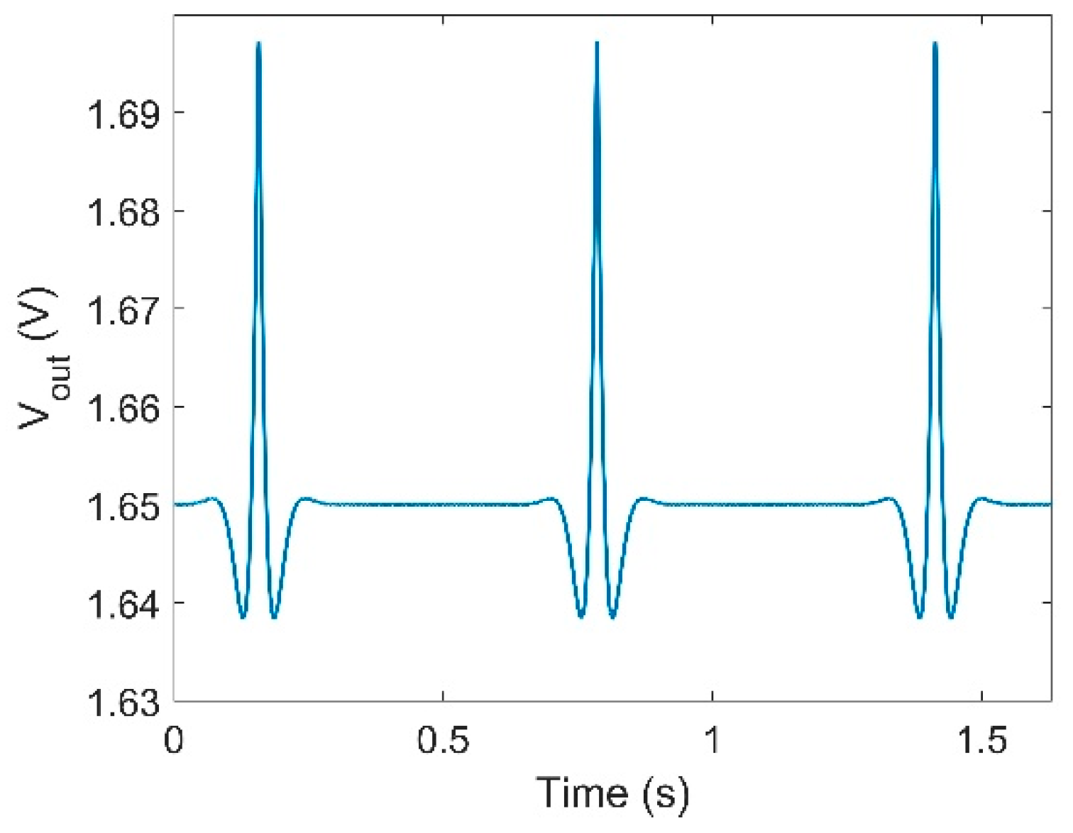
The flex-sensor circuit model is based on the sensor itself, a variable resistance which follows Equation (3) and the voltage divider characterized by Equation (4) (see
Figure 2 for reference).
An example of behavior of the voltage from the flex sensor is presented in
Figure 6.
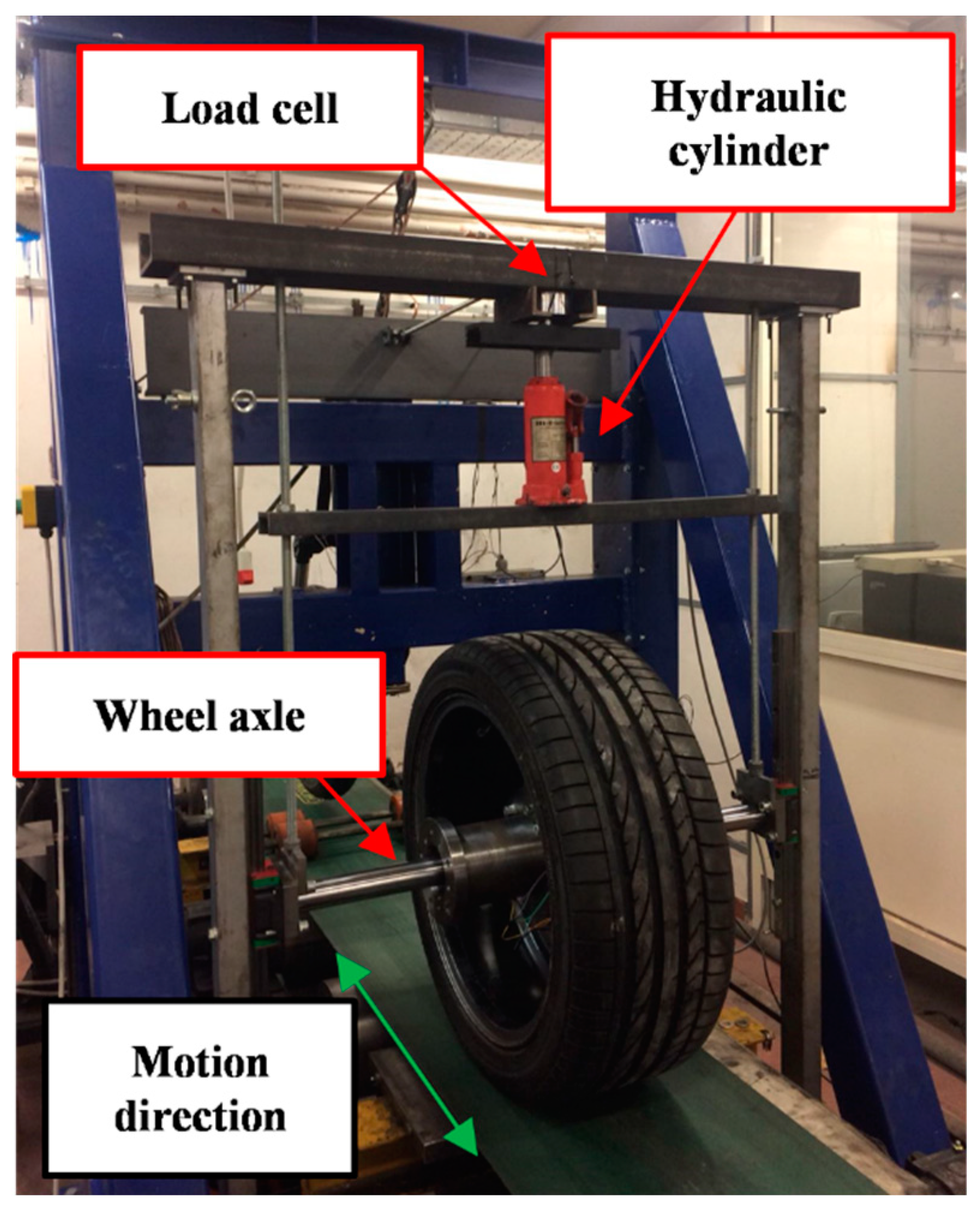
2.4. Tire Test Rig
The test rig used during the tire testing session (shown in
Figure 7) is composed of a portal frame that works as support of the wheel axle.
The wheel axle is mounted on two vertical linear guides in order to transmit the vertical load to the pneumatic tire. On the top of the portal frame, there is a housing for the loading cell, which allows measurement of the vertical applied load. A hydraulic cylinder is then placed between the load cell and a horizontal beam, which is directly connected to the guides. The measurements provided by the flex sensor were obtained for different values of vertical loads and tire rolling speeds. This configuration allowed us to check if the output signals from the sensors were in accordance with their theoretical descriptions.
3. Experimental Results
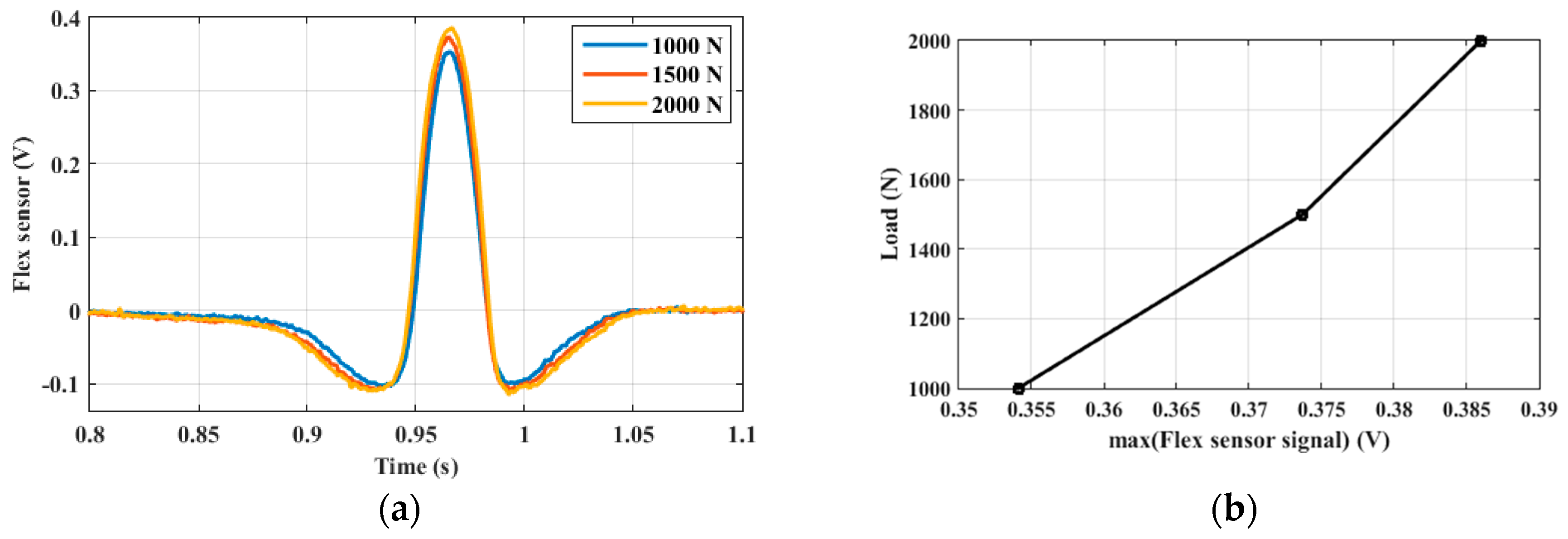
The first testing session focused on the flex sensor signal behavior at low speed (up to 20 Kph); the same test was repeated three times (in
Figure 8a), with each one in different load conditions to show how the sensor signal is affected. The peak value increases with the applied load in the order of 70 mV/50 kg, this result allows the system to estimate the applied load.
Figure 8b shows the variation of the maximum amplitude value with respect to the vertical load (
Figure 8a).
The signals (in
Figure 8a) have a qualitative behavior similar to the theoretical radius of curvature signal presented in
Figure 4c, this is an important feedback about the system trustworthiness.
The
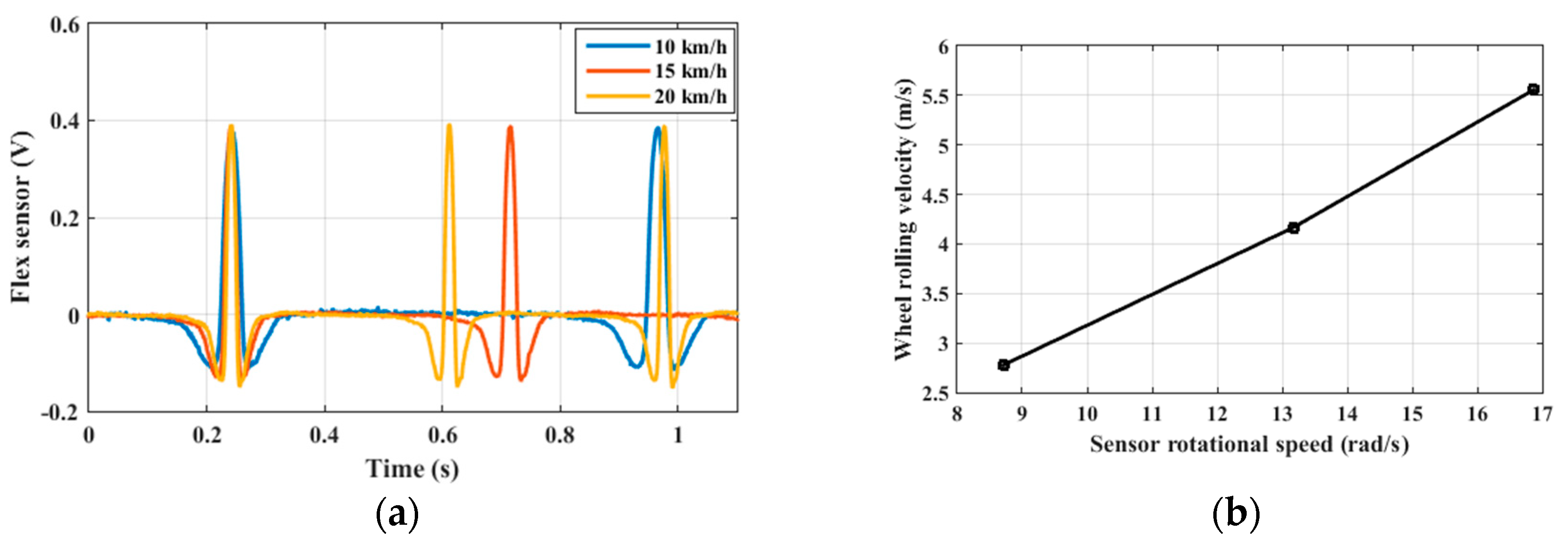
Figure 9a shows a different testing session, based on the same principle. It is obtained by maintaining a constant tire vertical load (2000 N) and varying the wheel rolling velocity in order to identify and check only the speed effects.
Figure 9b relates the wheel rolling velocity for different values of the sensor rotational speed, obtained from the time period between two consecutive positive peaks of the sensor output.
The experimental results presented in
Figure 9a,b demonstrate the possibility to obtain an estimation of the wheel rolling velocity from a signal processing method applied to the wireless measurements. Furthermore, under the hypothesis of a perfect bonding between flex sensor and tire inner liner, the sensor rotational speed coincides with the tire carcass speed. The results of
Figure 9b show a linear relationship between the sensor rotational speed and the wheel rolling velocity.
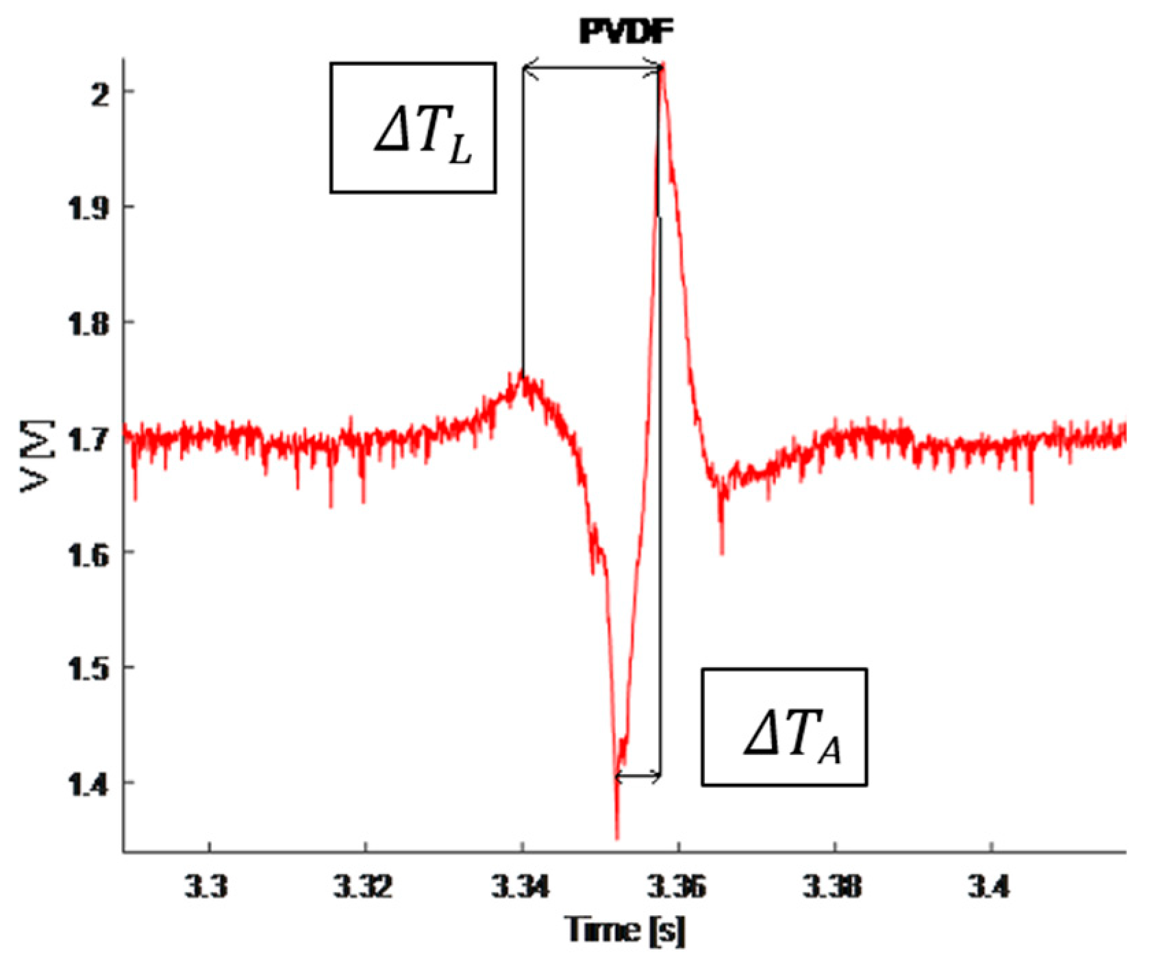
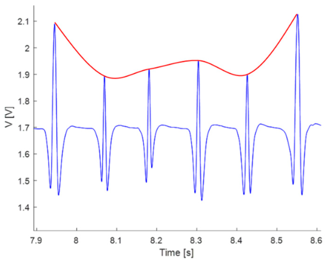
The PVDF also provides a signal (shown in
Figure 10) qualitatively similar to the expected output (
Figure 4c).
Once these tests were completed the research focused on the effects of steering on the signals, mainly from the flex-sensor, in a series of road tests. For instance,
Figure 11 shows a series of events where the intelligent tire “feels” a vertical load variation due to a steering correction.
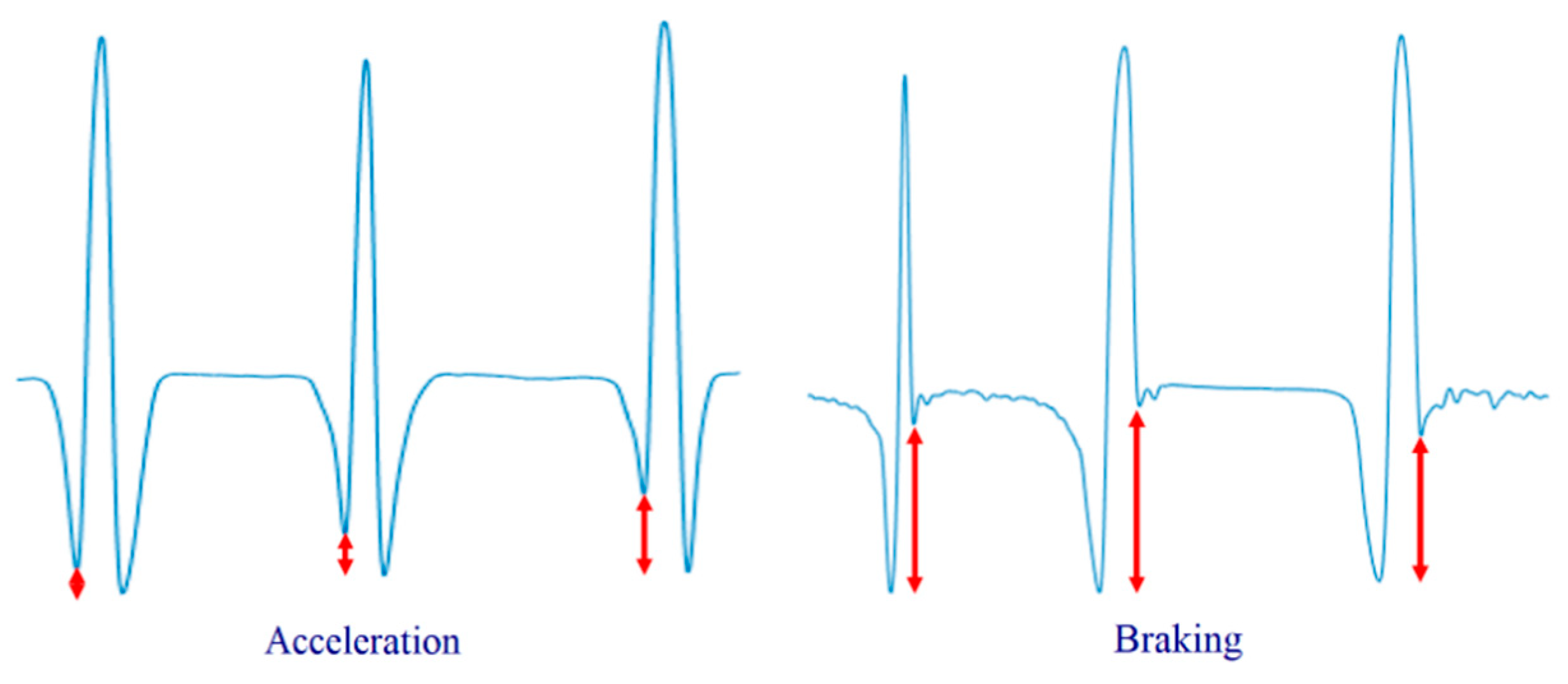
Another important achievement was reached in the road test session: the possibility to estimate the vehicle acceleration and braking actions. Both of them affect the two lower peaks of the flex sensor signal according to the action strength (
Figure 12).
4. Discussion
The test sessions successfully returned the expected theoretical results obtained by studying the “flexible ring tire model”. Starting from the laboratory, the tests focused on the relationship between the output from the sensors and features of interest. Most of the job focused on the flex-sensor, and as a consequence, it has been possible to anticipate what could be discovered in road tests, whereas the PVDF-sensor played the role of controlling the truthfulness of the flex-sensor readings. So, on one hand the prototype has been tested and controlled on its use, on the other hand it has gradually been miniaturized in order to not interfere significantly with the tire motion. The system energy requirement was lowered, by working on the firmware, by 33.4%. Furthermore, improvements were obtained by finding the best compromise between economy, energy consumption and performance of the wireless communication system.
5. Conclusions
In this paper, a cost-effective wireless system for an intelligent tire prototype is presented. The proposed apparatus mainly consists in a sensing circuit equipped with a micro-controller unit, low-power wireless communication module, a low-cost flex sensor and a PVDF sensor to detect the strain rate. A tire model was analysed to predict the flex sensor output.
Subsequently, an experimental activity was conducted in order to analyze the feasibility of the proposed approach. In particular, the test rig was adopted to evaluate the possibility of estimating some tire working condition features from the flex sensor and the PVDF in free-rolling conditions and low speeds.
The research continued with a series of road tests, in which the intelligent tire prototype was tested in cornering, acceleration and breaking in real conditions. Strategies to reduce the sensing circuit energy consumption were investigated. Correlations between measurements and physical parameters were investigated as preliminary analysis. Further improvements of this estimation procedure will include an extensive experimental activity oriented to validate the proposed method with more experimental data.
Author Contributions
Conceptualization, S.S., M.T.; methodology, G.B., A.I., M.Ri.; software, M.Ri.; data curation, M.Ri., L.P., S.S.; writing—original draft preparation, L.P.; writing—review and editing, G.B., A.I., M.Ri., S.S., M.T.; supervision, M.Ru.
Funding
This research received no external funding.
Acknowledgments
The authors would like to thank Giuseppe Iovino and Gennaro Stingo for their technical support.
Conflicts of Interest
The authors declare no conflict of interest.
References
- Lee, H.; Taheri, S. Intelligent tires-a review of tire characterization literature. IEEE Intell. Transp. Syst. Mag. 2017, 9, 114–135. [Google Scholar] [CrossRef]
- Acosta, M.; Kanarachos, S.; Blundell, M. Virtual tyre force sensors: An overview of tyre model-based and tyre model-less state estimation techniques. Proc. Inst. Mech. Eng. Part D J. Automob. Eng. 2018, 232, 1883–1930. [Google Scholar] [CrossRef]
- Acosta, M.; Kanarachos, S.; Blundell, M. Road friction virtual sensing: A review of estimation techniques with emphasis on low excitation approaches. Appl. Sci. 2017, 7, 1230. [Google Scholar] [CrossRef]
- Niola, V.; Quaremba, G.; Savino, S. The objects location from images binarized by means of self-learning neural network. WSEAS Trans. Syst. 2005, 4, 417–423. [Google Scholar]
- Tuononen, A. Optical position detection to measure tyre carcass deflections. Veh. Syst. Dyn. 2008, 46, 471–481. [Google Scholar] [CrossRef]
- Cullen, J.; Arvanitis, N.; Lucas, J.; Al-Shamma’a, A. In-field trials of a tyre pressure monitoring system based on segmented capacitance rings. Measurement 2002, 32, 181–192. [Google Scholar] [CrossRef]
- Magori, V.; Magori, V.R.; Seitz, N. On-Line Determination of Tyre Deformation, a Novel Sensor Principle. In Proceedings of the IEEE Ultrasonics Symposium, Sendai, Japan, 5–8 October 1998. [Google Scholar]
- Moona, K.S.; Liangb, H.; Yi, J.; Mika, B. Tire tread deformation sensor and energy harvester development for “Smart Tire“ applications. In Proceedings of the Sensors and Smart Structures Technologies for Civil, Mechanical, and Aerospace System, San Diego, CA, USA, 19–22 March 2007. [Google Scholar]
- Yi, J. A piezo-sensor-based ‘smart tire’ system for mobile robots and vehicles. IEEE/ASME Trans. Mechatron. 2008, 13, 95–103. [Google Scholar] [CrossRef]
- Todoroki, A.; Miyatani, S.; Shimamura, Y. Wireless strain monitoring using electrical capacitance change of tire: Part I—With oscillating circuit. Smart Mater. Struct. 2003, 12, 403–409. [Google Scholar] [CrossRef]
- Todoroki, A.; Miyatani, S.; Shimamura, Y. Wireless strain monitoring using electrical capacitance change of tire: Part II—Passive. Smart Mater. Struct. 2003, 12, 410–416. [Google Scholar] [CrossRef]
- Matsuzaki, R.; Todoroki, A. Passive wireless strain monitoring of actual tire using capacitance–resistance change and multiple spectral features. Sens. Actuators A 2006, 126, 277–286. [Google Scholar] [CrossRef]
- Matsuzaki, R.; Todoroki, A. Wireless flexible capacitive sensor based on ultra-flexible epoxy resin for strain measurement of automobile tires. Sens. Actuators A 2007, 140, 32–42. [Google Scholar] [CrossRef]
- Yilmazoglu, O.; Brandt, M.; Sigmund, J.; Genc, E.; Hartnagel, H.L. Integrated InAs/GaSb 3D magnetic field sensors for ‘the intelligent tire. Sens. Actuators A 2001, 94, 59–63. [Google Scholar] [CrossRef]
- Garcia-Pozuelo, D.; Olatunbosun, O.; Yunta, J.; Yang, X.; Diaz, V. A novel strain-based method to estimate tire conditions using fuzzy logic for intelligent tires. Sensors 2017, 17, 350. [Google Scholar] [CrossRef] [PubMed]
- Garcia-Pozuelo, D.; Yunta, J.; Olatunbosun, O.; Yang, X.; Diaz, V. A strain-based method to estimate slip angle and tire working conditions for intelligent tires using fuzzy logic. Sensors 2017, 17, 874. [Google Scholar] [CrossRef] [PubMed]
- Yang, X.; Olatunbosun, O.; Garcia-Pozuelo Ramos, D.; Bolarinwa, E. FE-Based Tire Loading Estimation for Developing Strain-Based Intelligent Tire System; SAE: Detroit, MI, USA, 2015. [Google Scholar]
- Gong, S. A Study of In-Plane Dynamics of Tires; Delft University: Delft, The Netherlands, 1993. [Google Scholar]
- Garcia-Pozuelo, D.; Olatunbosun, O.; Strano, S.; Terzo, M. A real-time physical model for strain-based intelligent tires. Sens. Actuators A Phys. 2019, 288, 1–9. [Google Scholar] [CrossRef] [Green Version]
© 2019 by the authors. Licensee MDPI, Basel, Switzerland. This article is an open access article distributed under the terms and conditions of the Creative Commons Attribution (CC BY) license (http://creativecommons.org/licenses/by/4.0/).

 ,
, 


