1. Introduction
Magneto-rheological elastomers (MREs) are capable of changing their stiffness and damping in response to an applied magnetic field [
1,
2]. This characteristic allows for the development of controllable devices for vibration isolation [
3,
4], overcoming the limits of traditional passive isolators. In fact, passive isolators shift the system’s natural frequency far enough away from the range of the forcing frequencies to avoid resonance phenomena [
5]. These types of isolators perform their tasks efficiently in machines operating in steady-state conditions. However, if the forcing frequencies are not known a priori or if the resonance condition is frequently crossed, the ability to change the isolators’ characteristics in real time can lead to a significant improvement isolation.
MRE compounds are composed of an elastomeric matrix containing magnetizable particles of nano to micro sizes. During the curing phase, the compound is subjected to the action of a magnetic field to rearrange and to orient the ferromagnetic particles along the strength lines of the magnetic field. The materials’ characteristics, in particular the stiffness, vary with the intensity of the magnetic field, depending on the particles’ dimensions [
6,
7] and their rearrangement in the matrix.
The adoption of MRE isolators [
8,
9] may be particularly useful for solving machinery vibration isolation problems, as MRE isolators combine the reliability of passive devices with the ability of active devices by adapting their characteristics to the actual machine and environment conditions.
In this paper, an analytical model is presented that describes the influence of the volume fraction of magnetic particles on the magneto-rheological effect, defined as the material shear modulus increment caused by a magnetic field, on MREs.
MRE samples were, therefore, prepared using silicone and polyurethane rubbers. To create an evident magneto-rheological effect, it is necessary to use an elastomeric matrix that is not particularly stiff; for this reason, our experiments were carried out on silicone samples.
These samples were prepared by adopting a nylon mold that allowed us to place permanent magnets at its extremities so that, during the polymerization phase, the iron-carbonyl particles mixed with the liquid silicone, aligning along the strength lines of the magnetic field and forming anisotropic chain-like structures that became locked in place upon the final cure.
To adopt MREs as vibration isolators, for light structures excited along the horizontal direction, the formed samples were tested with static compression loads and subjected to variable shear excitations. To carry out these dynamic tests, an experimental set-up was developed, in which an electrodynamic shaker was adopted to induce a shear load with assigned amplitude and frequency on two samples at a time. The samples were placed on the core of a coil so that it was possible to generate a magnetic field crossing the sample material. Thus, in this way, it was possible to investigate the effect of the load frequency at different levels of magnetic field intensity.
2. The Magneto-Rheological Effect
MREs are compounds containing magnetizable particles (with varying sizes of 3–10 μm) in a non-magnetic matrix. Their mechanical and rheological properties can be reversibly changed upon exposure to a suitable magnetic field [
10]. The physical material property, which undergoes a significant variation depending on the strength of the magnetic field, is the shear elastic modulus; this characteristic allows for the realization of MRE pads with controllable stiffness. The magneto-rheological effect reflects the shear modulus change with respect to the value that it assumes in the absence of a magnetic field. MRE compounds may be isotropic if the particles are randomly dispersed or anisotropic if the particles are arranged in columns. Experimental tests have shown that the magneto-rheological effect is significantly larger in anisotropic MREs [
11]. This arrangement can be obtained by immersing the liquid mixture in a static magnetic field during the vulcanization phase.
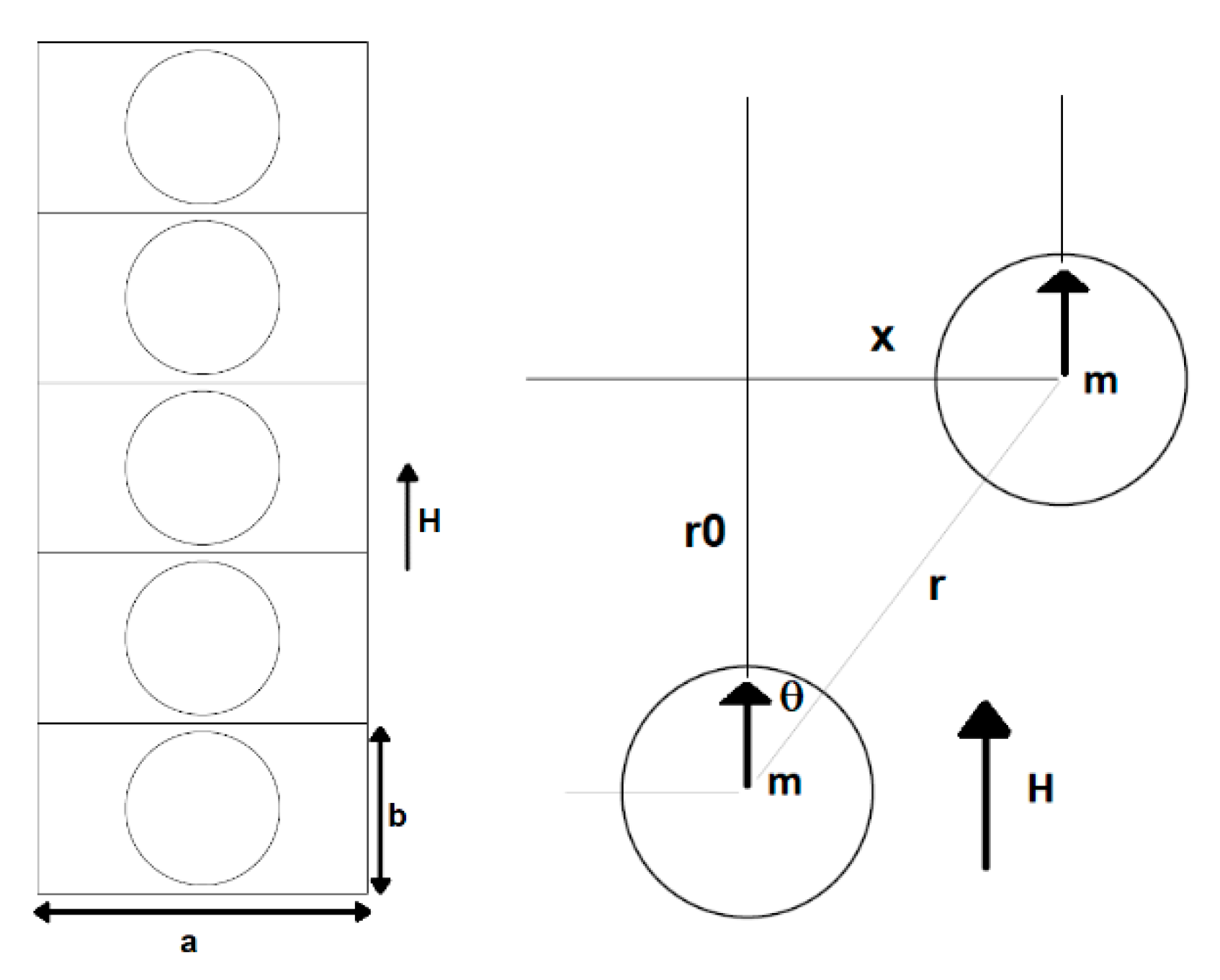
Figure 1 shows a schematic of a column of equally sized spherical particles, arranged at the same distance from each other, subjected to magnetic field H.
To estimate the magneto-rheological (MR) effect, a static model was developed. First, it must be noted that the compound shear modulus G, in the absence of a magnetic field, depends on the matrix module,
G0, and on the amount of iron powder. The following formula can be used to evaluate G as a function of the iron particles’ volume fraction ϕ [
12]:
To estimate the change in shear stress G
m due to the magnetic field, Jolly et al. proposed a dipole model [
13]. This model is based on the hypothesis that all the particles are perfectly spherical and arranged in equidistant columns. Applying an external magnetic field parallel to the column, the inter-particle magnetic force induces added shear stress. The interaction energy of the two dipoles was calculated by Rosensweig [
14] as follows:
where
m1 and
m2 are the magnetic dipoles strength, μ
0 is the vacuum permeability, and μ
1 is the relative permeability of the medium. The stress induced by the magnetic field can be calculated from the derivative of average energy density
U =
n E12/
V, where
n is the particles’ number and
V is the volume occupied by the particles:
where
ε = x/r0 is the shear strain of the particle column and
d is the particle diameter. The magneto-induced shear storage modulus is as follows:
where
JP is the dipole moment magnitude per unit particle volume. The parameter
h =
r0/
d gives an indication of the distance between the particles. Based on the schematic of
Figure 1,
b =
d·
h, and the gap between the particles is equal to
d·(
h − 1). The particles are equally spaced if
a =
b and the iron particles’ volume fraction ϕ is
Then, remembering the law of Frohlich–Kennelly [
15],
where
MS is the saturated magnetization,
H is the magnetic field strength, and μ
p is the relative permeability of the particles.
The following is therefore true:
Using Equations (1) and (8), it is possible to evaluate the MR effect, which is defined as follows:
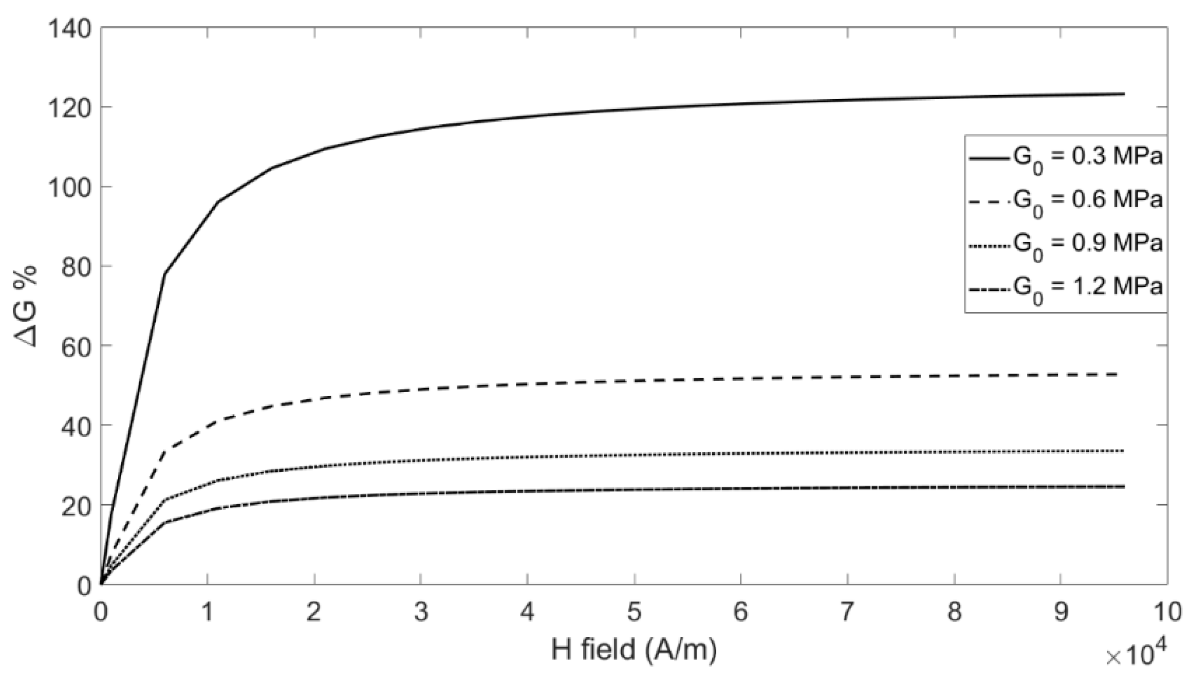
Figure 2 shows the MR effect as a function of the
H field for ϕ = 0.27 and for some values of the matrix shear modulus, G
0. The curves were obtained for iron saturation magnetization
Ms = 2.1 T, μp = 1000, and μ
1 = 1 (elastomeric matrix). It can be observed that the MR effect is greater for lower values of G
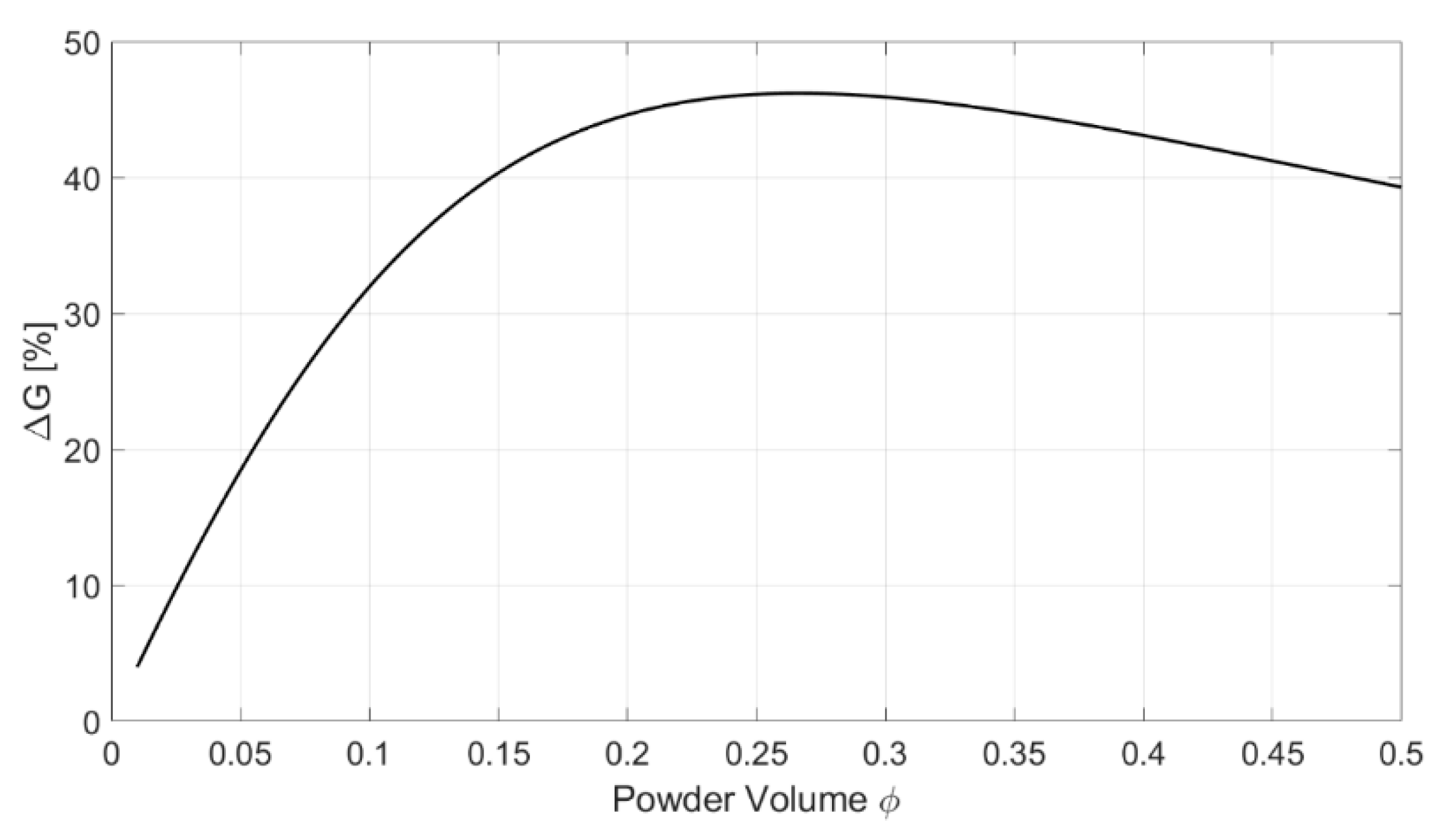
0. The maximum values of ΔG, as a function of the powder volume fraction ϕ, are shown in
Figure 3.
The MR effect reaches the maximum value for ϕ in the range of 0.25–0.30; with a greater quantity of powder, the MR effect decreases.
It is well known that the dynamic behavior of an elastomer differs from its static behavior due to its visco-elastic properties, which are characterized by hysteretic behavior. In order to study both static and dynamic behavior, magneto-rheological rubber samples were prepared for use in our experimental investigations.
3. MRE Sample Preparation
MRE matrixes are usually made of natural rubber or silicone rubber, as they have a low stiffness; therefore, the magnetorheological effect is more evident [
16,
17]. Here, the MRE samples were composed of a silicon elastomer matrix (Prochima GLS-10), characterized by 10 shore-A hardness, with micro iron-carbonyl particles (4–6 μm); the particles’ volume percentage was equal to 25%.
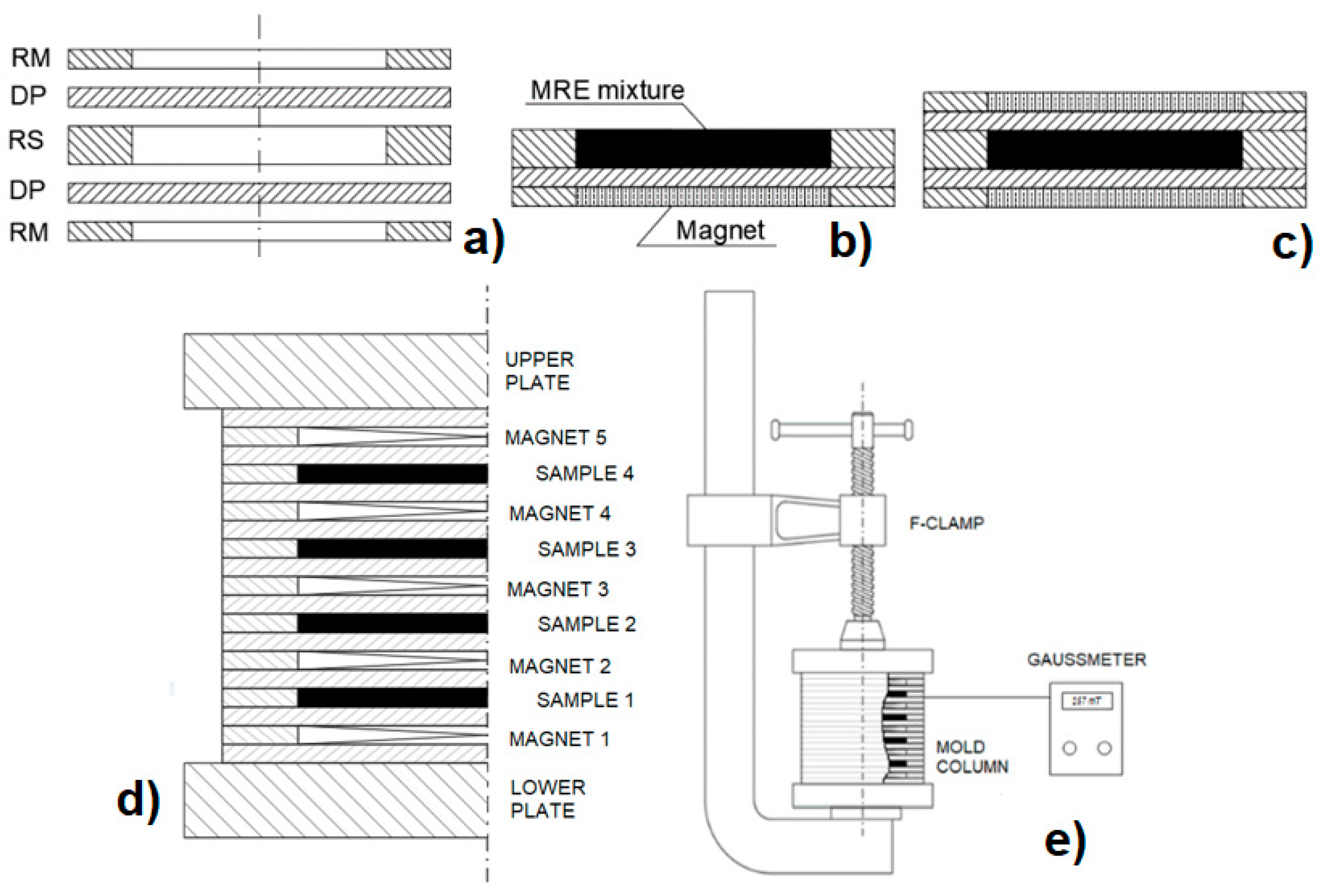
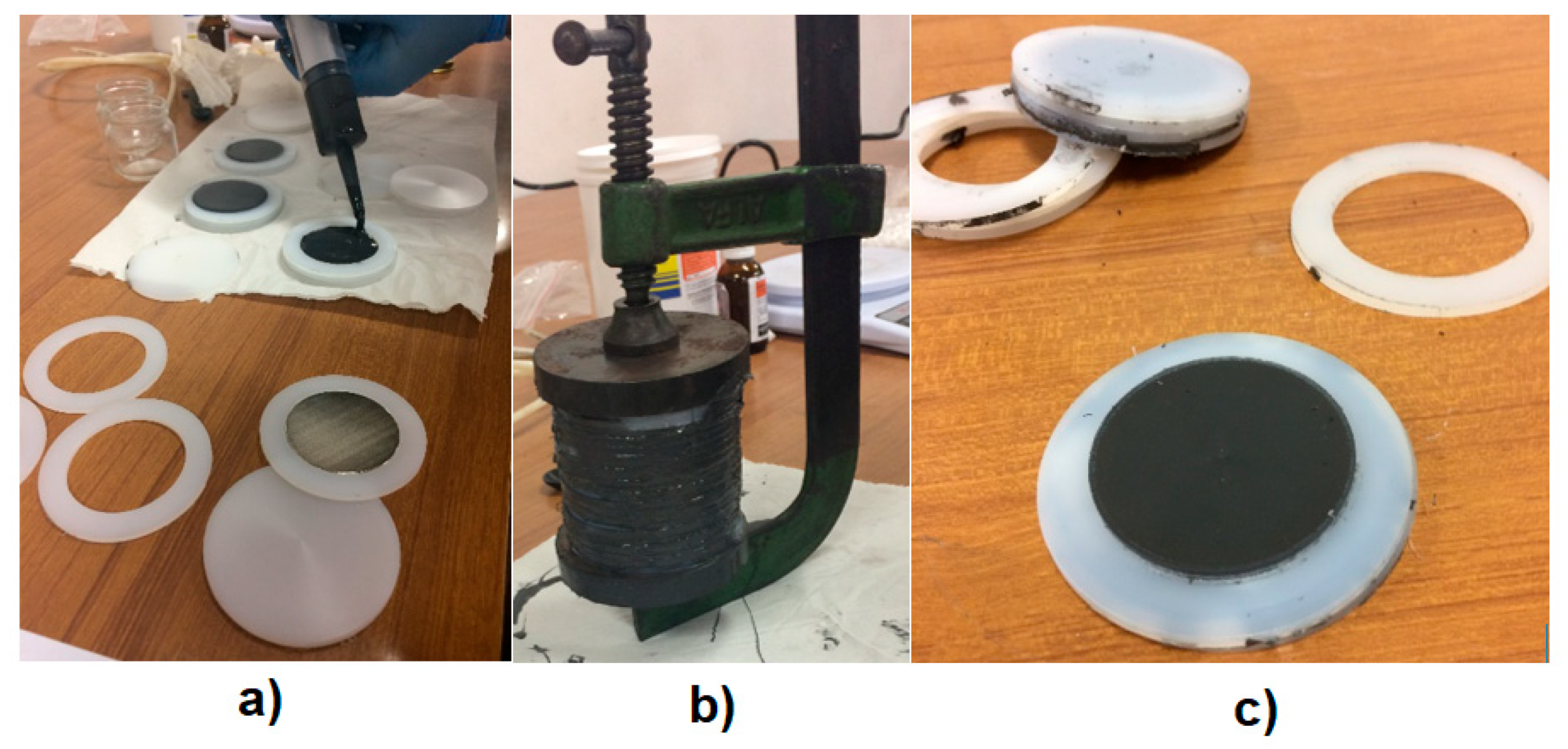
The samples were formed in a nylon mold (
Figure 4) (RS), in which the MRE liquid mixture was cured; two plastic diaphragms (DP) were adopted to separate the mixture from two neodymium permanent magnets, contained in plastic rings (RM) and characterized by a maximum energy product of 263–287 kJ/m
3. The magnetic field generated by the permanent magnets had the effect of orienting and aligning the particles according to the force lines of the magnetic field.
The magnetic field intensity, measured by placing the probe of a gaussmeter (Brockhous BMG101) between the sample and the nylon diaphragm, was equal to 190 mT.
The mold containing the mixture was previously placed in a vacuum chamber, at about 50 mbar, twice for about 30 min to remove air bubbles from the mixture.
The vacuum chamber was composed of a steel pipe, which was closed at the ends with two plates; in the contact zone between the pipe and plates, there was an O-ring to ensure the airtightness [
18]. When the vacuum pump was initiated, the plates were squeezed on the pipe, so no devices were required to connect the plates and pipe.
To prevent bonding between the MRE sample and the internal mold surface and to easily extract the formed sample from the mold, a wax-based release agent was used. The liquid mixture, which was poured into the mold, was cured at constant ambient temperature for about 24 h.
Figure 5 shows several depictions of the sample preparation phases. The sample diameter and height were equal to 50 and 6 mm, respectively. The main sample properties are reported in
Table 1; it was noted that the shore-A hardness did not vary as the magnetic field increased.
4. Coil Characteristics
To characterize the material properties, the sample was tested by means of an experimental set-up containing a coil that produces a magnetic field whose strength lines are parallel to the particle columns of the MRE material. The tests were performed under different intensities of the magnetic field, which were obtained by adjusting the coil supply’s current intensity.
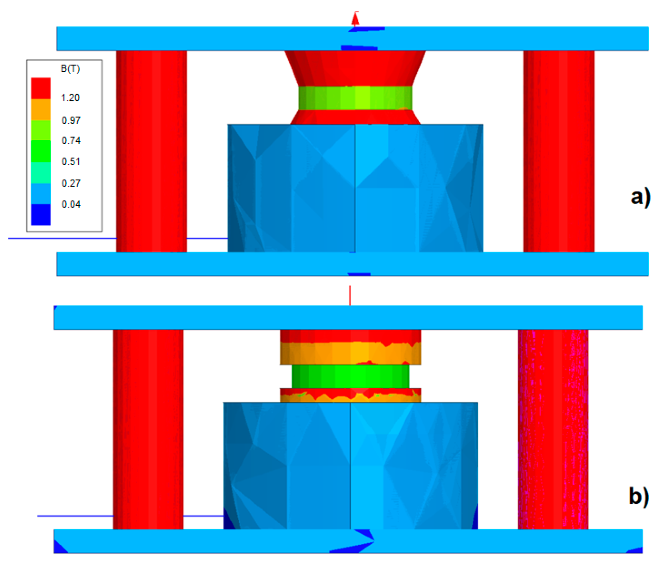
To generate an adequate magnetic field, a coil and magnetic circuit were designed. In the design phase, to evaluate the magnetic flux that crosses the sample, an FEM model, developed in an Ansys Maxwell
® environment, was adopted. The first configuration consisted of a cylindrical MRE element with a diameter and height of 50 and 10 mm, respectively; this element was inserted between two cylindrical steel elements (ϕ 60 × 10 mm). The coil had an inner diameter of 60 mm, an outer diameter of 108 mm, and a height of 100 mm. Inside the coil, there was a 100-mm high cylindrical steel core (
Figure 6a). The saturation value of the magnetic field in the MRE was about 800 mT; to obtain it, 10,000 ampere-turns were required.
In the second configuration, to optimize the magnetic flux, the two cylindrical steel elements were replaced with two conical frustum elements with the following dimensions: bottom diameter: 60 mm; top diameter: 24 mm; height: 10 mm (
Figure 6b). In this case, to reach the saturation value of the magnetic field, only 6000 ampere-turns were required.
The materials adopted for the FEM simulations were as follows: steel Aisi-1008 for the plates and core; copper for the coil; rubber and iron powder for the MRE pad. With respect to the second configuration (
Figure 6b), considering a maximum current of 4 A, the coil required 1500 turns, was made of a 1.02-mm diameter cable (AWG17), and had an overall length equal to 310 m (resistance: 6.9 Ω; maximum dissipated power: 109 W).
5. MRE Characterization Tests
The realized samples were characterized by anisotropic chain-like structures, which were able to exhibit significant magneto-rheological effect if the magnetic field was applied in the direction of the particle chains that were parallel to the cylindrical samples’ axes. Therefore, they were subjected to static forces acting along the samples’ axes and to variable shear forces acting in the perpendicular direction. In both cases, the tests were performed under different intensities of the magnetic field, which were obtained by adjusting the coil supply’s current intensity. The results of the two types of tests are described below:
- (a)
The cylindrical MRE samples were subjected to compression tests by means of a mechanical press to characterize the load–displacement trend and to identify the axial stiffness upon exposure to different values of the magnetic field. Another kind of axial test was then performed, compressing the samples between the two rigid plates of the mechanical press and keeping their distance constant; the axial load was detected for different values of the magnetic field intensity.
- (b)
The samples were tested under a constant compression load and a variable (harmonic) shear load. The tests were performed for different frequencies of the shear load and for different values of the magnetic intensity field.
5.1. Axial Characterization
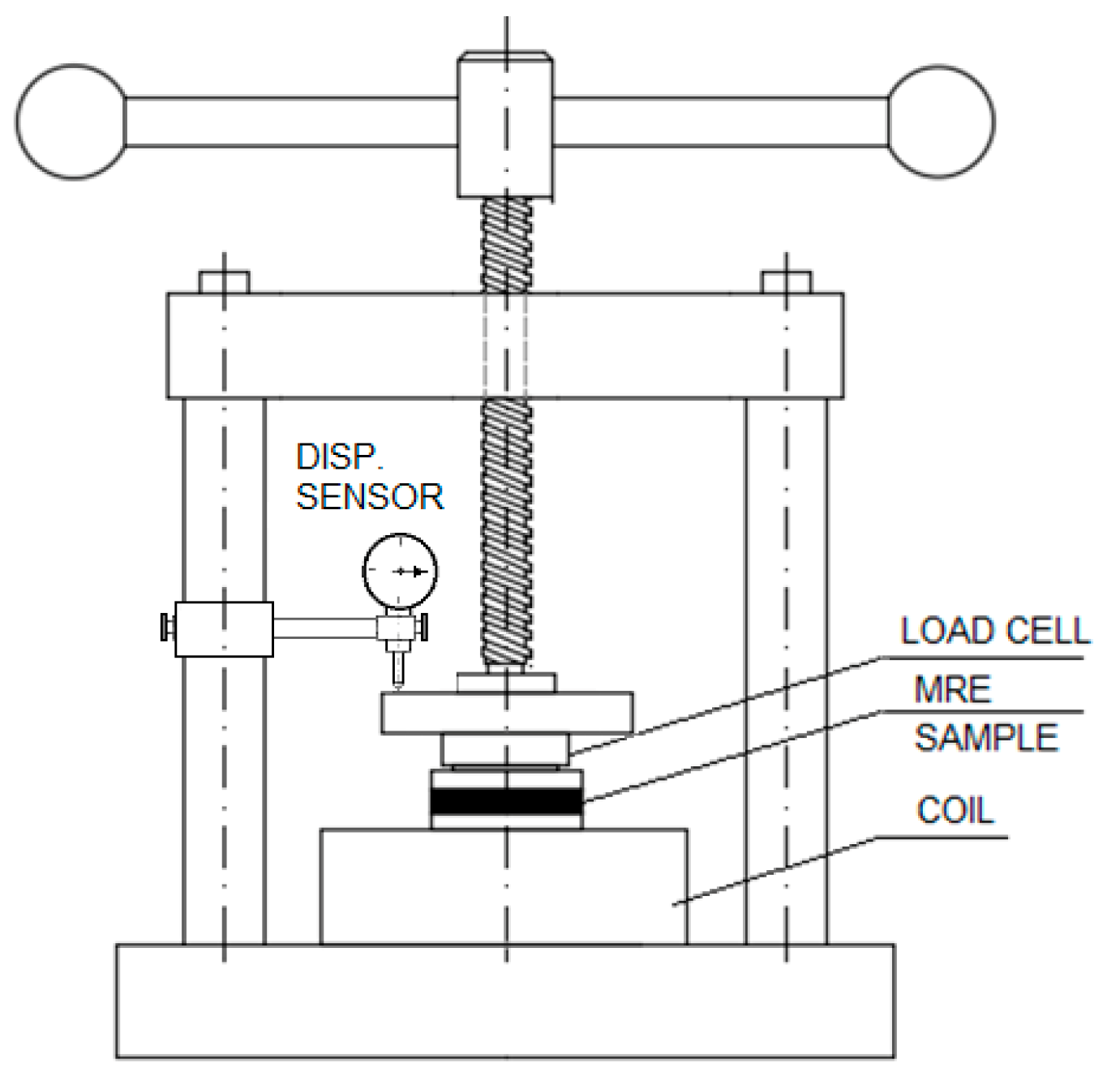
The axial characterization was performed by assigning a continuously increasing and decreasing compression deformation to the MRE sample at the rate of about 0.01 mm/s. The test was repeated for different current intensities circulating in the coil windings. The axial force exerted by the screw press was detected by means of a load cell (
Figure 7), while the corresponding deformation was detected by means of a centesimal comparator.
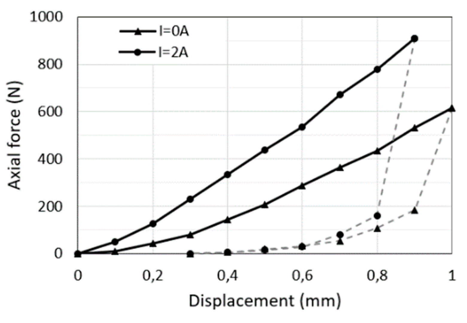
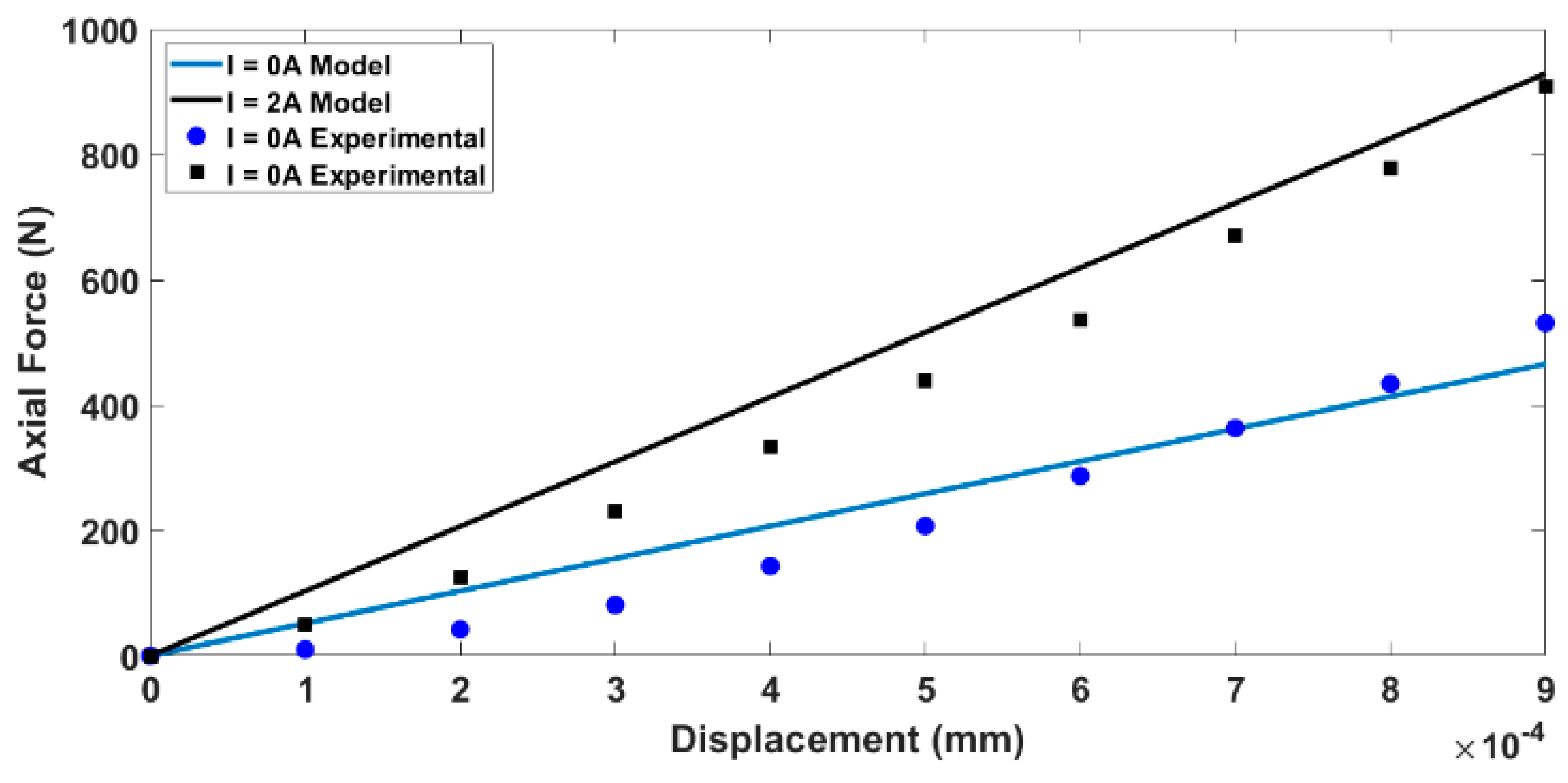
The first test was conducted with the material not activated (i.e., the coil not powered). The force–displacement trend (
Figure 8) was almost linear (slightly hardening). At the beginning of the unloading phase (dashed line), the load exhibited a sharp reduction attributable to the material hysteresis.
Figure 8 shows the test performed by feeding the coil at 2 A. There was an evident axial stiffening (about 65%), and in this case, at the beginning of the unloading phase, the diagram shows that there was a consistent force reduction.
It is possible to compare the experimental results with the theoretical one obtained by means of the model presented in
Section 2. For the prepared samples, the matrix modulus G
0 was equal to 0.3 MPa, and ϕ was equal to 0.25. Based on Equation (1), G = 0.66 MPa. Considering valid the relation for linear-elastic materials, Young’s modulus is as follows: E = 2 G (1 + ν), where ν is the Poisson ratio. Considering the measured Poisson ratio (0.2) and the estimated G modulus (0.66 MPa), the following was determined: E = 1.57 MPa. In the case of rubber-like materials and for compressions limited to 10%, Hooke’s law holds true [
19].
The sample’s theoretical axial stiffness can be evaluated as k = EA/h, where
A is the sample’s cross-section area, and
h is the height.
Figure 9 shows good agreement between the experimental and theoretical results for the two values of current I.
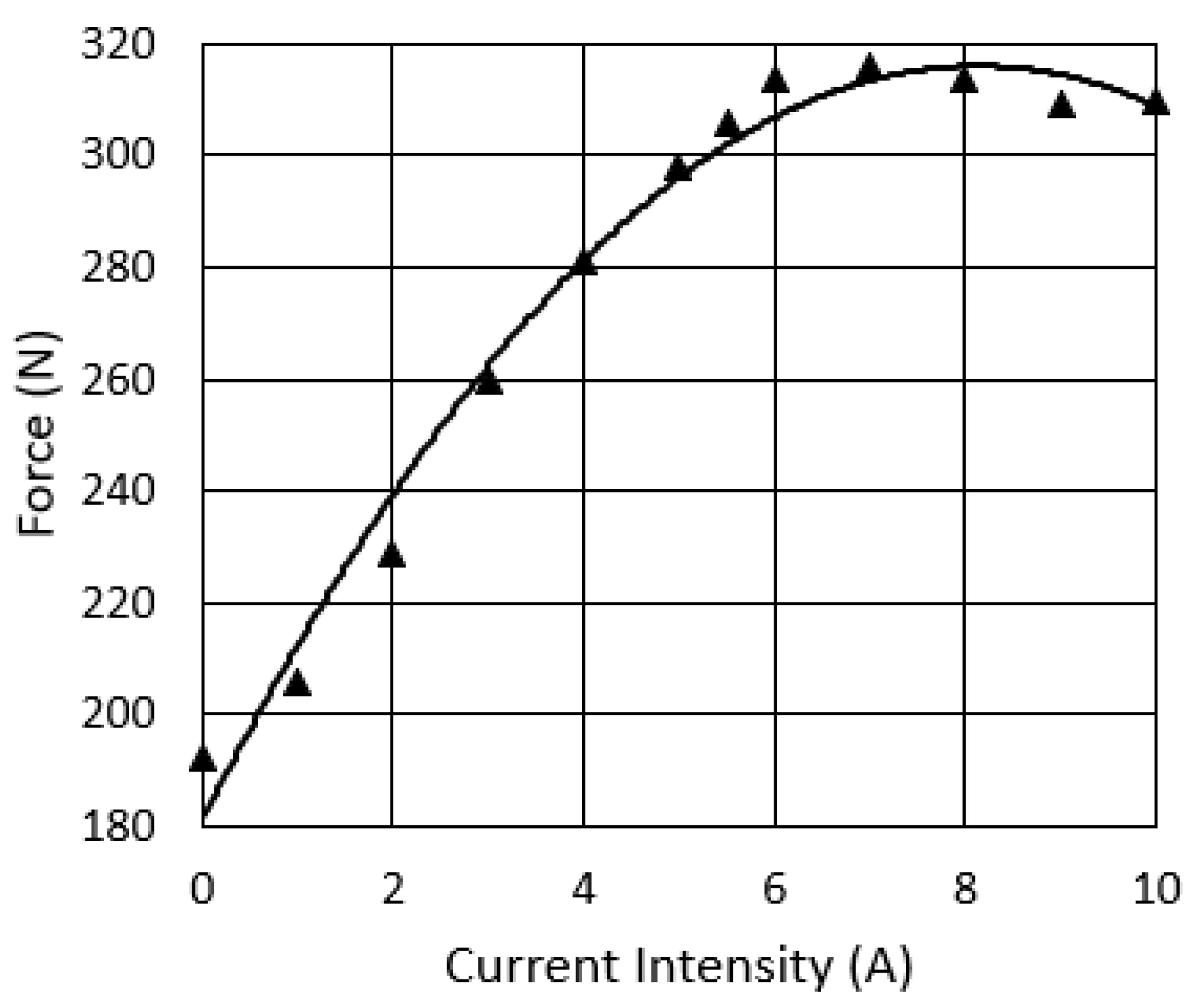
Another kind of static test was performed on the sample; without feeding the coil, the sample was compressed between two plates. Keeping constant the distance between the plates, the axial force was then measured as the values of the coil current intensity increased. The results of this test, as reported in
Figure 10, show that the axial force increased, with an almost linear trend, until the current intensity reached 6 A, with an axial load increment equal to about 63%; under greater current intensity, the axial load did not increase further (saturation).
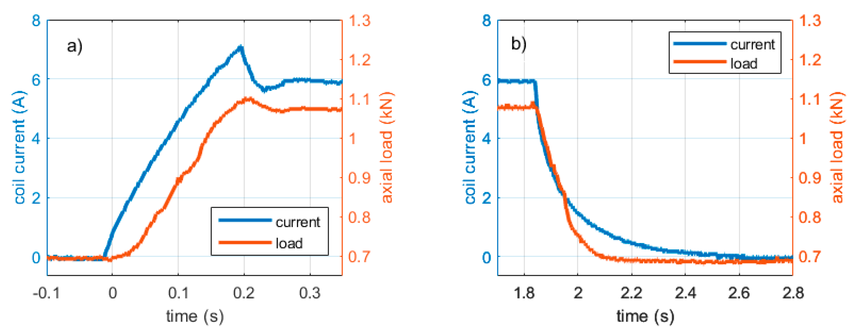
The delay of the load variation, with respect to the current variation, is shown in
Figure 11 for both the load and unload phase; the test was performed by feeding the coil from 0 to 6 A and then returning to 0 A. The test results show that the MRE sample exhibited good reactivity during the increasing of the current intensity (loading), whereas, in the unloading phase, it reacted more slowly. In any case, the delay was compatible with a rapid and reversible control.
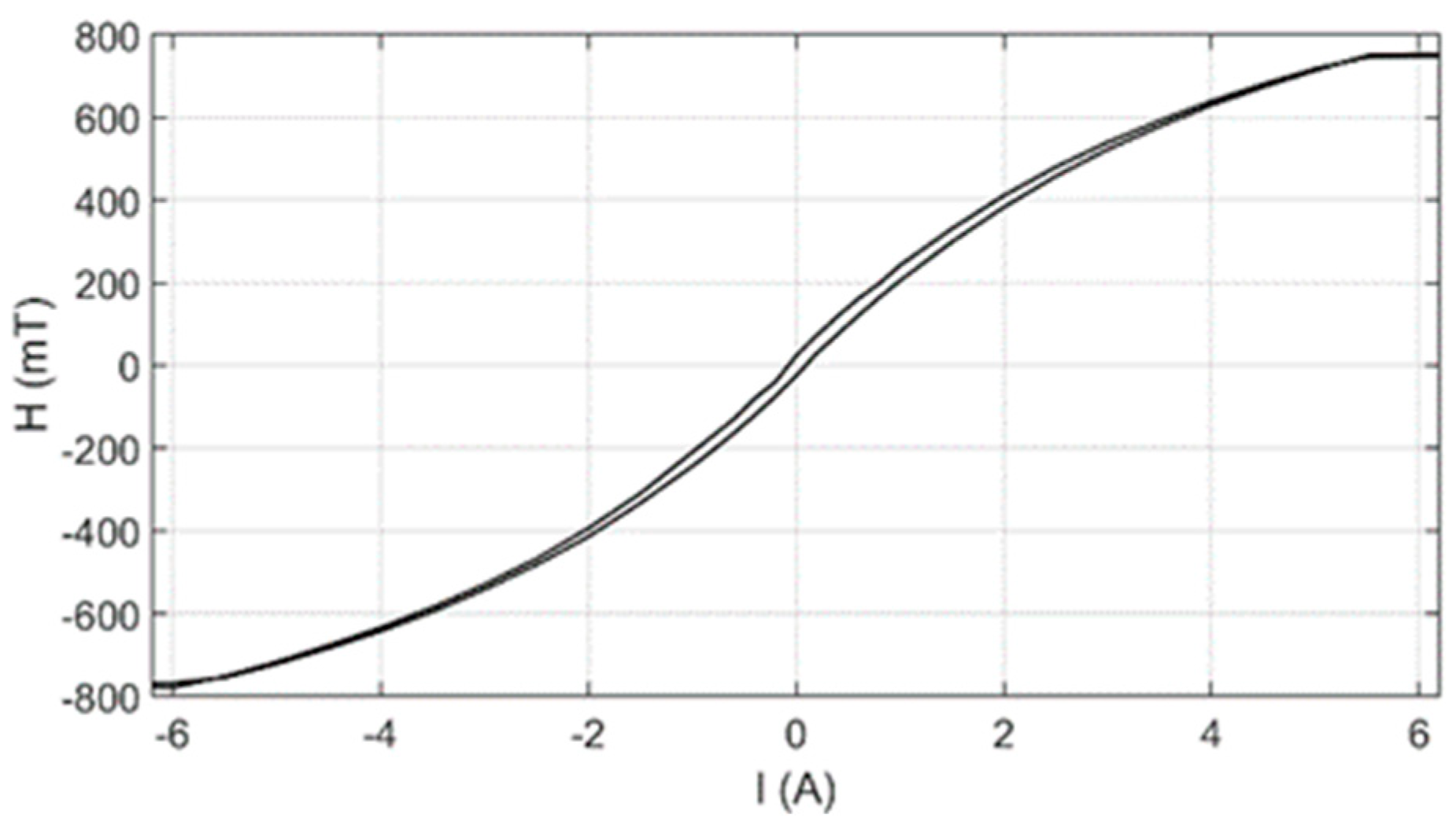
The magnetic field crossing the sample was measured by placing the gaussmeter probe between the sample and the plate.
Figure 12 shows the relationship between the magnetic field
H crossing the sample and the coil current intensity
I. The curve was detected up until a current intensity of about 6 A, after which no stiffness variation occurred.
5.2. Shear Characterization
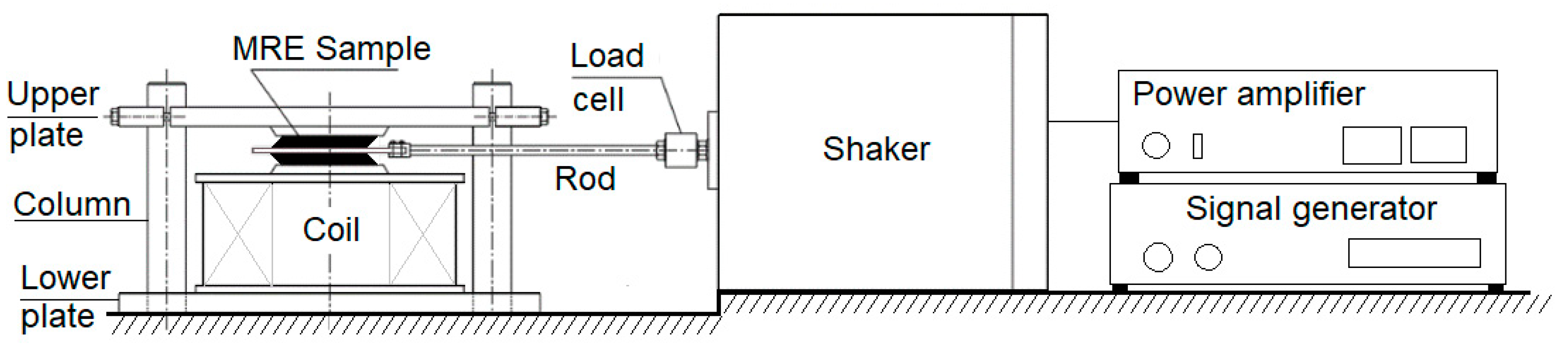
To characterize the MRE shear properties, the samples were tested under a constant compression load and variable shear excitation. The tests were conducted by placing two equal cylindrical samples (diameter: 50 mm; height: 6 mm) on opposite sides of a plastic platelet (
Figure 13). The platelet, connected to an electro-dynamic shaker by means of a rod, provided a shear harmonic load to the samples. The samples were axially deformed by adjusting the distance between the two contact surfaces, which were composed of the magnetic core of a coil and a plate whose position could be adjusted to assign a desired axial deformation. The corresponding axial load ensured that the elements did not slip under the transverse load transmitted by the shaker.
The test rig was equipped with an electromagnetic shaker (Bruel & Kjaer, mod. 4808), a coil able to generate 800 mT of magnetic field intensity, a load cell to measure the force exerted by the shaker (Dytran 6210S), an LVDT displacement sensor to measure the displacement of the shaker vibrating table (Inelta IGDL-5-k2455), and a force sensor resistor (FSR) that was placed between the specimen and the coil core to measure the axial load.
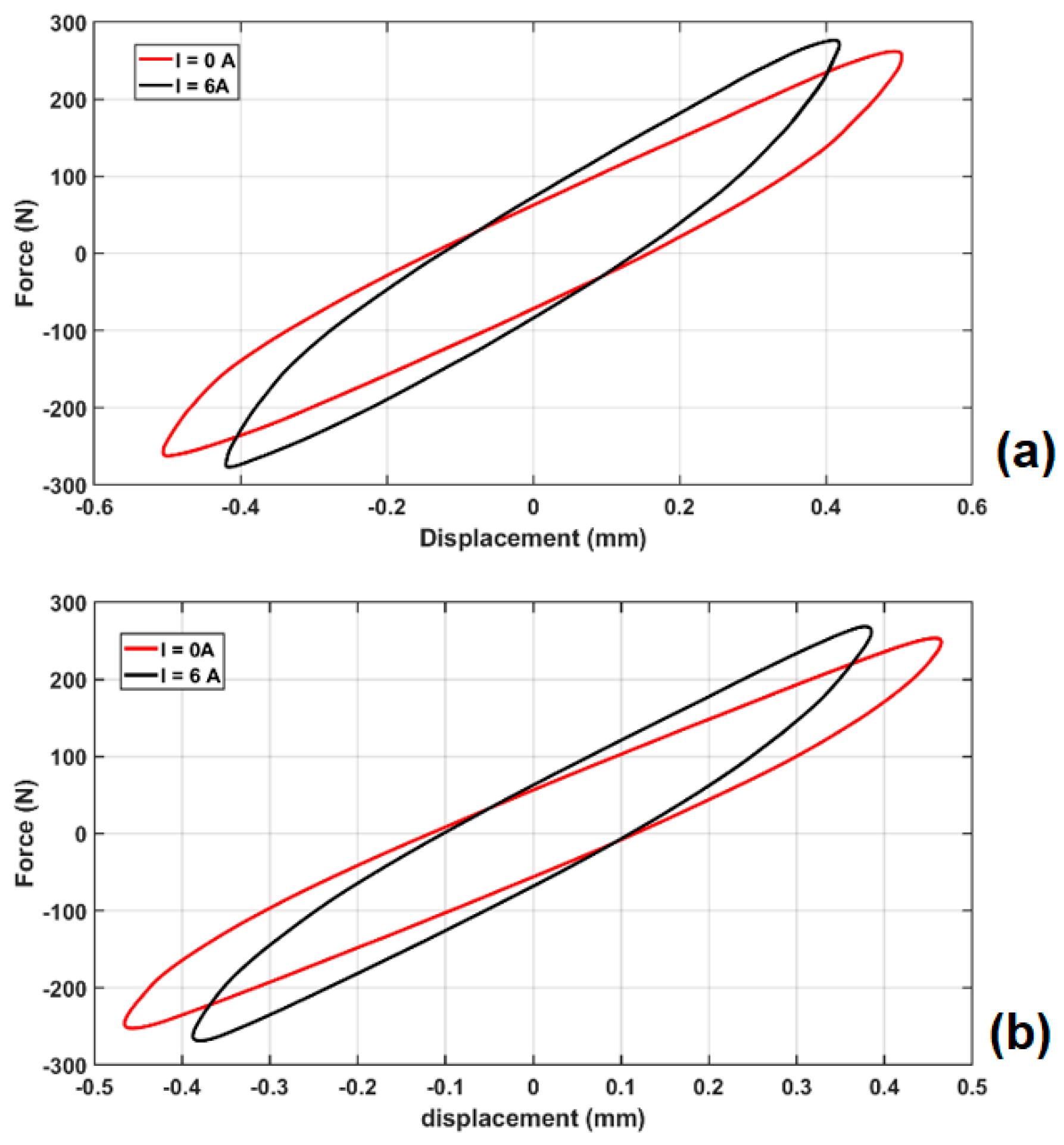
To highlight the influence of the forcing frequency and of the magnetic field intensity on the stiffness and damping properties of the MRE samples, several force–displacement diagrams were obtained for different operating conditions.
Figure 14 shows the test results performed at the forcing frequencies of 5 and 10 Hz with two different values of coil current intensity (0 and 6 A).
For each loop, the shear stiffness was estimated as the ratio between the maximum force and the maximum displacement, while the damping was evaluated through the cycle area by means of the expression: σ = A/(πωX2), where A is the cycle area, ω is the forcing circular frequency, and X is the motion amplitude.
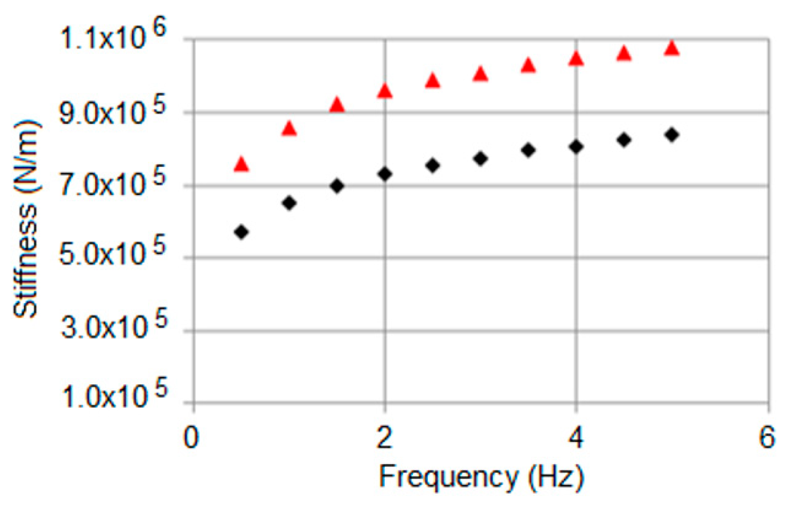
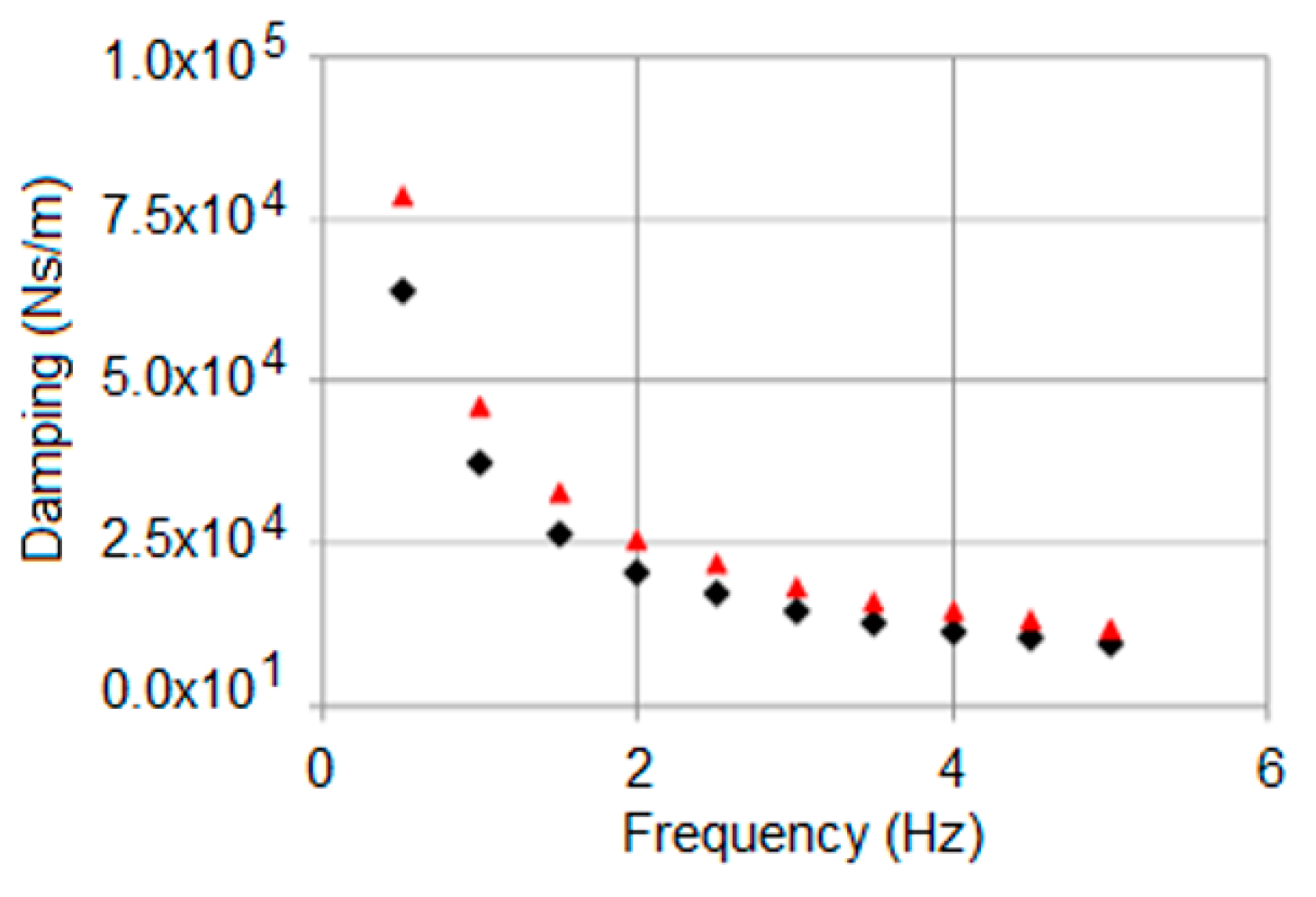
The results of all the tests are summarized in the following diagrams.
Figure 15 shows that the stiffness increased with the excitation frequency and with the intensity of the magnetic field. Furthermore, damping decreased with the excitation frequency (
Figure 16) and increased as the coil current intensity increased.
The diagrams show that it was possible to control the shear stiffness and damping of the adopted MRE material at low frequencies, whereas at higher frequencies it was only possible to effectively control the stiffness.
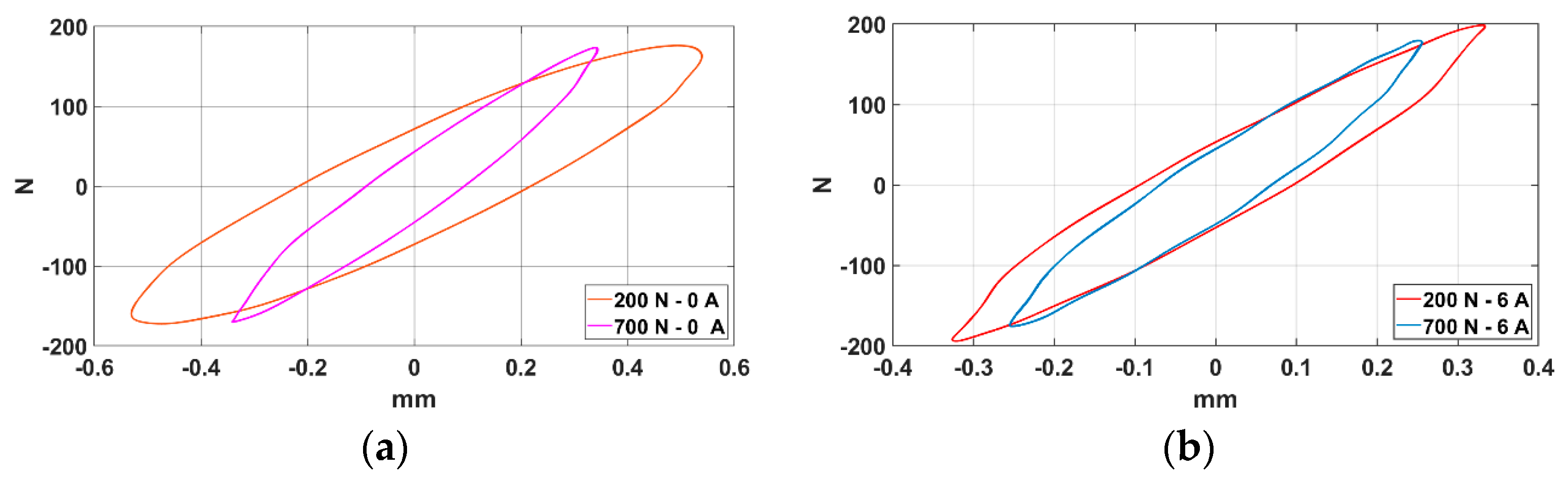
5.3. Axial Preload Influence on Shear Performances
Finally, several tests were performed to investigate the preload influence on the sample’s lateral stiffness. Force–displacements cycles (
Figure 17) were detected under a forcing frequency of 2 Hz with two preload values (200 and 700 N) and two different values of coil current intensity (0 and 6 A). The graph shows that there was a stiffness increase in both cases; the percentage increase was greater in the case of the lower preload (+82%), while it was lower in the case of the higher preload (40%).
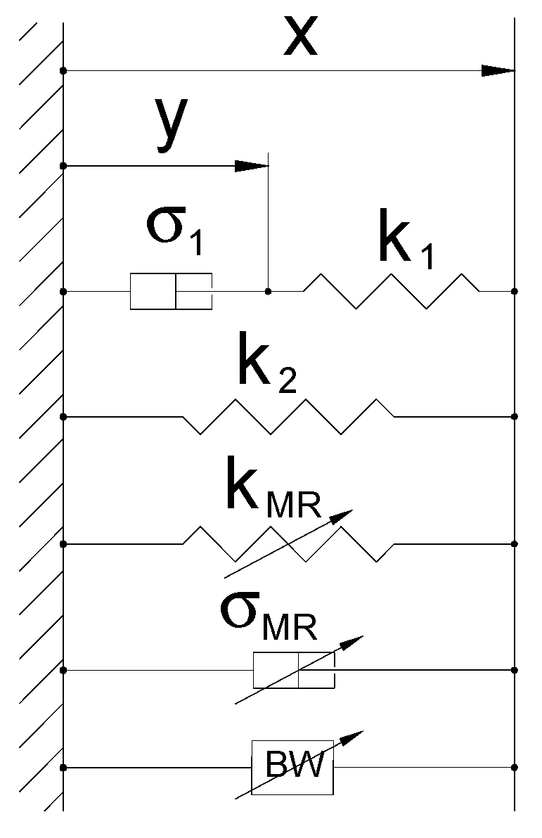
6. MRE Dynamic Model
To analyze the dynamic behavior of the MRE element, we propose a theoretical model [
20], whose scheme is reported in
Figure 18.
The proposed formulation uses the “standard linear model” to evaluate the linear visco-elastic behavior of the rubber. The hysteretic mechanism is well explained in [
21]; the correspondent component can be modeled in several modes; some recent models having high computational efficiency are now available as, for example, that based on the shape function and memory mechanism [
22] or the resistor-capacitor operator-based one [
23]. In the following, the Bouc–Wen model [
24] is adopted. The magneto-rheological effect is evaluated through the variable stiffness K
mr and the variable damping σ
mr and the restoring force is expressed by the following expressions:
The adopted hysteretic model is characterized by the normalized variable w and by the following four parameters: C, ρ, n, and αBW. Variable w assumes values confined within the range [−1, 1] and is defined by means of Equation (12).
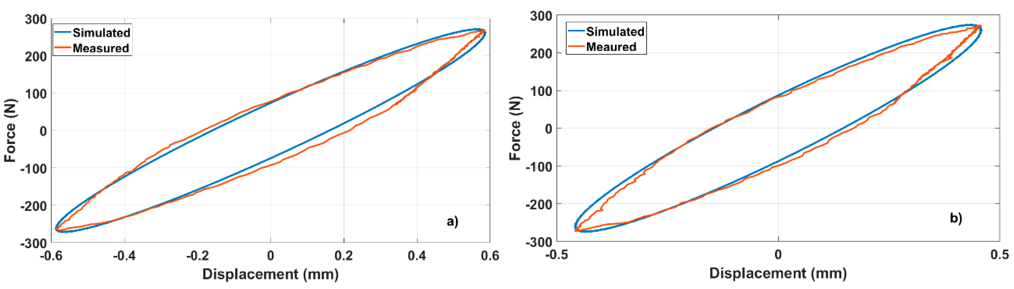
Figure 19 shows that there was a good agreement between the measured and simulated force–displacement cycles for the two different operating conditions.
7. Conclusions
The experimental tests conducted on the MRE samples, prepared with silicon elastomeric matrix and iron-carbonyl particles, were designed to evaluate their characteristics with respect to their potential application as vibration isolators.
A theoretical model determined the optimal volume fraction of the magnetic particles to maximize the magneto-rheological effect of the materials. Based on the theoretical results, several anisotropic MRE samples were prepared and tested using an experimental setup designed specifically for this study.
The experimental results demonstrated the wide variation in stiffness that can be achieved when such material is subjected to a magnetic field in both compression and shear tests; the material can, therefore, be used as a smart component of a semi-active vibration isolator.
Based on the test results, a visco-elastic model was developed to describe the sample’s dynamic behavior. This model can be used to develop a control algorithm for a semi-active vibration isolation system and to simulate its behavior.


