1. Introduction
Fluid overload is a clinical condition in which the accumulation of water in the body cannot be excreted. One of the main consequences of fluid overload is electrolyte imbalance, in particular of sodium (whose normal level is diluted), which possibly leads to digestive problems, behavioral changes, brain damage, seizures and sometimes even coma [
1]. In particular, the organs that lead to fluid overload are the kidneys and heart. Patients suffering from this pathological condition of fluid overload as the consequence of a renal disease or congestive heart failure need to be hospitalized and treated through dedicated extracorporeal blood purification therapies. In these treatments, patient’s blood, in which water and toxins are accumulated in excess, is externally drawn by a specific vascular access, and through an extracorporeal circuit, filtered and purified by a specific medical device called hemodialyzer. Finally, the purified blood is re-infused into the patient. The term “blood purification therapy” refers to an array of different techniques that are applied according to the specific clinical status. However, if the clinical aim is to remove excess water from patients, the specific technique is called ultrafiltration. Ultrafiltration aims at removing plasma water (the “ultrafiltrate”, or “UF”, in short) from blood through a semipermeable membrane, by means of a controlled pressure gradient [
2]. In contrast to therapies such as hemodialysis, hemofiltration or hemodiafiltration, isolated ultrafiltration, with no use of replacement fluid, does not allow for a direct reduction of uremic toxins concentration.
The actuation and control of all processes to be performed during ultrafiltration therapy are generally carried out by devices designed for use in a hospital/clinic setting, although also some devices exist with an option for ultrafiltration at home. None of these devices, however, are small and lightweight enough to be carried around while performing the treatment. In order to extract blood from a patient’s vascular circulation, a specific vascular access needs to be implanted. Except for the Artero-Venous fistula, the most used vascular access for this type of therapy is the dual lumen catheter [
3], which allows taking out and re-infusing blood to the patient, puncturing the vessel only once. Typically, the catheter is positioned in the jugular or femoral vein, which are large-caliber blood vessels, in order to guarantee adequate blood flows flowing inside the extracorporeal circuit. Blood from the catheter circulates into the disposable extracorporeal circuit that shall be adapted with the interface of the so-called “hardware” of the ultrafiltration machine [
2,
4]. Since blood exits from a vein and returns to the same vein, an external pump generating a pressure gradient is necessary in order to perform extracorporeal circulation. The core of the filtering process takes place inside a disposable component called a hemodialyzer or hemofilter; it is a device constituted of a semipermeable membrane that allows the filtration of plasma water and suspended particulates (among which electrolytes like sodium and potassium) and the retention of components that should not be removed from patients, like proteins and red blood cells. The membrane is made of thousands (between 2500 and 10,000) hemo-compatible polymeric hollow fibers, porous on the surface, through which blood flows. In the space between fibers, the fluid removed (ultrafiltrate) is collected and then displaced. The physical phenomenon of filtration is called ultrafiltration, because pores have an average diameter smaller than 100 nm. The driving force promoting the separation is the hydrostatic pressure gradient across the membrane; a negative pressure is applied in the ultrafiltrate compartment of the filter through a pump (the ultrafiltration pump) in order to generate a positive transmembrane pressure [
5].
Generally, ultrafiltration machines are bulky, and hence difficult to move. Furthermore, the management and set-up of these machines are not easy; consequently, a specialized and trained nursing and technical staff must setup and supervise each treatment procedure. Hence, ultrafiltration therapies generally require the hospitalization of patients [
6]. The scientific community is joining the worldwide effort to overcome these issues by providing novel technological solutions for the extracorporeal ultrafiltration therapy. The design of portable and wearable devices for continuous ultrafiltration that can be operated without direct medical control, and/or even possibly monitored remotely, seems the most viable option. It has been extensively recognized [
7,
8,
9,
10,
11,
12] that the great potential of such portable/wearable medical devices is that they can implement a mild blood ultrafiltration therapy out of hospital over an extended stretch of time (such as over a full day), making this process more similar to physiological body water removing, reducing total therapy costs and improving patient quality of life.
Several prototypes with similar therapeutic targets have been developed to date [
13,
14,
15,
16]. Although many of them have contributed to scientific progress in this field, some technological limitations still restrict their clinical application and their industrialization [
17,
18,
19]. Technological issues to be solved are mainly related to the requirements in combining safety for patients with miniaturization and low energy consumption. Hence, each new design must be developed with the greatest care to layout definition, to components choice, and to the implementation of a safe and robust control architecture.
A new mechatronic wearable device for extracorporeal blood ultrafiltration has been recently conceived by joint research project of theDepartment of Management and Engineering (DTG) of the University of Padova and the International Renal Research Institute of Vicenza (IRRIV) of the S. Bortolo Hospital. The device is named Rene Artificiale Portatile (RAP) after the Italian research program “Rene Artificiale Portatile”. Two papers describing the preliminary design of the RAP and of one of its more relevant components have been published recently [
20,
21]. This work provides a more in-depth description of the device, focusing on both the innovative aspects of its design which guarantee wearability, and on the control architecture. The results of preliminary in-vitro tests, which were performed to verify the safe and effective operation of the RAP device, are presented and discussed too.
2. Basic Operative Requirements
The RAP is intended to be a wearable/portable medical device that allows for safe out-of-hospital use under remote supervision. Consequently, the RAP should meet mandatory and strict requirements as formulated within international standards for safety and essential performance:
IEC 60601-1 “Medical electrical equipment—Part 1: General requirements for basic safety and essential performance”. This standard contains requirements for all medical electrical devices in general. These requirements pertain to safety aspects, human factor engineering and essential performance.
IEC 60601-2-16 “Medical electrical equipment—Part 2-16: Particular requirements for basic safety and essential performance of haemodialysis, heamodiafiltration and heamofiltration equipment”
IEC 60601-2-11 “Medical electrical equipment—Part 1-11: General requirements for basic safety and essential performance—Collateral Standard: Requirements for medical electrical equipment and medical electrical systems used in home care applications”. This standard applies to specific aspects of the safety and essential performance of medical electrical equipment intended for use in home care applications, usually without continual professional supervision and sometimes temporarily used in the clinical environment.
A multi-disciplinary mechatronic design approach has been adopted: issues related to different domains (medical, mechanical, electrical and electronic domains), together with their coupling and mutual effects, have been considered.
First of all, the device must be powered autonomously for a sufficient lapse of time to allow for the usual mobility habits of patients treated. Since the RAP is intended to be used for continuous ultrafiltration therapy, 24 h a day, 7 days a week, adequate energy storage should be available, with a careful design of components and algorithms as well, in order to reduce energy consumption and heat generation. Furthermore, miniaturization, ergonomics, and low weight are obviously of paramount importance and have been taken into account during all the design phases.
Another key feature is the capability of providing an automatic regulation of the clinical parameters during the whole treatment according to the medical prescription. Hence, the device controller must manage the therapy procedure and log all the significant clinical data, which should be accessible in real-time for monitoring purposes in the hospital, where a dedicated wireless communication system can be setup. The data recorded during the whole treatment should then be collected after its conclusion and stored by the hospital IT department. The logged data include all the data that are relevant to the regulation of the process, and to the monitoring of the correct operation, and therefore include pressures in the extracorporeal circuit (access, pre-filter, return, ultrafiltrate, transmembrane pressure), the prescribed blood, ultrafiltrate and heparin flows, the ultrafiltrate volume, the air temperature inside the device housing, the battery level, and the list of warning and errors generated during the therapy.
It is essential that the applied vascular access avoids infections and formation of blood cloths; it is also necessary that connection and disconnection are easy to perform. Moreover, the extracorporeal tubes through which blood flows must be made of anti-thrombogenic materials and the total priming volume should be as low as possible. The material of membranes must be non-thrombogenic too, for minimizing the risk of coagulation and blood losses. The device must be equipped with a dedicated pumping system able to remove a volume of ultrafiltrate comparable to the one physiologically removed from the kidneys over the same amount of time. Therefore, the volume of liquid to be removed in 24-h is estimated between 1.5 and 2 L.
When blood encounters artificial materials, the coagulation system of blood is immediately activated, inducing a coagulation cascade. In order to reduce this phenomenon during extracorporeal blood circulation, a controlled and continuous infusion of anticoagulation drugs, such as heparin, must be administered into the circuit as well. Considering a heparin infusion flow ranging between 500 and 1500 U.I./h, and adopting a solution where heparin concentration is 500 U.I./mL, the desired infusion flow range of the heparin pump is between 1 and 2.5 mL/h.
The design procedure has been preceded by a detailed risk management analysis carried out according to the international standards ISO 14971 and IEC 60601-2-16, in order to define the safety devices and components that should be included in the RAP, thus allowing elimination of the non-strictly necessary ones. Some of the selected components that have been integrated in the system have been chosen among commercially available ones, some others have been specifically conceived, designed and implemented. Furthermore, a specific initial effort has been devoted to the distinction between reusable and disposable components. Clearly, all components that have contact with the patient’s blood must be replaced after each use. This requirement has been addressed, as will be specified in
Section 3, through a specific layout design.
The list of the strictly necessary components of the RAP includes:
an air sensor to detect air bubbles in the blood line;
a blood leak detector (BLD) to detect blood loss due to membrane rupture;
three pressure sensors (access pressure, pre-filter pressure and return pressure sensors) to detect disconnections or blood coagulation;
a pressure sensor in the ultrafiltrate line to detect coagulation in the filter;
a fluid balance monitoring system to check the plasma water volume removed from the patient;
a temperature sensor to monitor excessive temperature variations;
a sensor detecting when the heparin reservoir is empty.
Furthermore, a clamp (safety valve) capable of automatically occluding the disposable circuit where blood flows is included in the design. This avoids any undesired infusion (e.g., clots, air) into the patient. It must be placed immediately before the blood return side of the catheter and must be operated whenever a safety hazard is detected. Since commercially available safety clamps are unsuitable for portable/wearable devices because they are large, heavy and high-power consuming, a customized and innovative design has been specifically applied for this component [
21].
3. Layout of the RAP
The first and more evident design goal for the rap is keeping the overall size to a minimum [
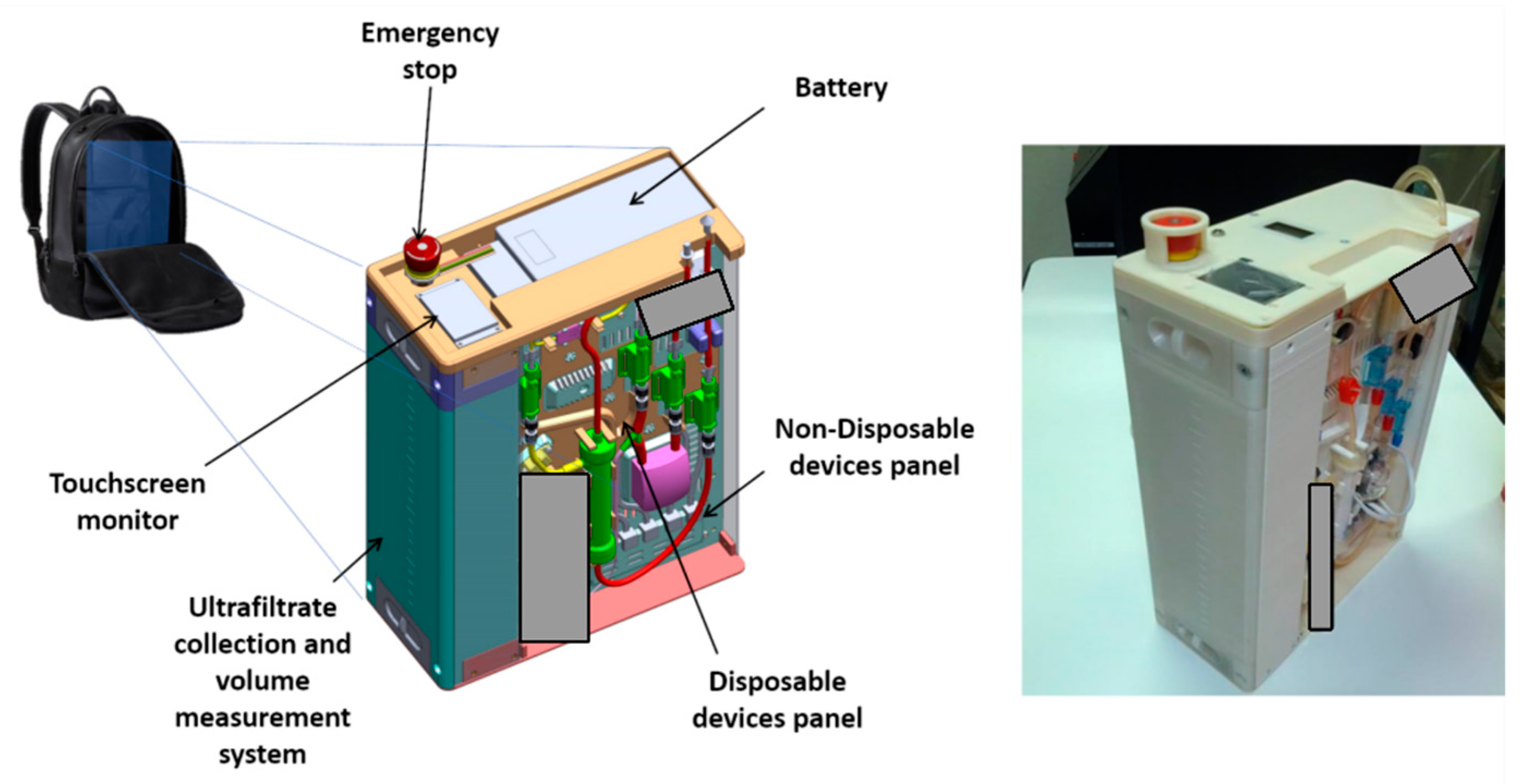
15]. This feature is dictated by the choice to improve the portability of other existing devices, by ensuring that the layout fits a backpack or a trolley case.
Figure 1 shows a 3D - sketch of the virtual prototype, as well as a picture of the first working prototype of the device. The latter has been built using additive manufacturing technology. Some components are masked in the pictures since their patentability is currently under investigation.
The main feature of the design is the ‘multiple layer’ paradigm, which represents a significant departure from the more common ‘single layer’ paradigm used by most existing devices for ultrafiltration, such as the ones that are worn as a belt or as a sling [
8]. This design introduces several advantages, both for patients (ease of carrying and use, both when standing or seating) and for healthcare professionals (simple installation of disposable components, easy setup of the clinical procedure, easy maintenance).
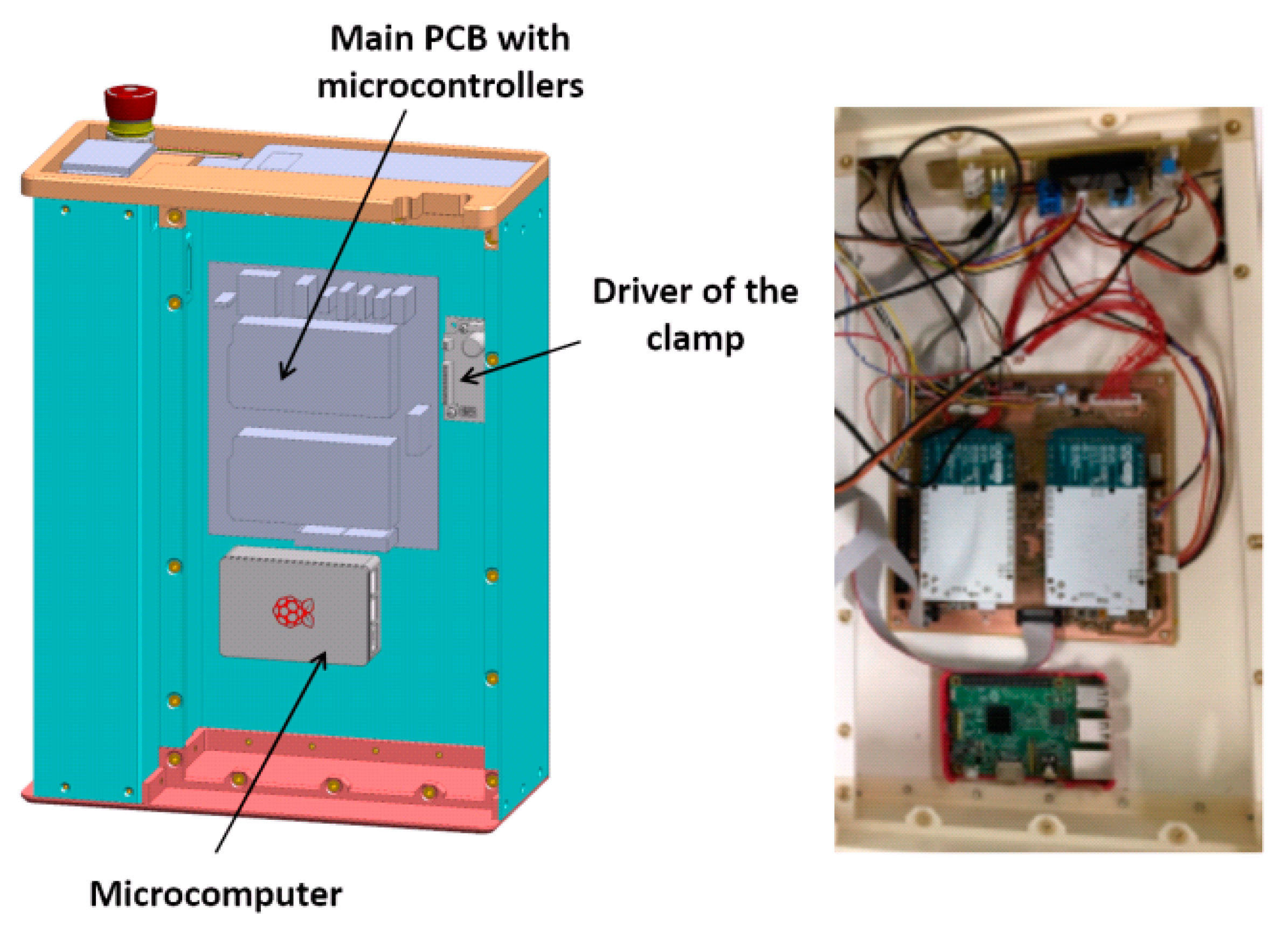
The mechanical layout is split into three layers, each one hosting a set of components. The first layer, which can be identified as the ‘backbone’ panel, hosts the main electronic components, including two microcontroller boards and a single-board microcomputer. The functionality of these devices, which implement the system control architecture, will be described in detail in
Section 6. The CAD sketch and a picture of the first layer are shown in
Figure 2.
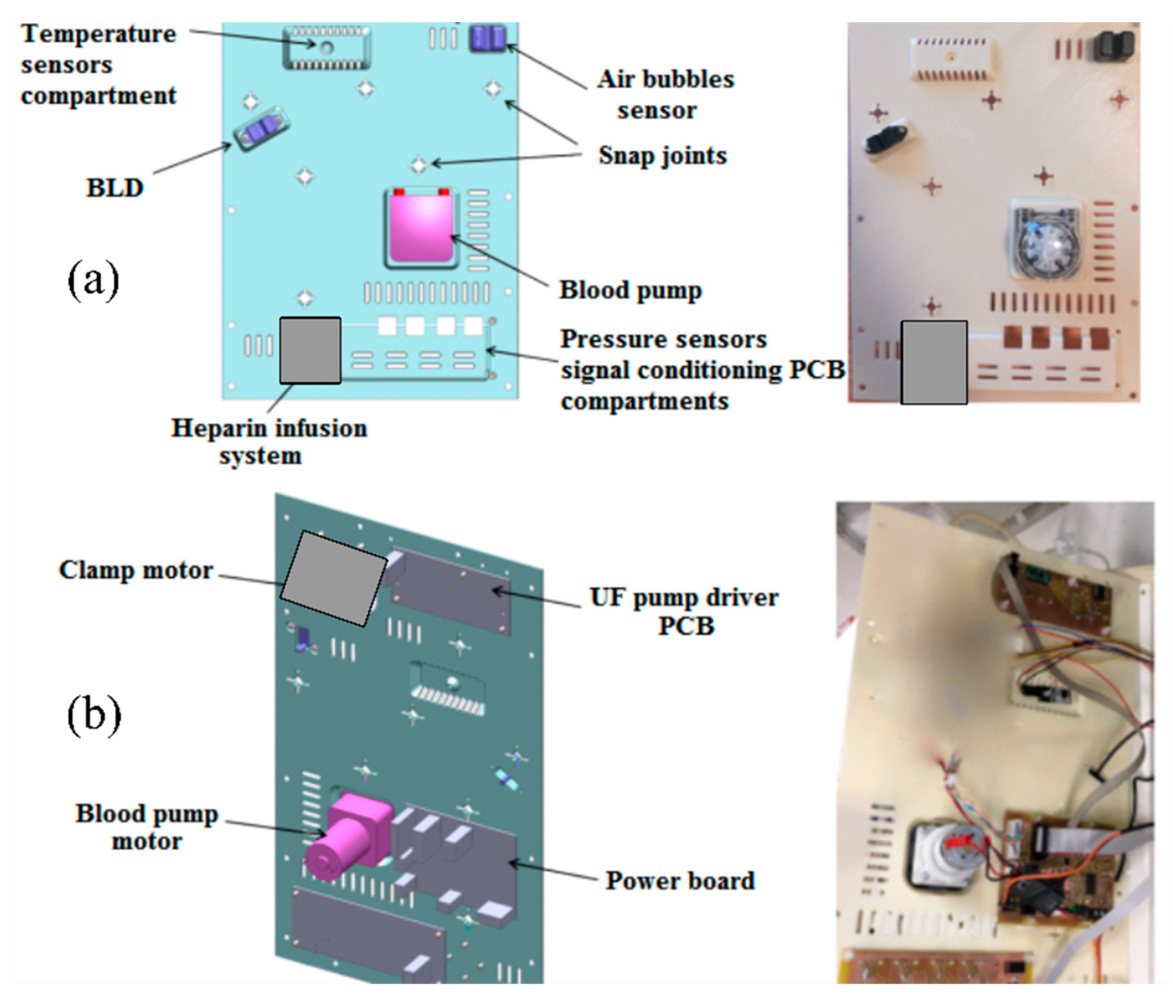
The ‘intermediate’ panel hosts other non-disposable components. The main ones are the peristaltic blood pump, the heparin infusion system, the custom-built electromechanical safety clamp, the air sensor, the temperature sensor and the BLD. These components are visible on the front of the panel, as shown in
Figure 3. Looking at the backside of the panel, the ultrafiltrate pump driving circuit and the board for the signal conditioning circuit are visible.
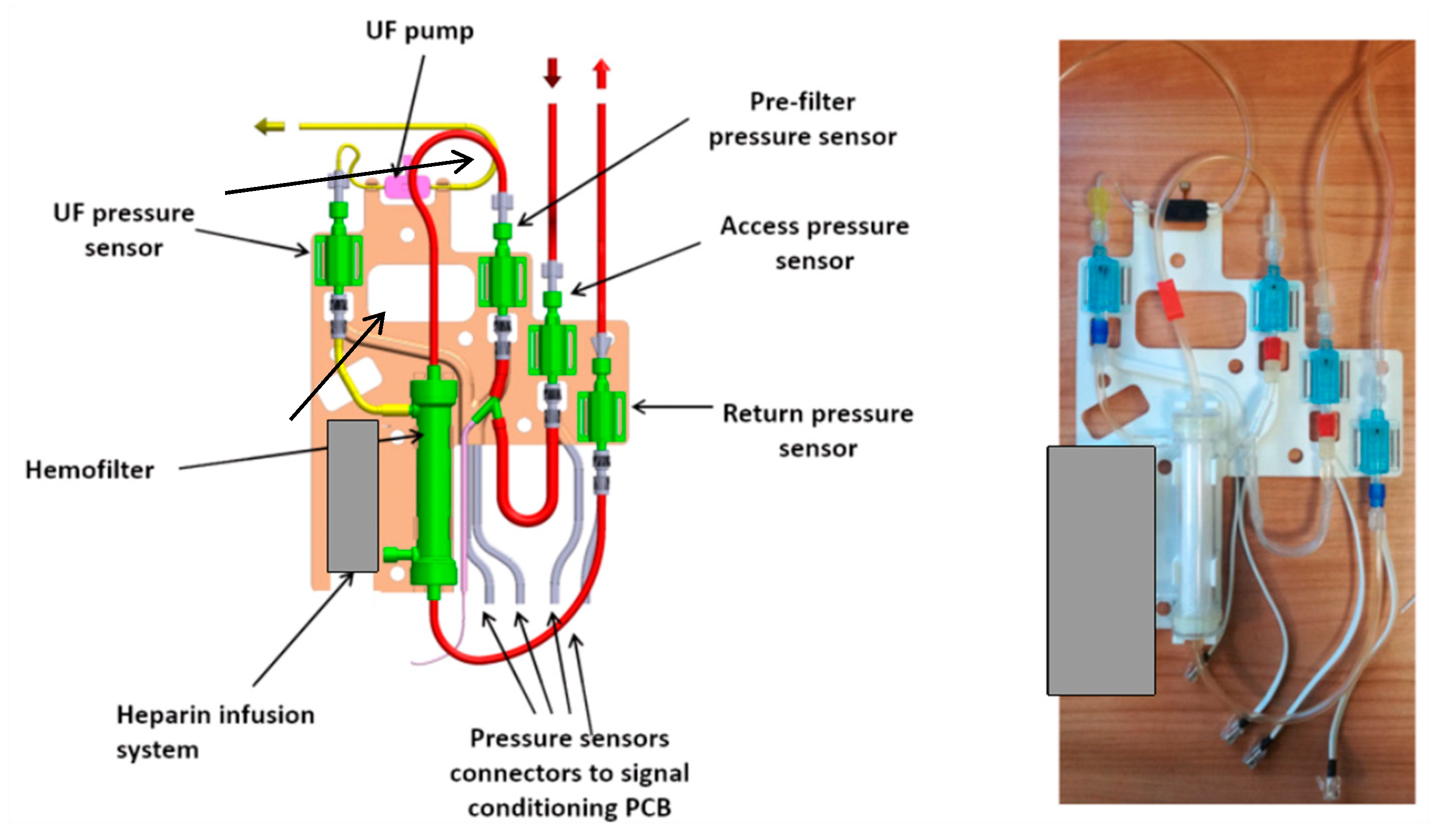
The third or external layer of the RAP hosts all the disposable components (the priming volume, included the filter, is almost 60 mL): the polyvinylchloride blood circuit, the hemofilter (priming volume 33 mL), the disposable elements of the heparin infusion system, the pressure sensors and the piezoelectric pump that displaces the ultrafiltration liquid.
The external layer, as shown in
Figure 4, is designed as a ‘replacement kit’ or as a ‘cartridge’ system, that can be snapped in the device during the preparation of each treatment, and quickly disconnected and disposed after the use. The same figure also lists all the components of the blood line circuit.
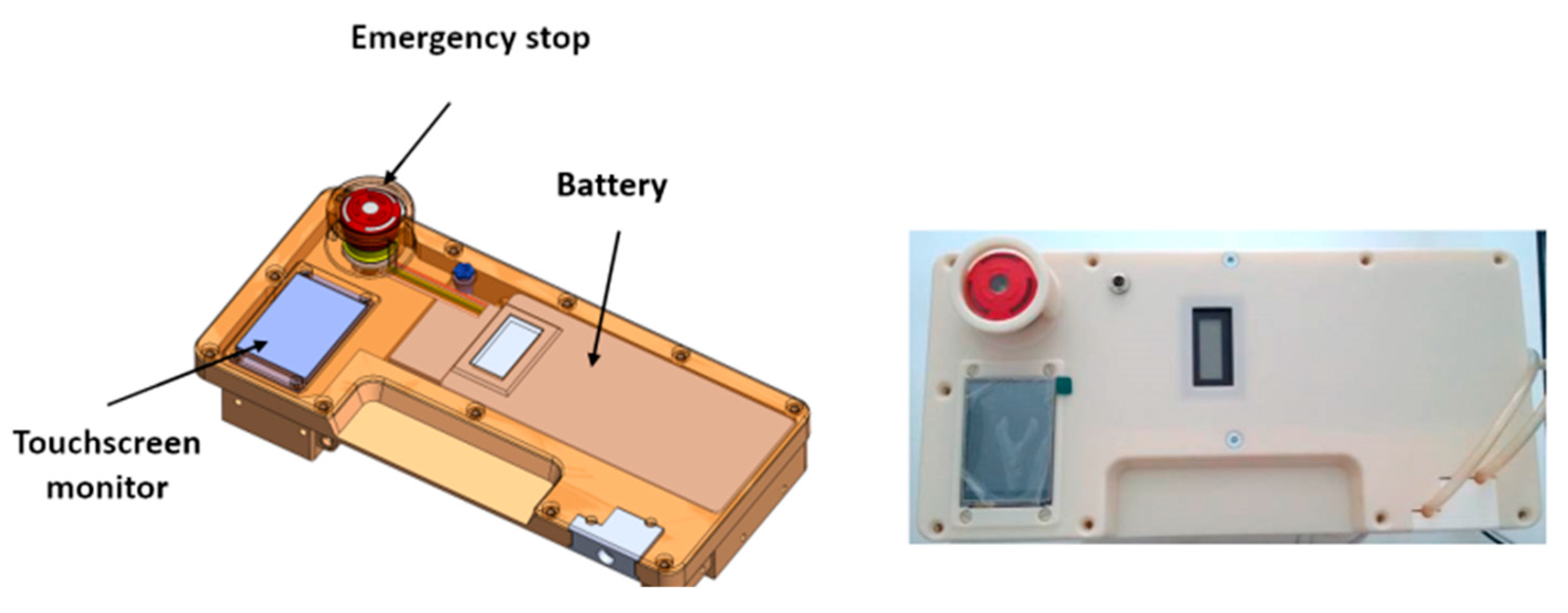
The battery that powers the RAP is located in the cover panel (
Figure 5), which hosts also a touchscreen display and an emergency stop button.
The power source is a lithium battery with 75.5 Wh capacity, equipped with USB connection for quick charge technology. According to the results of several experimental trials, the average electric power consumption is equal to 13.9 W, and therefore the chosen battery can provide up to 5 h of running time. The design, however, gives the possibility of extending running time simply by including a small backup battery, allowing a “hot swap” main battery replacement without interruptions to the therapy, or by plugging the RAP into an AC outlet to recharge the battery.
The LCD touchscreen display mounted on the cover panel can be used for the treatment setup by healthcare professionals, as well as for monitoring of the main treatment parameters by patients. Patients can verify the correct operation of the device or the presence of a warning (e.g., by a warning message, such as ‘empty the UF tank’), they can pause/resume the therapy, or they can follow the instructions prescribed by the therapeutic procedure. The LCD display, which is wired to the main board, can also be removed from its housing and placed on a shoulder strap for an easier use or monitoring.
The ultrafiltrate liquid is collected in a tank that is located on the left side of the device (see
Figure 1). The tank, which can be easily removed to be emptied, has a capacity of 2.2 L and is equipped with a customized measurement system. Ultrafiltrate volume, which is measured by the RAP control architecture, is one of the therapy key parameters, and therefore must be monitored continuously during the whole clinic procedure.
The overall dimensions of the prototype are 405 by 300 by 140 mm, and the total weight is slightly below 5 kg with an empty tank, 7.2 kg with a full ultrafiltrate tank.
4. Control Architecture
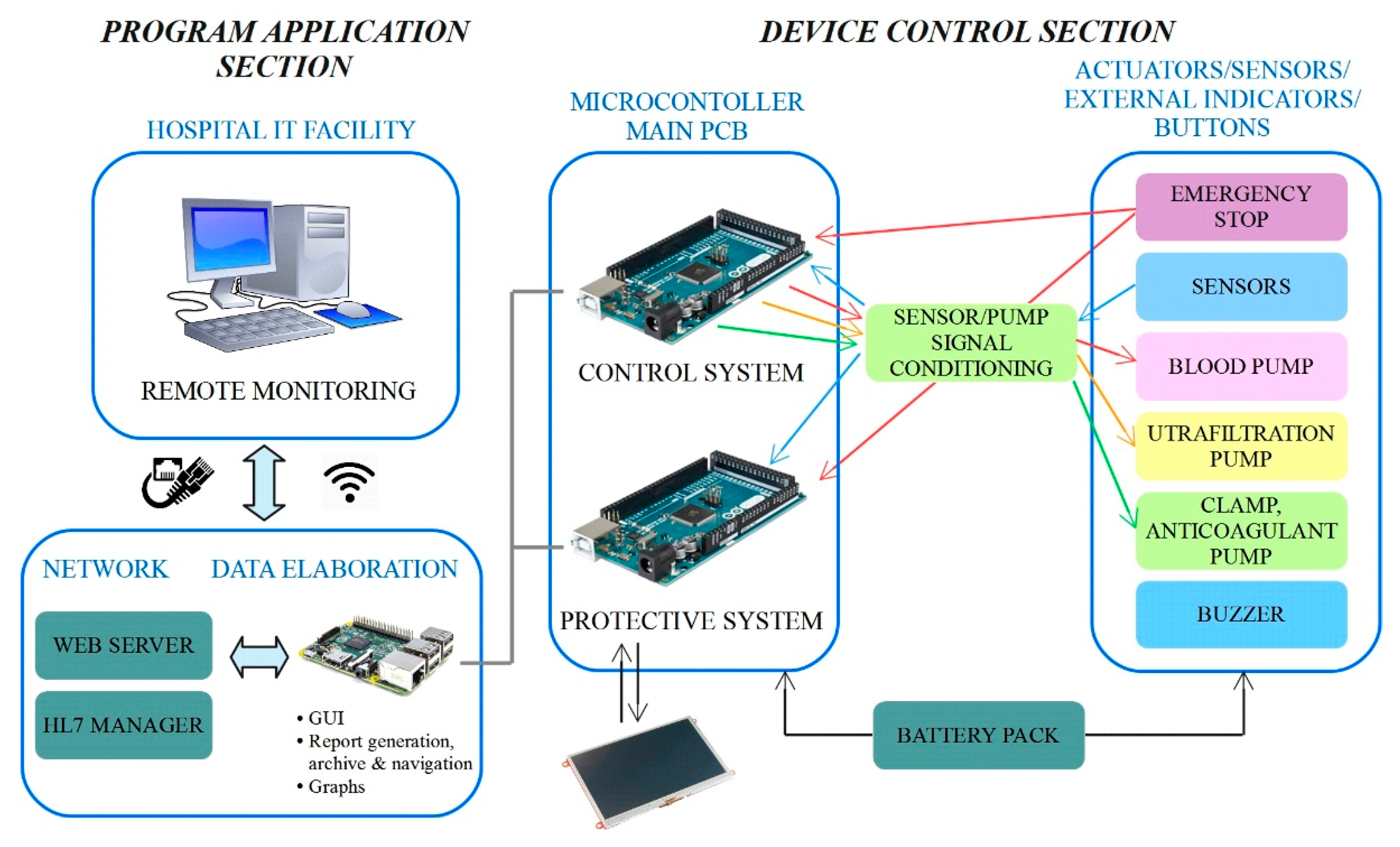
The control architecture adopted for the RAP is shown in
Figure 6.
The architecture has been carefully designed to meet both the restrictive requirements imposed by the application (the development of a miniaturized, energy efficient and wearable device which could be monitored remotely) and those imposed by the safety regulations of medical devices with the aim of minimizing risk for patients. The architecture can be split into two main sections, named the “program application section” and the “device control section”, according to
Figure 6. The main components of such an architecture are the microcomputer and the two microcontrollers boards, which work together to handle the RAP functionalities.
The core of the program application section is run by the embedded Raspberry PI microcomputer, which runs the therapy management application, and implements the top layer of the software that runs on the RAP. The main tasks of the program application section are:
management of communication with the device control section
management of communication with an external PC through a web server and through the HL7 protocol
logging of the data collected during the therapy
management of treatment prescription and its transfer to the device control section
management of the Graphical User Interface (GUI), accessible locally or through a wired/wireless LAN connection as a web page, that can be used for treatment set-up in hospital and for real-time monitoring of treatment data.
HL7 (Health Level 7, standard ISO 16527) is a specific standard protocol for exchanging information between medical applications. This standard defines a format for the transmission of health-related information, and therefore is commonly supported by the IT facilities of hospitals.
The device control section represents a lower layer of the control architecture that runs on the RAP, since it acts as an intermediate level between the ‘high level’ therapy management handled by the onboard microcomputer, and the ‘bottom level’ which includes the sensors, actuators, the LCD display and the power supply. The control section, however, does not simply act as a driver, since it takes care of running the actual control loop which ensures safe and correct operation of the RAP.
Each treatment is customized on the basis of the medical prescription through the GUI that runs on the Raspberry PI microcomputer, which translates them into a cluster of numeric set-points, which are in turn transferred to the device control section. Data sent from the device control section to the program application section include the key information on the status of the system (pressure values, amount of the ultrafiltrate removed, etc.). Such communication is performed through a USB connection between the microcomputer and the two microcontroller boards.
The redundancy of the control, which is a strict requirement imposed by the safety regulations, is implemented within the device control section. Each microcontroller independently performs the reading of all the sensors, and data are continuously compared to detect any possible mismatches between the two readings. The detection of a sensible discrepancy between readings, which suggests a measurement failure, triggers an emergency stop of the treatment. An emergency stop can also be triggered by the emergency button (also read by both microcontrollers), by the microcomputer, by the LCD, or by the device control section when a potential hazard is detected. It must be pointed out that the two microcontrollers run two different software codes, since not all operations are performed in a redundant fashion. Running two different codes also avoids the possibility of identical, and therefore undetectable, errors in both applications.
The two microcontroller boards are labelled as ‘control system’ and ‘protective system’ (see
Figure 6) to highlight their different purposes. The ‘control system’ completely manages the ultrafiltration therapy, by reading the signals from the sensors and by providing the correct set points to the pumps. Sensor data are also transmitted to the microcomputer that stores them in a data log file, allowing complete monitoring of the therapy. The second microcontroller board, that is, the ‘protective system’, takes care of handling safety, mainly by performing the redundant reading of the signals from the sensors and performing the comparison with the data generated by the other board. In case of out of range measures or mismatches between the measures read by the two microcontrollers, a safety procedure is activated, imposing treatment interruption by stopping the pumps and closing the electro-mechanical safety clamp. At the same time, one bit of the communication array is set at a high logical level in order to communicate the current status immediately and to display an alarm message on the GUI. Furthermore, the protective microcontroller is connected to the LCD touchscreen, through which patients can immediately check the therapy status. The safety procedure can also be activated manually, by the emergency stop button placed on the top of the device and any alarms or warnings detected by the system are signaled through a buzzer.
In order to further improve the overall system safety, a watchdog hardware component has been fitted to continuously check the microcomputer status, ensuring that none of the microcontroller boards ‘freeze’.
An accurate development of the control logic has been carried out as well; it has been developed based on clinical requirements, risk analysis, and after investigating thoroughly the behavior and the performances of some standard and reliable existing extracorporeal blood ultrafiltration machines.
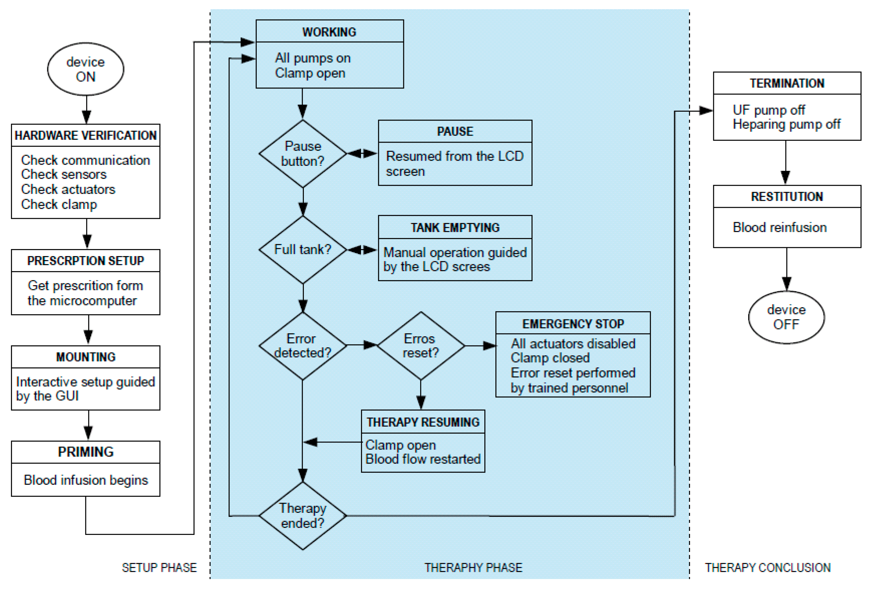
The control logic has been structured in three main sequential operational phases to be performed. They are:
Setup phase;
Therapy phase;
Termination phase.
All of these phases have been translated into software routines running on the microcontrollers and the microcomputer. Each phase has been further divided into relevant clinical procedures and technical steps to be executed. A graphic overview of the sequence of operations included in each phase is shown in
Figure 7.
The setup phase consists of the following clinical procedures:
switching on of the device: during this state, the system verifies the communication between the two microcontrollers and the microcomputer;
mounting of the disposable components (‘cartridge’) on the non-disposable panel. Such a procedure needs to be performed in hospital by a trained healthcare professional;
prescription of the therapy (remotely adjustable only by the physician);
priming of the extracorporeal circuit: this is the most important procedure to be performed in the setup up phase. The automated priming is performed in order to fill the extracorporeal circuit with physiologic solution, remove all the air from the circuit, deposit some heparin along the inner surfaces of the hemofilter and tubes, and check if the circuit and the sensor have been connected properly;
connection of the circuit to the patient catheter.
The setup phase is handled by the microcomputer, since it requires the input of several clinical parameters to correctly define the treatment according to the medical prescription. Such an operation is performed at the hospital by the healthcare assistants, who also take care of performing blood circuit priming, during which the conditions for starting extracorporeal blood circulation is ensured.
The second operational phase is the one corresponding to the ultrafiltration therapy. This phase is supervised by the program application section, that is, by the microcomputer, but theoretically the device control section could run the whole phase autonomously.
The first procedure to be performed in this phase is to initiate extracorporeal blood circulation, therefore starting the actual ultrafiltration treatment. If a hazardous situation is detected, the device automatically enters the state of alarm. In this state, the device automatically reacts by stopping the pumps and occluding the clamp based on the type of alarm and its risk. The alarm can be reset; if the problem is solved, the therapy can be carried on, otherwise the system re-enters the state of alarm.
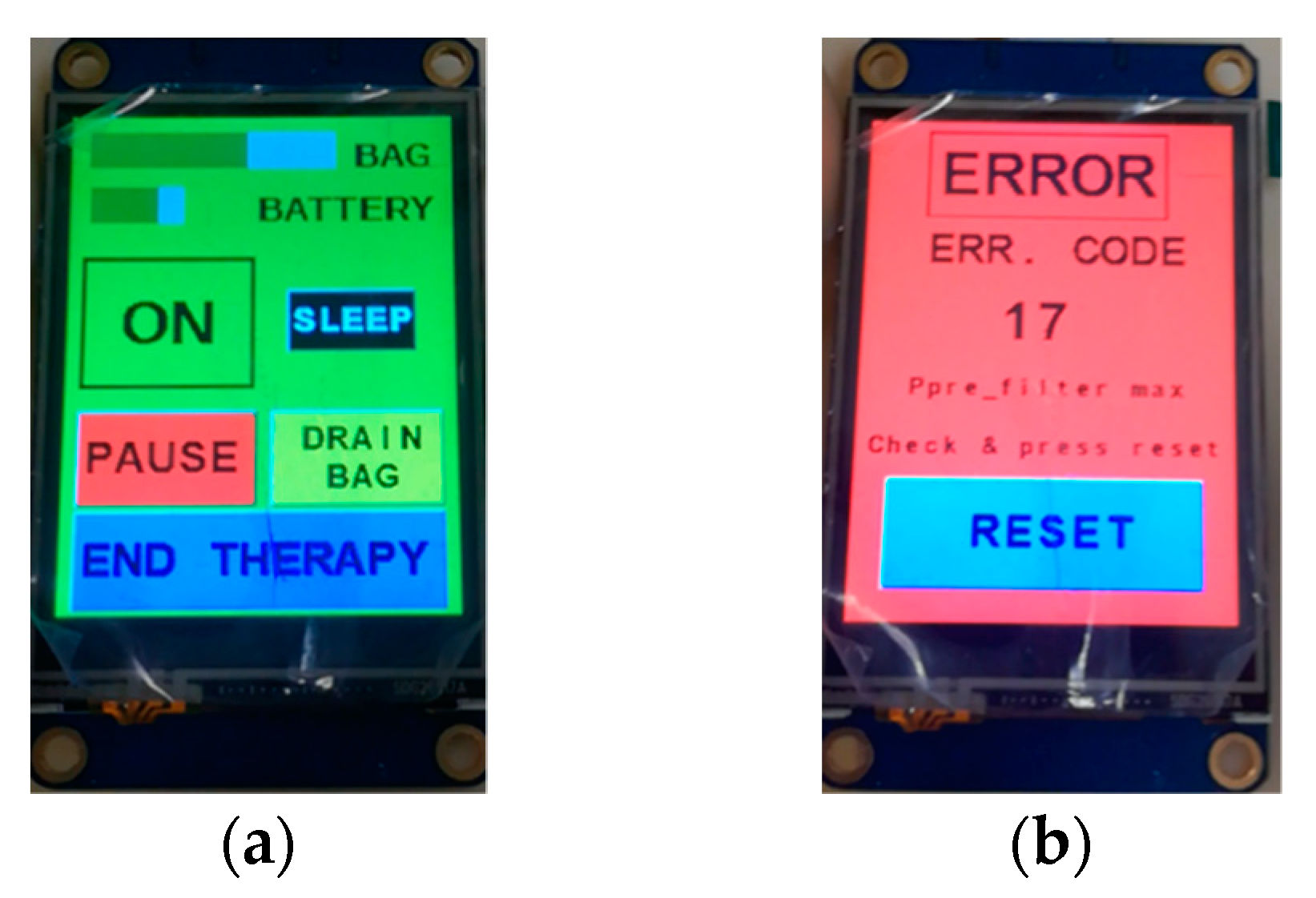
The therapy phase can be paused at any time by stopping the blood pump. This can be done easily by touching a dedicated key on the touch sensitive LCD panel, or alternatively, through the GUI running on the microcontroller. The same methods also allow the therapy to resume. If the duration of the “pause” phase lasts more than 2 min, the machine raises an alarm for prolonged blood stagnation. The same check is made when the emergency stop button is pressed.
Figure 8a shows examples of messages appearing on the LCD panel during a therapy; information fed back to patients includes the battery charge status and the amount of liquid accumulated in the ultrafiltration tank. The ‘drain bag’ button should be pushed just before manually emptying the tank in order to set up the device properly. The detection of a safety hazard triggers the immediate stop of the procedure, which is then signaled on the LCD screen, as can be seen in
Figure 8b. Each possible safety hazard is identified by a numerical code, and each error event is logged.
The third and final phase of the therapy can, again, be triggered through either the LCD or the GUI; during this phase ultrafiltration ceases. It should be highlighted that this phase must be carried out in the hospital with a trained nurse who has to perform all the needed operations, in the proper order, as listed and guided by the GUI. At the beginning of the termination phase all pumps are stopped, thus ceasing ultrafiltration. After that, the blood along the external circulation line must be reinfused into the patient. To do this, the access line needs to be disconnected from the catheter and connected to a physiological solution; the RAP blood pump is then re-activated until all blood is removed from the circuit. The device can then be turned off, and the return tube can be disconnected from the catheter.
5. Preliminary Validation Tests
Preliminary in vitro tests have been carried out on the RAP to experimentally verify the effectiveness of the device components and of the device as a whole. A dedicate test bench platform was used for this purpose. The tests aimed to verify the following features of the RAP:
reliability of pressure measurements in the RAP, by comparing the estimation with the measured values and with those of the test bench platform;
reliability of the blood flow estimation procedure implemented in the RAP, by comparing the values measured by flow meters installed in the test bench platform;
reliability of the temperature sensor used in the RAP, by comparing the measured values with those of the test bench platform;
reliability of the ultrafiltrate measuring system used in the RAP, by comparing the estimated values with those obtained by an electronic scale;
reliability of the power-bank battery used to supply the RAP for a duration of at least 5 h;
mechanical resistance of the disposable tubes of the extracorporeal circuit for a duration of at least 5 h;
biocompatibility, in terms of possible cytotoxicity induced by contact with all the disposable components of the circuit that will get into contact with blood.
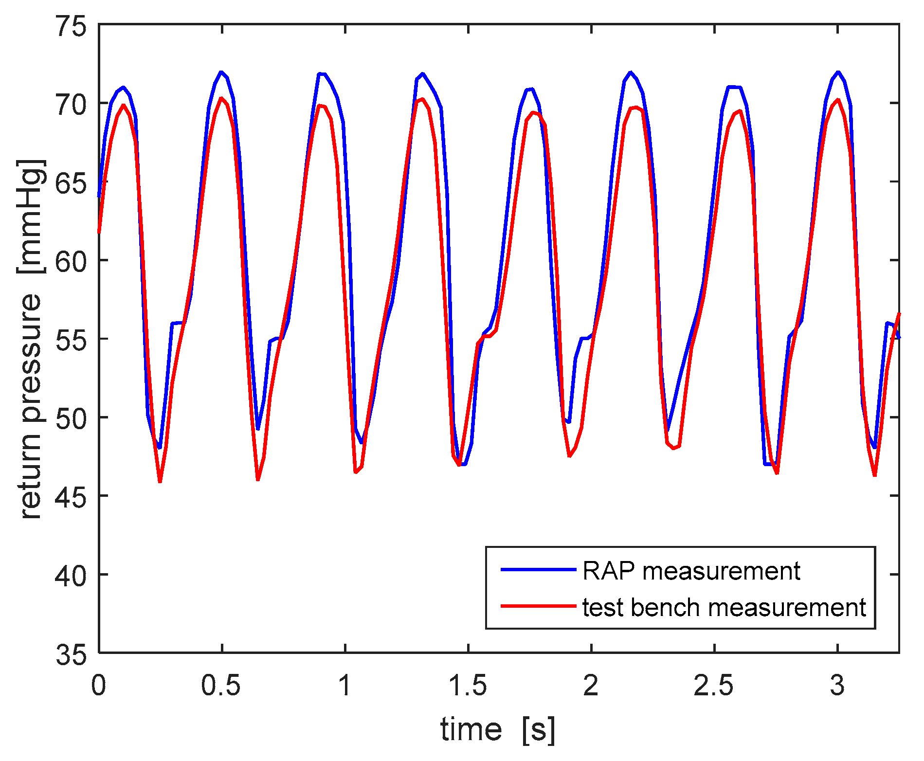
All tests have been carried out by circulating 0.9% saline solution, with a density almost identical to water. The frequency of acquisition of pressure values measured by both devices has been equaled (20 Hz) in order to compare the two signals properly.
Figure 9 shows the typical peristalsis-induced trend of the return pressure: the data collected by the test bench pressure measuring system are consistent with the ones measured by the RAP. This consistency has been checked, with similar results, for all three RAP pressure sensors (access, pre-filter and ultrafiltrate pressures). Based on these results, the choice of the pressure sensors and the signal conditioning procedure adopted in the RAP have been considered suitable.
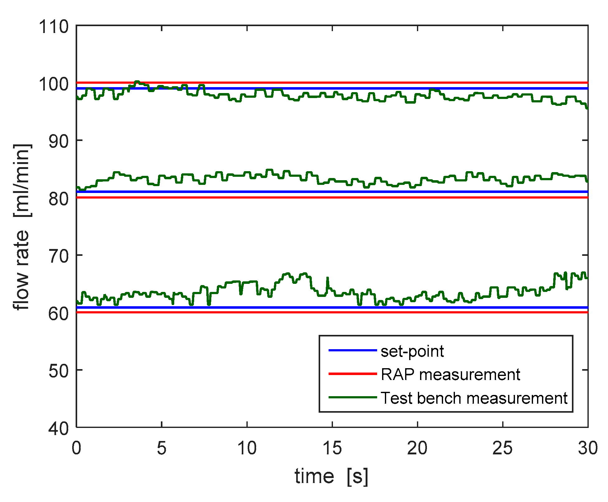
As a second step, the reliability of the blood flow estimation system used in the RAP, which is based on a real-time elaboration of the amplitude and frequency of the pre-filter pressure signal, has been verified.
Figure 10 shows the comparison between the blood flow rate estimated according to the algorithm run by the RAP and the one measured by the test bench for three different set point values (60, 80 and 100 mL/min). The flow rate estimated by the RAP (in red) slightly differs from the one measured by the flow meter. In particular, the worst-case estimation error is equal to 9.12%, which is well below the accuracy limits highlighted by the risk analysis process.
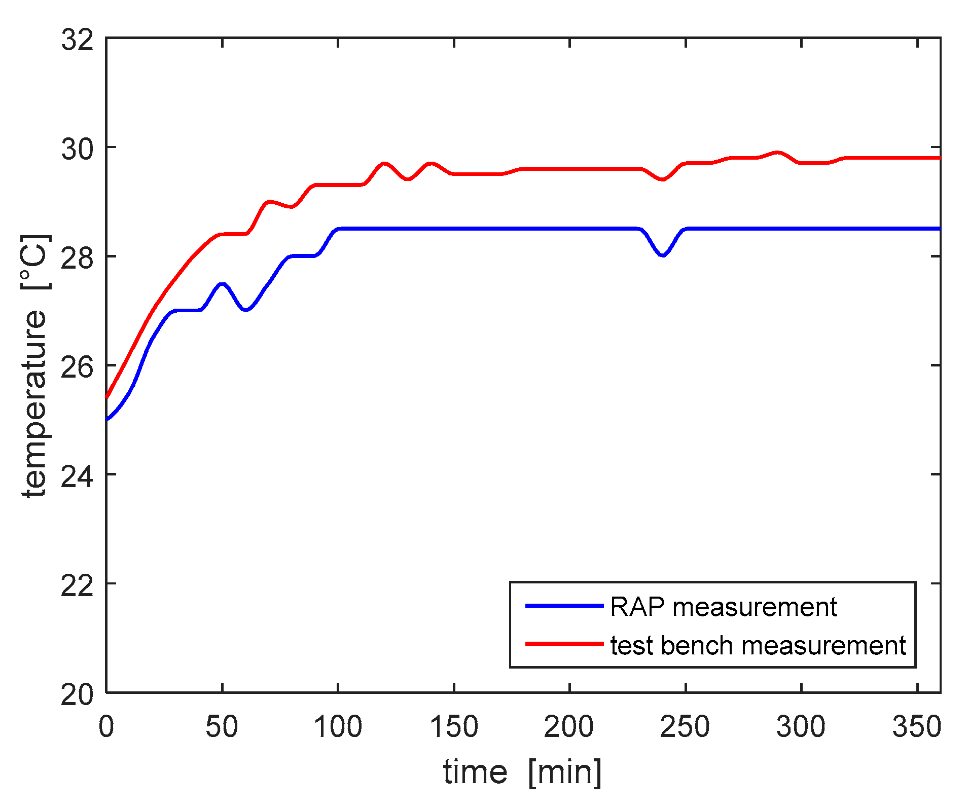
Subsequently, the temperature sensor of the RAP, which measures the temperature of the air inside the device housing, was validated. Temperature values have been recorded every 10 min for a total treatment duration of 5 h and 12 min.
Figure 11 shows the comparison of temperature values read by the two measurement devices, with a room temperature equal to 25.5 °C. The maximum percentage error recorded was 5%; according to the results of the risk analysis this measurement error does not provide any actual safety hazard. The temperature measurements show that the initial temperature, 25 °C, increased to the stable measure of 30 °C within the first hour of operation, thus no overheating was detected.
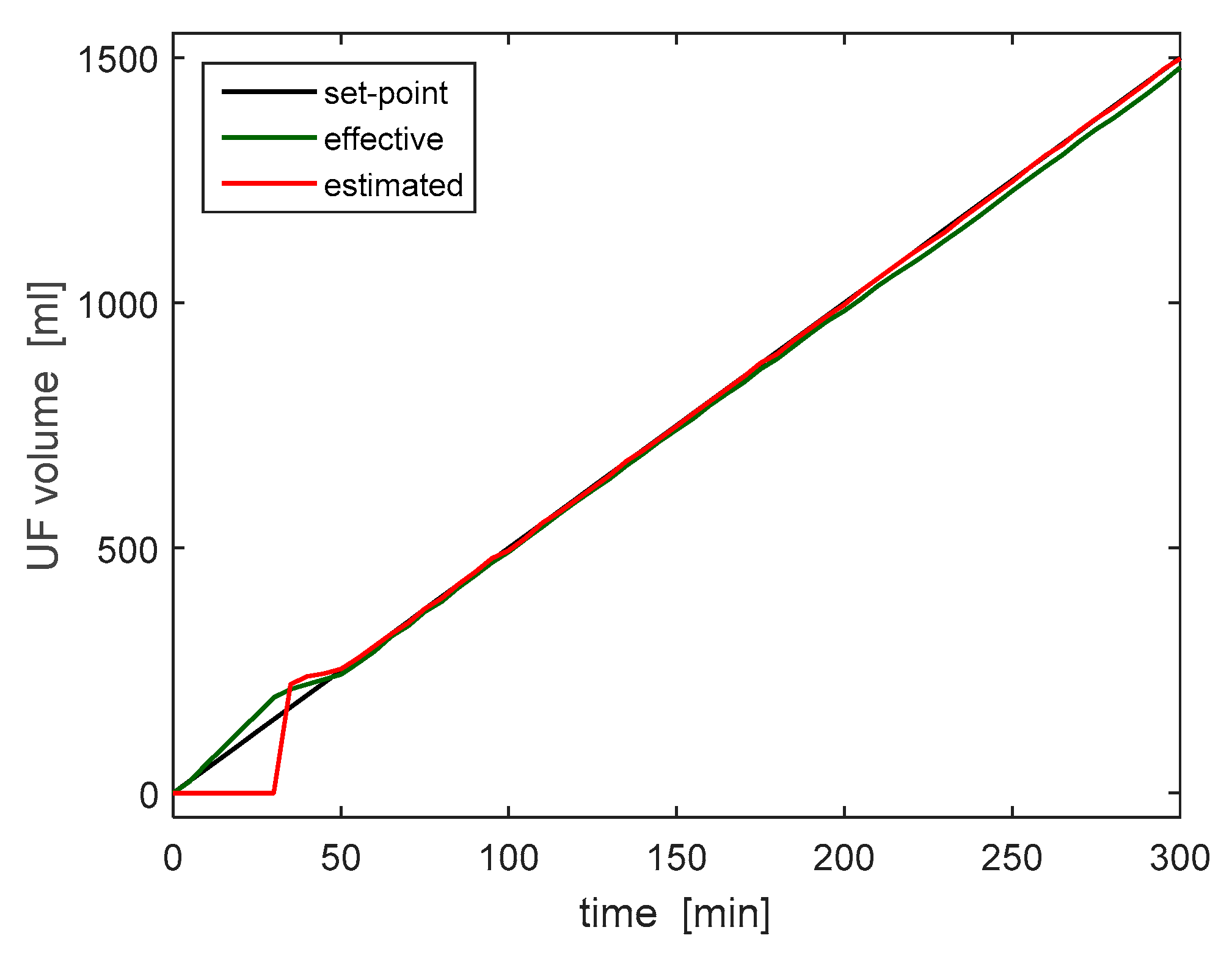
After more than 5 h of continuous operation, no safety hazards were detected, providing a first proof of the reliability of the device. During the same test, the estimation of the ultrafiltration volume has been checked against the reading of an electronic scale. The ultrafiltrate estimation system performs a state estimation by comparing data generated by ultrasonic sensors and accelerometers. No further details are provided here, for patentability issues.
Figure 12 shows the measurement collected during the 5-h trial; the plot compares the UF volume set point (equal to 5 mL/min), to the estimated and measured volumes. With the exception of a short initial interval, when it was not possible to estimate the extracted volume due to the design of the UF tank, the liquid removal rate was estimated correctly and follows the desired one with a minimum error. This test therefore validated both the reading and the regulation of the ultrafiltrate removal rate.
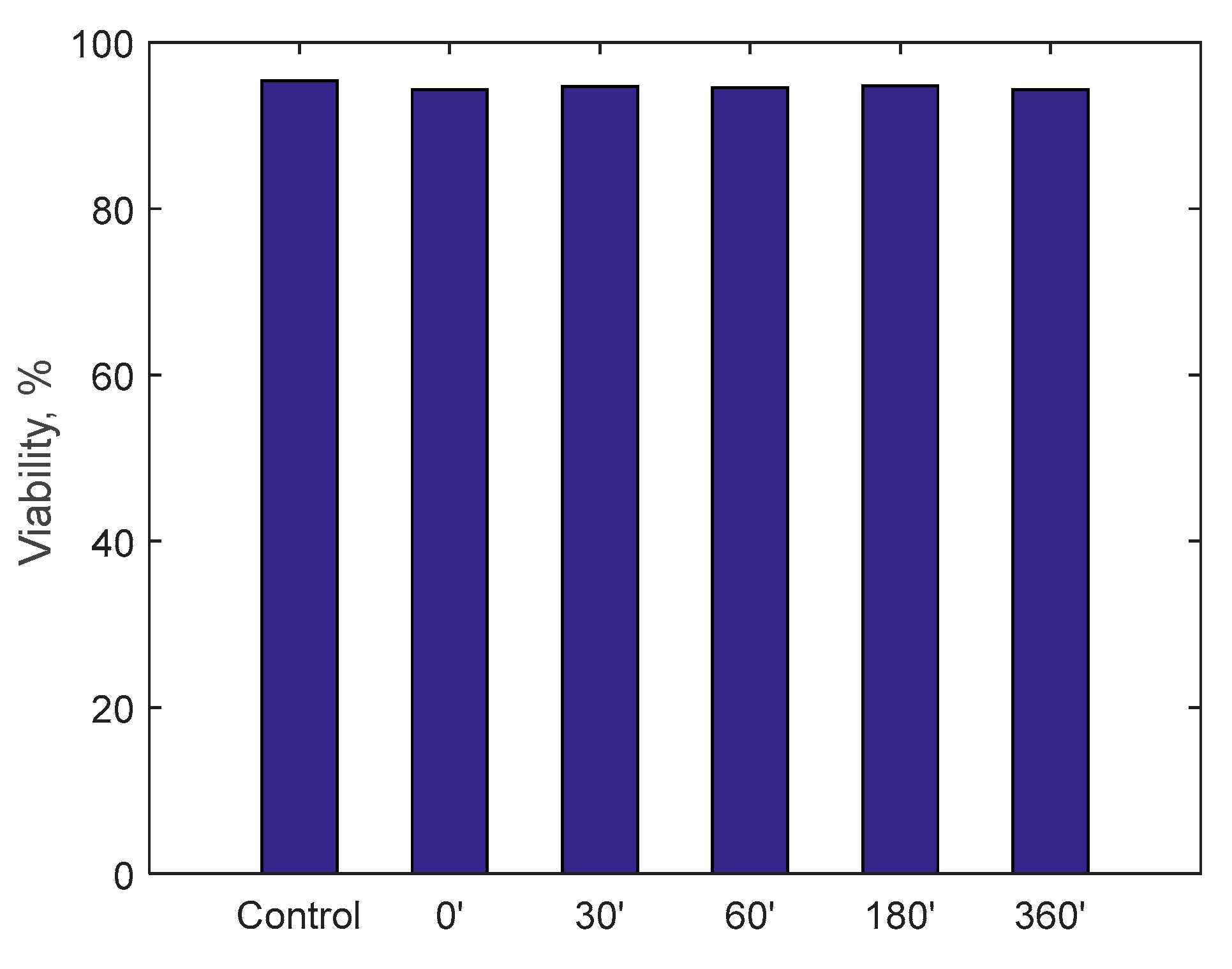
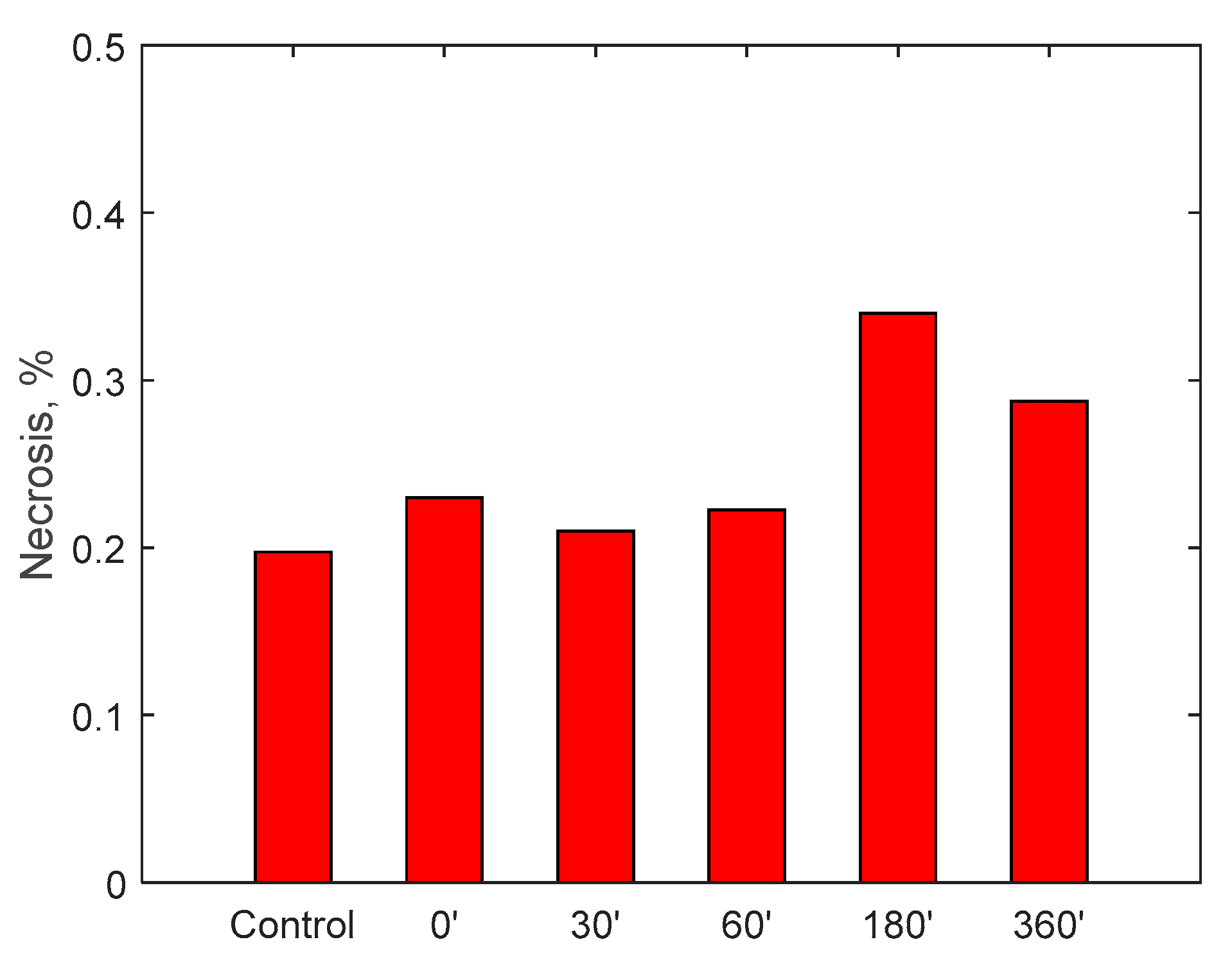
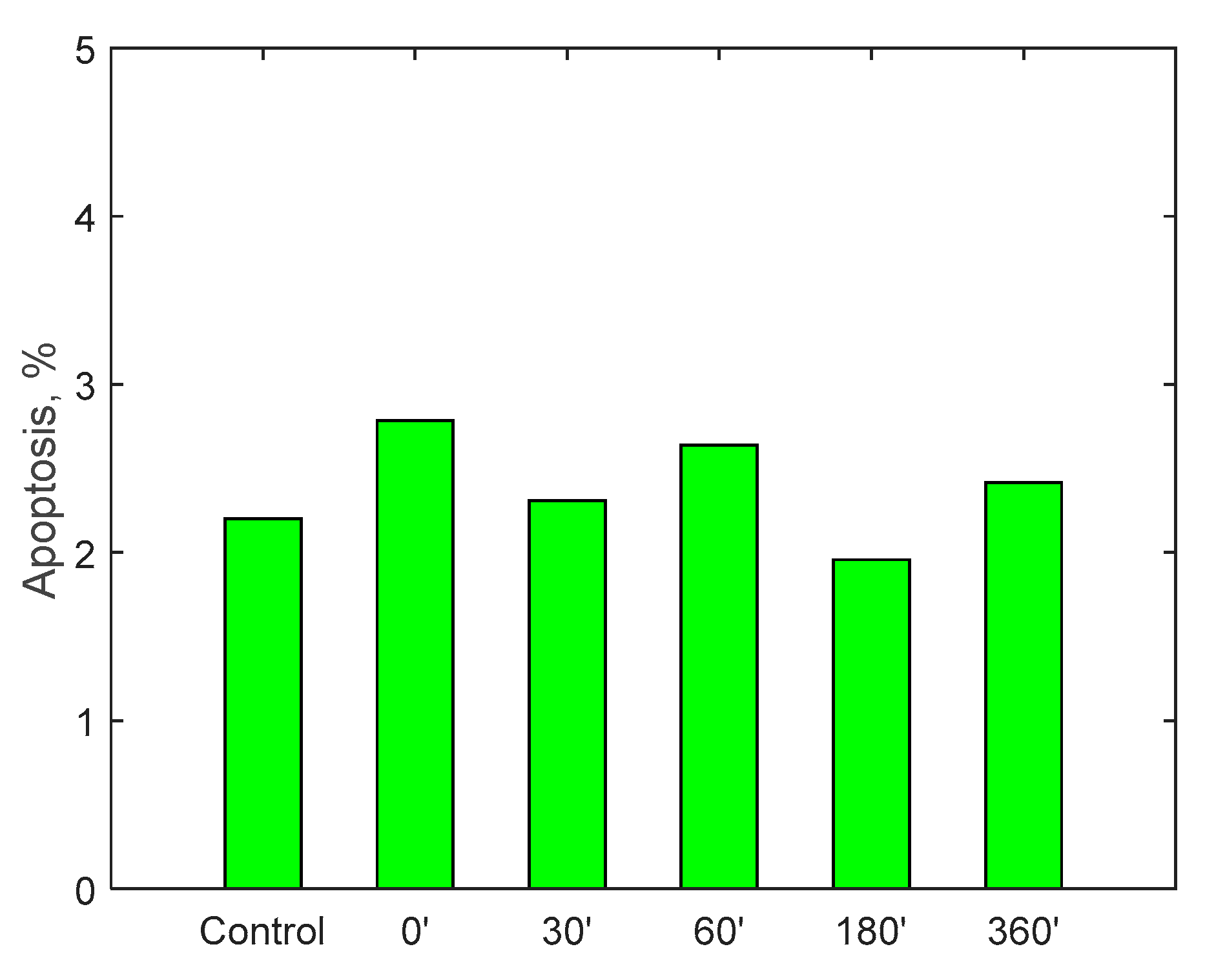
Finally, the possible induction of cytotoxicity has been evaluated, to verify that the device does not lead to excessive deterioration of the blood tissues. The test was carried out by circulating 500 mL of cell medium for 6 h: it is a special-purpose fluid with density and viscosity very similar to water and containing many products necessary for cell growth and maintenance of the physical-chemical conditions such as pH and osmolarity. Cell viability was assessed by measuring the number of viable cells and determined by trypan blue (Sigma, St. Louis, Mo., USA). Fluid samples were collected at the beginning of the test and then after 30, 60, 180 and 360 min.
A specific cell line, monocyte line U937, which is considered to be the gold standard for cytotoxicity analyses, was incubated for 24 h in the samples taken. At the end of the 24 h, via a cytofluorometer, values of viability, necrosis (cell death due to artificial causes) and apoptosis (cell death due to natural causes) of the incubated monocytes were evaluated. These values were compared with a control sample. The analysis of the samples was translated into percentage of viability, necrosis and apoptosis, as displayed in
Figure 13,
Figure 14 and
Figure 15. Data show, for all three parameters, similar values with respect to the control samples within 6-h running time of the procedure, highlighting minimal cytotoxicity. These results confirm the absence of adverse reactions, potentially due to high mechanical stress, increased temperature, release of contaminants or reaction products as a consequence of the contact with external materials and components of the RAP prototype.
6. Conclusions
This work has introduced the first pre-clinical prototype of a novel wearable/portable device for blood ultrafiltration, named RAP. The design mixes additive manufacturing technologies, off-the-shelves components (pumps, actuators, membranes, sensors, electronic devices), and some custom design components, such as a novel electromechanical clamp and a sensorized ultrafiltrate tank. Another significant novelty of the RAP device lies in its layout paradigm, based on three main layers, arranged to fulfill the space occupation specifications defined at the earliest stages of the development. The final design achieved the best tradeoff between miniaturization and ergonomics through a box-shaped design that easily fits a trolley case or a backpack.
The box-like shape is the consequence of stacking three layers of components, one for the disposable devices, one for the non-disposable components and one for the main electronic boards. This arrangement significantly simplifies the maintenance of the device, as well as the procedures that precede and follow each treatment run, achieving the minimization of the time required to complete the operations performed by the trained personnel, which should take care of the initial and final phases of the therapy.
The control architecture has been outlined in detail, highlighting the hardware and software solutions chosen to ensure safe operation of the device.
The functionality of the device has been tested by specific in-vitro tests, through which the correct operation of the critical elements of the design was assessed. The correct and reliable operation of the RAP is complemented by the low rate of hemolysis and the negligible levels of cytotoxicity displayed by the specific test reported here.
The device is now ready for further in-vitro testing, and for in-vivo testing. The device introduced here is the first working prototype, conceived to validate a new design; there is room for miniaturization by deepening integration though a custom electronic design and through the new design of disposable components, such as filters and pressure sensors.

 ,
, 


