1. Introduction
The history of water mills matches the development of prime movers. In general, the aim is to make more energy available for a community, in particular more concentrated in space and time. In fact, the development of a new engine allows an increase in the level of production of a society.
Singer et al. [
1] have identified different stages in the evolution of the prime movers. In the history of humanity, the first traditional available energy has been the human one. Using muscles over motor, the human body can express a continuous power close to 100 W, that could be used for limited production activity [
2,
3]. A first improvement, in terms of total available energy and concentrated power, was obtained using animals as a power source. An animal can continuously develop a power of about 1 W per kilogram, so that a medium ox expresses a power of approximately 500 W, five times that generated by a single man. The second substantial step in the progress of prime movers was, precisely, the development of water wheels. To understand the impact of this innovation, one must consider that, at the end of the Roman Empire, water wheels were able to develop about 45 kW of power, more than four hundred and fifty people [
1].
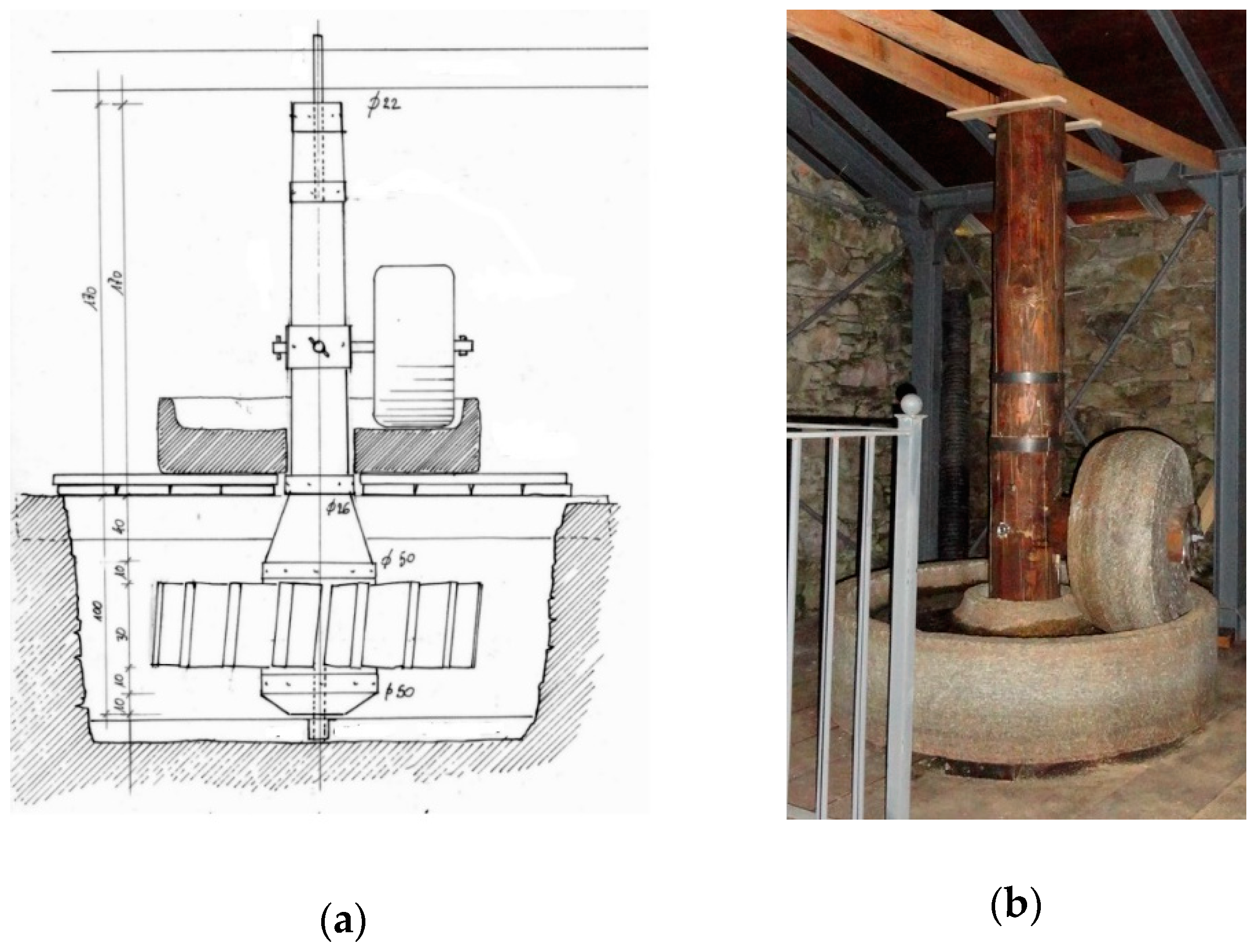
There are two main types of mills: The Greek or Norse and the Vitruvian. The Greek mill originated probably in the mountainous areas of the Near East. The first traces are narrated by Strabo that, in 65 B.C., tells us about a mill built by Mithridates, the king of Pontus, near his palace in Cabeira. This kind of mill has spread both to the east and to the west, and in the fourth century is present throughout Europe. It presents a very simple mechanical architecture: The horizontal wheel is directly coupled to the load through a vertical shaft, supported by an axial bearing cooled by the water flow. The horizontal water wheel is appropriate for the low flow rate and high water velocity, typical of mountain rivers. The mean rotational velocity is about 15–20 rpm. The conversion into mechanical energy occurs with low efficiency. The horizontal water wheel was normally used as the prime mover of small grain mills, suitable for a modest production of flour of the order of a few quintals a day, typical of highland family farming. In some cases, it was also used for running hammers of blacksmith’s workshops and hemp mills [
4], devoted to roll the hemp fibers in order to break down their natural coating and make it pliable enough for spinning and weaving (
Figure 1).
The other kind of mill is the Roman Vitruvian, characterized by a more efficient vertical water wheel keyed to a horizontal shaft. As the power take off often requires a vertical shaft, a more complex power transmission, able to change the direction of the axis of the shafts and, if necessary, to multiply its velocity, is required. The problem was solved with the invention of crown and lantern gears, which, in spite of the augmented complexity, allowed to increase significantly the overall efficiency and productivity of the mill [
1].
Initially, in the Roman Era, the spread of the mills has been very slow, both due to the availability of cheap labor, and to the difficulty in regulating the regime of the rivers of the Mediterranean area, characterized by strong seasonal fluctuations in flow. In fact, all the oldest mills found in archaeological excavations, Venafro, Barbegal, Tournus, Rome and Athens, were fed by an aqueduct. In the Middle Ages, decreasing the availability of workforce, water mills spread considerably, so that in the nineteenth century there were more than 60,000 wheels in France, 30,000 in England and 33,500 in Germany. Water wheels were employed mainly for grain milling, but also for running forge hammers, bellows, mortars, fullers, and saws [
5,
6]. In all civilizations of the past, water wheels (noria) were also used to elevate water [
7]. The peak of the scientific improvement in water wheels design is probably the introduction, in the middle of the nineteenth century, of the Sagebien and Zuppinger water wheels. They replaced the previous models with a considerable efficiency improvement. In the same period, we also see a flowering of scientific works, mostly experimental or concerning design suggestions [
8].
The water wheels use and interest declined only with the construction of big hydroelectric plants and the advent of modern turbines (Francis, Pelton and Kaplan). In the first decades of the twentieth century, dozens of dams were built: The power produced by water wheels cannot compete with the megawatt produced by such power plants.
Today, the numerous old mills, although for the most part disused, represent a huge and precious heritage, which, beyond its historical and cultural value, has a remarkable potential. Old water mills, in fact, could be restored both for the direct actuation of machines, in the case of museum exhibitions or small high quality local productions (millstones, blacksmith’s hammers, etc.), and for the conversion into mini-plants for the production of electricity.
On the other hand, water wheels and old mills have significant advantages:
- (i)
they do not require the construction of new masonry, or water derivation channels;
- (ii)
they already have a water use concession, often still ongoing;
- (iii)
they are perfectly integrated into the environment;
- (iv)
they are welcomed by the local population, being perceived as not impacting, beautiful, related to memory;
- (v)
they are often widespread in isolated and underserved internal areas, such as small mountain villages;
- (vi)
they use renewable energy.
Precisely because of the historical value of the water mills, Rojas-Sola et al. [
9] modeled a mill using SolidWorks CAD, and generated a computer animation of the production process as a subject of a course in the history of technology.
Rojas-Sola et al. in addition studied, from a hydraulic and mechanical point of view, typical Spanish watermills, with horizontal water wheels. The aim of the work was graphically modeling the mill, in order to understand its dimension and to be able to make a virtual recreation of its functioning, and secondly to obtain the principal technical parameters, such as the supply flow rate and the power of the water wheel [
10,
11].
Pujol et al. conducted a detailed analysis of the performance of ancient Spanish horizontal water wheels [
12] and the study of the implications of several technological innovations applied to the old classical horizontal waterwheels implemented in Gaserans (North-East Spain) [
13].
The present work aims to describe the mechanical architecture of typical Piedmont (Italy) Vitruvian mills, and to analyze in detail the functioning of the water wheel, the mechanical power transmission and the regulation mechanisms. First, the research was carried out for a historical interest, but also in the perspective of recovering the original use of old mills, or for their reconversion into micro hydropower generators for electricity production. The economic sustainability of a restructuring operation of an old mill depends in fact on the state of preservation of the site, on the type of water wheel installed, on the condition of the mechanical transmissions, and, in summary, on the overall efficiency of the whole machine, from the wheel to the load.
The paper is organized as labeled below. First, different types of vertical water wheels are described. Then, the power transmission, between the wheel and the millstones, is analyzed from a functional point of view. Thereafter, the regulation systems and the mechanisms of the mill are presented. Concluding, the usefulness of the development of a device devoted to the experimental characterization of the efficiency of the mill transmission, from the water wheel to the load, is discussed.
For this purpose, two old mills, the Riviera mill and the Forno mill, are analyzed in detail.
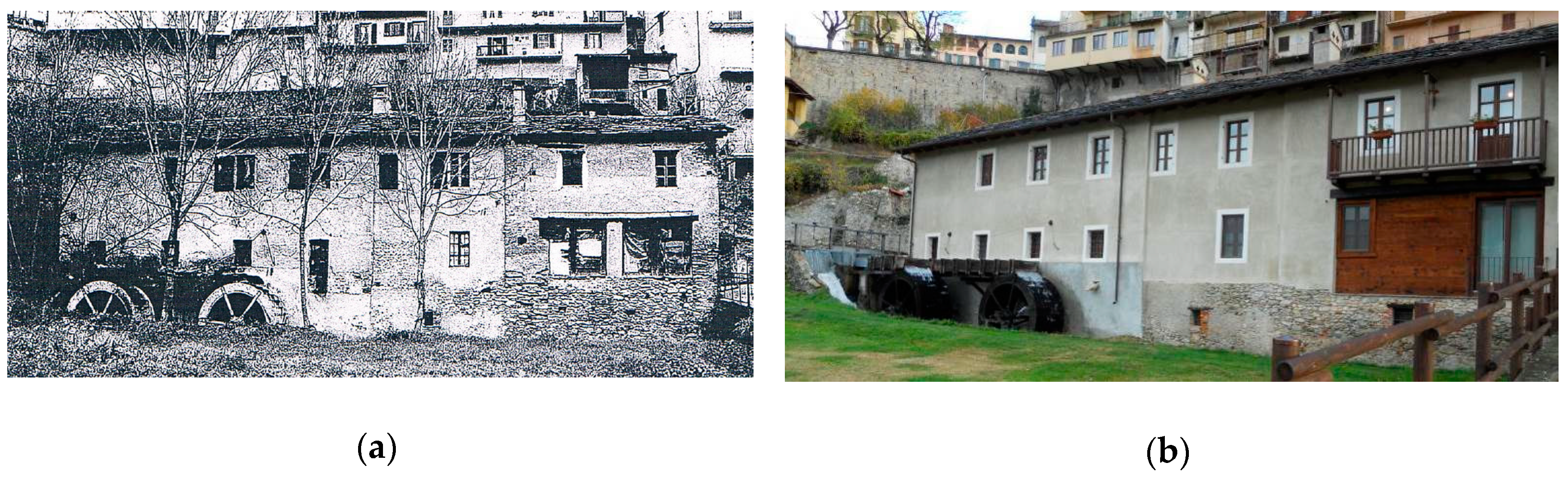
The Riviera mill is a virtuous example of the restoration and reactivation of a grain mill for small productions of high quality organic flours in the short food supply chain [
14]. The Riviera mill (
Figure 2) is located in Dronero (North-West of Italy—44°28′ N and 7°21′ E) and dated back to the XV century [
4,
15]. It was renewed and extended several times [
4]. In 1811, a first building extension request was made to realize a sawmill and add a water wheel. In 1813, it is attested that the mill has three millstones. In 1819, the addition of a new wheel is authorized. The main extension is carried out in 1859, as evidenced by an inscription on the entrance porch. In 1919 the mill, equipped with three millstones, is able to produce 10 quintals of flour per day. The mill was used for grinding wheat and maize corn until the 1970s, when it was abandoned. In 2002, the Cavanna family bought and renovated the Riviera mill, and re-started the milling of flours with natural stones.
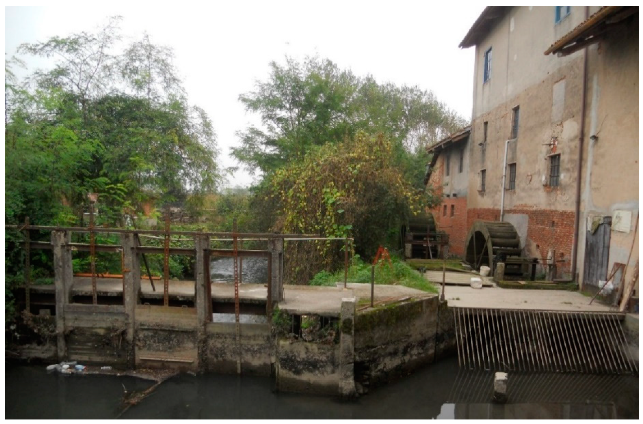
The Forno family is the owner of a mill that produced flour, corn by-products and animal feed until 2011. The Forno mill (
Figure 3) is located in Verolengo, in the Metropolitan City of Turin (North-West of Italy—45°11′ N and 7°58′ E). From a deep documentary analysis, it is possible to set the mill’s building between 1874 and 1878 and, presumably, it was built on the ruins of an older abusive mill. The first presence of the Forno mill is reported in a military map dated 1882. From a more recent note, dated 1933, it is possible to deduce the start of the activities in 1879 and the characteristics of the permit to derive water from the “Roggia dei Mulini”. In 1946, the productive apparatus were enlarged and the original millstones replaced. The production definitely stopped in 2011. The mill is actually under consideration for a possible inclusion in a proposal for an ecomuseum.
2. The Water Wheels
Gravity water wheels (GWWs) are members of the group of machines that are used to convert hydro energy into mechanical energy. In general, we can categorize them according to the exploited energy transformation. Action turbines exploit the flow momentum (i.e., kinetic energy), reaction turbines convert both the flow momentum and the water pressure (they are installed in closed pipes) and hydrostatic pressure converters (HPCs) exploit water hydrostatic force. In a HPC, the hydrostatic force is generated by the water weight contained inside the machine buckets. The stream and vertical axis water wheels, Pelton, Turgo and Cross Flow turbines belong to the first group. In the second group the Kaplan and Francis turbines are present, while the last group includes gravity water wheels (GWWs) and Archimedes screws. GWWs rotate around a horizontal axis while in an Archimedes screw, the axle is inclined on the horizontal of about 22° to 35°.
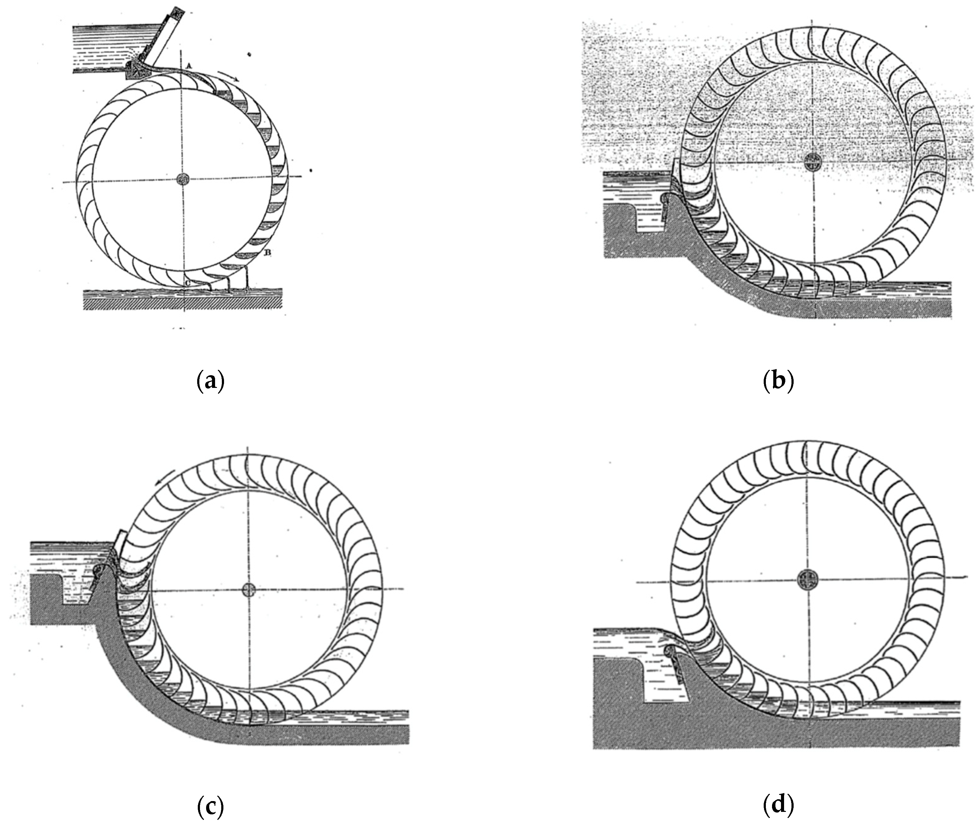
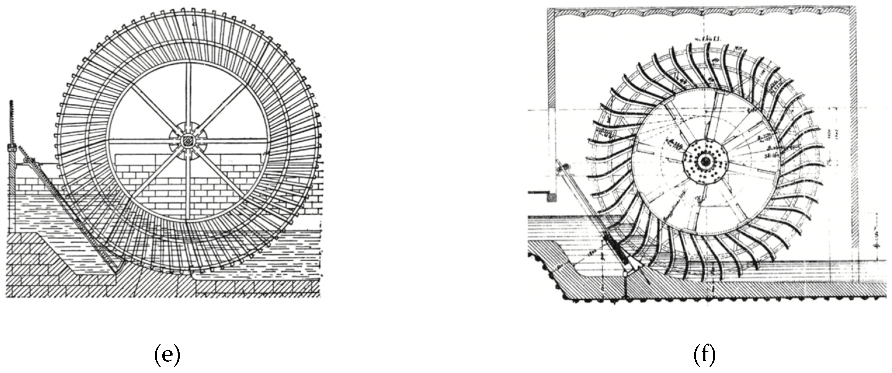
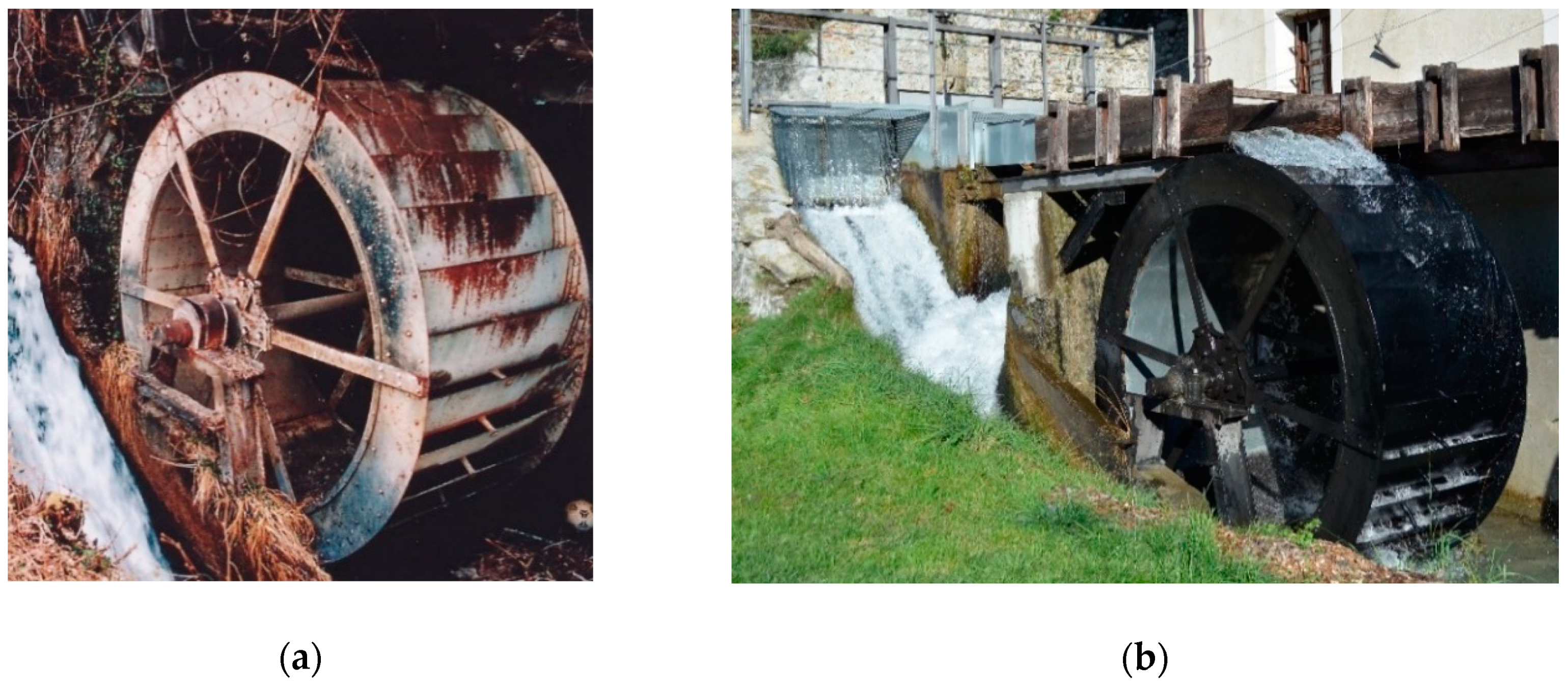
Gravity water wheels are generally divided in several types, depending on the water entry point (
Figure 4). In an overshot GWW, the water enters from the top. In breastshot WWs, the water enters from the upstream side and, depending on the water level position with respect to the rotational axis they can also be divided in high, middle and low breastshot GWWs. The low breastshot WW is often classified as an undershot GWW. The overshot GWWs (
Figure 4a) rotate in a clockwise direction, on the opposite breastshot and undershot GWWs rotate in a counterclockwise direction (
Figure 4b–d). Sagebien and Zuppinger GWWs differ, in particular, for the blades geometry: Sagebien and Zuppinger GWWs the curved blades optimize the inflow and outflow power losses, respectively.
Operatively (
Table 1), WWs have a maximum efficiency between 70% and 90%. The typical exploitable head is 1–6 m, flow rate lower than 1 m
3/s and power less than 50 kW. The Riviera mill and the Forno mill consist of overshot and breastshot GWWs, respectively, with horizontal rotating axles.
The water wheel shaft is normally supported by two plain bearing, lubricated by grease or oil, mounted across the canal on a metal frame (
Figure 5b) or a brick structure (
Figure 6b).
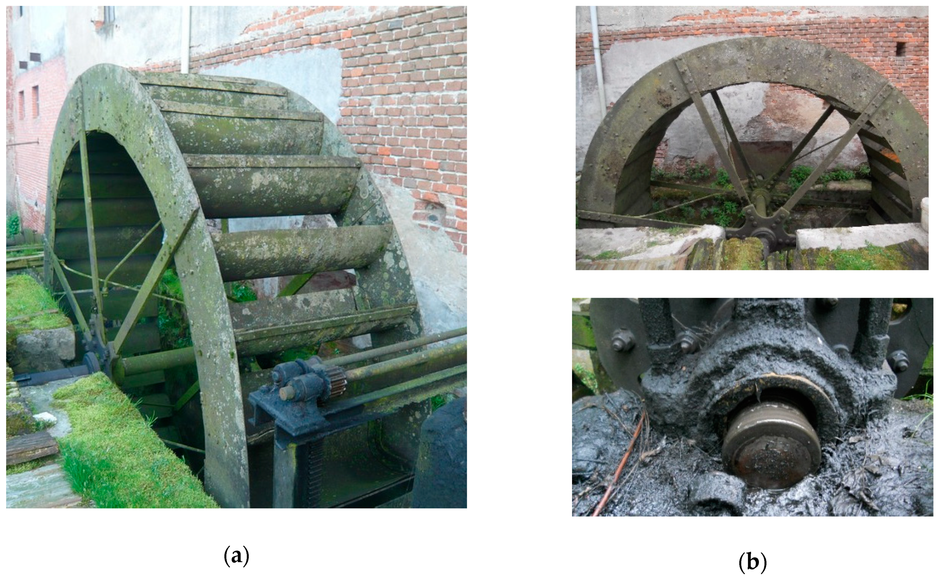
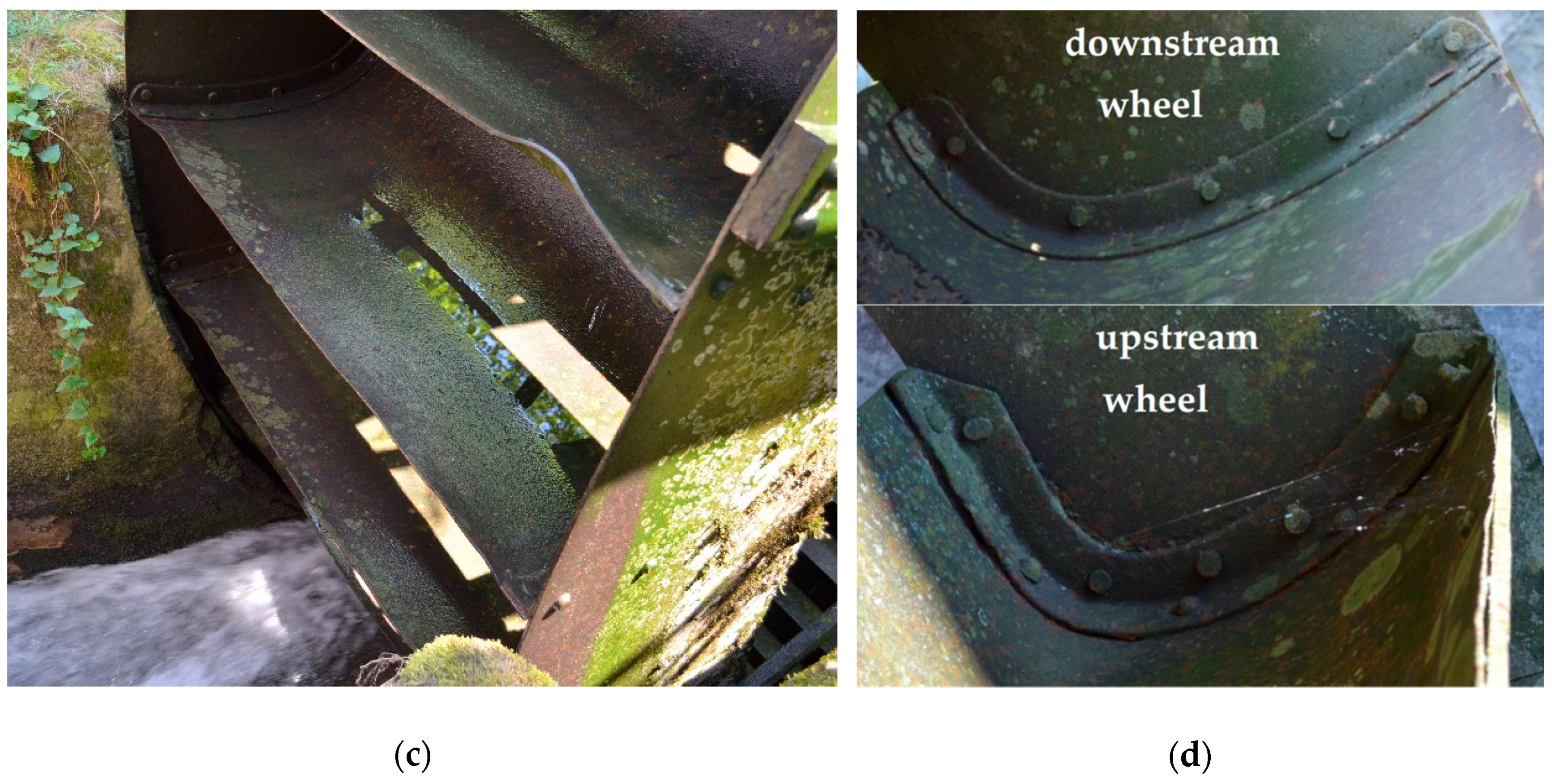
The Riviera mill consists of two metallic WWs (
Figure 2 and
Figure 5) and the water is supplied by the Maira River through the Bealera Comella. The wheels are 1.3 m wide and have a diameter of 3.0 m. They are an overshot type with 30 blades and rake angles equal to 60°. The Forno mill uses the water derived from the Dora Baltea River through a complex system of irrigation canals (Roggia Natta, Roggia del Veuchio, Roggia di Neirole). The system dates back to the 15thcentury and allowed to convey the granted flow rate in the Roggia dei Mulini. The two metallic water wheels (
Figure 6) have a diameter of 4.0 m, width of 1.4 m and 32 blades.
A complete analysis of the efficiency, output power and power losses of the Riviera mill and Forno mill WWs has been performed through theoretical analyses, experimental measurements in a laboratory device and with the help of CFD numerical simulations [
20,
21,
22,
23,
24,
25]. The results have been also used for the check of ancient and popular past formulation [
8,
26].
For the sake of simplicity, we report here the main results of the hydraulic study, leaving it to the interested reader to deepen in the cited papers. The efficiency is related to water energy input from the upstream channel, power output and power losses and these latter occur in several parts of the installation
where
is the WW efficiency,
is the mechanical output power and
is the difference between the water power upstream (
) and downstream (
) the WW, respectively. The losses depend on the WW type. In the overshot case (Riviera mill)
where
is the power loss occurring in the impact,
is the possible impact loss generated when the blades impact against the tailrace,
is the mechanical friction loss at the shaft supports,
is the volumetric loss at the top of the wheel and
is the volumetric loss during rotation. Similarly, in the breastshot WW (Forno mill)
where
are the hydraulic losses between the sluice gate and the WW,
is the loss due to water that filters from the slits between the buckets and the channel,
is the drag effect of water on the channel bed and
is the loss that occurs when the residual power of the water in the last bucket is lost in the tailrace. In [
20,
26] the power losses are related to the WW’s geometric characteristics and the channel’s hydraulic characteristics.
The theoretical, experimental and numerical analysis allowed to identify the reference results reported in
Table 2. In particular, the Table shows the wheel efficiency and the relative importance of the power losses with the consequent suggestion for possible efficiency improvements [
25,
27].
3. The Power Transmissions
In a Vitruvian mill, the power transmission devices, included between the water wheel and the load, have a dual purpose: (i) To change the direction of the axis of the shafts, from horizontal and perpendicular to the main wall of the mill, to vertical, for example to rotate the runner stone in the grain mills; (ii) to multiply the angular velocity of the load shaft, in order to increase the productivity.
As an example,
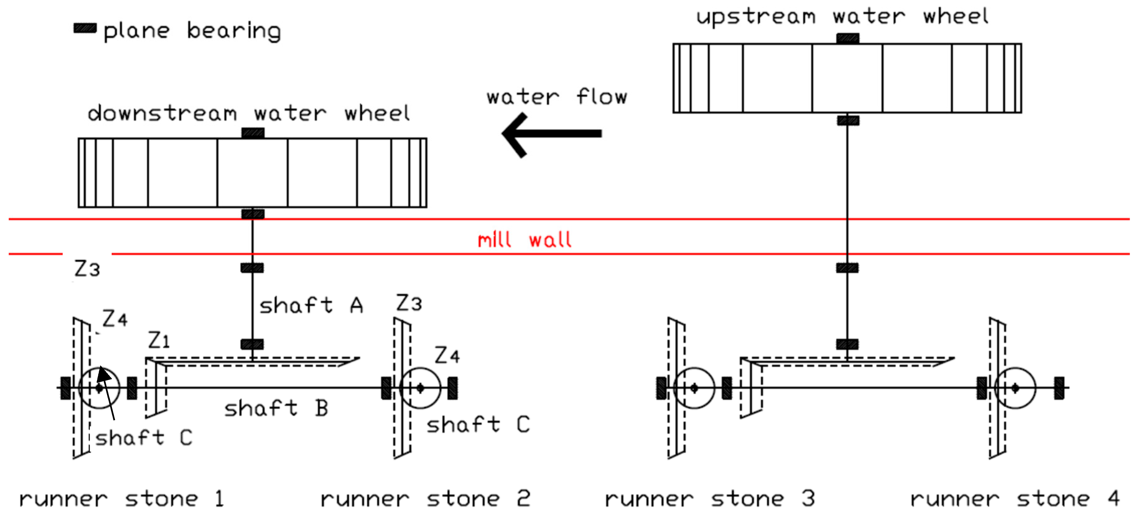
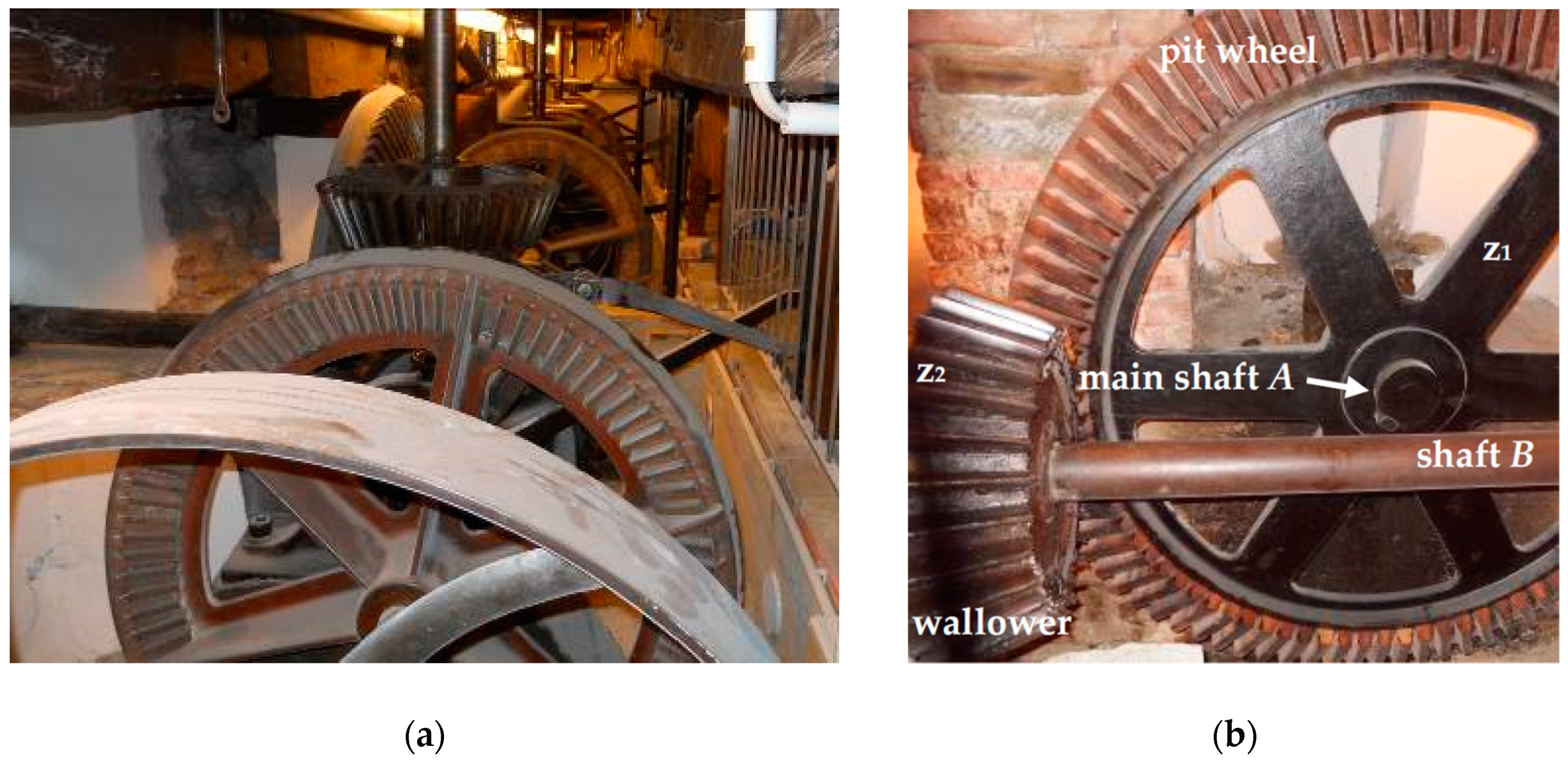
Figure 7 shows the scheme of the Riviera mill power transmission. An overview of the same power transmission is reported in
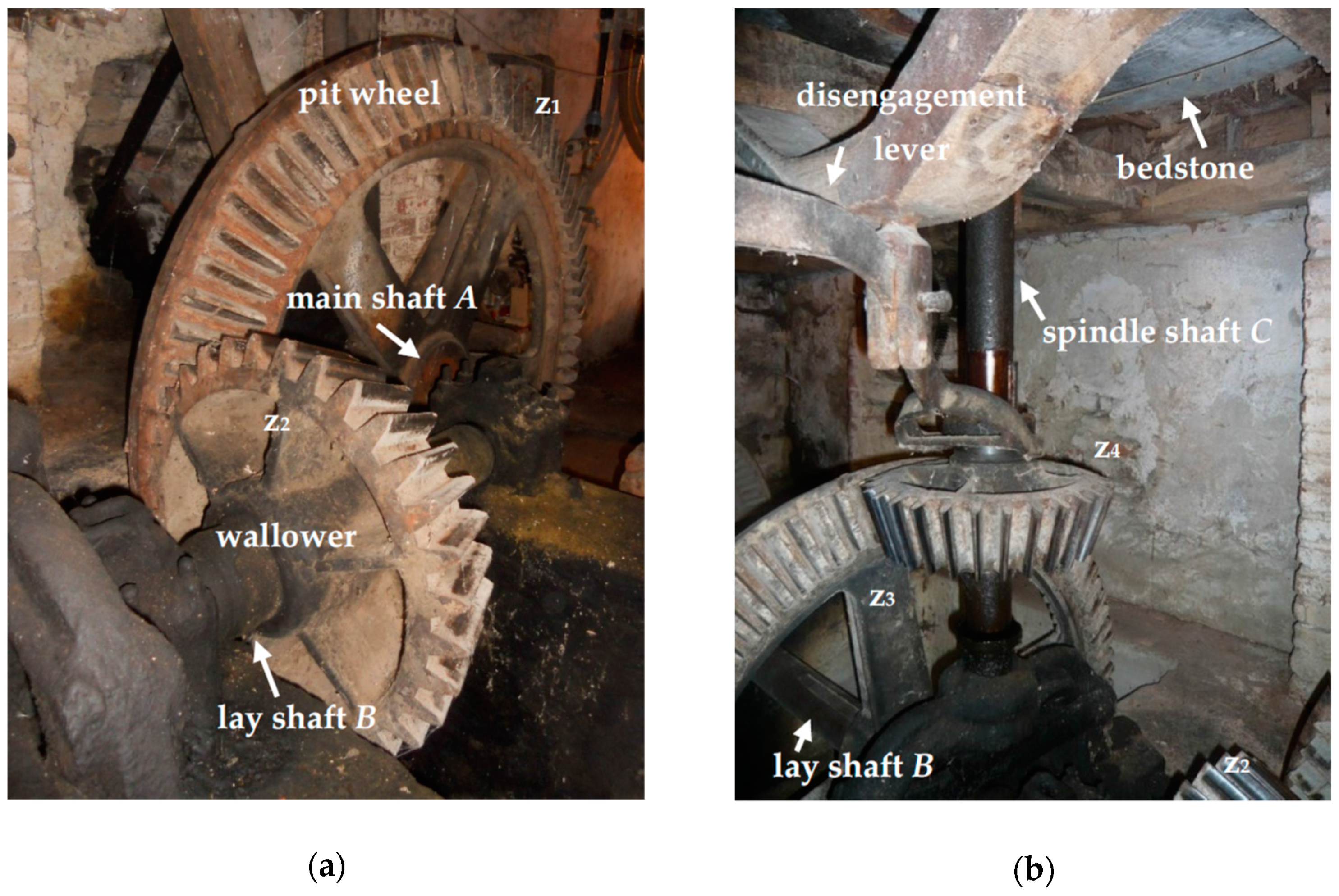
Figure 8a. Each of the two water wheels can be connected to two runner stones through an independent power transmission system, but the single water wheel can drive only one millstone at a time. The two power transmission systems are analogous, therefore only the one operated by the downstream water wheel is described below in detail. The downstream water wheel is keyed to the shaft
A, called the main shaft (
Φ = 120 mm), that crosses the mill wall. A first bevel gear multiplier (
Figure 8b), with teeth number respectively
z1 = 96 and
z2 = 40, drives the shaft
B, said lay shaft, (
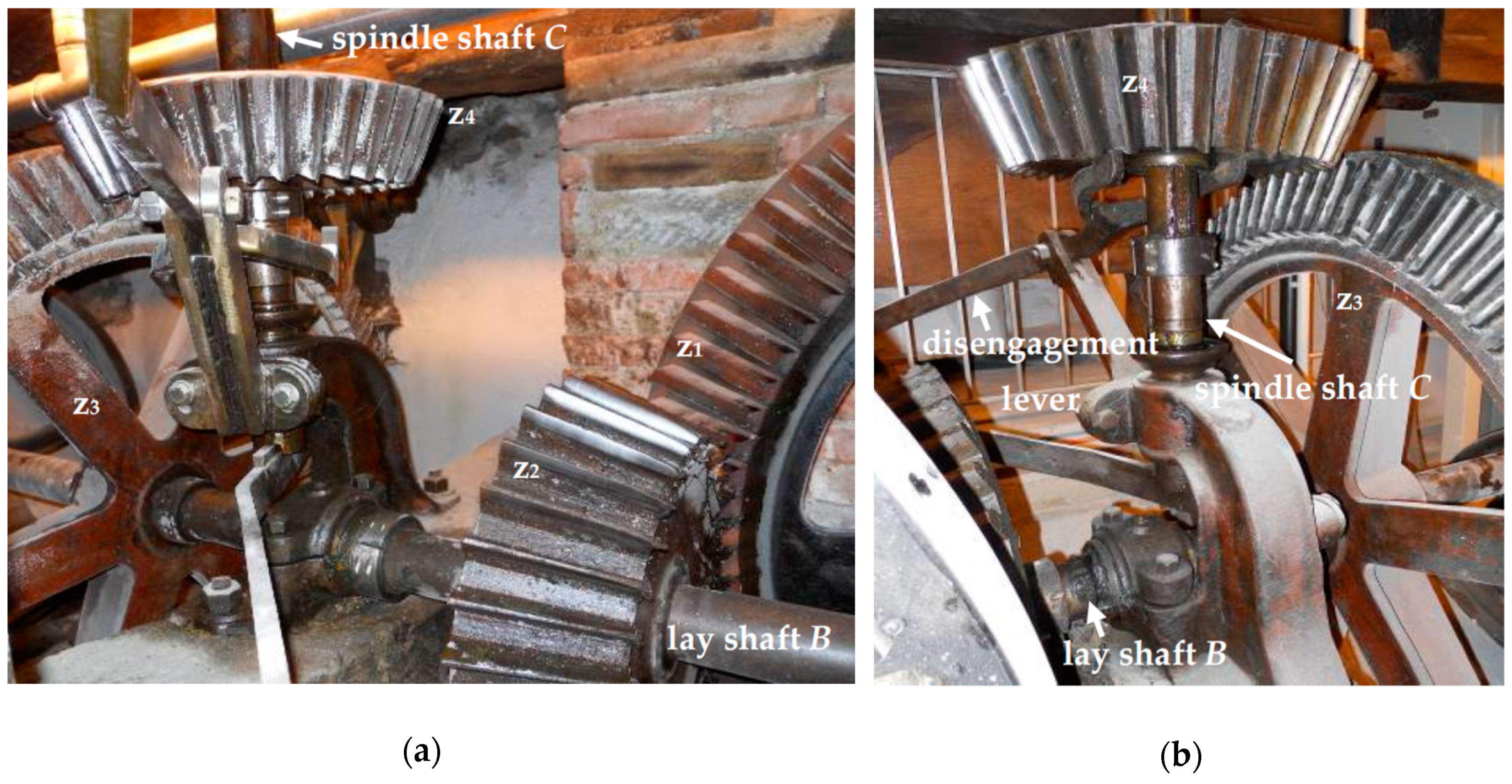
Φ = 78 mm), arranged horizontally in parallel to the perimeter wall of the mill. The first gear of the bevel multiplier, keyed to the water wheel shaft, is called the pit wheel; the second gear is called the wallower. A second bevel gear train (
Figure 9), with teeth number respectively
z3 = 90 and
z4 = 34, further multiplies the rotation speed of the output vertical shaft C, called the spindle shaft (
Φ = 80 mm), that actuates the runner stone one.
The overall gear ratio ωC/ωA is then equal to 6.35, whereby the nominal rotation speed of the millstone ωC is about 60 rpm, while the rotation speed of the water wheel ωA is about 10 rpm.
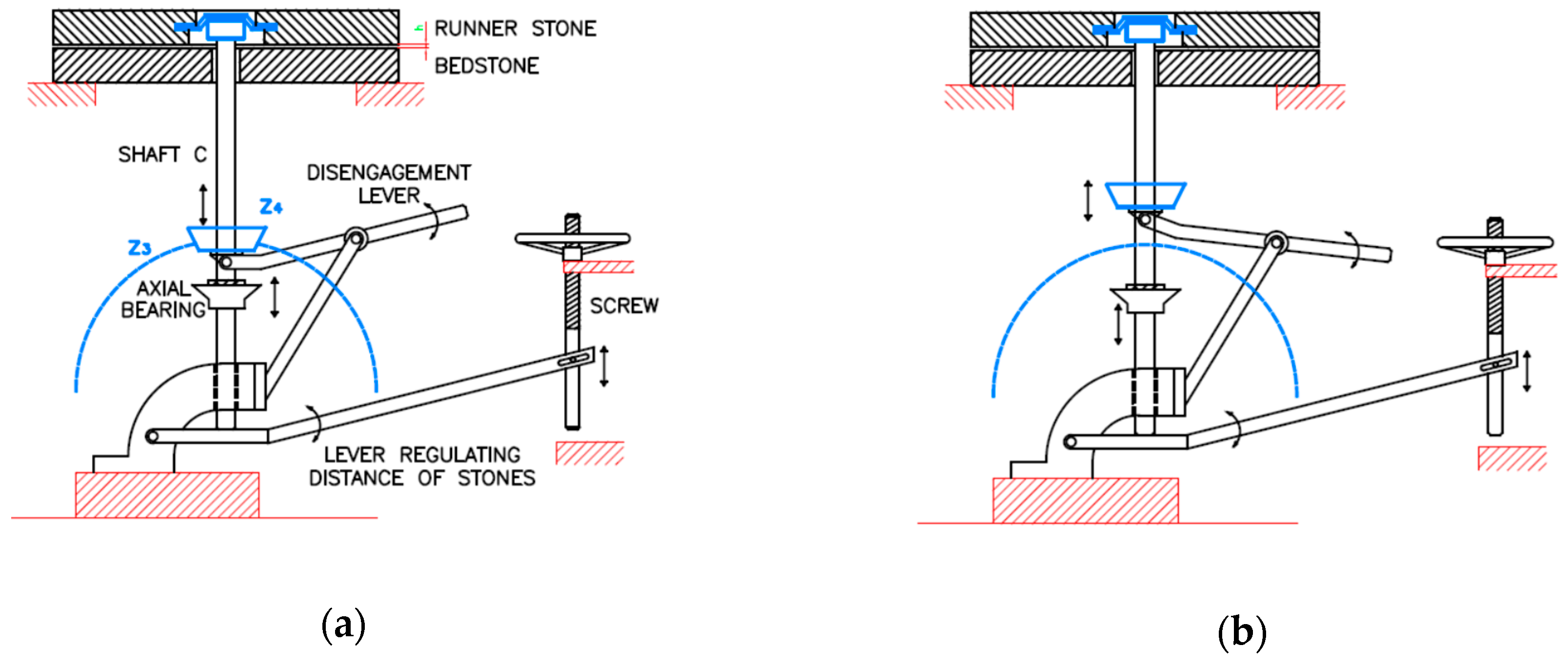
The rotation of the runner stone can be stopped by moving the bevel gear
z4 along the spindle vertical shaft
C through a special lever (
Figure 9b), until the contact between teeth
z3 and
z4 is interrupted.
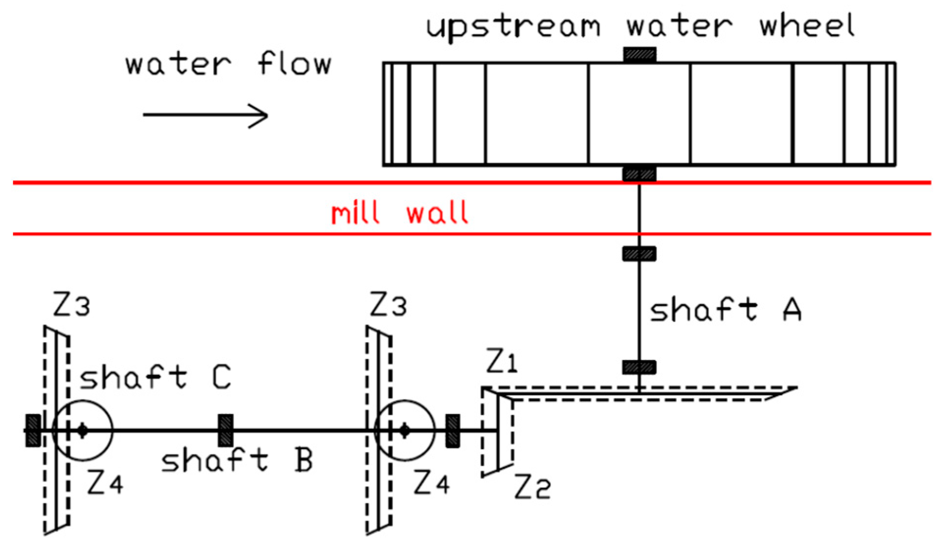
The power transmission architecture described above is common to that of several old grain mills. It is found, for example, in the mechanical transmission of the upstream water wheel of the Forno mill that can drive two running stones as shown in the scheme of
Figure 10.
Here again, the change in the direction of the shafts, and the multiplication of angular velocity of the runner stone are realized by two bevel gears (
Figure 11), whose functional parameters are summarized in
Table 3. The overall gear ratio
ωC/
ωA is equal to 6.57, almost equal to the overall speed ratio of the Riviera mill. The only difference consists in the plan distribution of the transmission, imposed by the conformation of the building. While in fact in the case of the Riviera mill, the wheel
z2 is keyed in the middle of the lay shaft
B, between the two millstones (
Figure 7), in the case of the Forno mill it is positioned at the right end of the lay shaft
B (
Figure 10).
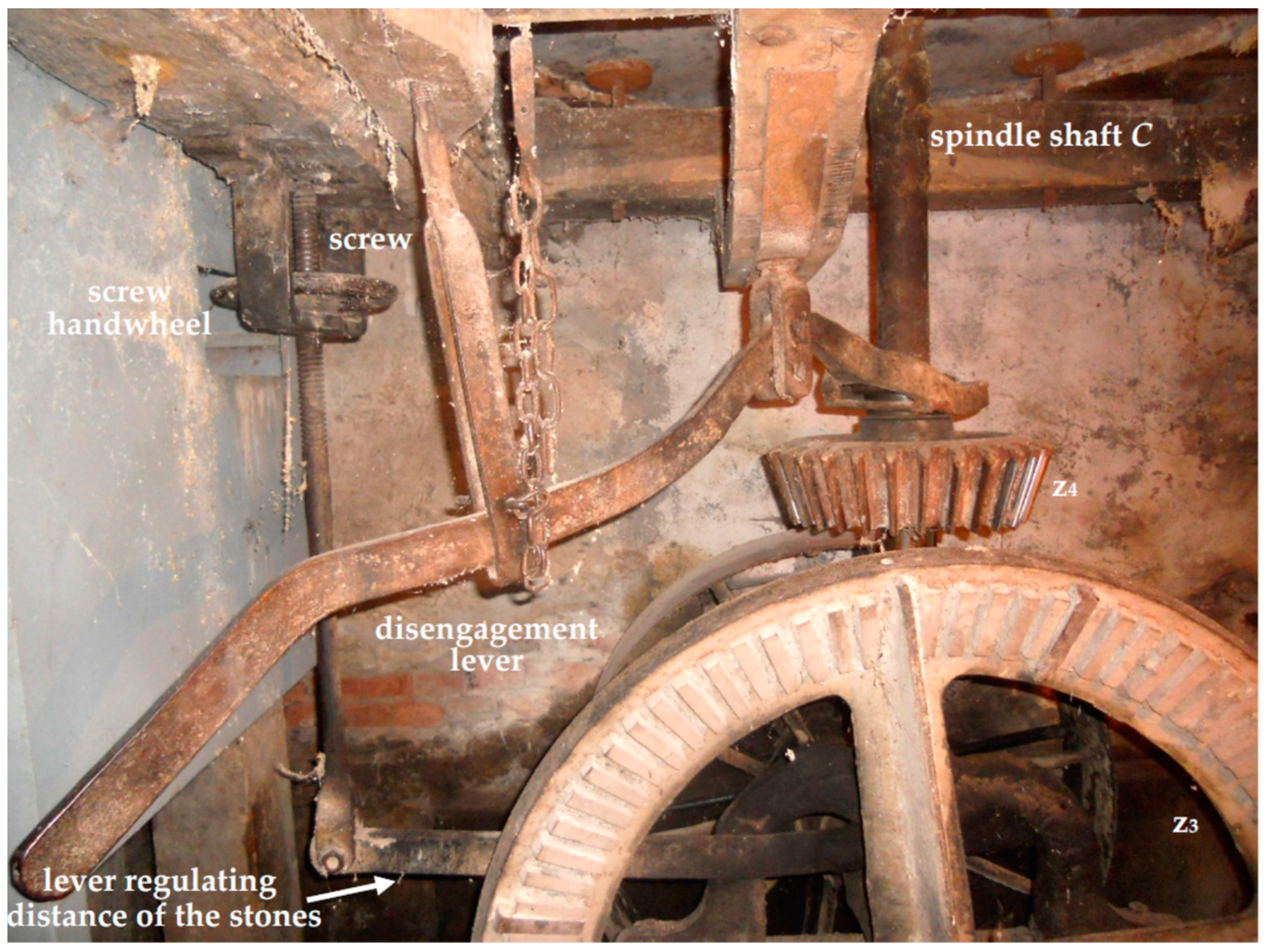
Additionally, in the case of the Forno mill, the actuation of each runner stone can be stopped by operating a special lever, whose function is to move vertically the gear
z4, connected through a key to the spindle shaft C, until the contact between teeth
z3 and
z4 is interrupted (
Figure 11b and
Figure 12). In this case, the disengagement lever is hinged to the wooden beam, which supports the floor on which the millstones are placed (stone floor).
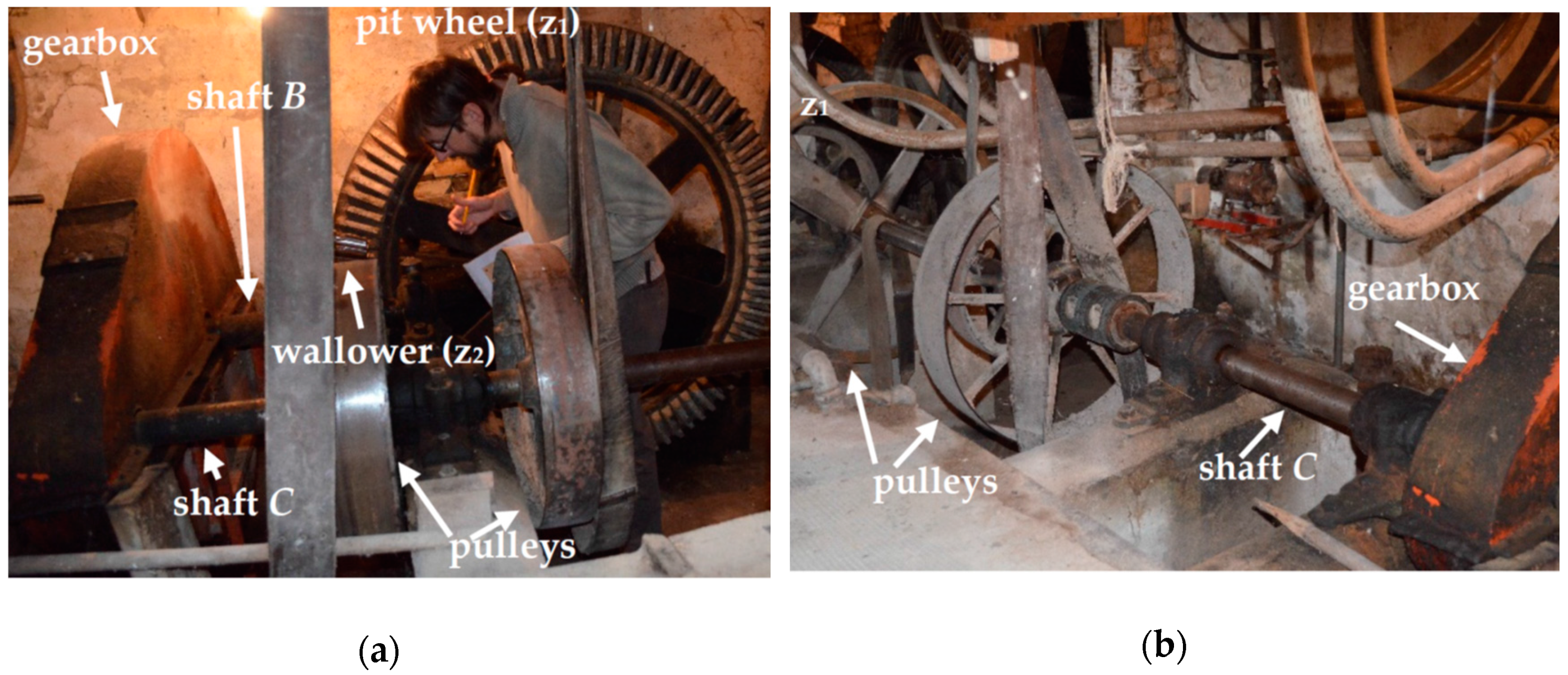
The downstream water wheel of the Forno mill, instead, drives more recent roller mills. After the first speed multiplier (
Figure 13a), consisting of the usual bevel gear pair (see
Table 3:
z1 = 96,
z2 = 31;
z1/
z2 = 3.09) there is a gearbox consisting of a pair of straight teeth spur gears, that transmit the power to a third shaft C, now horizontal and parallel to the main building wall (
Figure 13b). Although it was not possible to open the box of the multiplier, its multiplication ratio was evaluated to be about four, simply by estimating the radius of the two gears. It follows that the overall gear ratio
ωC/
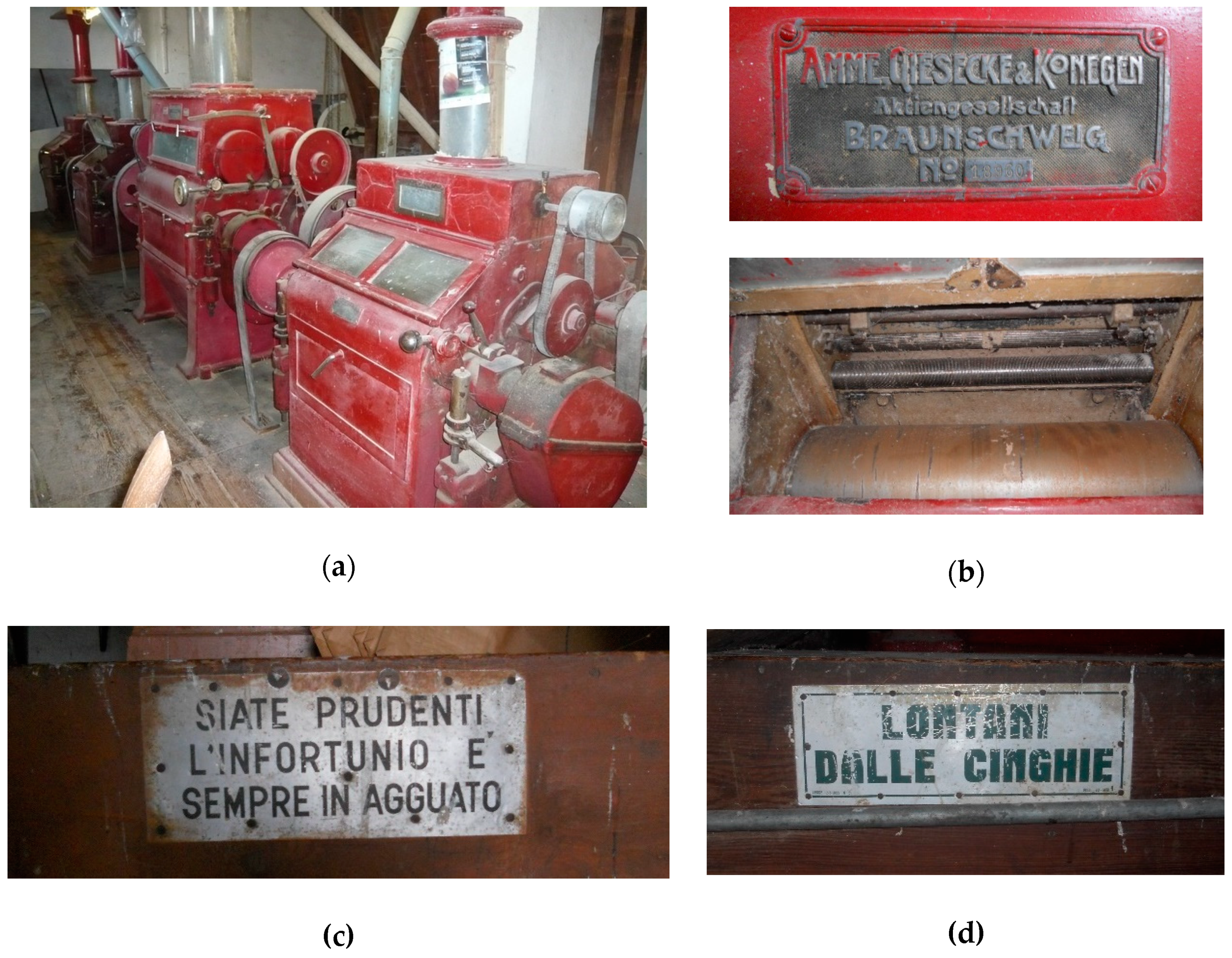
ωA is about 12, almost twice the overall gear ratio of the oldest upstream wheel power transmission. Several pulleys with a diameter of about 550 mm are connected to the shaft
C and transmit, by flat belts, the power to the roller mills of manufacture Amme Giesecke & Konegen, Braunschweig, Germany (
Figure 14). To prevent accidents due to the use of non-protected belt drives, several old injury prevention sign are displayed in the mill (
Figure 14c,d).
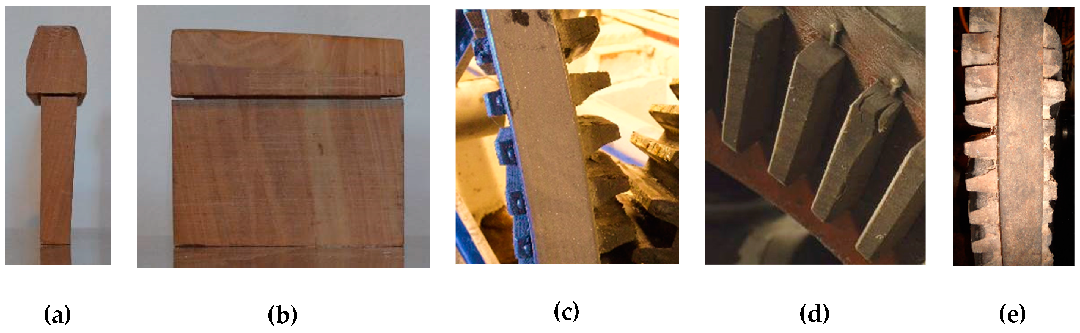
In all the bevel gear pairs, the teeth of the first gear are made of apple wood (
Figure 15). The wooden teeth present the following advantages: (i) They can be easily manually produced with a simple band saw; (ii) they introduce a mechanical compliance in the transmission that absorbs the impulsive loads during the starting and stopping transient states; (iii) they reduce the noise generated by the mechanical transmission; (iv) they are prone to wear preserving the integrity of the metal teeth (
Figure 15c,e); (v) they are easily replaceable once worn, being set in a rim, in which they are driven and keyed (
Figure 15d,e).
On the other hand, both because the teeth do not have the proper shape and for the considerable wood friction coefficient, the efficiency of the mechanical transmission with wooden teeth mortise wheel is certainly low. This must be carefully assessed in the case of reconversion of an ancient mill for the production of electricity, and measured as discussed in conclusions.
4. Regulation Devices
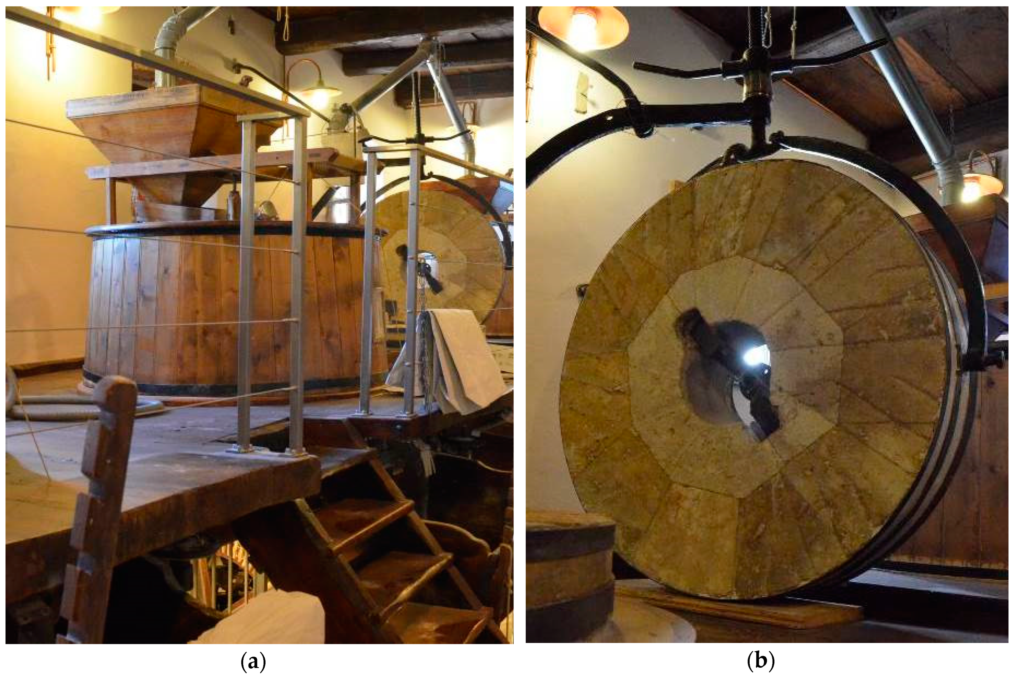
The Riviera mill vertical shaft
C (spindle) supports and moves the runner stone, on the top of the fixed one, called bedstone (
Figure 16).
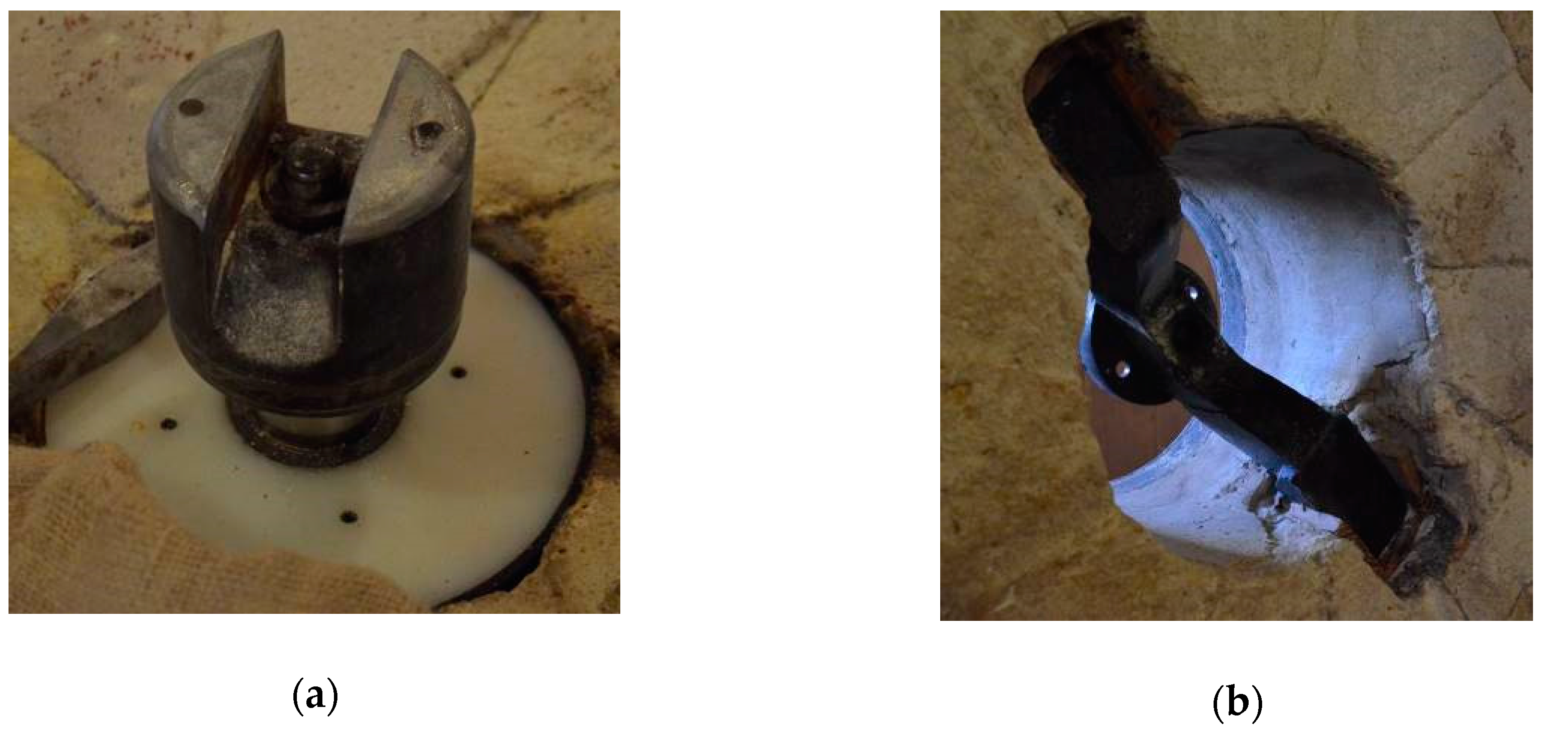
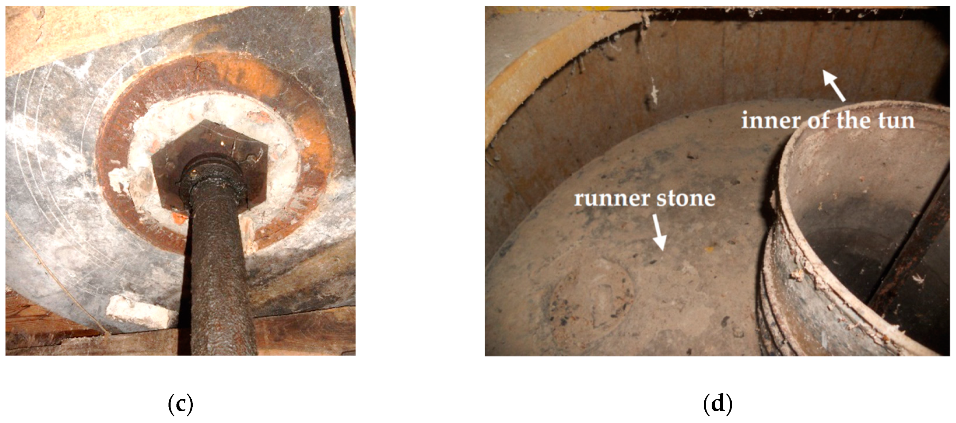
The connection between the shaft C and the runner stone is made with the coupling of the
Figure 17a,b, in which it is also possible to see the radial plain bearing of the shaft C integral with the bedstone, made of Teflon after the renovation of the Riviera mill.
Figure 17c shows, from below, the original same plain bearing used in the Forno mill.
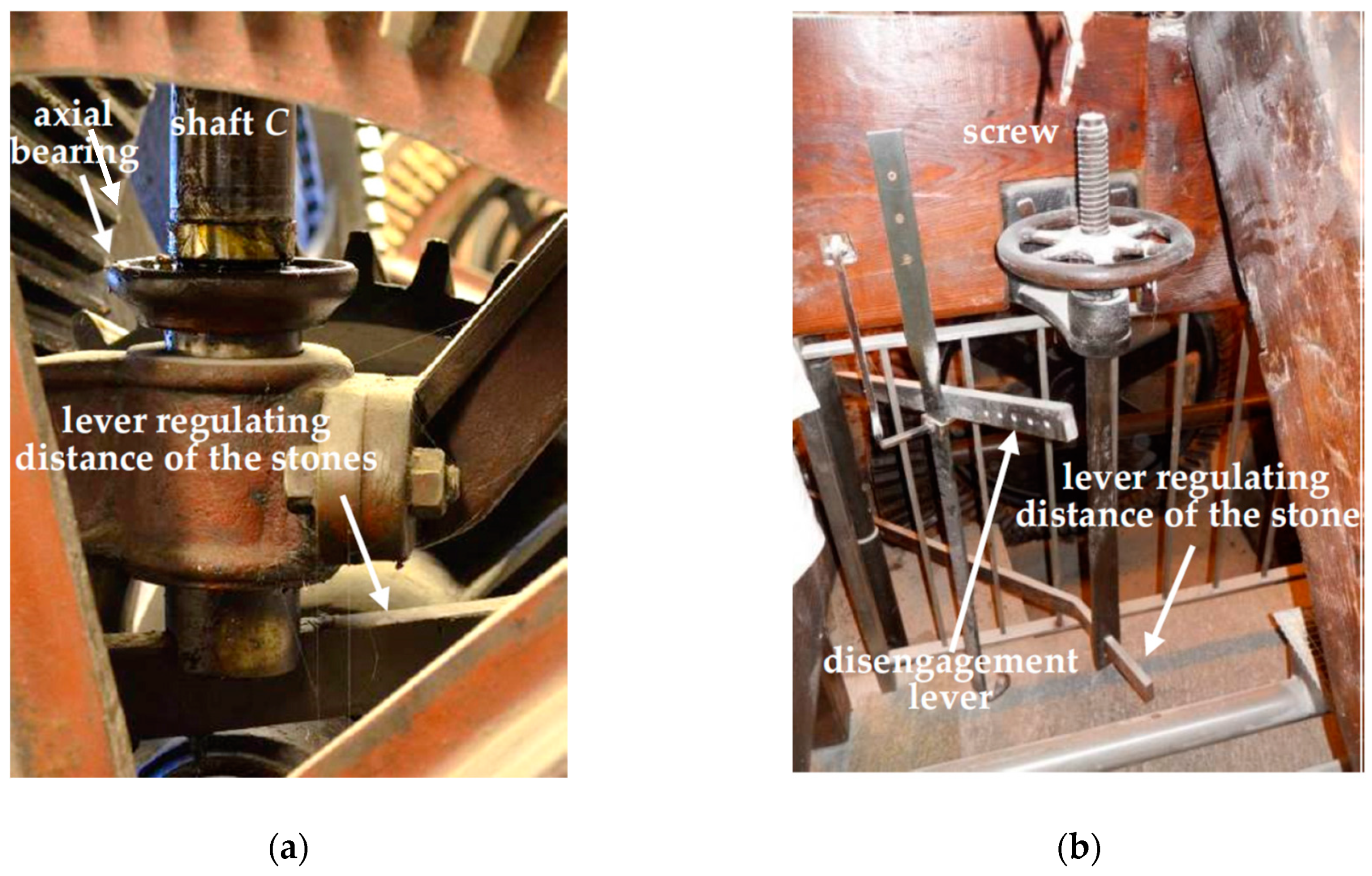
The vertical load of the runner stone, whose mass is around 7500 kg, is supported by an oil-immersed plain axial bearing (
Figure 18a). In order to set the optimal distance between the mill stones, for grinding different types of cereals or to produce a finer or coarser flour, the axial bearing may be raised or lowered by a lever (bridge tree) operated remotely with a lead screw mechanism called the tentering screw (
Figure 12,
Figure 16 and
Figure 18b).
Both the runner stone and the bedstone are contained in a wooden cover case called tun or vat (
Figure 17d and
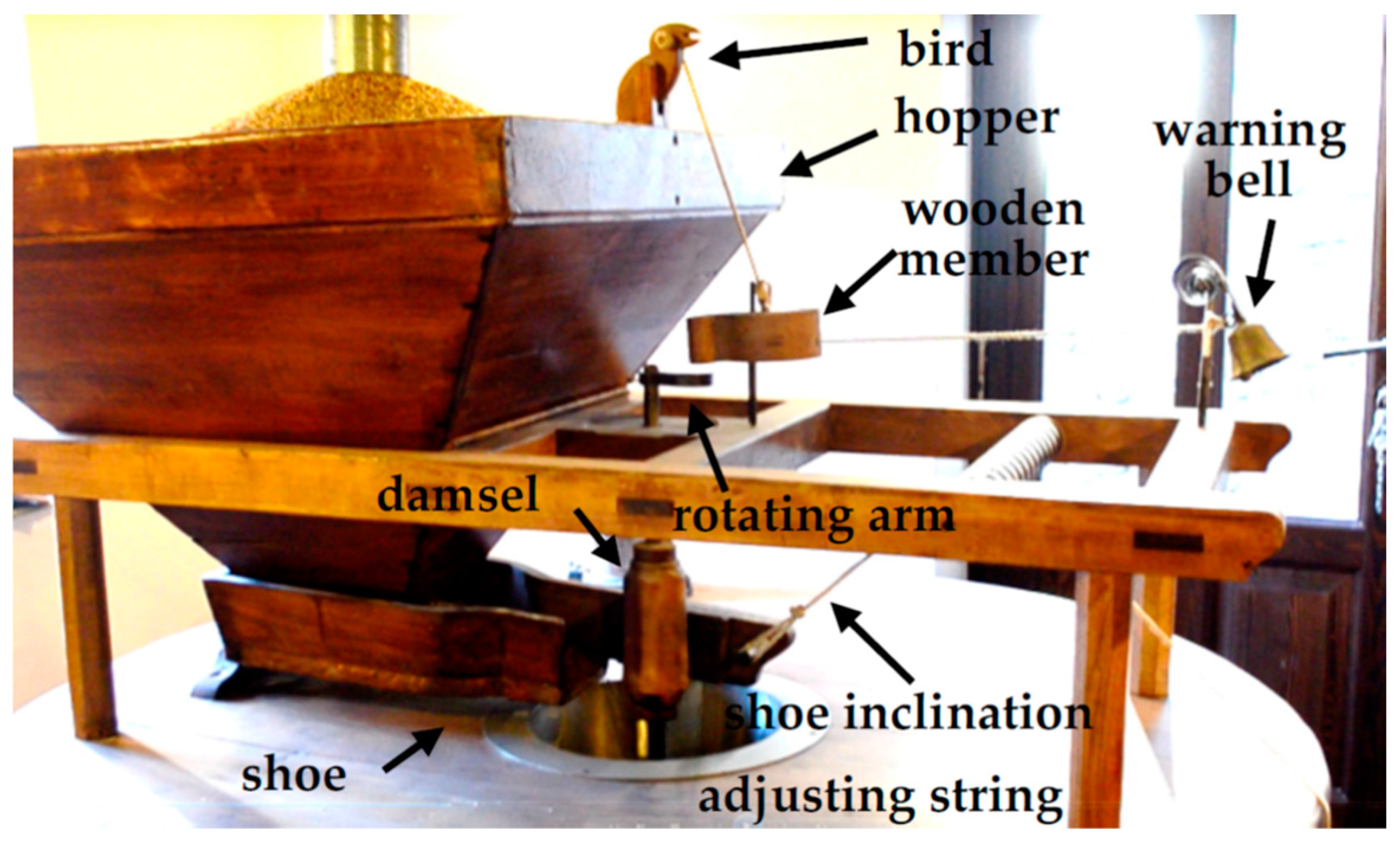
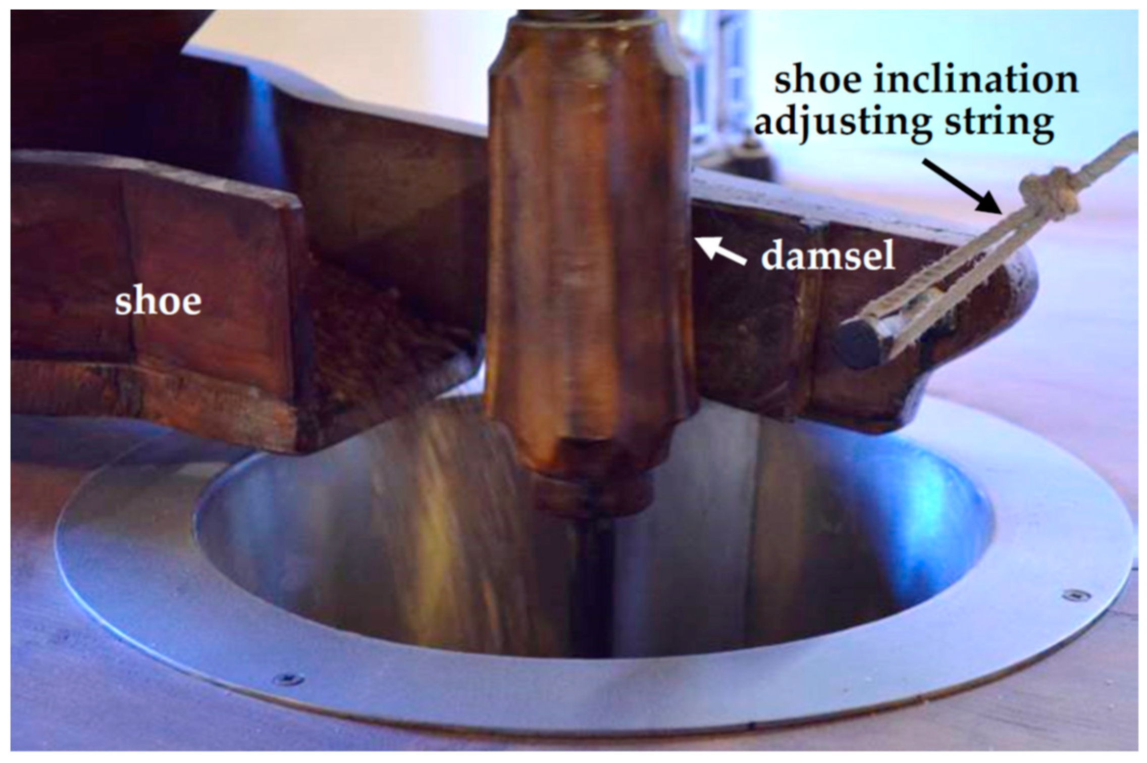
Figure 19a), positioned on the wooden beams of the stone floor, with the function of collecting the flour and conveying it to the plan sifter. The grain, that has to be ground, is loaded into a hopper located at the top of the tun. Due to gravity, the grain falls on an inclined plane (shoe), shaken laterally by a cam (damsel) actuated by a shaft keyed with the runner stone (
Figure 20), so that the oscillation frequency of the inclined plane depends on the rotation speed of the runner stone. This means that the flow of the grain that feed the central hole of the runner stone grows by increasing the grinding rotation velocity. In addition, the grain flow can be adjusted by changing the slope of the inclined plane (
Figure 20) by regulating the length of the string (
Figure 20 and
Figure 21).
To avoid damages to the millstones, it is necessary to ensure that the hopper never completely empties and the grain feeding is never interrupted. With this aim, a curious warning system has been designed. As long as there is a sufficient amount of cereal in the hopper, a wooden bird (
Figure 20) remains in a standing position, held by a rope immersed in the grain (not visible in the figure). In this condition, the wooden member, connected to the warning bell by a string, is not impacted by the rotating arm keyed to the same shaft of the cam shaker. If the hopper gets to low, the rope is released, the bird rotates around a pin, and it puts down the head as if it was pecking. In this way, the wooden element connected to the warning bell goes down, and interferes with the rotating arm that, by striking it, causes the alarm bell to ring during each revolution of the mill stone.
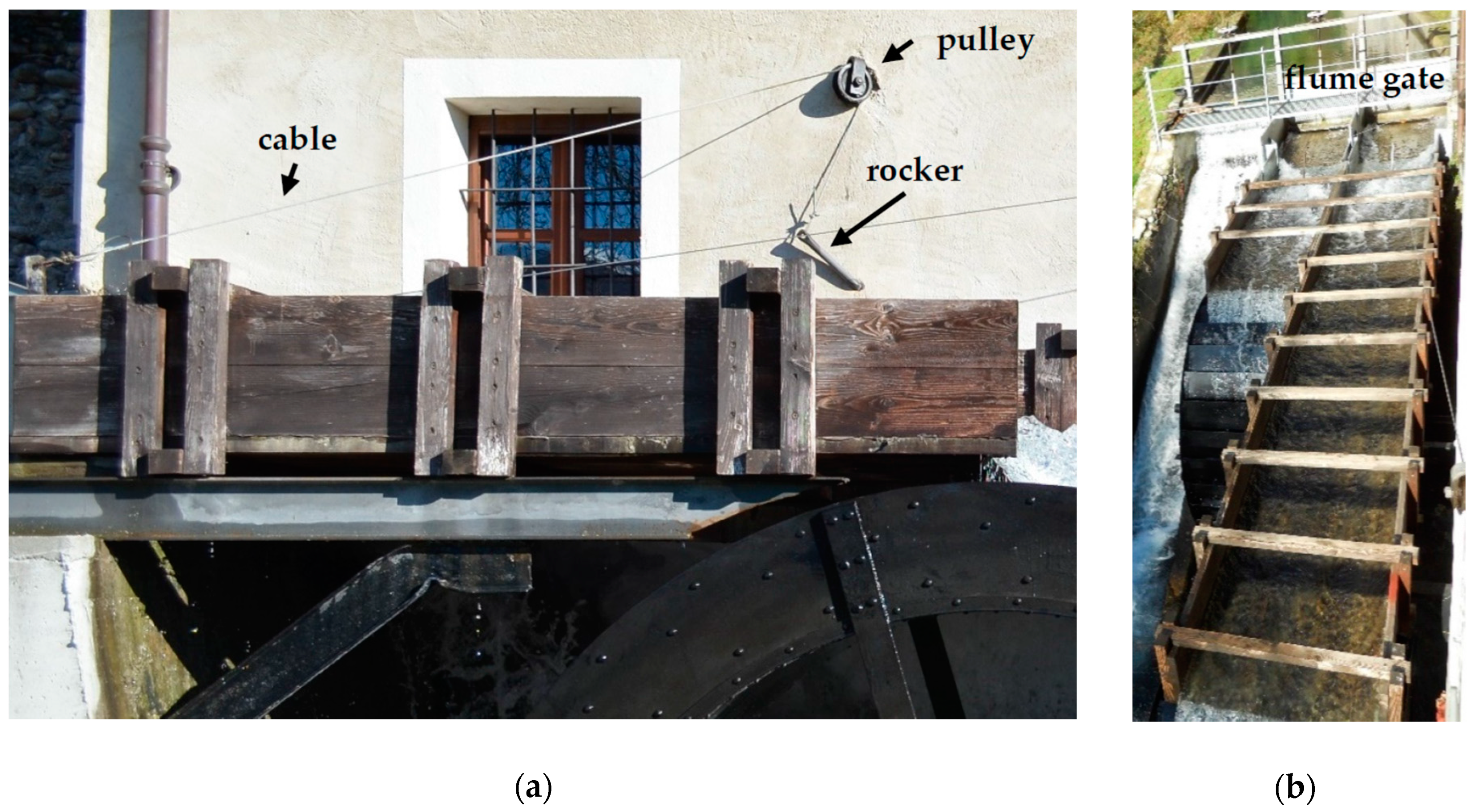
Finally, to obtain good quality flour, it is also important to adjust the grinding speed, i.e., the water wheel supplying flow rate. In the Riviera mill, a regulating lever, positioned inside the build at the stone floor, is integral with an external rocker that rotates in a hole of the mill wall (
Figure 22). A cable is pulled by the rocker, and, through a pulley, closes the flume gate.
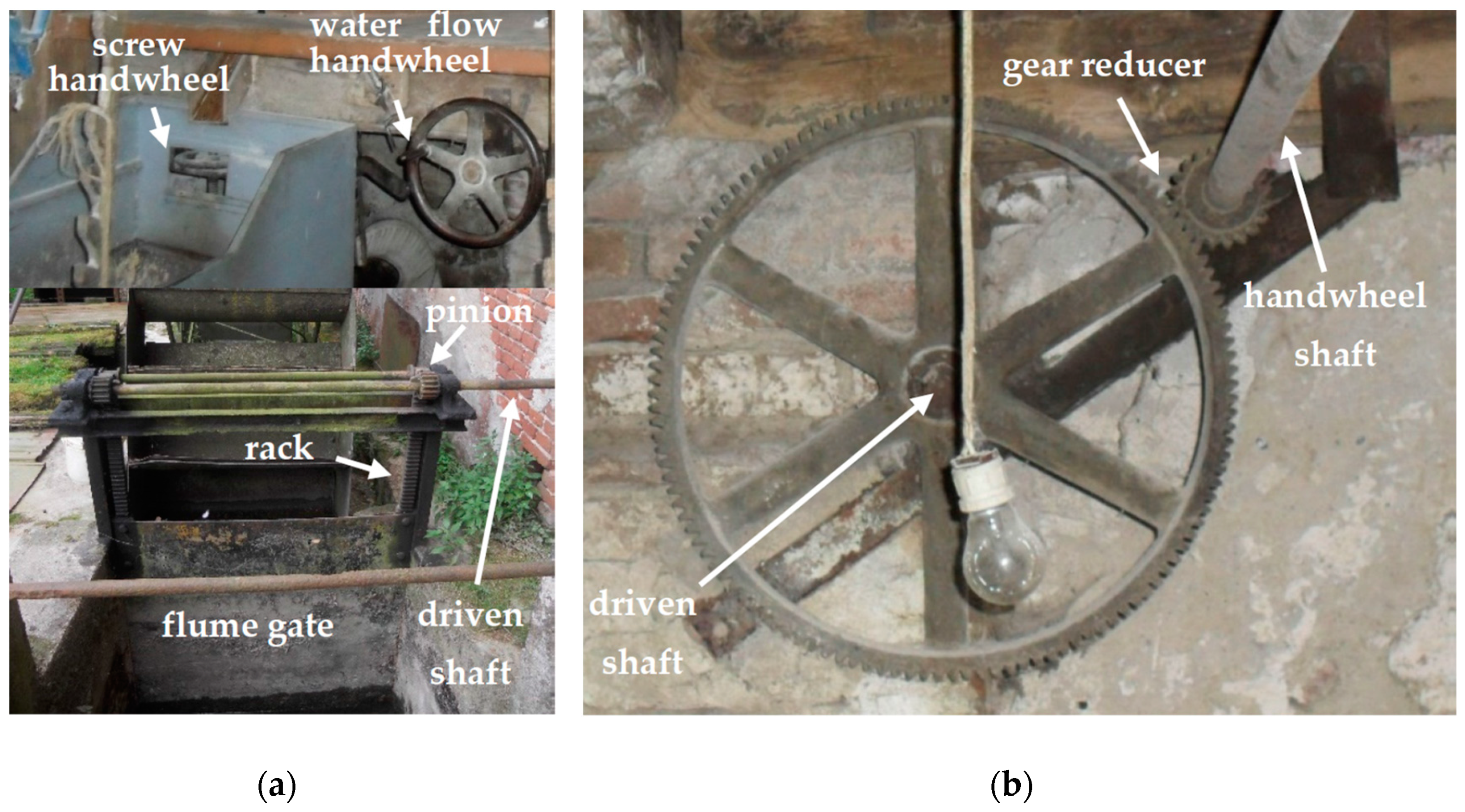
In the case of the Forno mill, a handwheel, positioned on the meal floor (
Figure 23a), is integral with a shaft, keyed with a spur gear (
Figure 23b). The driven gear is integral with a second shaft that pass through the wall of the mill, and is in turn keyed to a pinion in contact with a rack, whose translation regulates the vertical position of the flume gate (
Figure 23a).
5. Conclusions
In the paper, the mechanical architecture of old watermills of Piedmont (Italy) is presented. Beyond the historical value of the work, the authors believe that the knowledge of the functional details of solutions used in the past allows us to fully understand their potential. They can also permit a full recovery of original tasks, as in the case of the Riviera mill, stimulate the design of new hybrid solutions, or inspire original and renewed uses. Old water wheels, for example, when for economic reasons are not suitable for direct actuation of the original machines, could sometimes be renovated for the production of electricity (micro hydropower generators). In fact, these machines present, in general, an interesting efficiency, between 70% and 85% (See
Table 1). In particular, both the water wheels taken as example in this study have a good efficiency, close to 80%, and their restoration or reuse is therefore widely justifiable.
In all cases, for the sake of completeness, to the hydraulic study of the wheel a complete analysis of the mill must be added. In particular, it is necessary: (i) To go into the details of mechanical transmission, (ii) improve some mechanisms that are not very effective, (iii) evaluate the production potential, (iv) model or measure the torque and power characteristics of the whole transmission.
It is not always possible to accurately model the performance of the entire transmission. Water wheels, wooden gears, lubricated plain bearings have an intrinsically non-linear behavior, so that the uncertainty in determining the total efficiency of an old water mill can be significant.
In order to overcome this issue, it can therefore be useful, in perspective, to develop equipment aimed at the in situ experimental measurement of the mechanical characteristic of a water wheel and power transmission, and the definition of its overall efficiency. The portable device should consist of: (i) A unit for the connection with a mill power transmission; (ii) a braking unit capable of generating the load torque; (iii) a measurement unit, appropriately instrumented to determine the torque and power characteristic as a function of the rotation speed of the load shaft.


