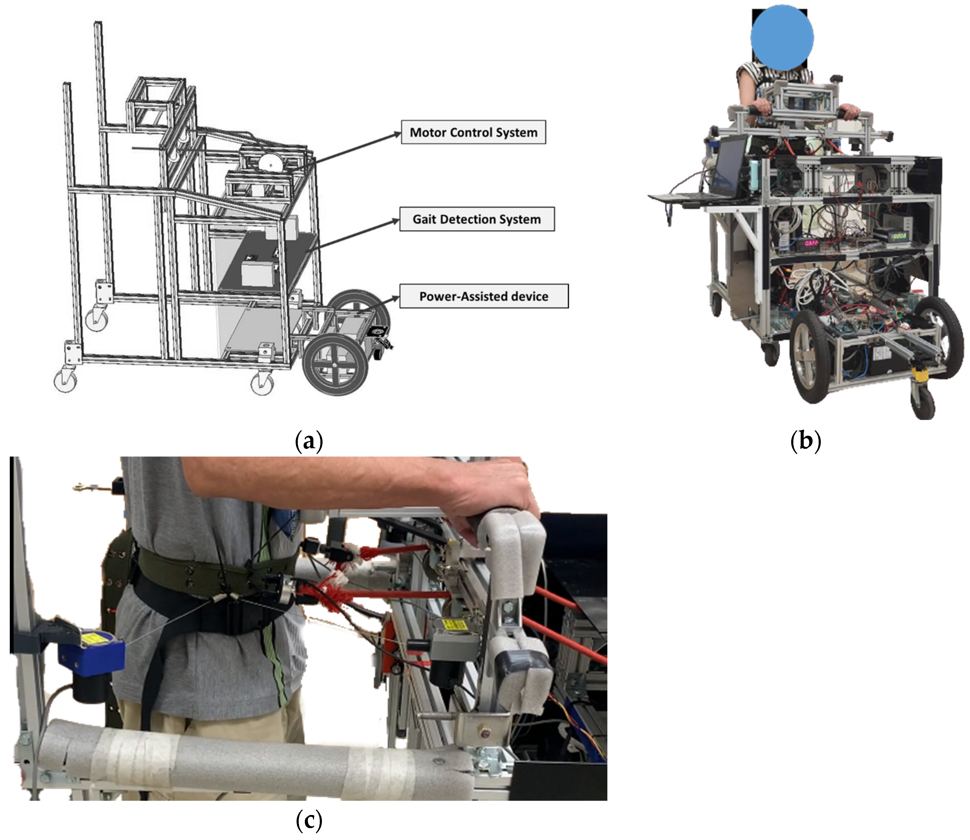
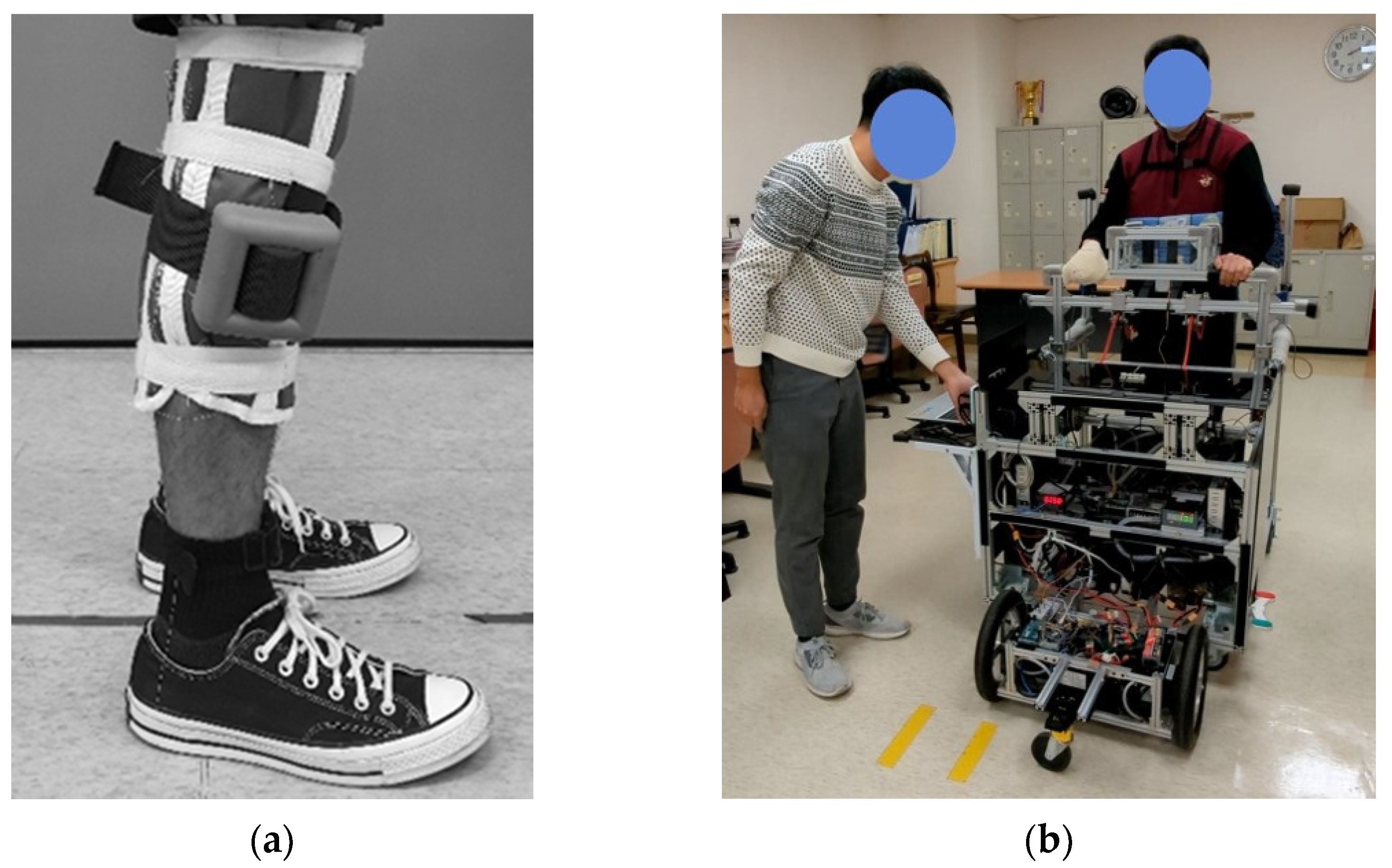
The power-assisted NDT trainer comprises a motor-control system, a gait-detection system, and a power-assisted device, as shown in
Figure 1a. We conducted system identification and control designs for the intervention and power-assisted systems. Then, we recruited subjects to perform clinical experiments, as illustrated in
Figure 1b.
The gait-detection system applies two IMUs attached to the subjects’ lower legs to detect HS events by using the LSTM model, as
Appendix A shows [
16]. It sends a triggering signal to the motor-control system to perform NDT intervention upon detecting an HS. The motor-control system [
20] cues the subject’s anterior superior iliac spine (ASIS) by ropes upon receiving the triggering signals from the gait-detection system, as shown in
Figure 1c. ASIS is a bony prominence located at the front and upper part of the pelvis, where the subcostal nerve lies close and the tensor fasciae latae muscle attaches to its lateral. The power-assisted system comprises a laser-distance sensor and two motors, where the sensor measures the participant’s position and controls the trainer to keep the trainer at a constant distance from the subject. Therefore, the subjects can focus on receiving the NDT training without manually propelling the trainer.
2.1. NDT Intervention by the Motor-Control System
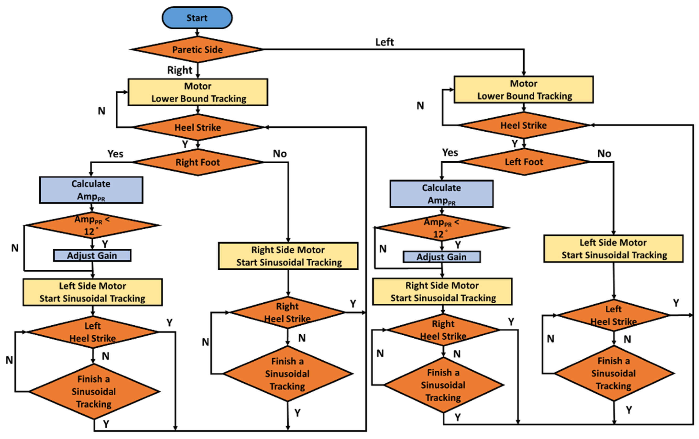
We invited therapists to conduct clinical NDT training and observed their actions. During the training, the therapists guided the subject’s motions by using the ropes attached to the subject’s ASIS. We recorded the therapists’ applied forces and the subjects’ motions to analyze the therapists’ intervention patterns [
14,
18]. First, the therapists applied forces to cue the subject’s opposite ASIS when they observed the subject’s HS. The intervention forces were approximately sinusoidal, as shown in
Appendix A [
18]. Second, the therapist increased the applied forces when they observed insufficient pelvic rotation, as illustrated in
Appendix C [
18]. Therefore, we implemented these intervention patterns to control the NDT motors, as shown in
Figure 2, which produced the corresponding forces to cue the subjects’ ASIS through the ropes. When the gait-detection system identifies an HS, the motor-control system tracks the following command to cue the opposite ASIS [
18]:
where
and
represent the maximum and minimum forces, respectively.
f = 1 Hz. The maximum force is initially set as
= 6 lb and increases to
= 9 lb when the pelvic rotation
is less than
. The minimum force is set as
= 1 lb to keep the rope tight.
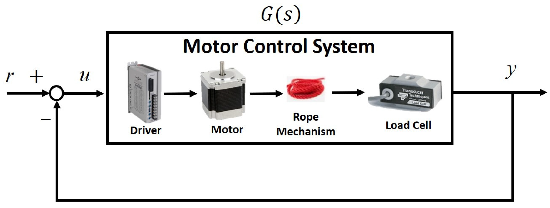
Considering the human factor in the system, we applied robust control to replicate the therapists’ rehabilitation interventions automatically in that robust control has a superior ability to cope with system uncertainty and disturbances. Before control design, we derive the system model by experiments.
Because the rope provided only traction forces, we conducted closed-loop identification. The block diagram of the rope motor-control system is illustrated in
Figure 3, where we sent the swept sinusoidal input signals
r with magnitudes of 1–6 pounds and frequencies of 0.01–2 Hz. We then measured the motor drive signal u and the output force
y. The system transfer functions were then derived by the Matlab command
tfest by using these signals. Considering system variation and uncertainties, we repeated the experiments ten times to derive the following transfer functions:
We applied a gap metric [
21] to select a nominal plant from (2) to perform the robust control design. Suppose a nominal plant
has a left coprime factorization of
, where
. Assume a perturbed system
can be expressed as
, where
. The gap between these two systems,
, is defined as
the smallest that can perturb ,
denoted as [
21]. Hence, we selected
to represent the motor system because it minimized the maximum gap between
and other plants
, as follows:
with a gap of
.
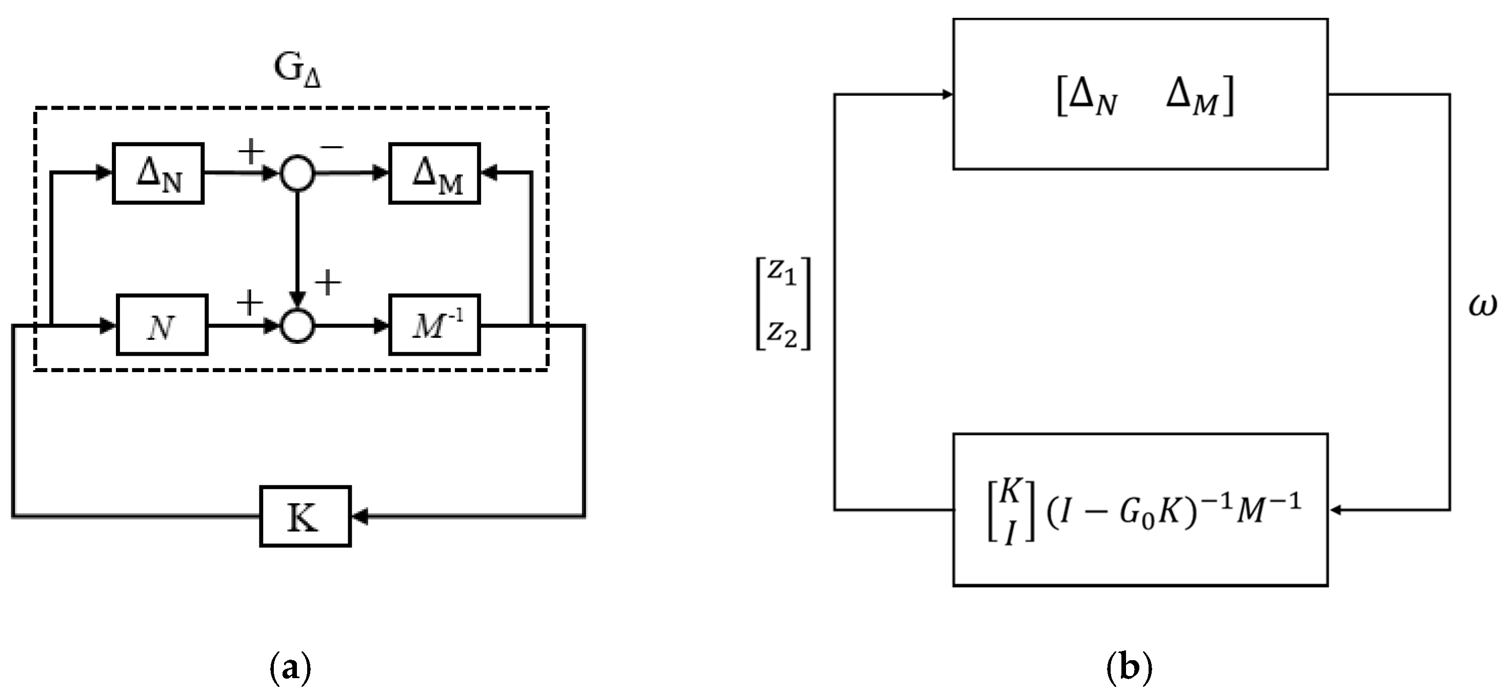
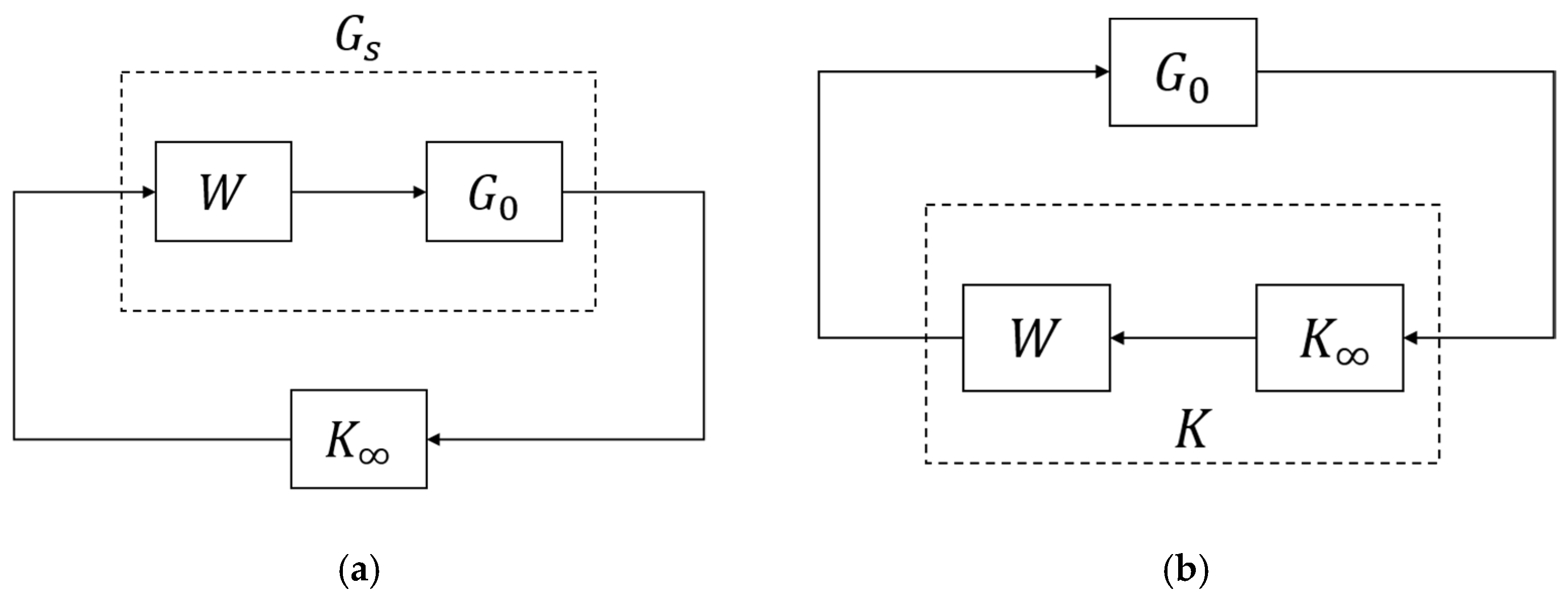
We applied the nominal plant
to design a robust controller. Considering a closed-loop system with a controller
K (see
Figure 4a), we can rearrange the system as the standard block diagram for the Small-Gain Theorem (see
Figure 4b) because system stability is independent of input signals. According to the Small-Gain Theorem [
21], the closed-loop system is internally stable for all perturbations
with
if and only if [
21]:
Therefore, we can define the system’s stability margin
as follows:
So that the necessary and sufficient condition to maintain internal stability for a system
with a perturbation of
, where
, is to design a controller
K that provides a stability margin
. Hence, we must design a robust controller
K for the system
with a stability margin
.
We applied
loop-shaping techniques [
22], as shown in
Figure 5. We set the weighting function
and applied the shaped plant
to design the following robust controller:
The stability margin
exceeded the system gap and guaranteed system stability during operations. Therefore, we applied the shaped controller
to the original plant
, as shown in
Figure 5b.
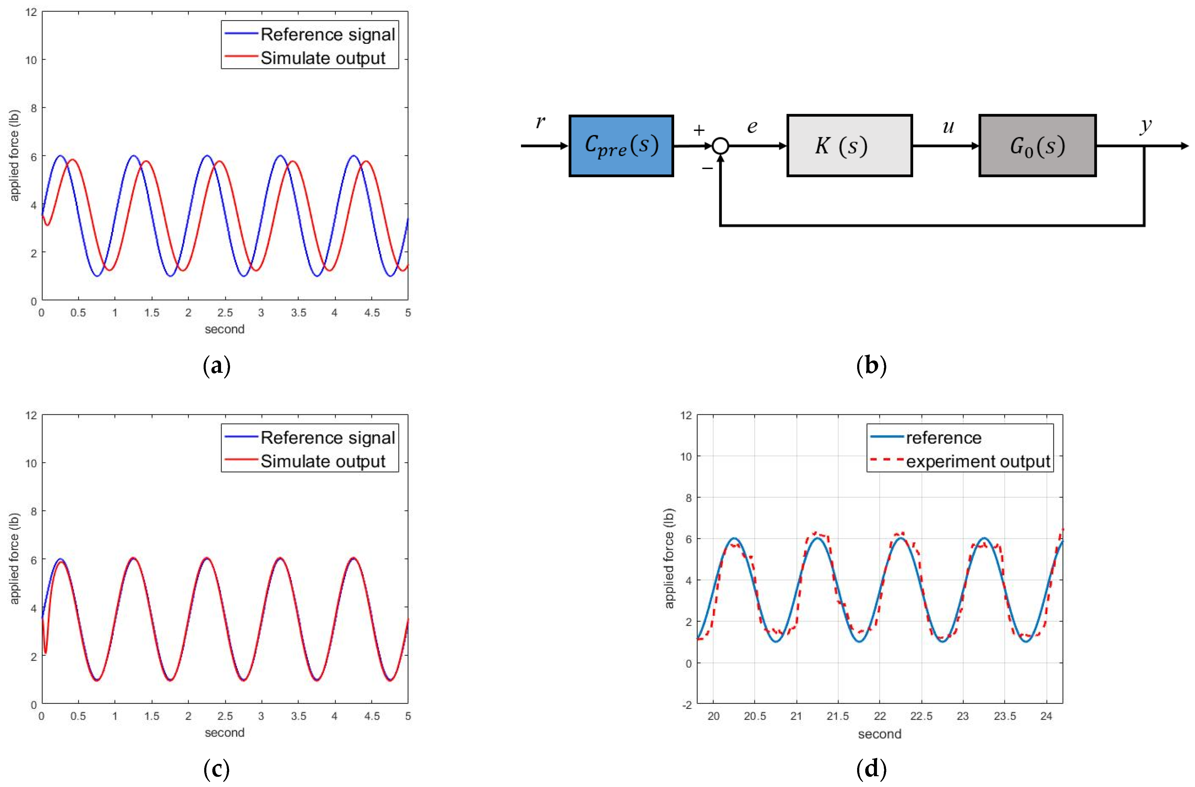
The simulation results are shown in
Figure 6a, with significant phase delay and magnitude decay. Hence, we designed a pre-compensator to modify the responses, as shown in
Figure 6b. Assuming the concerned frequency was 1 Hz, we designed the following pre-compensator:
The simulation results are shown in
Figure 6c, where the motor-control system could track the intervention forces. Therefore, we implemented the motor-control system to track the intervention force commands of (1).
Figure 6d shows the experimental force-tracking responses, where the motor could track the intervention force commands for NDT rehabilitation.
2.2. Control Design for the Power-Assisted System
Figure 7 illustrates the power-assisted device. The main control microprocessor is an Arduino Due [
23], which sends pulse-width modulation (PWM) signals to the wheel motor drivers. The second microprocessor is an Arduino Mega [
24], equipped with an MAX485 communication module to receive feedback signals from the motors and the laser-distance sensor.
We connected the power-assisted device to the trainer and conducted open-loop system identification by experiments. First, we set swept sinusoidal input signals with frequencies of 0.01–2 Hz and converted the signals to the corresponding PWM signals to drive the motors. We then measured the output signals by the laser-distance sensor to derive the system’s model from these signals. We considered system variation and repeated the identification experiments to derive the following transfer functions:
which represented the entire power-assisted device, including the wheels and motor-reduction mechanism.
Similarly, we calculated the gaps between these transfer functions and selected the following nominal plant:
which minimized the gaps between the nominal plant and other plants, with a gap of
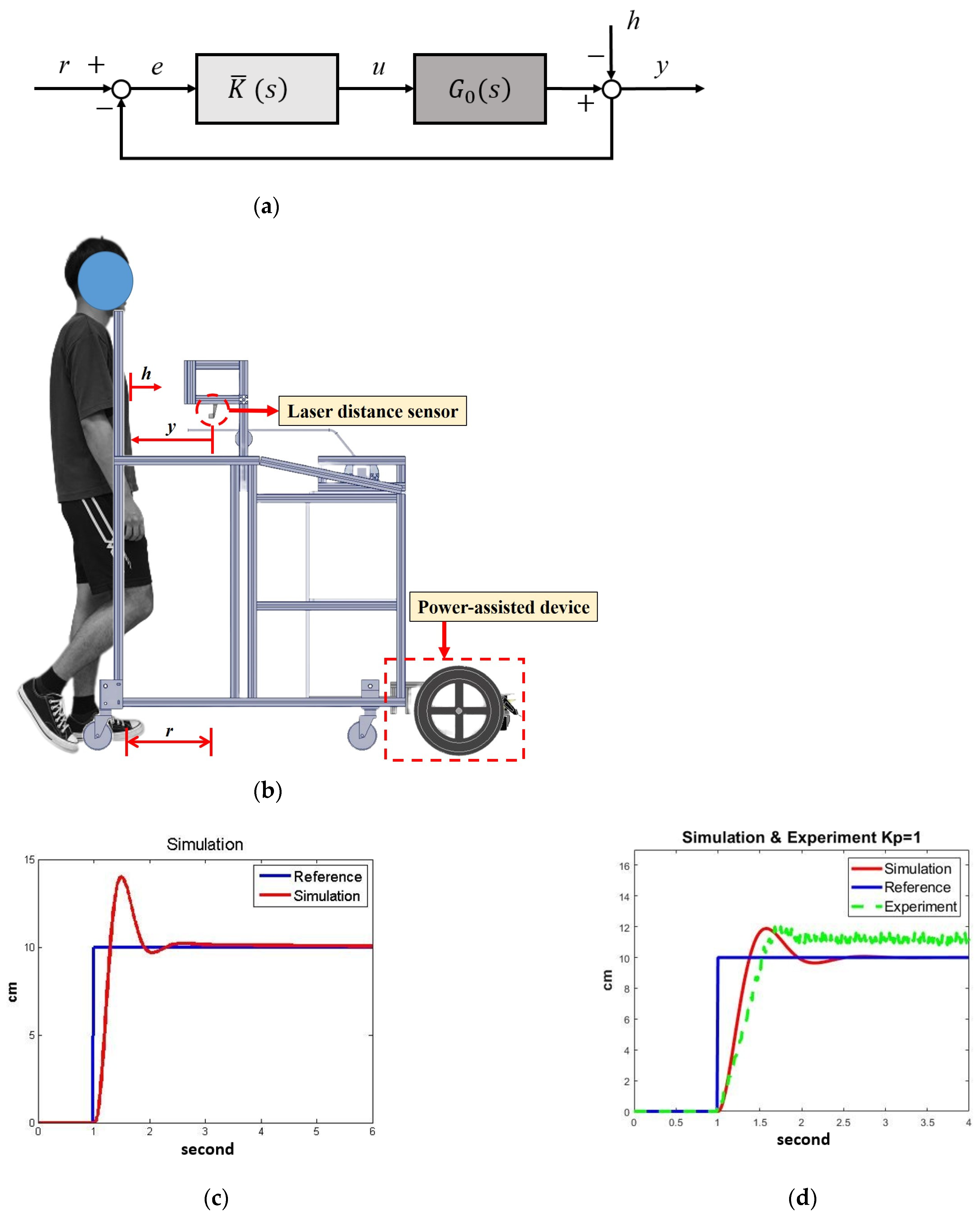
. The power-assisted control is shown in
Figure 8a, where
r is the reference,
h represents the disturbances from human movements,
e is the position error,
u is the motor-control signal, and
y is the actual distance. We first applied robust loop-shaping control to design a controller
that gives a stability margin
.
Based on previous experimental experiences [
15], we set the NDT trainer to maintain a constant distance of
r = 10 cm from the participant, as shown in
Figure 8b. The subject’s movement
h was regarded as a disturbance to the system. The laser sensor measured the actual distance (
y) between the participant and the trainer so that the feedback system could compensate for the position error
e by the motors.
Referring to
Figure 5, we set the weighting
W as follows:
and derived the following robust controller:
We then reduced the weighted controller
to the fifth order, which provided a stability margin
, which exceeded the system gaps and could guarantee robust stability during operation. The simulation results are shown in
Figure 8c, where the significant overshoot and the high-order controller were disfavored. Therefore, we applied gain-scheduling control for the power-assisted system.
The gain-scheduling-control design was conducted empirically because the control signal
u should be large enough to overcome frictions and small enough to avoid overshoots. We tuned the controller gain
and verified its effects iteratively. For example, when
, the stability margin was
with the system response as shown in
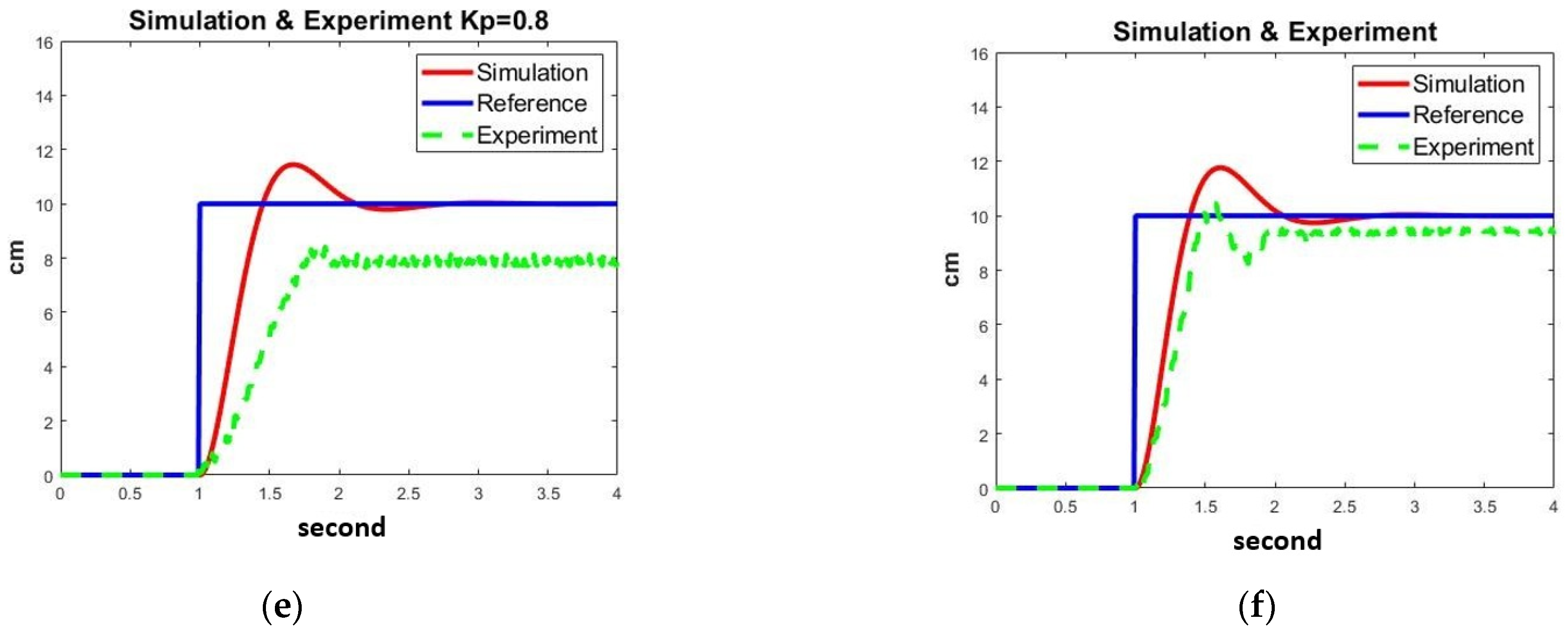
Figure 8d, where the overshoot and steady-state error were significant due to friction. On the other hand, when
, the stability margin was
with the system response, as shown in
Figure 8e, where the steady-state error was negative because of the low gain and friction. Therefore, we designed the following gain-scheduling control:
The simulation and experimental responses are shown in
Figure 8f, where the system responses were satisfactory during experiments despite slight oscillations and steady-state errors. The gain-scheduling control could successfully regulate the NDT trainer, keeping it at a constant distance from the user. Therefore, we applied this controller in clinical experiments.
2.4. Clinical Experiments
We recruited 10 healthy subjects and 12 stroke patients to participate in the experiments. The inclusion criteria were (1) stroke patients with lower-limb paralysis at Brunnstrom stage III to V, whose characteristics are described in
Appendix B. The Brunnstrom stage is used to assess and describe the stages of limb-function recovery in stroke patients. (2) The ability to walk independently and follow commands. (3) Age between 18 and 80 years.
Appendix C illustrates the participants’ statistical data. All participants provided written informed consent before participating in the study.
- (1)
Healthy subjects: The healthy subjects wore a joint restrictor with a 2 kg block on one knee, as shown in
Figure 10a; the joint restrictor constrained their knee flexion to simulate stroke patients’ gait patterns. Each participant performed the following two sets of experiments to validate the effectiveness of the power-assisted device:
- (a)
Experiments without power assistance.
- (b)
Experiments with power assistance.
Each set of experiments contained three stages: stage A (pre-treatment), stage B (during treatment), and stage (post-treatment). First, the subject walked approximately 25 m without intervention at the A stage. Then, the subject walked approximately 50 m with the NDT intervention at the B stage. Finally, the subject walked approximately 25 m without intervention at the stage. There were no breaks between the stages, but the subject could rest if necessary.
- (2)
Stroke patients: The experiments were conducted within a hospital approved by the Cheng Hsin General Hospital. Twelve stroke patients participated in the experiments, walking in a straight line with the NDT trainer at their most comfortable pace, as shown in
Figure 10b.
The stroke patients’ experiments also consisted of three stages. First, each subject walked approximately 44 m without intervention at stage A. Then, the subject walked approximately 88 m with the trainer’s intervention at stage B. Finally, the subject walked approximately 44 m without intervention at stage . Participants completed the procedures consecutively, with the option to rest if necessary during the experiments. Considering the stroke patients’ physical stamina and walking ability, they only conducted one set of experiments with the power-assisted device.

 ,
, 


