1. Introduction
The development of complex mechanisms is linked to the more efficient use of drive aggregates carrying out functions of movement with the requisite parameters. Research and development in the area of drive aggregates has intensified in the search for more effective forms of converting drive power into the mechanism’s performance, drawing on the compact aggregates concept with the required level of intelligence and autonomous actuator properties [
1].
For complex mechatronic devices such as a humanoid robot, a drive aggregate consists of the control, the sensor part, the transformation part, and the electrical motor itself [
2]. The latest developments in actuators for service robotics dictate a compact actuator trend. These actuators are capable of the required flexibility, have their own intelligence and external communication on the bus, and are applicable in distributed control systems such as in autonomous actuators [
3,
4,
5]. To achieve the precise movement of a humanoid robot, the drive must be based on backlash-free gearboxes and the absolute output sensor [
6]. In small precise actuators based on precision gearboxes, it is especially necessary to verify those parameters that may impact the quality of the feedback function. In addition to the standard performance parameters such as the torque range, speed range, efficiency, overloading capacity, and accuracy, it is also necessary to check the functions arising from the application requirements [
7]. A drive moving the humanoid robot’s legs must be checked for pliability, hysteresis, backlash, dead run, kinematic drive errors, evenness of run, friction torque, thermal mode, and the fluctuation of these parameters depending on the position of the output element [
8,
9,
10]. These actuator properties may be checked using the following characteristics:
The deformation characteristic hysteresis curve—expresses the dependence of rotation Δ, ϕ on the load measured on the output flange when the output shaft is in the static position;
Deviation from the evenness of run—expresses the deviation in the run of the output shaft at the even run of the input shaft, depending on the load.
The pose actuator for a locomotive system of service robots is conceptually built as an electrical servo mechanism for the position control of the rotation angle of the actuating mechanism of the robot’s leg, composed of a precision gearbox, the output of which is housed in a precision roller bearing and a servomotor, both composing a compact structure in terms of design and function, positioned on the axial structure with the correct layout and size [
11,
12]. The functionally crucial elements of coaxially arranged aggregate part of the compact drive unit are the electrical motor, the gearbox, the power semiconductor converter for the power supply and motor control, the speed, or position controller. Usually, the speed and position sensors are integral parts of the motor. The module’s properties and parameters are represented by its output member [
13]. The drive part of the actuator must allow for a four-quadrant operation, i.e., in both the rotation and the torque directions. The actuator works in a closed feedback loop. The position control is either targeted (optimal position setup) or monitored (change in position optimal in terms of time) over as short a time as possible, following the set trajectory under a precisely set speed [
14]. When the output speed changes frequently, it is impossible to optimize a motor and fixed-ratio transmission system for the size, performance, and efficiency at the same time: the fixed ratio of the transmission causes substantial losses within the motor. For instance, a high-quality electric motor may be 90% efficient when operating under high velocity and low torque, but in robotic applications, the system must instead be designed to achieve the needed peak torques and speeds in the smallest package possible, resulting in a system that almost never operates near its peak efficiency [
5].
The purpose of the scientific research described in this paper is to design, verify and optimize the parameters of the actuator so that it can withstand a greater load with higher accuracy than a standard actuator.
2. Structure of the Actuator
An actuator is a part of a device or machine that helps it achieve physical movements by converting energy, often electrical, air, or hydraulic, into mechanical force. Simply put, it is the component in any machine that enables movement.
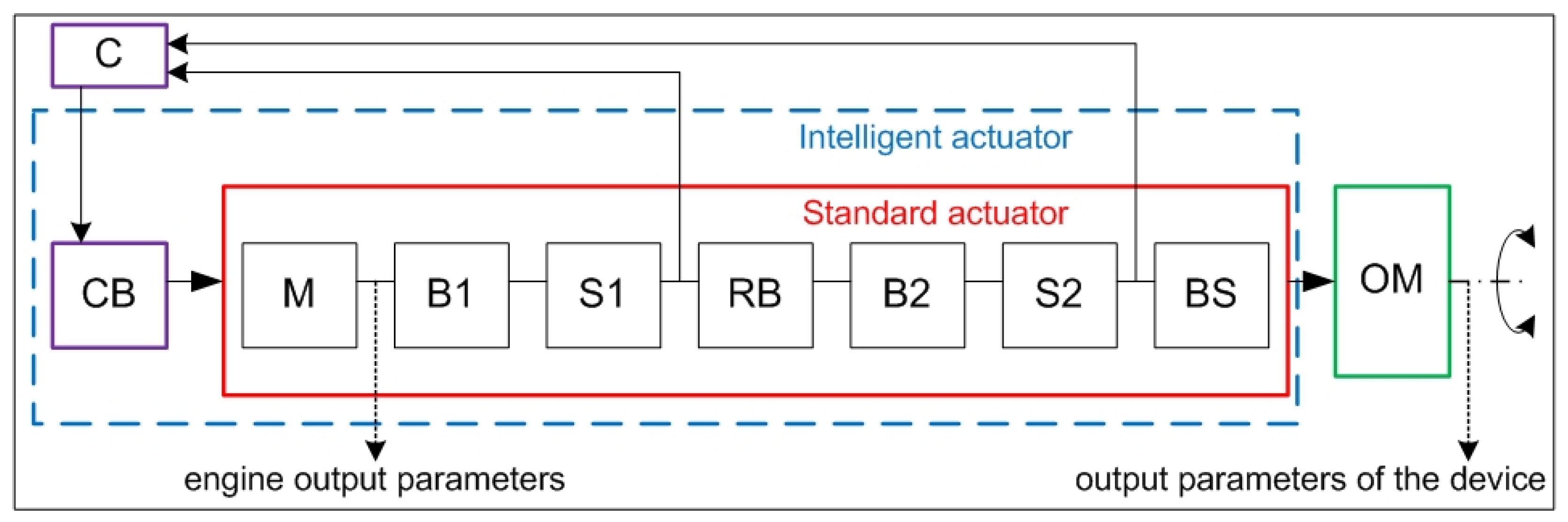
The actuator’s system model with a transformation mechanism also describes the inner structure of the actuator design (complete block diagram), built on system elements (module’s basic inner functions), as shown in
Figure 1. The individual components of the actuator system model are as follows: C—control; CB—control block; M—motor; RB—gearbox; BS—housing; S1, S2—sensors; B1, B2—brakes; and OM—output member.
Typical in the function and operation of a precision gearbox actuator is the simultaneous engagement of several actuating elements (teeth). Each individual engagement is affected by the transmitted load and auxiliary load resulting from the real geometric and kinematic precision of functionally crucial gearbox elements (manufacturing the deviations of the engaging elements, mounting the deviations of crucial elements, etc.) [
15]. This is why it is recommended for the mathematical transmission model to also take into account the effects of the statistical distribution of the inaccuracies affecting the course of the pliability. As the simulation model of a precision actuator, a model with linear springs connected in parallel has proven to be useful, with the springs representing the individual engaging elements [
16]. The probability of contact (engagement) between two engaging elements depends on the load and manufacturing inaccuracies, and may be considered nonlinear. Typical parameters and features may be expressed by the real backlash of each individual pair of engaging elements, which may be expressed by the following dependence
ζ = s0 − ξ, where
s0 is the mean backlash value of the engaging elements and
ζ is a random manufacturing deviation from the required mean value
ξav = 0.
For the set of values
ξ upon the simultaneous engagement of a large number of engaging elements, we can note the distribution function of the probability of occurrence of value
ξ in the interval
<−∞, X>:
where
σ is the standard deviation of the set of values
ξ, ζ.
When the gearbox comes under the load, the gradual engagement of several contact points occurs and their rigidities add up until the moment in which all engaging elements come into contact, when the rigidity reaches its maximum [
17,
18]. For the actuator, the course of the deformation property, expressed as a theoretical dependence of the gearbox rigidity, should also account for the rigidity of other related elements in the case of the actuator (shaft, clutch).
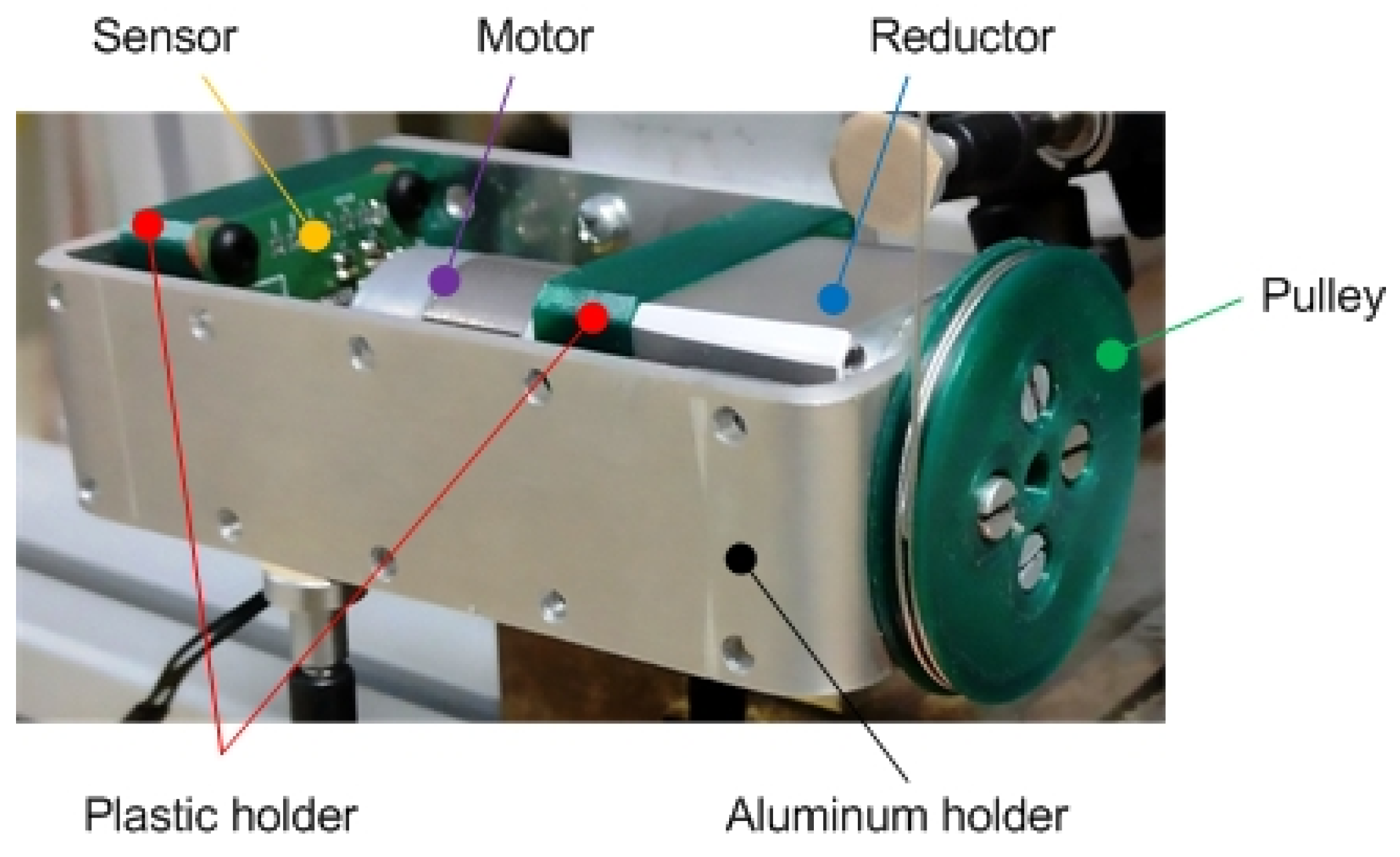
The newly developed actuator (A1) consists of an electrical motor of our own design, a harmonic CSF-8-50-1U-CC-F gearbox [
19], a rotation speed sensor AS5048, and structural elements. The checked actuator’s design utilizes a combination of metal and non-metal materials. Non-metal components are 3D-printed from polylactic acid (PLA).
Figure 2 shows the new actuator with the description of its main components.
The selected parameters of the developed actuator are as follows: output power—12 W; rated speed—6040 min−1; rated torque—19 mNm; engine weight—55 g; operating temperature range—45 °C; motor diameter—24.2 mm; and engine length—45 mm.
To check the suitability of the selected methodology as well as the need to replace the actuators used to date, a commonly available actuator on the market was chosen, commonly used at the workplace, to verify the small actuators’ properties [
20].
The selected parameters of the new actuator—A1—and the used actuator—A2—are listed in
Table 1, where (arcmin) represents the unit of an angular measurement equal to 1/60 of one degree.
3. Methodology of Measurement
In designing the methodology of measurement, we drew on the expected deployment of the checked drive. Since the drive is intended to drive the joint of a humanoid robot, the choice of methodology was that of the ISO standard 9283. This standard enables the verification of various characteristics. Since verification is performed on a drive equipped with the respective gearbox without the drive being housed on the robot’s body, it was necessary that the verification according to the said standard was modified. The modification consisted of simplifying the process of reading the needed characteristics.
The selected measuring tests are based on the ISO standard 9283 targeting “Handling industrial robots—Working characteristics and the respective testing methods” [
21]. Methodology sheets were prepared to complement the proposed set of measurements and tests which, once completed with the measured values, enable the simple generation of a set of measuring protocols as an integral part of the actuators measuring protocols.
To establish the basic data of the actuators to be checked, two characteristics were selected from the said standard, namely the pose accuracy (AP) and pose repeatability (RP). A slight modification of the methodology compared to a standard procedure followed by measuring the industrial robots’ parameters was made, since the actuators were not placed inside the robots’ joints. The modification stemmed from the need to obtain the measured data relevant for establishing the RP values. The actuators moved +100° in the positive direction and returned in the negative direction to the initial position, with the sensors in position no. 1 (0°) and position no. 2 (+90°). Position no. 3 (+100°) does not contain a sensor, as it is only a position to which the actuator is turned, so that it is possible to work with the hysteresis of the motor and the harmonic reducer during the measurement. Data for AP verification were sought in positions no. 1 and no. 2, respectively; in other words, in actuators’ position 0° and in position + 90°. The first value for RP verification was taken in position no. 1 (0°) (same position/value as in the AP case). This was followed by the actuator’s movement by +100° to position no. 3 (100°). Subsequently, the actuator was returned by the value of −10° to position no. 2 (90°), where the second RP measurement was performed. This resulted in finding more precise data on the actuator’s hysteresis in both the positive and negative directions. The result of the measurement is a set of 90 measured data. The measurements were performed at the maximum rotation speed of 50 rpm.
An overview of the selected tests of working characteristics and the respective parameters of both actuators is shown in
Table 2. Since a higher torque value was expected in the new actuator A1, the value of 1.73 Nm was used in measurement. The torque value of the A2 actuator was 1.26 Nm.
3.1. Description of Selected Characteristics
Pose accuracy (AP)—is the difference between the programmed position and the average of positions actually achieved by the actuator’s end member. To assume the programmed position, the actuator’s end member must always approach it from the same direction. Sensors are placed on two axes (X, Z) perpendicular to each other.
The pose precision (AP) in one direction is calculated from the measured values on axes X–Z from the following equations:
where (
xc, zc) are the programmed values and (
xj, zj) are the real (measured) values. Whereas:
This results in the value of the actuators’ accuracy in one direction:
Pose repeatability (RP)—expresses the degree of a match between the locations of the positions achieved after n-repetitions of movement into the same programmed position in the same direction.
From the measured values, the RP value is calculated as a sphere radius, the center of which is a barycenter according to the equations below:
where
The barycenter coordinates of the points achieved at n-repetitions of the same position are calculated from Equations (4) and (5).
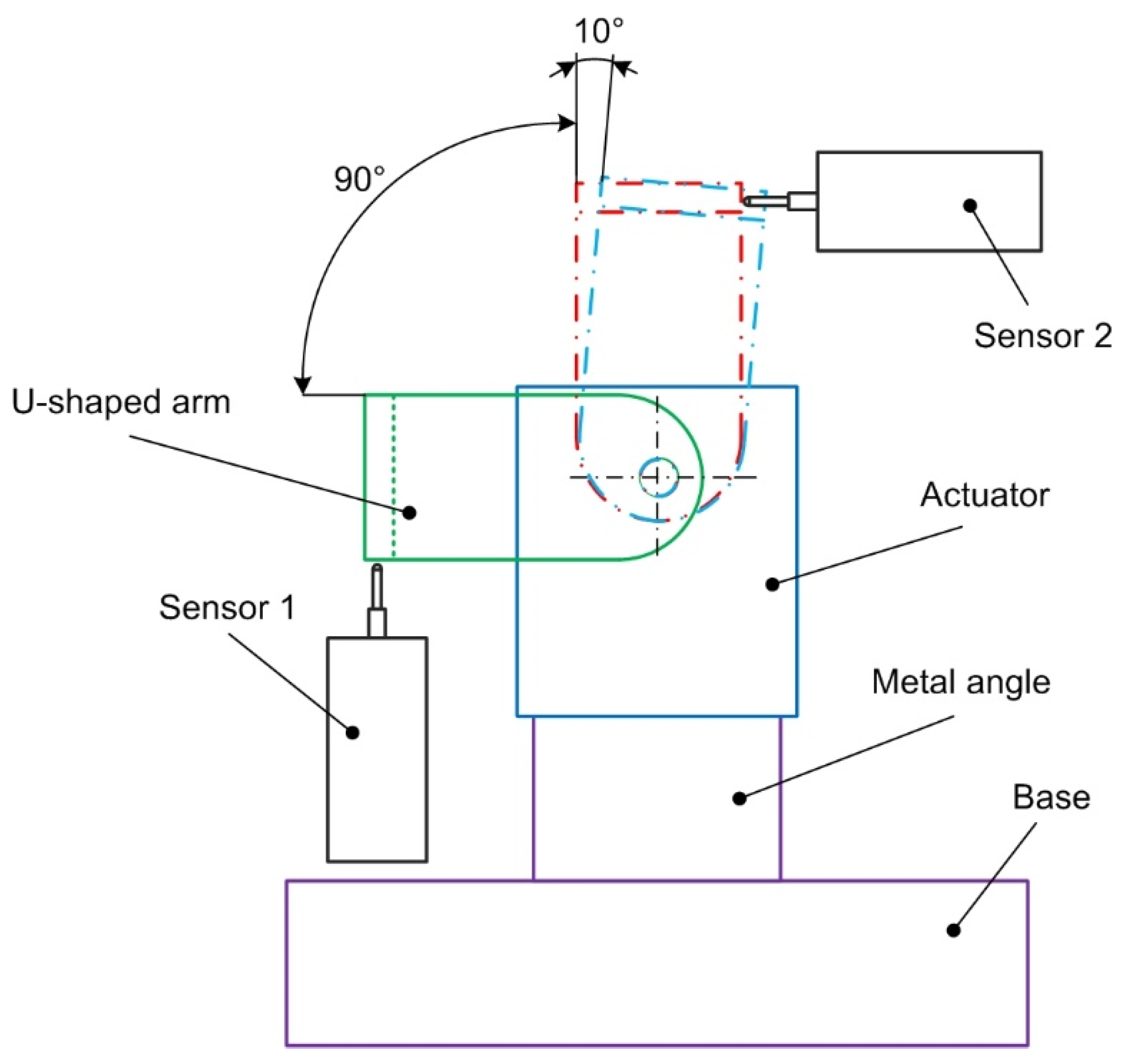
To ensure the comparable conditions of the comparison drawn between the A2 actuator and the newly developed A1 actuator, it was necessary to design a measuring stand. The measuring stand of our design consists of a sufficiently rigid foundation plate placed on a structure made of an Aluminum Profile System. Since the recommended torque value achievable by the A2 actuator shown in the chart is 1.26 Nm at 12 V, the stand’s design was adjusted to account for those parameters. The actuator was fastened to the stand with an angle metal with a 4 mm thick wall. The reading technology used to check the actuator consisted of two Heidenhain MT 12 contact sensors and two Heidenhain VRZ 401 imaging units [
22].
Figure 3 shows the placement of the actuator and both sensors. Other components are also shown in the figure, as is the range of the actuator’s movements.
3.2. Measurement Preparation
Following the ISO standard 9283 methodology for finding one-directional pose accuracy, the measurement had to be performed under the maximum load [
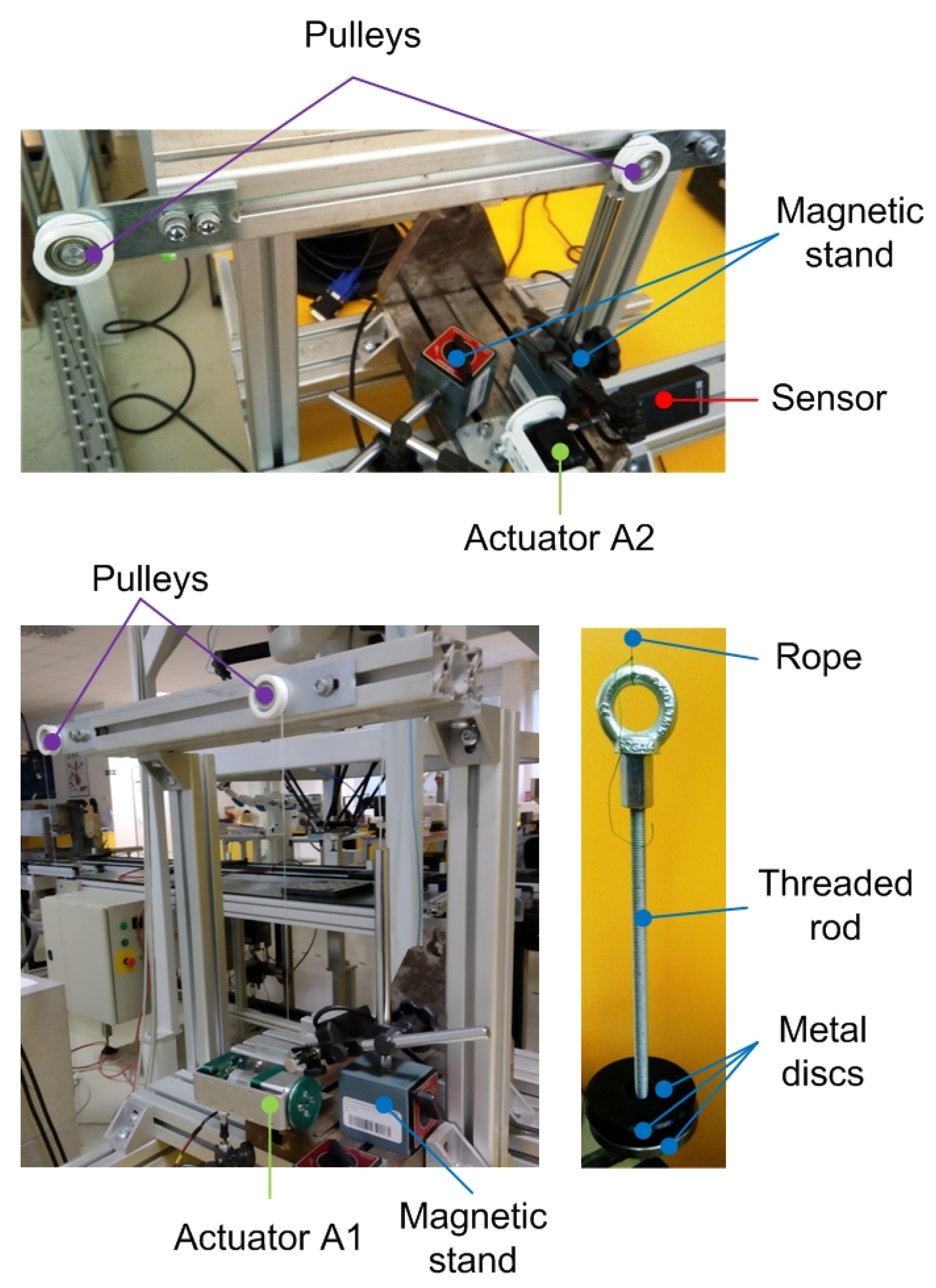
23]. In addition, the standard allows for performing optional measurements under 50% and 10% loads, respectively. To ensure gradual loading from 10% all the way up to 100%, a system using a set of two auxiliary pulleys, a string, and an interchangeable weight, was designed [
24]. The value of the maximum value of interchangeable weight for reaching the 100% load was 5.4 kg. To ensure the proper load placement on the actuator in the axis of its rotation, a pulley was designed and then 3D printed, measuring 46 mm in diameter. The pulley was fastened with 4 pcs of screws to the drive in the axis of rotation, which ensured the even load placement on the actuator throughout the entire period of its rotation.
Figure 4 shows two auxiliary pulleys (white color) fitted with ball bearings, for weight attachment, and the view of the main pulley (green color) placed on the actuator’s structure.
Following ISO standard 9283, to obtain relevant data, the ambient temperature was 20 °C (+/−2 °C). Further steps taken in preparation of the measurement are as follows:
The actuator is placed on the measuring stand in the horizontal position;
A pulley is placed in the actuator’s axis, with a steel wire fastened thereto;
The wire passes through the two auxiliary pulleys. At the end of the wire, a weight is attached, with the value of 10%, 50%, or 100% of the permissible load.
Two Heidenhain MT 12 contact sensors are in touch with the actuator’s console from two sides perpendicular to each other.
The actuator is supplied with 12 V and does 15 warm-up movements to reach the operating temperature.
The calibration (resetting) of the measured values is performed on the VRZ 401 imaging units.
The actuator is set to a +45° position (this is an auxiliary position with no sensors contact).
3.3. Measurement Procedure
In the case of the ISO standard 9283 recommendation, the same data from 30 measurements are used to check the AP and RP parameters. In our case, we wanted to check the actuators’ parameters in two modes. That is why two different measurement modes are mentioned.
The first mode monitors the actuator turning by +/−90° in one direction, for which the AP measuring methodology was used.
Once the measurement preparation is complete, the measuring procedure is carried out as follows.
- 1.
Mode: The programed cycle of actuator rotation is initiated and the AP is measured:
Step 1: the actuator turns by −45° from the auxiliary to measuring position no. 1, at a rotation speed of (10; 25; 50) rpm;
Step 2: once the actuator stabilizes in the position, the value measured in position no. 1 is recorded;
Step 3: the actuator turns by + 90° at a rotation speed of (10; 25; 50) rpm;
Step 4: once the actuator stabilizes in the position, the value measured in position no. 2 is recorded;
Step 5: the actuator turns by −90° at a rotation speed of (10; 25; 50) rpm;
Step 6: repetition of steps 2–5 (for a total of 30 repetitions).
The other mode works with the actuator turning by 100° with the recording of the respective position also being performed at 90°. The actuator carries out a movement by 100° and subsequently returns by 10°. This mode is selected to record the actuator’s hysteresis [
18] and it applies the RP methodology as set out in ISO 9283.
Once the measurement preparation is complete, the measuring procedure is carried out as follows.
- 2.
Mode: The programed cycle of the actuator rotation is initiated, and the RP is measured:
Step 1: the actuator turns by −45° from the auxiliary to measuring position no. 1 at a rotation speed of (10; 25; 50) rpm;
Step 2: once the actuator stabilizes in the position, the value measured in position no. 1 is recorded;
Step 3: the actuator turns by + 100° at a rotation speed of (10; 25; 50) rpm;
Step 4: the actuator turns by −10° at a rotation speed of (10; 25; 50) rpm;
Step 5: once the actuator stabilizes in the position, the value measured in position no. 2 is recorded;
Step 6: the actuator turns by −90° at a rotation speed of (10; 25; 50) rpm;
Step 7: repetition of steps 2–6 (total of 30 repetitions);
4. Results
To compare whether the checked actuator attains the parameters required and guaranteed or expected by the manufacturer, the following procedure was established. The values separately calculated in each of the 30 measurements were not compared. Only the average AP value was compared. The reason was that only one prototype of the newly developed actuator was available, not to be damaged during testing, as further tests were scheduled for the device. The 3D-printed drive components did not reach such total system rigidity parameters, especially due to insufficient heat dissipation. The heat management of the new actuator was subsequently subjected to another analysis and based on the obtained data, whilst modifications will be made to the new drive’s design. The measured data of the gradually increasing temperature, measured on the plastic holder (
Figure 2) between the engine and the gearbox during 30 measurements, were in the range of 20 °C–62 °C. At a temperature of approximately 52 °C, it was necessary to ensure the cooling of the material by connecting a small fan so that the temperature did not exceed 55 °C.
The parts of the paper below only mention the measurements performed at 50% and 100% loads placed on the actuators.
4.1. Pose Accuracy (AP)
Having conducted 30 measurements under half (50%) and full (100%) loads of the actuators and having calculated the measured data using Equation (6), we arrived at the following average values for one-directional pose accuracy (AP
50) in
Table 3, and for (AP
100) in
Table 4. The values
and
represent an average value of 30 data measured in the X and Z directions of the A1 and A2 actuators under half the load
;
and under the full load
;
according to Equations (4) and (5), respectively, and the procedure stipulated for AP in
Section 3.3.
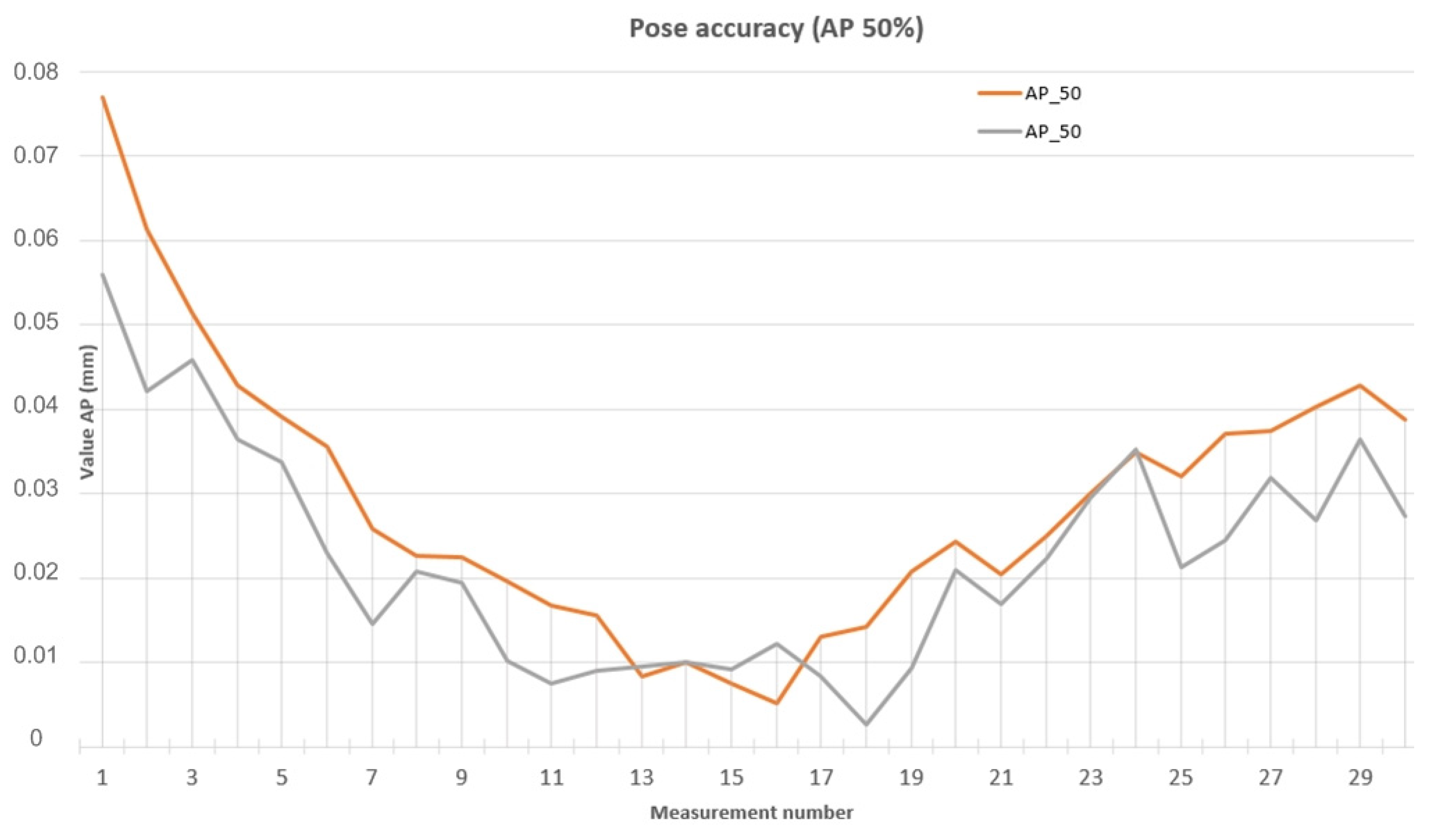
The manufacturer-guaranteed backlash value for A2 is 0.144 mm, which is more than the average measured AP
50 value (0.10381 mm), as listed in
Table 3. The expected value of the new A1 actuator is 0.072 mm and the average measured AP
50 value is (0.065 mm), listed in
Table 3, which confirmed that the proposed actuator satisfies the requirements.
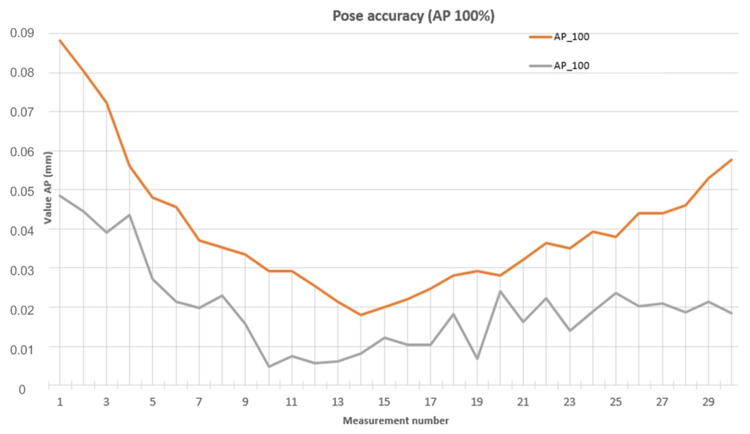
The manufacturer-guaranteed backlash value of A2 is 0.144 mm, which is also more than the average measured AP100 value (0.10435 mm). The expected value of the new A1 actuator is 0.072 mm and the average measured AP100 value is (0.05377 mm) which, again, confirmed that the proposed actuators satisfies the requirements.
The comparison of the data calculated for the A2 (AP_50) actuator positioning accuracy in one direction and that of the A1 (AP_50) actuator in each of the 30 measurements performed with the actuators under half the load is plotted in
Figure 5.
The comparison of the data calculated for the A2 (AP_50) actuator positioning accuracy in one direction and that of the A1 (AP_50) actuator in each of the 30 measurements performed with the actuators under the full load is plotted in
Figure 6.
4.2. Pose Repeatability (RP)
Having conducted 30 measurements of the actuators under half (50%) and full (100%) loads and having calculated the measured data using Equation (7), we arrived at the following average values of pose repeatability in one direction (RP50), as listed in
Table 5, and in (RP100), as listed in
Table 6. The
and
values represent the average values of the 30 data measured in the X and Z directions of actuators A1 and A2 under half the load
;
and under the full load
;
, according to Equations (4) and (5), respectively, and using the procedure stipulated for RP in
Section 3.3.
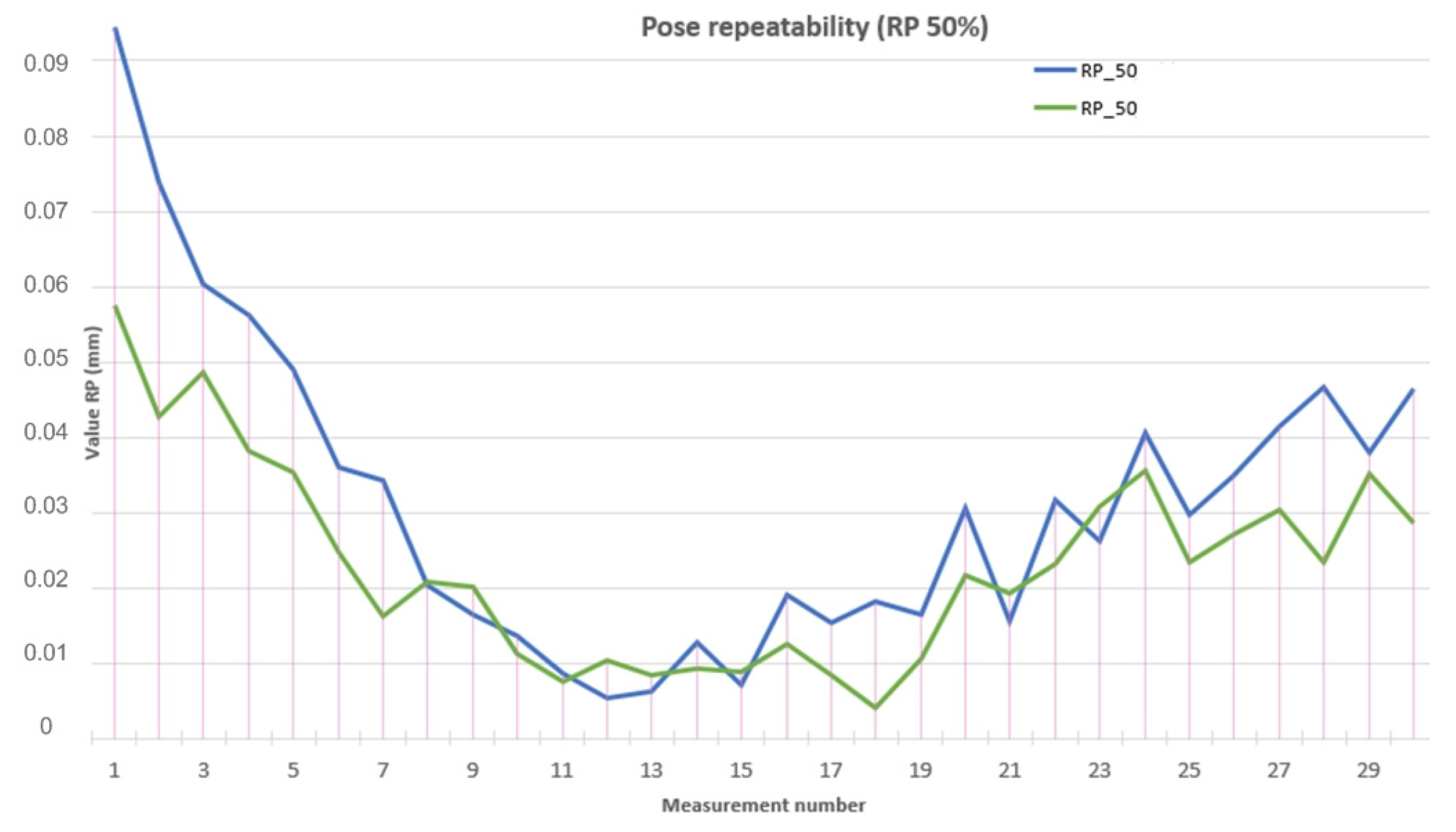
The manufacturer-guaranteed backlash value of the A2 actuator is 0.144 mm, which is more than the average measured RP50 value (0.09447 mm), as listed in
Table 5. The expected value of the new actuator A1 is 0.072 mm and the average measured RP50 value (0.06309 mm), as listed in
Table 3, has confirmed that the designed actuator satisfies the requirements.
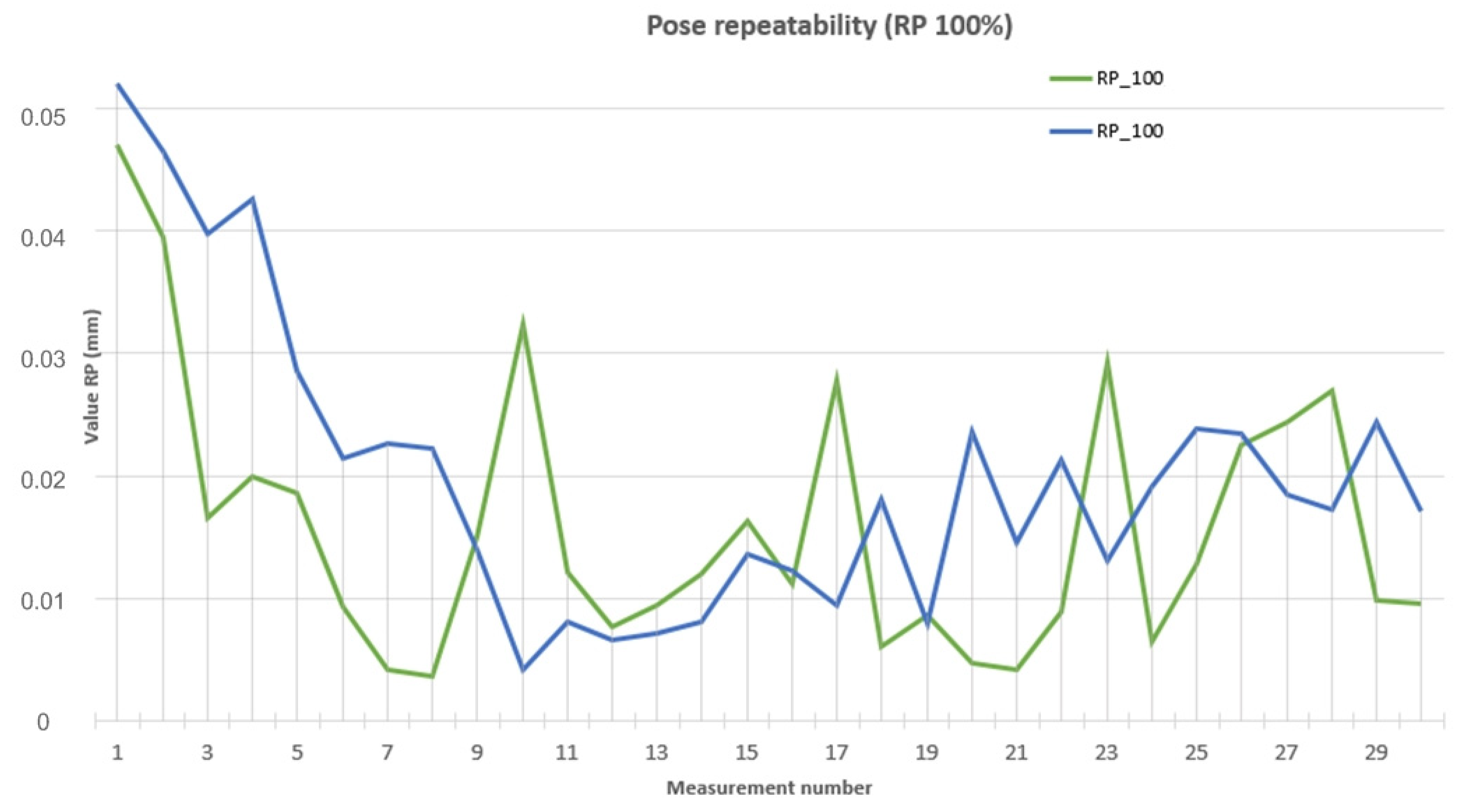
The manufacturer-guaranteed backlash value for the A2 actuator is 0.144 mm, which is more than the average measured RP100 value (0.10435 mm). The expected value of the new A1 actuator is 0.072 mm and the measured average AP100 value is (0.5377 mm) which has, again, confirmed that the designed actuator satisfies the requirements.
Plotted on
Figure 7 is the comparison of calculated data of the one-directional pose repeatability of the A2 (RP_50) and the new A1 (RP_50) actuators in course of 30 measurements in the direction of the axes (X), (Z) under half the load.
Plotted in
Figure 8 is the comparison of the calculated values on the one-directional pose repeatability of the A2 (RP_100) and the new A1 (RP_100) actuators in each of the 30 measurements conducted on actuators under the full load.
5. Discussion
When evaluating the measured and calculated AP data, it was found that when fully loaded, both actuators attained the average AP at the level comparable with half the load. The difference lay only in the range of the maximum and minimum values calculated. A significant difference in deviations in the beginning and at the end of the 30 measurements was attributed to unsatisfactory heat dissipation. Further investigation confirmed that the addition of cooling substantially reduced the differences between the first and the last measurements in the new actuator A1. When the same conditions of additional cooling were set for the reference (old) actuator A2, the difference was smaller by tens of percentage points.
In the next stage of the research, an adjustment to the material will be made, regarding the load-bearing structural compounds of the new actuator. The change will consist of using a lightweight and strong material, replacing the previously used 3D-printed PLA. The proposed material will be an aluminum alloy formed into a desired shape. The use of this material should solve two major problems that the first prototype suffered from. Its first problem was that of the insufficient rigidity of the system, manifested in the need to repeatedly tighten the bolts holding together the individual actuator parts. The bolts were loosened, especially due to periodic cyclical strain of the 3D-printed material. The other reason was the propagation of heat from the motor to other actuator parts. Heat propagation was different depending on the different materials used, which demonstrated the increased thread holes housing zinc-coated bolts under the maximum load and at the maximum actuator movement speed.
Another contemplated planned modification is a change in the supply voltage from 12 V to 24 V. This modification would reduce the volume of current needed for the actuator to move.
6. Conclusions
This paper addresses the issue of verification of a newly designed actuator A1 intended as a drive for the lower extremities of a walking robot. The robot’s designation is its deployment in robotic football tournaments. Developing the actuator was necessitated by the need for increased performance parameters of the actuators used to date, which have reached their limits. Once designed, the actuator, consisting of a motor, a precision gearbox, a rotation sensor, and a structure, was subjected to measurements. The measurements were based on the methodology according to ISO 9283, wherein two basic characteristics are verified: the pose accuracy and pose repeatability at two load values. To ensure the correctness of the proposed methodology, measurements were performed on the A2 actuator used to date so as to find out whether the newly designed actuator A1 attains better parameters than that used up to date. The average value of the pose accuracy at the half load (AP50) for A1 has a value of 0.06501 mm and for A2 it has a value of 0.10381 mm. The average value of the pose accuracy at full load (AP100) for A1 has a value of 0.05377 mm and, for A2, it has a value of 0.10435 mm. Based on the calculated data, we can conclude that actuator A1 has 37.3% better parameters than actuator A2 at half load. Actuator A1 has 48.4% better parameters than actuator A2 at full load. The average value of pose repeatability at half load (RP50) for A1 has a value of 0.06309 mm and for A2 it has a value of 0.09447 mm. The average value of pose repeatability at full load (RP100) for A1 has a value of 0.05590 mm and for A2 it has a value of 0.04885 mm. Based on the calculated data, we can conclude that actuator A1 has 33.2% better parameters than actuator A2 at half the load. Actuator A1 has 12.61% worse parameters than actuator A2 at full load, which was caused by the lower stiffness and inappropriate heat dissipation of actuator A1. The measured data confirmed the expectations defined at the beginning of the new actuator’s development.
Verification also shed light on its shortcomings, above all consisting in the choice of material for the actuator’s structure. The less rigid material used resulted in decreased rigidity and worse heat dissipation. For this reason, the actuator’s development will continue and will involve replacing the material and increasing the supply voltage.
The result of the verification is the finding that most of the parameters of the new actuator A1 have improved compared to actuator A2. The identified shortcomings will be removed in further research.
Author Contributions
Conceptualization, J.S.; methodology, P.T.; software, M.S.; validation, M.N. and M.S.; formal analysis, M.N.; data curation, P.M.; writing—review and editing, P.T.; visualization, J.S.; supervision, R.J. All authors have read and agreed to the published version of the manuscript.
Funding
This research was funded by Slovak Grant Agency KEGA: 020TUKE-4/2022 Development and implementation of new approaches in teaching industrial and collaborative robotics.
Data Availability Statement
Not applicable.
Acknowledgments
This research was supported by project KEGA: 020TUKE-4/2022 Development and implementation of new approaches in teaching industrial and collaborative robotics and project VEGA: 1/0215/23 Research and development of robotic workplaces equipped with industrial and collaborative robots.
Conflicts of Interest
The authors declare no conflict of interest.
References
- Semjon, J.; Hajduk, M.; Sukop, M.; Balaz, V.; Pilat, Z.; Sulik, M.; Putala, J. Testing of Parameters of Proposed Robotic Wrist Based on the Precision Modules. Int. J. Adv. Robot. Syst. 2016, 13, 1–7. [Google Scholar] [CrossRef] [Green Version]
- Virgala, I.; Miková, Ľ.; Kelemenová, T.; Varga, M.; Rákay, R.; Vagaš, M.; Semjon, J.; Jánoš, R.; Sukop, M.; Marcinko, P.; et al. A Non-Anthropomorphic Bipedal Walking Robot with a Vertically Stabilized Base. Appl. Sci. 2022, 12, 4108. [Google Scholar] [CrossRef]
- Yang, Y.; Wu, Y.; Li, C.H.; Yang, X.; Chen, W. Flexible Actuators for Soft Robotics. Adv. Intell. Syst. 2020, 2, 1–20. [Google Scholar] [CrossRef] [Green Version]
- Hruboš, M.; Svetlík, J.; Nikitin, Y.; Pirník, R.; Nemec, D.; Šimák, V.; Janota, A.; Hrbček, J.; Gregor, M. Searching for collisions between mobile robot and environment. Int. J. Adv. Robot. Syst. 2016, 13, 1729881416667500. [Google Scholar] [CrossRef] [Green Version]
- Meng, F.; Huang, Q.; Yu, Z.; Chen, X.; Fan, X.; Zhang, W.; Ming, A. Explosive Electric Actuator and Control for Legged Robots. Engineering 2022, 12, 39–47. [Google Scholar] [CrossRef]
- Bartlett, H.L.; Lawson, B.E.; Goldfarb, M. On the design of power gear trains: Insight regarding number of stages and their respective ratios. PLoS ONE 2018, 13, e0198048. [Google Scholar] [CrossRef]
- Janos, R.; Sukop, M.; Semjon, J.; Vagas, M.; Galajdova, A.; Tuleja, P.; Koukolova, L. Marcinko, Conceptual design of a leg-wheel chassis for rescue operations. Int. J. Adv. Robot. Syst. 2017, 14, 1–9. [Google Scholar] [CrossRef] [Green Version]
- Wolf, S.; Bahls, T.; Chalon, M.; Friedl, W.; Grebenstein, M.; Höppner, H.; Kühne, M.; Lakatos, D.; Mansfeld, N.; Özparpucu, M.C.; et al. Soft Robotics with Variable Stiffness Actuators: Tough Robots for Soft Human Robot Interaction. In Soft Robotics; Verl, A., Albu-Schäffer, A., Brock, O., Raatz, A., Eds.; Springer: Berlin/Heidelberg, Germany, 2015. [Google Scholar] [CrossRef]
- Cousineau, E.; Ames, A.D. Realizing Underactuated Bipedal Walking with Torque Controllers via the Ideal Model Resolved Motion Method. In Proceedings of the IEEE International Conference on Robotics and Automation (ICRA), Seattle, WA, USA, 26–30 May 2015; pp. 5747–5753. [Google Scholar] [CrossRef]
- Roos, F.; Johansson, H.; Wikander, J. Optimal selection of motor and gearhead in mechatronic applications. Mechatronics 2006, 16, 63–72. [Google Scholar] [CrossRef]
- Seok, S.; Wang, A.; Otten, D.; Kim, S. Actuator Design for High Force Proprioceptive Control in Fast Legged Locomotion. In Proceedings of the IEEE/RSJ International Conference on Intelligent Robots and Systems, Vilamoura, Portugal, 7–12 October 2012. [Google Scholar] [CrossRef]
- Verstraten, T.; Mathijssen, G.; Furnémont, R.; Vanderborght, B.; Lefeber, D. Modeling and design of geared DC motors for energy efficiency: Comparison between theory and ex-periments. Mechatronics 2015, 30, 198–213. [Google Scholar] [CrossRef]
- Svetlik, J.; Demec, P.; Semjon, J. Rotational Kinetic Module with Unlimited Angle of Rotation. In Proceedings of the Applied Mechanics and Materials: ROBTEP 2012, Štrbské Pleso, Slovakia, 14–16 November 2012. [Google Scholar] [CrossRef]
- Wang, J.; Wang, X.; Fu, B.; Ruan, J.; An, S. Kinematics Analysis of a FLHL Robot Parallel-executed Cylinder Mechanical Integration System with Force/position Hybrid Control Servo Actuator. J. Vibroeng. 2021, 23, 687–707. [Google Scholar] [CrossRef]
- Siminski, P. Feasibility study of military vehicles in short mode. J. KONES Powertrain Transp. 2012, 19, 501–506. [Google Scholar] [CrossRef] [Green Version]
- Chaichaowarat, R.; Kinugawa, J.; Seino, A.; Kosuge, K. A Spring-Embedded Planetary-Geared Parallel Elastic Actuator. In Proceedings of the IEEE/ASME International Conference on Advanced Intelligent Mechatronics, Boston, MA, USA, 6–9 July 2020. [Google Scholar] [CrossRef]
- Irakoze, V.; Ceccarelli, M.; Russo, M. Historical and Technical Analysis of Harmonic Drive Gear Design. In Multibody Mecha-tronic Systems. MuSMe 2021. Mechanisms and Machine Science; Springer: Cham, Switzerland, 2021; Volume 110. [Google Scholar] [CrossRef]
- Heczko, D.; Oščadal, P.; Kot, T.; Huscala, D.; Semjon, J.; Bobovský, Z. Increasing the Reliability of Data Collection of Laser Line Triangulation Sensor by Proper Placement of the Sensor. Sensors 2021, 21, 2890. [Google Scholar] [CrossRef] [PubMed]
- Harmonic Drive. Available online: https://www.harmonicdrive.net/products/gear-units/miniature-gear-units/csf-1u-cc/csf-8-50-1u-cc (accessed on 21 July 2022).
- Robotics. Available online: https://emanual.robotis.com/docs/en/dxl/mx/mx-28/ (accessed on 20 July 2022).
- ISO. Available online: https://www.iso.org/standard/22244.html (accessed on 19 July 2022).
- Semjon, J.; Janos, R.; Sukop, M.; Vagas, M.; Varga, J.; Hroncova, D.; Gmiterko, A. Mutual Comparison of Developed Actuators for Robotic Arms of Service Robots. Int. J. Adv. Robot. Syst. 2017, 14, 1–8. [Google Scholar] [CrossRef] [Green Version]
- Semjon, J.; Janos, R.; Sukop, M.; Tuleja, P.; Hajduk, M.; Jurus, O.; Marcinko, P.; Virgala, I.; Vagas, M. Verification of the UR5 Robot’s Properties after a Crash Caused by a Fall of a Transferred Load from a Crane. Int. J. Adv. Robot. Syst. 2020, 17, 1–9. [Google Scholar] [CrossRef]
- Vagas, M.; Semjon, J.; Galajdova, A.; Simsik, D.; Rakay, R.; Sarga, P.; Visnovsky, M. Testing of Selected Accuracy Parameters for the Single Axis Positioner at the Automated Workplace. J. Inst. Meas. Sci. Slovak Acad. Sci. 2021, 21, 47–54. [Google Scholar] [CrossRef]
| Disclaimer/Publisher’s Note: The statements, opinions and data contained in all publications are solely those of the individual author(s) and contributor(s) and not of MDPI and/or the editor(s). MDPI and/or the editor(s) disclaim responsibility for any injury to people or property resulting from any ideas, methods, instructions or products referred to in the content. |
© 2023 by the authors. Licensee MDPI, Basel, Switzerland. This article is an open access article distributed under the terms and conditions of the Creative Commons Attribution (CC BY) license (https://creativecommons.org/licenses/by/4.0/).

 ,
, 


