Article

Design and Gait Control of an Active Lower Limb Exoskeleton for Walking Assistance †

Department of Material and Production, Aalborg University, 9220 Aalborg, Denmark
*
Author to whom correspondence should be addressed.
This paper is an extended version of our paper published in Yu, L.; Leto, H.; D’elbreil, A.; et al. Design and Gait Control of an Active Lower Limb Exoskeleton for Walking Assistance. In Proceedings of the 8th International Workshop on New Trends in Medical and Service Robotics (MESROB 2023), Craiova, Romania, 7–10 June 2023; pp. 127–135.
Machines 2023, 11(9), 864; https://doi.org/10.3390/machines11090864
Submission received: 3 August 2023 / Revised: 23 August 2023 / Accepted: 26 August 2023 / Published: 28 August 2023

Abstract

:
In the development of assistive lower-limb exoskeletons, both exoskeleton design, and gait control are critical for their successful applications. This paper introduces an assistive lower-limb exoskeleton (ALEXO) for active walking assistance. The development of the ALEXO including mechanical design, sensors and gait control is described. The exoskeleton adopts a hierarchical control. A 2-link model is built for dynamic analysis and lower-level control purposes. A trajectory tracking control method based on the computed torque control is proposed, in which physical interaction between the exoskeleton and the user is included. Simulations were conducted for different levels of interaction forces to verify the feasibility of the gait control. Moreover, walking trials of a healthy subject were performed, with muscle activities measured through EMG systems. Both simulation and system test results demonstrated the effectiveness of the developed exoskeleton with the proposed control method for walking assistance.

1. Introduction

In recent years, significant advancements have been made in exoskeleton technology, catering to a wide range of applications in industries, healthcare, and military usages [1,2,3,4,5,6,7,8]. For example, assistive exoskeletons can help patients with stroke and spinal cord injuries to restore their movement abilities as effectively as the rehabilitation robots [8,9,10,11,12,13]. Many exoskeleton designs have been reported [14,15,16,17]. Of them, a few exoskeletons use hydraulic actuators, which can obtain high bandwidth, but the system stability is limited by the hydraulic fluid and the servo-valves [18]. Some exoskeletons adopt artificial pneumatic muscles, which are more flexible, but their bandwidth of the whole system is low [19]. So far, most exoskeletons use electric motors as actuators, like the hybrid assistive limb (HAL) exoskeleton, which can provide walking rehabilitation for paraplegic patients [20].
With the different exoskeleton systems developed, many new control methods have been proposed. In [21], an adaptive algorithm to provide personalized assistance was proposed for a rehabilitation exoskeleton. A hybrid controller using a central pattern generator (CPG) and admittance controller with electromyography (EMG) signals was developed and demonstrated the effectiveness of the trajectory generation [22]. A step-width adaption algorithm based on the finite-state machine was proposed on a lower limb exoskeleton for posture balancing during walking [23]. A ground slope adaptive control was developed for estimating the movement speed on different types of terrain [24]. The gait control method has been used in lower-limb exoskeletons to assist the user to move according to a predefined trajectory [25,26]. With the predefined gait, a classification algorithm was developed to control the exoskeleton for rehabilitation [27]. Based on the zero moment point method, a gait adjustment method was proposed to improve the stability of the stance leg during walking [28]. A torque controller was proposed to assist the user with extension torque on the knee joint [29], and a biological torque controller was also developed for walking assistance by tracking the human biological hip movement profile [30]. Using a neural network prediction algorithm, a timing-based controller was proposed to detect the heel-strike event for actuating the exoskeleton [31]. Similarly, an assistive torque control was designed to achieve assistance with the gait phase detection algorithm [32]. Using EMG signals, a self-paced treadmill asymmetric gait control method was applied on an ankle exoskeleton for walking [33]. A model reference adaptive control method has shown its effectiveness on a knee exoskeleton for knee joint movement [34]. A hybrid control method, which was based on a robust linear quadratic regulator and neural-fuzzy network, has been proposed to solve the uncertainty of the payload and external disturbances during gait training [35]. In spite of these developments, there are still challenges for designing control algorithms to provide effective assistance during movement. The mechanical design of the lower exoskeleton still needs to consider the kinematic compatibility and alignment issue. Moreover, exoskeletons should adopt effective human–robot interaction control methods with a reliable sensing system, while some control algorithms are designed to achieve active assistance for lower-limb movements with different types of sensors.
In this paper, an active lower-limb exoskeleton robot (ALEXO), developed with a novel control method of walking assistance for the individuals with walking difficulties during daily activities, is introduced. Unlike rehabilitation exoskeletons, this assistive exoskeleton is aiming to assist the user’s movement with reduced muscle activities. In this light, the exoskeleton was designed with a lightweight structure, which ensures its compatibility and adaptability for users with varying body sizes. A computed torque control (CTC) method is implemented for gait control. The work is based on the author’s previous work [36] with substantial extensions including (1) details of the CTC controller, (2) simulations with different levels of disturbance forces, (3) introducing the different modes of the user interface. Moreover, measurements of the muscles’ activities are included to verify the effectiveness of the proposed controller in walking assistance.
The remainder of the paper is organized as follows. Section 2 introduces the concept of the exoskeleton. Section 3 describes the gait control method. Section 4 and Section 5 present the simulation and the experimental results with users. The work is discussed in Section 6 and concluded in Section 7.

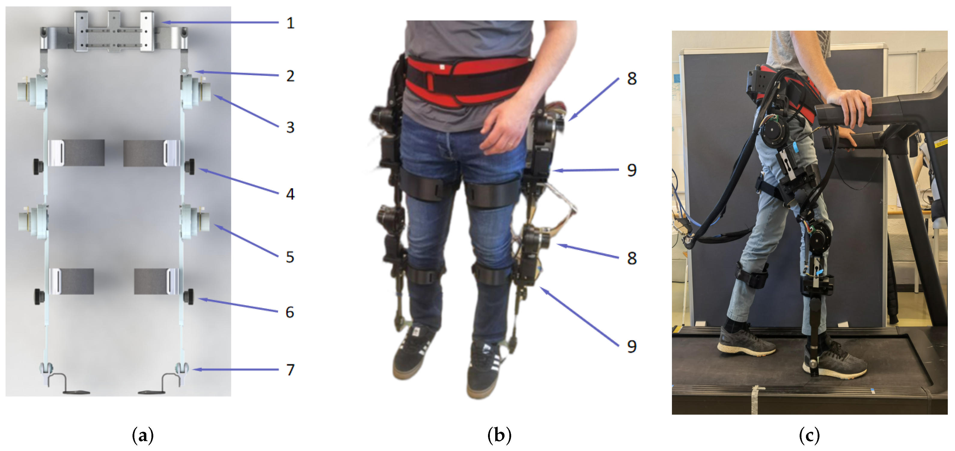
2. Active Lower Limb Exoskeleton Robot

2.1. The ALEXO Concept

The concept of the ALEXO is shown in Figure 1, which was developed on the basis of the lower-limb module of the full-body exoskeleton AXO-SUIT [37,38].
The ALEXO was designed to help individuals with walking difficulty by enhancing the lower limbs’ motion in the sagittal plane. The ALEXO exoskeleton has a total of 8 DOFs. The hip joint of the ALEXO has two DOFs: one active DOF in the sagittal plane to provide external active assistive torque, and a passive DOF for adduction and abduction. The knee joint has one active DOF for flexion and extension. The ankle joint is passive to accommodate dorsiflexion and plantar flexion.
The exoskeleton is adaptable to different body sizes and can adjust shank length, thigh length, and hip width, and interchange the user attachment option depending on user needs. Furthermore, adjustable mechanical end-stops are used in the system to ensure user safety. The ranges of motion of the joint angles are shown in Table 1, which is sufficient to accommodate the human motion.

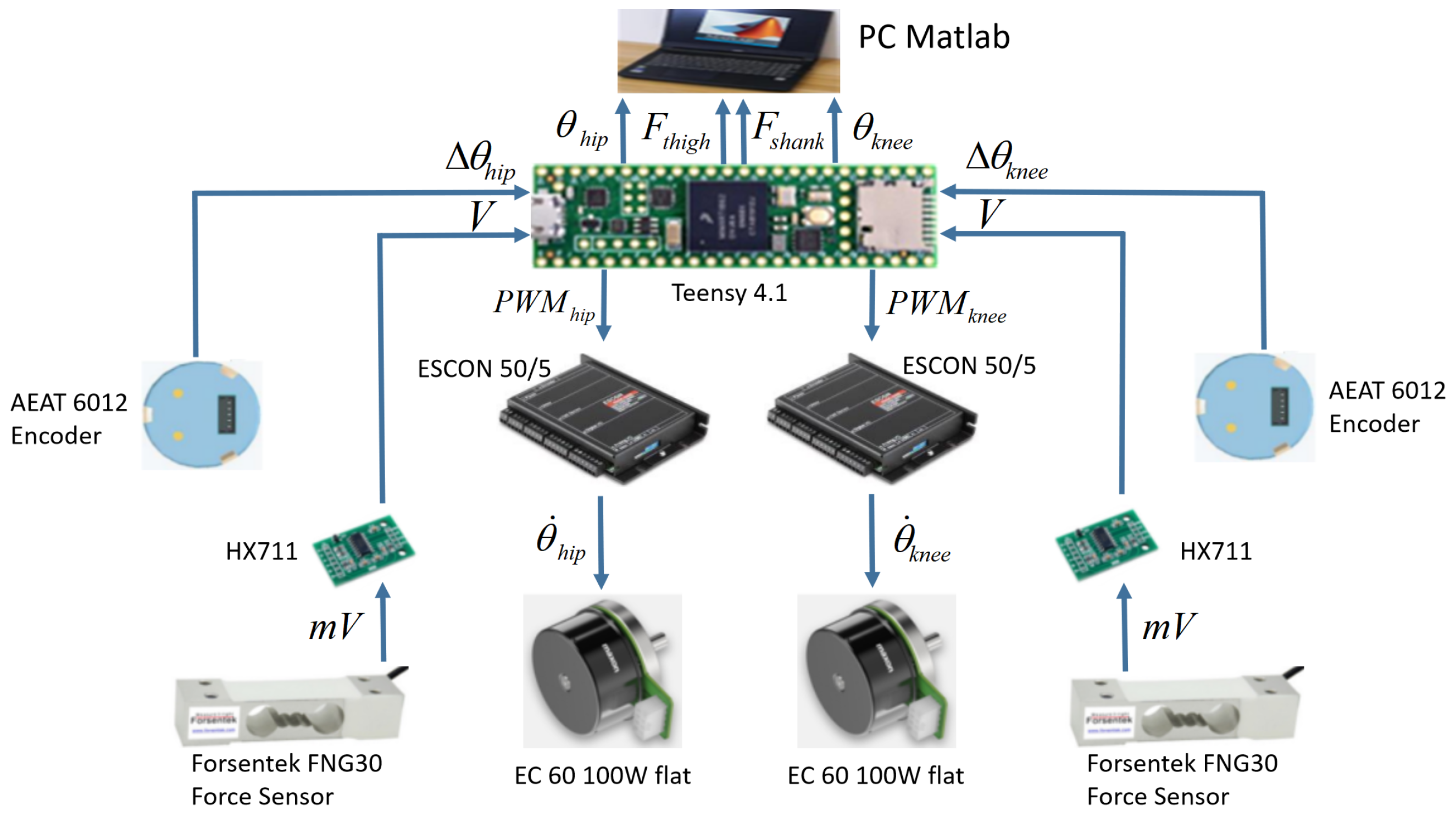
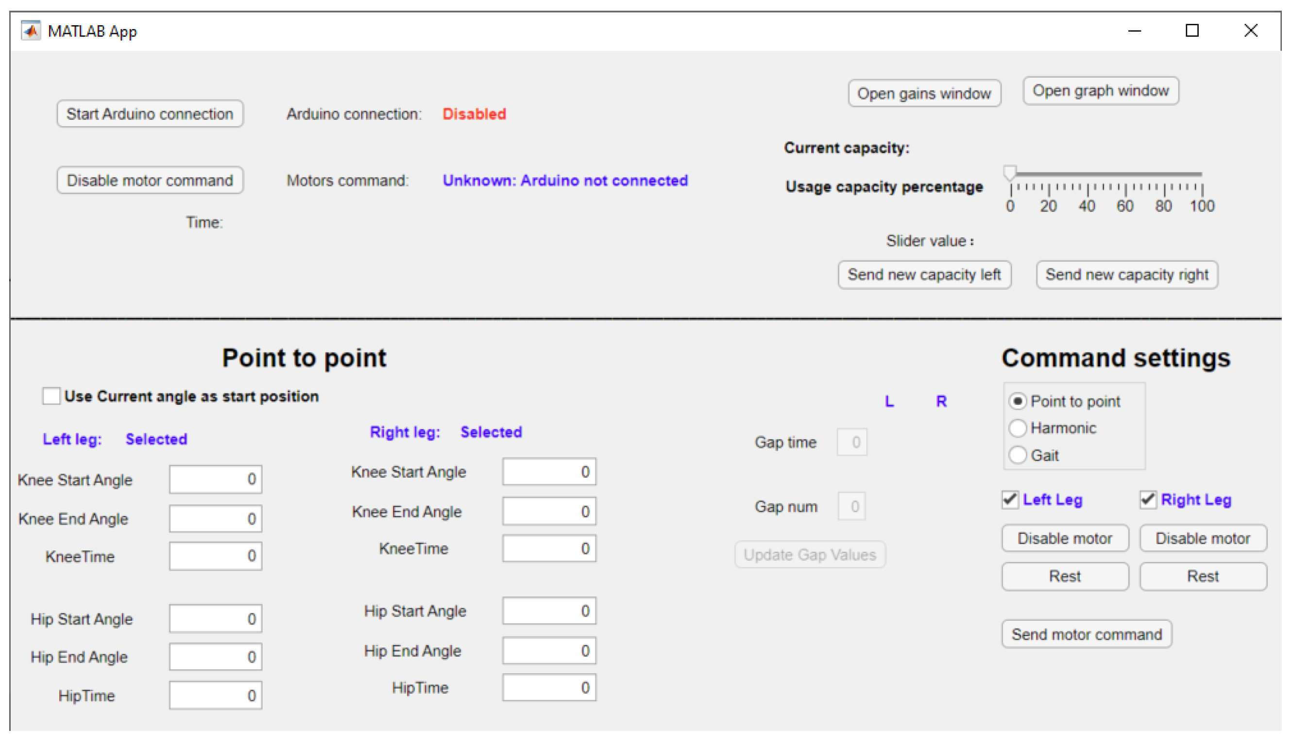
2.2. Hardware and Control Architecture

The mechanical structures of ALEXO are made of 6061 and 7075 aluminum alloy. The light-weighted segments reduce the system’s inertia. Four 3D-printed TPA cuffs are attached to the thigh part and the shank part of both legs, to fixate and align the human lower limbs with their counterparts of the exoskeleton. Each cuff consists of two curved segments, one in the front and one in the back, and it is connected to an adjustable slide rail to adjust for different thigh and shank sizes. Elastic straps are used to tighten the cuffs. ALEXO has two glass fiber foot insoles, which fit into users’ shoes. Four Maxon EC60 48V 100W flat motors are selected for hip and knee joints. The motor’s drive integrates back-driveable harmonic gear drives with a ratio of 1:120 for the hip and 1:50 for the knee joint, respectively.
The sensing and control architectures of ALEXO are illustrated in Figure 2. The system consists of two Teensy 4.1 micro-controller boards that are serially connected to a PC. Each Teensy is connected to a leg and processes data from its hip and knee joint. In particular, each Teensy is connected to two ESCON 50/5 servo controllers, two Broadcom AEAT 6012 absolute encoders, and two HX711 load cell amplifiers. The Broadcom encoders are placed on the non-drive side of ALEXO and read the joint angle of the hip and knee directly from the exoskeleton.
ALEXO is operated on hierarchical control. The high-level control is implemented on the Teensy 4.1 micro-controllers. A computer connected serially to each Teensy has a user interface, in which data are received and monitored in real-time. By having high-speed serial data communication (5 ms cycle time) between the ESCON controller and sensors, the Teensy boards can compute reference trajectories and send these to the low-level ESCON 50/5 servo controller.

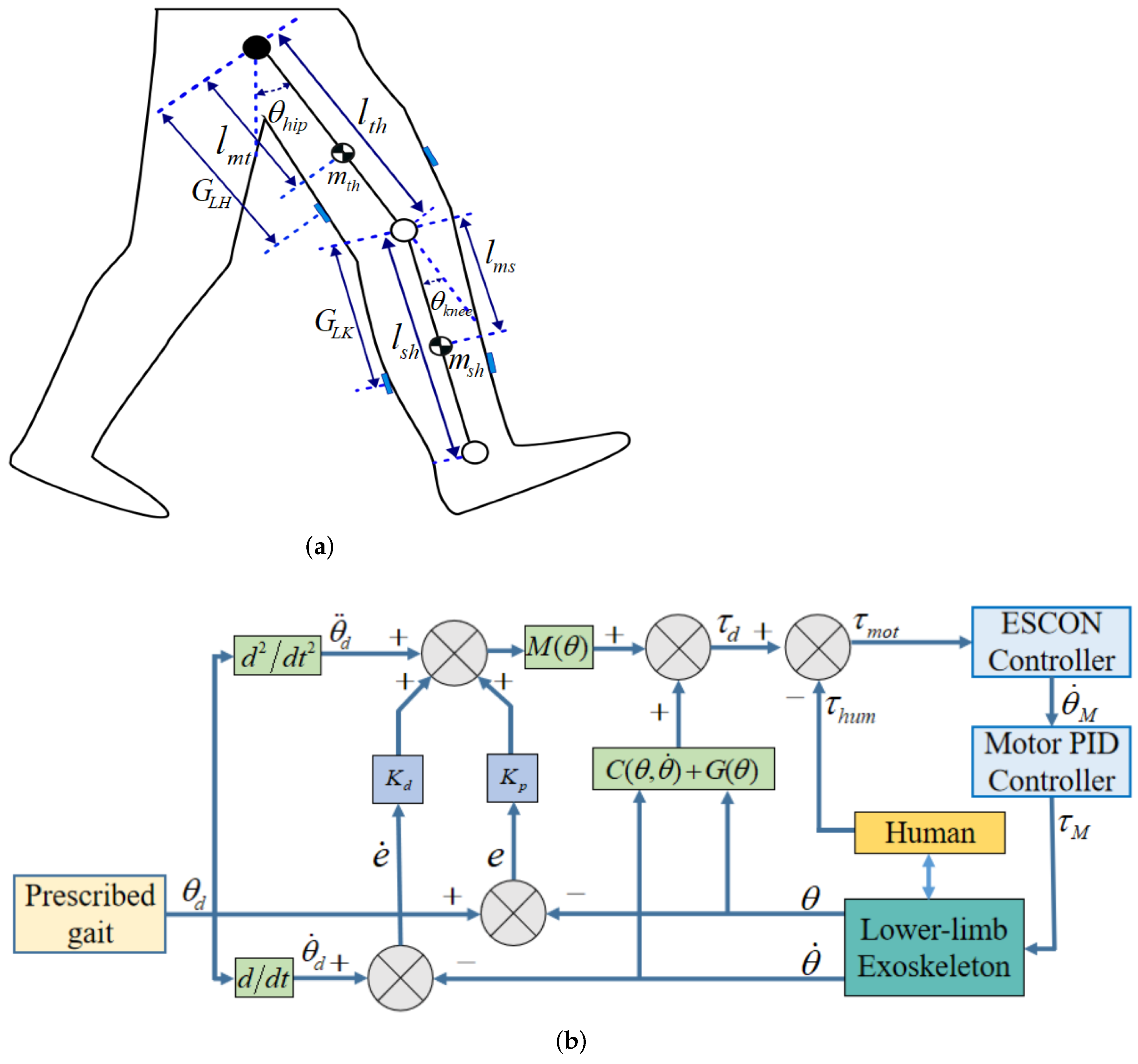
3. Trajectory Control Method
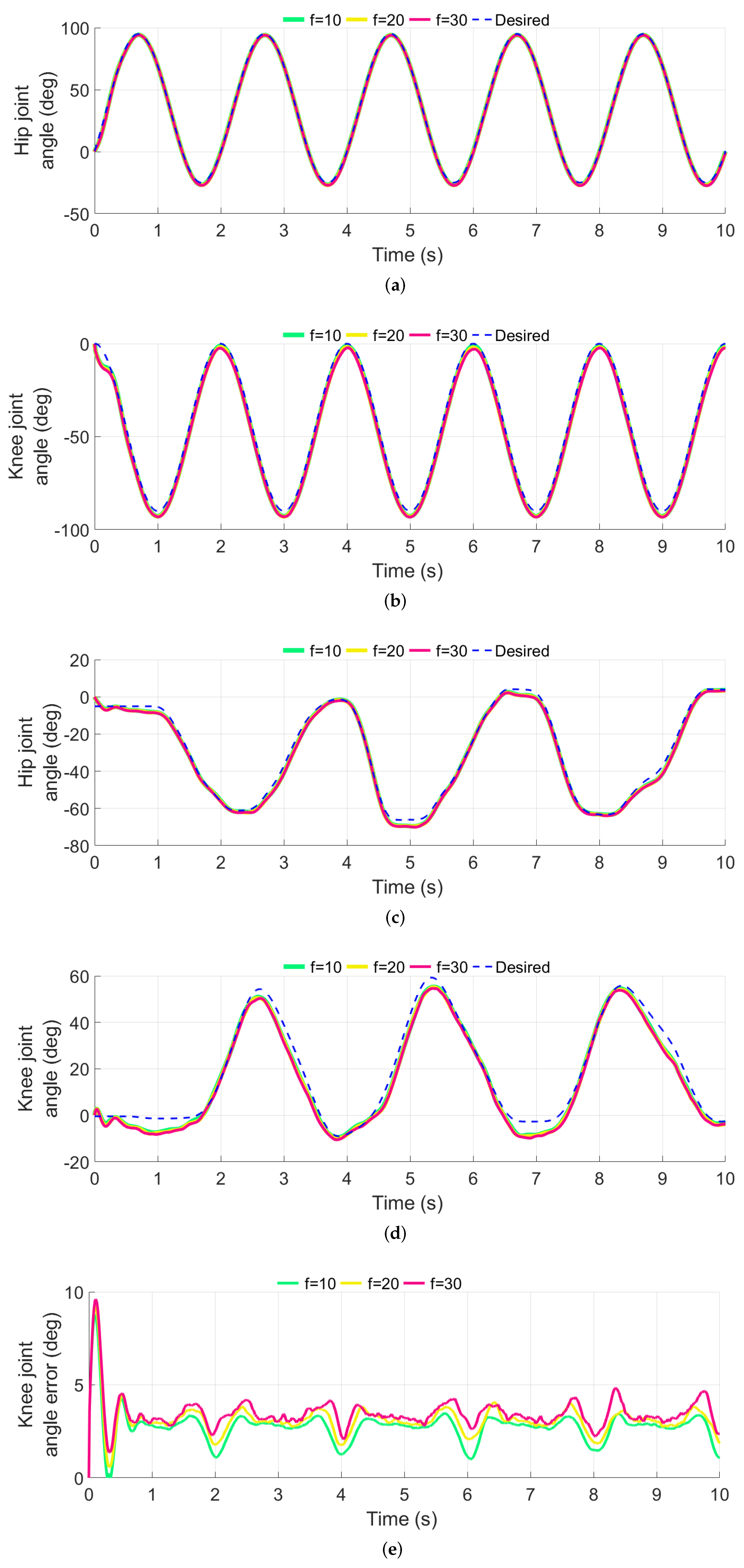
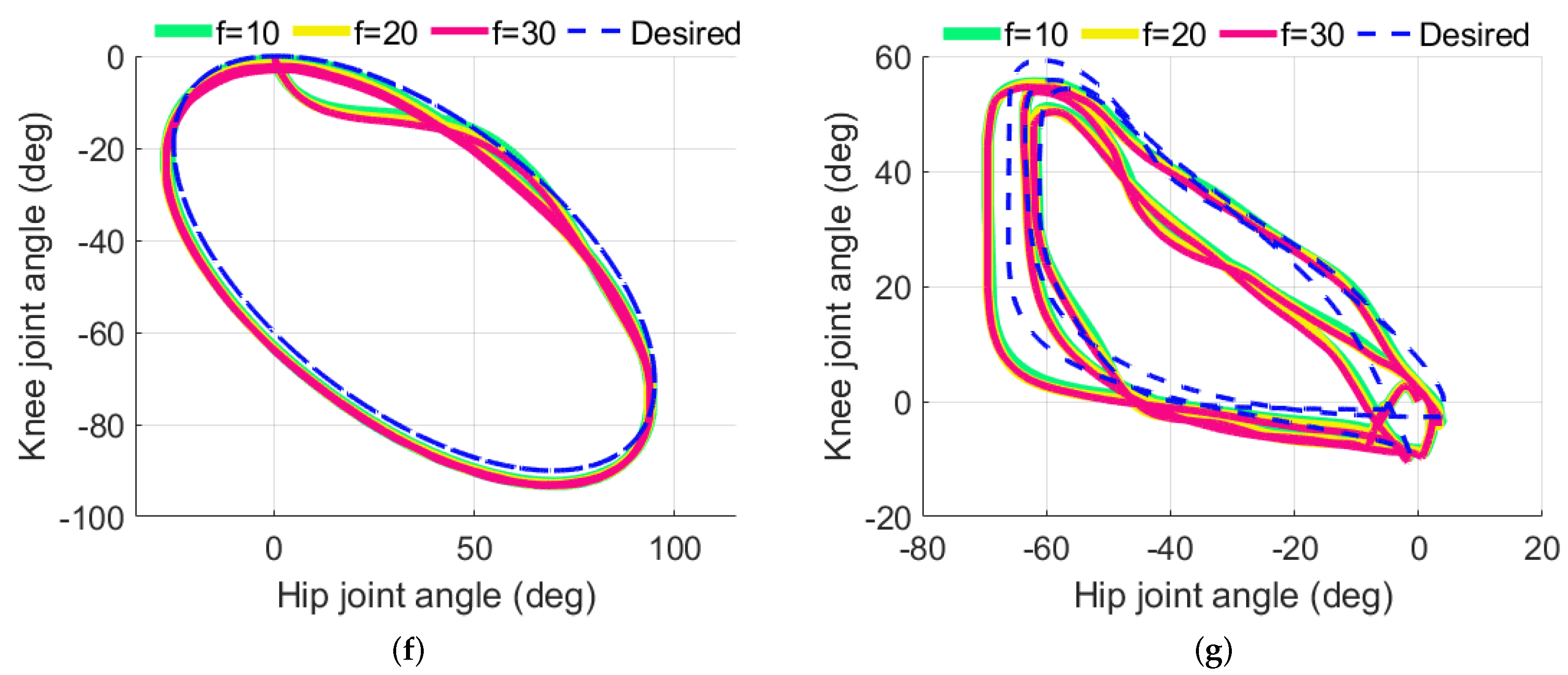
As the leg segments of the ALEXO follow the human lower limb motion with 2-DOF active, the robot movement can be described as a two-link system. Thus the computed torque control method can be adopted to calculate the motor torque through the exoskeleton dynamic analysis. Figure 3 illustrates the ALEXO exoskeleton dynamic model.
The nonlinear dynamics of the ALEXO exoskeleton interacting with the user is given as:
M ( θ ) θ ¨ + C ( θ ˙ , θ ) θ ˙ + G ( θ ) = τ m o t + τ h u m
where M ( θ ) is the inertial matrix; C ( θ ˙ , θ ) represents the matrix of Coriolis and centrifugal force; G ( θ ) donates the gravitational effect, θ = [ θ h i p θ k n e e ] T , where θ h i p and θ k n e e are the hip joint and the knee joint of the exoskeleton, respectively (see specific equations in Appendix A); and τ m o t and τ h u m are torques from the exoskeleton and the human joint, respectively.
As shown in Figure 3, the trajectory tracking error can be written as:
e ( t ) = θ d ( t ) θ ( t )
where θ d ( t ) = [ θ d , h , θ d , k ] T are predefined trajectories of hip and knee joints; e is the difference between desired and actual angles. Considering Equations (1) and (2), we have:
θ ¨ = M 1 ( τ m o t + τ h u m C ( θ ˙ , θ ) θ ˙ G ( θ ) )
e ¨ = θ ¨ d θ ¨
Equation (4) can be written as
e ¨ = θ ¨ d M 1 ( τ m o t + τ h u m C ( θ ˙ , θ ) θ ˙ G ( θ ) )
The control input is set as u = e ¨ , then Equation (5) can be rewritten as
τ m o t + τ h u m = M ( θ ¨ d u ) + C ( θ ˙ , θ ) θ ˙ + G ( θ )
By adopting proportional-differential (PD) feedback control, u is expressed as
u = K p e K d e ˙
Thus, Equation (6) can be written as
τ m o t + τ h u m = M ( θ ¨ d + K p e + K d e ˙ ) + C ( θ ˙ , θ ) θ ˙ + G ( θ )
where K p and K d are the proportional and the derivative gains of the CTC controller.
The human joint torque τ h u m = [ τ h u m H , τ h u m K ] T can be calculated as:
τ h u m H =   ( m t h l m t 2 + 1 12 m t h l t h 2 + m s h ( 2 l t h l m s cos θ k n e e + l t h 2 +   l m s 2 ) + 1 12 m s h l s h 2 ) θ ¨ h i p ( m s h ( l m s 2 + l t h l m s cos θ k n e e ) +   1 12 m s h l s h 2 ) θ ¨ k n e e + m s h l t h l m s sin θ k n e e ( 2 θ ˙ k n e e θ ˙ h i p ) +   m s h l t h l m s sin θ k n e e ( θ ˙ k n e e 2 ) + m t h g l m t sin θ h i p +   m s h g ( l t h sin θ h i p + l m s sin ( θ h i p θ k n e e ) )   F s h ( G L H + G L K ) F s k l t h cos θ k n e e
τ h u m K = ( m s h ( l m s 2 + l t h l m s cos θ k n e e ) + 1 12 m s h l s h 2 ) θ ¨ h i p + ( m s h l m s 2 + 1 12 m s h l s h 2 ) θ ¨ k n e e + m s h l t h l m s sin θ k n e e ( θ ˙ h i p 2 ) +   m s h g l m s sin ( θ h i p θ k n e e ) F s k G L K
where F s h and F s k are the interaction forces from the load sensors on the thigh and the shank; G L H and G L K are the lengths from the hip and the knee joint to the load sensors on the thigh and the shank. l t h is the length of the ALEXO thigh segment, and l s h is the shank length; l m t is the distance from the centroid of the thigh segment to the hip joint, and l m s is the distance from the centroid of the shank segment to the knee joint; m t h and m s h are the mass of the thigh and the shank, respectively.
ESCON controllers adopt velocity control for motors. It is known that
θ ˙ M = K s V K s t τ m o t
where θ ˙ M is the motor speed. V is the operating voltage of the motor. K s is the speed constant of the motor and K s t is an equivalent torque constant of the motor. As the exoskeleton joints adopt harmonic drives, the output velocity from the motor θ ˙ M ( t ) can be expressed as:
θ ˙ M = 1 K g r ( K s V K s t τ m o t )
where K g r is the speed ratio of the harmonic drives, and τ m o t is the computed torque as the reference input for the ESCON controller, which regulates the motor to generate the driving torque τ M .

4. Simulations

Simulations are conducted on MATLAB with the developed control method. For simulating the interaction forces, two forces, F t and F s , that are applied on the thigh and shank, are expressed as:
F t = 50 cos ( ω t ) 50 + f t
F s = 40 cos ( ω t ) 40 + f s
where ω is set to π , and f t and f s are random disturbances ranging from 0 to 10 N. Considering the Ziegler–Nichols method [39], K p and K d can be obtained:
K p = 0.6 K u
K d = 3 K u T o c 40
where K u is the gain to achieve a stable oscillation, and T o c is the oscillation period. The mass distribution of the ALEXO and the controller gains are shown in Table 2.
The reference trajectories of the hip joint and the knee joint are given in the form of harmonic functions as:
θ h = 60 sin ( 3.14 t 0.609 ) + 35
θ k = 45 cos ( 3.14 t ) 45
The results of trajectory tracking are shown in Figure 4. The average errors with sinusoidal trajectories of the trajectory tracking for the hip and knee joints are 0.972 and 2.750 degrees, respectively. With the real trajectories, the average errors are 1.767 and 3.105 degrees on the hip and knee joints, respectively.
In another simulation, the random disturbance forces are set at two other levels, ranging from 0 to 20 N and 0 to 30 N, respectively. The results are shown in Figure 5. With the increased disturbance forces, the average errors of the hip joint increased to 1.147 and 1.315 degrees using the sinusoidal trajectories, respectively, while the average errors of the knee joint are found to be 3.124 and 3.469 degrees. By using the real gait, the average errors of the hip and knee joints are 1.937 and 3.407 degrees with 20 N disturbance forces on the joints, respectively. As for 30 N disturbance forces, tthe average errors are found to be 2.122 and 3.745 degrees on the hip and knee joints, respectively.

5. Physical Experiments

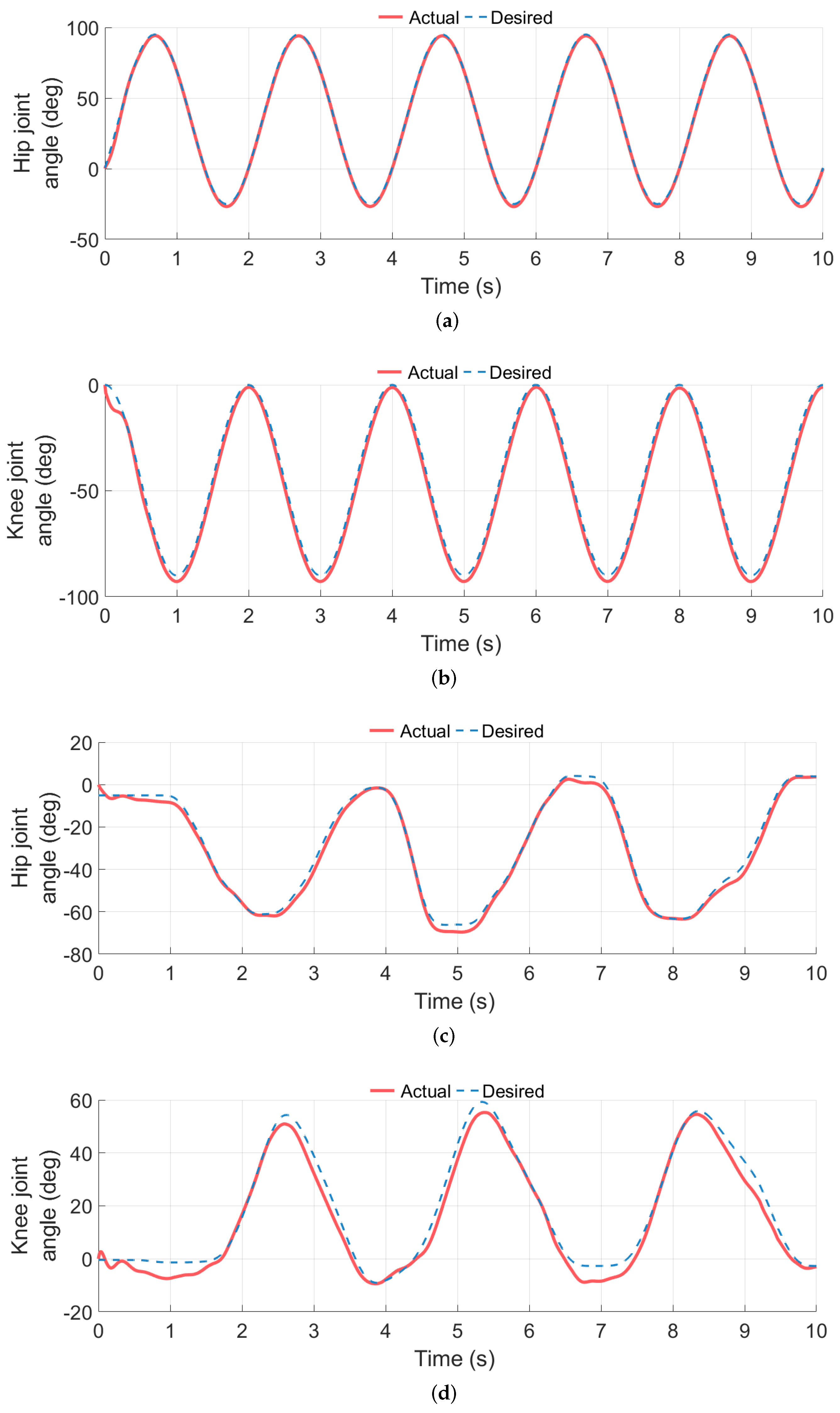
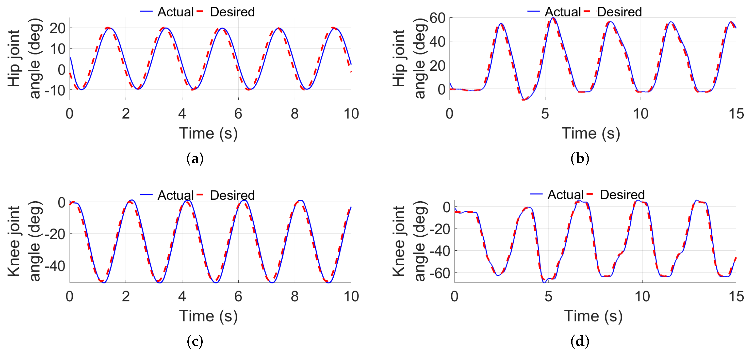
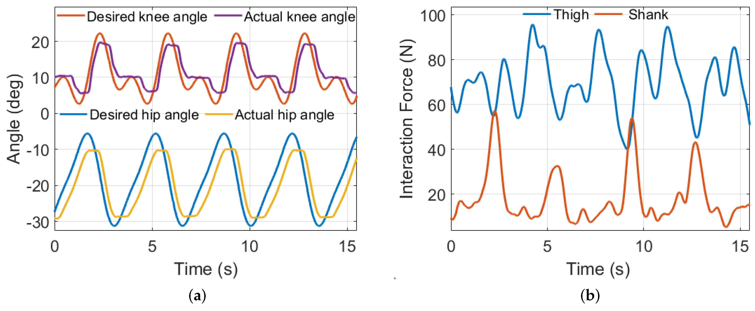
5.1. Trajectory Tracking

The control algorithm was first tested on the ALEXO without users. The exoskeleton was fixed on the aluminum alloy frame, and sinusoidal trajectories were applied to the hip and the knee joints:
θ d h = 15 sin ( ω t ) , θ d k = 25 sin ( ω t ) + 25
The results of the sinusoidal trajectory tracking are shown in Figure 6. Larger errors are shown at the beginning of the trajectory while smaller errors appear during the trajectory tracking mode, but the level of errors is generally acceptable.
A real walking gait trajectory was also used to test the performance of the trajectory tracking controller. The trajectory is obtained by putting the exoskeleton leg on the human subject and collecting joint sensor data in transparent mode. The results are shown in Figure 6b,d, respectively. Although there are some errors on the knee joint, the whole exoskeleton robot had a good performance on trajectory tracking to realize the walking gait.

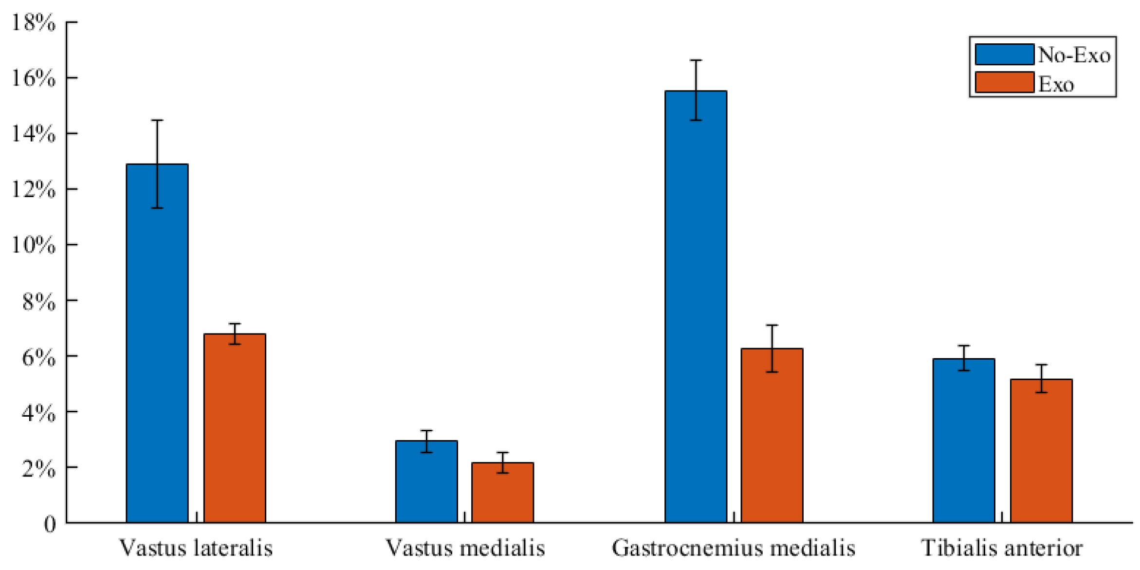
5.2. Walking Assistance Tests

The proposed method was evaluated on walking assistance with the ALEXO exoskeleton. The control program was written in C language, and a user interface was developed in MATLAB APP Designer, as shown in Figure 7. The GUI controls communication to Teensy 4.1 and collects data from the serial port. The “Point to Point” mode can achieve moving the leg to a fixed position. The “Harmonic” mode can test the continuous movement performance of the exoskeleton. By switching to the “Gait” mode, the “command settings” function can record the subject’s movement through the encoder, and provide the recorded gait to the controller as the reference.
Experiments were performed on a single subject with a height of 179 cm and weight of 65 kg. The subject was required to walk on the treadmill wearing the ALEXO, which was working on the trajectory tracking mode (Figure 1c). The interaction force between the exoskeleton and the human body was collected during walking.
As shown in Figure 8, the exoskeleton follows the desired trajectory, while providing assistive force to the subject. Periodical force patterns can be observed during the gait cycle on the thigh and the shank segments. Maximum interaction forces of 95.83 N and 57.29 N were measured at the thigh and the shank, respectively.
In the experiments, EMG signals are collected to measure the muscle activities during walking with and without the exoskeleton, respectively. EMG signals of the lower limb muscle groups—the vastus lateralis (VL), the vastus medialis (VM), the gastrocnemius medialis (GM) and the tibialis anterior (TA)—were collected and normalized, with respect to the maximal voluntary contraction (MVC), and the mean amplitude value of the EMG signal was computed as a percentage of the MVC.
The results are shown in Figure 9. Without the exoskeleton, the mean amplitude values (% of MVC) of the EMG were found to be 6.45 ± 0.787, 1.86 ± 0.191, 7.76 ± 0.538, and 2.95 ± 0.224 on the VL, VM, GM, and TA, respectively. The muscle activities were found to be 3.40 ± 0.176, 1.08 ± 0.184, 3.13 ± 0.428, and 2.60 ± 0.261 with the exoskeleton. The probability values are 6.68 × 10 4 , 2.68 × 10 1 , 4.60 × 10 3 , and 2.95 × 10 2 , respectively. Significant differences were found in the VL, GM, and TA between conditions (with or without exoskeleton) in the comparisons. The results show significant decreases of efforts.

6. Discussion

In this paper, a computed torque control method is proposed to control a novel active lower-limb exoskeleton to assist a person with walking difficulties with walking. Compared to the control methods in [17,30], the proposed CTC method is more simple and reliable to implement. The proposed CTC controller can generate the motor torque while considering the interaction forces. The users’ natural gait is adopted as the reference gait and human joint torque is calculated to generate additional torque for assistance, in which the interaction forces can adjust the output torque of the proposed CTC controller through physical human–robot interaction. The trajectory tracking ability has been verified by increasing the disturbance force level. While increasing the disturbance forces from 10 N to 30 N, the errors are found to increase very slightly from 0.972 and 2.750 to 1.315 and 3.469 degrees on the hip and knee joints with the sinusoidal trajectory, respectively. Similar results are also found by using the real gait trajectory. The position errors of the knee joint are larger than the errors of the hip joint, which indicates that the knee joint is more sensitive to the disturbance.
With less system complexity, the trajectory tracking simulation results show the proposed control method has a similar tracking performance as the method in [17]. Furthermore, the muscle activities results showed that the exoskeleton can bring more assistance than the exoskeleton in [30].
It is noted that, in this work, we did not measure the ground reaction force. As a matter of fact, the ground reaction force can be obtained by different approaches; for example, either by a treadmill with load sensors [40], or by pressure sensors embedded directly in the exoskeleton foot [41]. Considering the hardware reliability and real time application [42,43], the ALEXO adopts the interaction force sensor instead of measuring the ground reaction force for gait control. The interaction forces are considered to encompass the influence of the ground reaction forces.
It has to be noted that the proposed control method brings more assistance to the shank, where the EMG signal from the gastrocnemius has a larger decrease than the signal from the vastus. Considering the exoskeleton configuration [44], the EMG signal of the soleus muscle is hard to collect due to the exoskeleton cuffs, which makes the associate region of skin not accessible. Thus, the other four muscles’ EMG signals are collected. The statistical significance differences of the lower limb indicate that the VL muscle shows more obvious assistance, while the VM muscle did not have obvious differences. The results of the GM and the TA muscles show a larger significant difference than the VM muscle, which means the shank received more assistance than the thigh during the movement. We noted that, in an early trial of the ALEXO, increased muscle activities were observed with a gait control using a classic PID position control. It is, thus, evidenced that the proposed controller can provide effective assistance during walking. On the other hand, this method could be improved by developing an adaptive gait generator to generate an adjustable reference gait for optimal exoskeleton assistance. Moreover, using wearable sensor devices, such as sensor bands [45], could achieve online parameter adjustment of the adaptive gait generator.

7. Conclusions

This paper presents the design of an active lower limb exoskeleton (ALEXO) for walking assistance. A trajectory tracking control method is proposed, which has been simulated and tested physically. The results of the EMG signals show significant reduction in muscle activities during walking with the exoskeleton, which demonstrated that the ALEXO was able to provide sufficient assistance on the hip and knee joints during walking to follow a given gait.
Future work will focus on improving the control method to achieve adaptive gait control for different users. The effectiveness of the ALEXO in assisting individuals with different walking patterns will be evaluated through user studies. Furthermore, the movement primitives theory will be applied to the ALEXO, which can contribute to achieving gait control that is more robust and intelligent.

Author Contributions

Conceptualization, L.Y., H.L. and S.B.; methodology, L.Y., H.L. and S.B.; software, L.Y.; validation, L.Y.; formal analysis, L.Y.; investigation, L.Y.; writing—original draft preparation, L.Y.; writing—review and editing, L.Y. and S.B.; supervision, L.Y. and S.B. All authors have read and agreed to the published version of the manuscript.

Funding

This research was funded by Frode V.Nyegaards and Wife’s fund for the ALEXO project.

Data Availability Statement

All data relevant for this study is provided in the manuscript.

Acknowledgments

L. Yu acknowledges financial support from Chinese Scholarship for his study at Aalborg University, Aalborg, Denmark; A. d’Elbreil is acknowledged for his contribution in software development.

Conflicts of Interest

The authors declare no conflict of interest.

Appendix A

The specific expressions of M ( θ ) , C ( θ ˙ , θ ) and G ( θ ) in Equation (1) are given as:
M ( θ ) = M 11 M 12 M 21 M 22 , G ( θ ) = G 11 G 21 C ( θ ˙ , θ ) = C 11 C 12 C 21 C 22
M 11 = m t h l m t 2 + 1 12 m t h l t h 2 + m s h ( l t h 2 + l m s 2 + 2 l t h l m s cos ( θ k n e e ) ) + 1 12 m s h l s h 2
M 12 = M 21 = m s h ( l m s 2 + l t h l m s cos ( θ k n e e ) ) 1 12 m s h l s h 2
M 22 = m s h l m s 2 + 1 12 m s h l s h 2
C 11 = m s h l t h l m s · sin ( θ k n e e ) · ( 2 θ ˙ k n e e )
C 12 = m s h l t h l m s · sin ( θ k n e e ) · ( θ ˙ k n e e )
C 21 = m s h l t h l m s · sin ( θ k n e e ) · ( θ ˙ h i p )
C 22 = 0
G 11 = ( m t h l m t + m s h l t h ) · g · sin ( θ h i p ) + m s h · g · l m s · sin ( θ h i p θ k n e e )
G 21 = m s h · g · l m s · sin ( θ h i p θ k n e e )

References

  1. Nam, K.Y.; Kim, H.J.; Kwon, B.S.; Park, J.; Lee, H.J.; Yoo, A. Robot-assisted gait training (Lokomat) improves walking function and activity in people with spinal cord injury: A systematic review. J. Neuroeng. Rehabil. 2017, 14, 24. [Google Scholar] [CrossRef] [PubMed]
  2. Tu, Y.; Zhu, A.; Song, J.; Zhang, X.; Cao, G. Design and experimental evaluation of a lower-limb exoskeleton for assisting workers with motorized tuning of squat heights. IEEE Trans. Neural Syst. Rehabil. Eng. 2022, 30, 184–193. [Google Scholar] [CrossRef] [PubMed]
  3. Husty, M.; Birlescu, I.; Tucan, P.; Vaida, C.; Pisla, D. An algebraic parameterization approach for parallel robots analysis. Mech. Mach. Theory 2019, 140, 245–257. [Google Scholar] [CrossRef]
  4. Grazi, L.; Trigili, E.; Proface, G.; Giovacchini, F.; Crea, S.; Vitiello, N. Design and experimental evaluation of a semi-passive upper-limb exoskeleton for workers with motorized tuning of assistance. IEEE Trans. Neural Syst. Rehabil. Eng. 2020, 28, 2276–2285. [Google Scholar] [CrossRef]
  5. Bai, S.; Virk, G.; Sugar, T. Wearable Exoskeleton Systems: Design, Control and Applications; Institution of Engineering and Technology: London, UK, 2018. [Google Scholar] [CrossRef]
  6. Von Glinski, A.; Yilmaz, E.; Mrotzek, S.; Marek, E.; Jettkant, B.; Brinkemper, A.; Fisahn, C.; Schildhauer, T.A.; Geßmann, J. Effectiveness of an on-body lifting aid (HAL® for care support) to reduce lower back muscle activity during repetitive lifting tasks. J. Clin. Neurosci. 2019, 63, 249–255. [Google Scholar] [CrossRef] [PubMed]
  7. Zhang, G.; Wang, J.; Yang, P.; Guo, S. A learning control scheme for upper-limb exoskeleton via adaptive sliding mode technique. Mechatronics 2022, 86, 102832. [Google Scholar] [CrossRef]
  8. Liu, J.; Zhang, Y.; Wang, J.; Chen, W. Adaptive sliding mode control for a lower-limb exoskeleton rehabilitation robot. In Proceedings of the 2018 13th IEEE Conference on Industrial Electronics and Applications (ICIEA), Wuhan, China, 31 May 2018–2 June 2018; pp. 1481–1486. [Google Scholar] [CrossRef]
  9. Meijneke, C.; van Oort, G.; Sluiter, V.; van Asseldonk, E.; Tagliamonte, N.L.; Tamburella, F.; Pisotta, I.; Masciullo, M.; Arquilla, M.; Molinari, M.; et al. Symbitron exoskeleton: Design, control, and evaluation of a modular exoskeleton for incomplete and complete spinal cord injured individuals. IEEE Trans. Neural Syst. Rehabil. Eng. 2021, 29, 330–339. [Google Scholar] [CrossRef] [PubMed]
  10. Tamantini, C.; Cordella, F.; Lauretti, C.; Di Luzio, F.S.; Campagnola, B.; Cricenti, L.; Bravi, M.; Bressi, F.; Draicchio, F.; Sterzi, S.; et al. Tailoring upper-limb robot-aided orthopedic rehabilitation on patients’ psychophysiological state. IEEE Trans. Neural Syst. Rehabil. Eng. 2023, 31, 3297–3306. [Google Scholar] [CrossRef]
  11. Zhang, L.; Guo, S.; Sun, Q. Development and assist-as-needed control of an end-effector upper limb rehabilitation robot. Appl. Sci. 2020, 10, 6684. [Google Scholar] [CrossRef]
  12. Islam, M.R.; Assad-Uz-Zaman, M.; Al Zubayer Swapnil, A.; Ahmed, T.; Rahman, M.H. An ergonomic shoulder for robot-aided rehabilitation with hybrid control. Microsyst. Technol. 2021, 27, 159–172. [Google Scholar] [CrossRef]
  13. Cai, H.; Guo, S.; Yang, Z.; Guo, J. A motor recovery training and evaluation method for the upper limb rehabilitation robotic system. IEEE Sens. J. 2023, 23, 9871–9879. [Google Scholar] [CrossRef]
  14. Wang, X.; Guo, S.; Song, M.; Wang, P. Mechanical design and experimental verification of a parallel hip exoskeleton with virtual rotation center. In Proceedings of the 2021 6th IEEE International Conference on Advanced Robotics and Mechatronics (ICARM), Chongqing, China, 3–5 July 2021; pp. 230–235. [Google Scholar] [CrossRef]
  15. Zhou, X.; Yu, Z.; Wang, M.; Chen, D.; Ye, X. Design of control system for lower limb exoskeleton robot. In Proceedings of the 2022 8th International Conference on Control, Automation and Robotics (ICCAR), Xiamen, China, 8–10 April 2022; pp. 122–126. [Google Scholar] [CrossRef]
  16. Peng, X.; Acosta-Sojo, Y.; Wu, M.I.; Stirling, L. Actuation timing perception of a powered ankle exoskeleton and its associated ankle angle changes during walking. IEEE Trans. Neural Syst. Rehabil. Eng. 2022, 30, 869–877. [Google Scholar] [CrossRef]
  17. Han, S.; Wang, H.; Tian, Y. Adaptive computed torque control based on RBF network for a lower limb exoskeleton. In Proceedings of the 2018 IEEE 15th International Workshop on Advanced Motion Control (AMC), Tokyo, Japan, 9–11 March 2018; pp. 35–40. [Google Scholar] [CrossRef]
  18. Véronneau, C.; Lucking Bigué, J.P.; Lussier-Desbiens, A.; Plante, J.S. A high-bandwidth back-drivable hydrostatic power distribution system for exoskeletons based on magnetorheological clutches. IEEE Robot. Autom. Lett. 2018, 3, 2592–2599. [Google Scholar] [CrossRef]
  19. Galle, S.; Malcolm, P.; Collins, S.H.; De Clercq, D. Reducing the metabolic cost of walking with an ankle exoskeleton: Interaction between actuation timing and power. J. Neuroeng. Rehabil. 2017, 14, 35. [Google Scholar] [CrossRef]
  20. Aach, M.; Schildhauer, T.A.; Zieriacks, A.; Jansen, O.; Weßling, M.; Brinkemper, A.; Grasmücke, D. Feasibility, safety, and functional outcomes using the neurological controlled Hybrid Assistive Limb exoskeleton (HAL®) following acute incomplete and complete spinal cord injury—Results of 50 patients. J. Spinal Cord Med. 2023, 46, 574–581. [Google Scholar] [CrossRef] [PubMed]
  21. Zhu, A.; Tu, Y.; Zheng, W.; Shen, H.; Zhang, X. Adaptive control of man-machine interaction force for lower limb exoskeleton rehabilitation robot. In Proceedings of the 2018 IEEE International Conference on Information and Automation (ICIA), Wuyishan, China, 11–13 August 2018; pp. 740–743. [Google Scholar] [CrossRef]
  22. Gui, K.; Liu, H.; Zhang, D. A generalized framework to achieve coordinated admittance control for multi-joint lower limb robotic exoskeleton. In Proceedings of the 2017 International Conference on Rehabilitation Robotics (ICORR), London, UK, 17–20 July 2017; pp. 228–233. [Google Scholar] [CrossRef]
  23. Wang, S.; Wang, L.; Meijneke, C.; van Asseldonk, E.; Hoellinger, T.; Cheron, G.; Ivanenko, Y.; La Scaleia, V.; Sylos-Labini, F.; Molinari, M.; et al. Design and control of the MINDWALKER exoskeleton. IEEE Trans. Neural Syst. Rehabil. Eng. 2015, 23, 277–286. [Google Scholar] [CrossRef]
  24. Kim, J.; Kim, S.J.; Choi, J. Real-time gait phase detection and estimation of gait speed and ground slope for a robotic knee orthosis. In Proceedings of the 2015 IEEE International Conference on Rehabilitation Robotics (ICORR), Singapore, 11–14 August 2015; pp. 392–397. [Google Scholar] [CrossRef]
  25. Manchola, M.D.S.; Mayag, L.J.A.; Munera, M.; García, C.A.C. Impedance-based backdrivability recovery of a lower-limb exoskeleton for knee rehabilitation. In Proceedings of the 2019 IEEE 4th Colombian Conference on Automatic Control (CCAC), Medellin, Colombia, 15–18 October 2019; pp. 1–6. [Google Scholar] [CrossRef]
  26. Bortole, M.; Venkatakrishnan, A.; Zhu, F.; Moreno, J.C.; Francisco, G.E.; Pons, J.L.; Contreras-Vidal, J.L. The H2 robotic exoskeleton for gait rehabilitation after stroke: Early findings from a clinical study. J. Neuroeng. Rehabil. 2015, 12, 54. [Google Scholar] [CrossRef]
  27. Yeung, L.F.; Ockenfeld, C.; Pang, M.K.; Wai, H.W.; Soo, O.Y.; Li, S.W.; Tong, K.Y. Design of an exoskeleton ankle robot for robot-assisted gait training of stroke patients. In Proceedings of the 2017 International Conference on Rehabilitation Robotics (ICORR), London, UK, 17–20 July 2017; pp. 211–215. [Google Scholar] [CrossRef]
  28. Li, M.; Aoyama, T.; Hasegawa, Y. Gait modification for improving walking stability of exoskeleton assisted paraplegic patient. ROBOMECH J. 2020, 7, 21. [Google Scholar] [CrossRef]
  29. Lee, H.D.; Park, H.; Seongho, B.; Kang, T.H. Development of a soft exosuit system for walking assistance during stair ascent and descent. Int. J. Control. Autom. Syst. 2020, 18, 2678–2686. [Google Scholar] [CrossRef]
  30. Kang, I.; Hsu, H.; Young, A. The effect of hip assistance levels on human energetic cost using robotic hip exoskeletons. IEEE Robot. Autom. Lett. 2019, 4, 430–437. [Google Scholar] [CrossRef]
  31. Koller, J.R.; David Remy, C.; Ferris, D.P. Comparing neural control and mechanically intrinsic control of powered ankle exoskeletons. In Proceedings of the 2017 International Conference on Rehabilitation Robotics (ICORR), London, UK, 17–20 July 2017; pp. 294–299. [Google Scholar] [CrossRef]
  32. Xu, D.; Liu, X.; Wang, Q. Knee exoskeleton assistive torque control based on real-time gait event detection. IEEE Trans. Med. Robot. Bionics 2019, 1, 158–168. [Google Scholar] [CrossRef]
  33. Canete, S.; Wilson, E.B.; Jacobs, D.A. Ankle exoskeleton assistance can affect step regulation during self-paced walking. IEEE Trans. Neural Syst. Rehabil. Eng. 2023, 31, 474–483. [Google Scholar] [CrossRef] [PubMed]
  34. Aljuboury, A.S.; Hameed, A.H.; Ajel, A.R.; Humaidi, A.J.; Alkhayyat, A.; Mhdawi, A.K.A. Robust adaptive control of knee exoskeleton-assistant system based on nonlinear disturbance observer. Actuators 2022, 11, 78. [Google Scholar] [CrossRef]
  35. Narayan, J.; Dwivedy, S.K. Robust LQR-based neural-fuzzy tracking control for a lower limb exoskeleton system with parametric uncertainties and external disturbances. Appl. Bionics Biomech. 2021, 2021, 5573041. [Google Scholar] [CrossRef] [PubMed]
  36. Yu, L.; Leto, H.; d’Elbreil, A.; Bai, S. Design and gait control of an active lower limb exoskeleton for walking assistance. In New Trends in Medical and Service Robotics; Springer: Cham, Swizerland, 2023; pp. 127–135. [Google Scholar]
  37. Christensen, S.; Rafique, S.; Bai, S. Design of a powered full-body exoskeleton for physical assistance of elderly people. Int. J. Adv. Robot. Syst. 2021, 18, 1–15. [Google Scholar] [CrossRef]
  38. Bai, S.; Islam, M.; Power, V.; OŚullivan, L. User-centered development and performance assessment of a modular full-body exoskeleton (AXO-SUIT). Biomim. Intell. Robot. 2022, 2, 100032. [Google Scholar] [CrossRef]
  39. Al-Waeli, K.H.; Ramli, R.; Haris, S.M.; Zulkoffli, Z.B.; Amiri, M.S. Offline ANN-PID controller tuning on a multi-joints lower limb exoskeleton for gait rehabilitation. IEEE Access 2021, 9, 107360–107374. [Google Scholar] [CrossRef]
  40. Yu, L.; Mei, Q.; Xiang, L.; Liu, W.; Mohamad, N.I.; István, B.; Fernandez, J.; Gu, Y. Principal component analysis of the running ground reaction forces with different speeds. Front. Bioeng. Biotechnol. 2021, 9, 629809. [Google Scholar] [CrossRef]
  41. Divekar, N.V.; Lin, J.; Nesler, C.; Borboa, S.; Gregg, R.D. A potential energy shaping controller with ground reaction force feedback for a multi-activity knee-ankle exoskeleton. In Proceedings of the 2020 8th IEEE RAS/EMBS International Conference for Biomedical Robotics and Biomechatronics (BioRob), New York, NY, USA, 29 November 2020–1 December 2020; pp. 997–1003. [Google Scholar] [CrossRef]
  42. Amiri, M.S.; Ramli, R.; Ibrahim, M.F. Initialized model reference adaptive control for lower limb exoskeleton. IEEE Access 2019, 7, 167210–167220. [Google Scholar] [CrossRef]
  43. Nasiri, R.; Shushtari, M.; Arami, A. An adaptive assistance controller to optimize the exoskeleton contribution in rehabilitation. Robotics 2021, 10, 95. [Google Scholar] [CrossRef]
  44. Durandau, G.; Rampeltshammer, W.F.; Kooij, H.v.d.; Sartori, M. Neuromechanical model-based adaptive control of bilateral ankle exoskeletons: Biological joint torque and electromyogram reduction across walking conditions. IEEE Trans. Robot. 2022, 38, 1380–1394. [Google Scholar] [CrossRef]
  45. Wang, X.; Yu, H.; Kold, S.; Rahbek, O.; Bai, S. Wearable sensors for activity monitoring and motion control: A review. Biomim. Intell. Robot. 2023, 3, 100089. [Google Scholar] [CrossRef]
Figure 1. Concept of ALEXO. (a) The CAD model, (b) the physical system, (c) a walking test on treadmill. The system includes: 1. waist support, 2. passive adduction/abduction hip joint, 3. active flexion/extension hip joint, 4. thigh adjustment screw, 5. active flexion/extension knee joint, 6. shank adjustment screw, 7. passive plantar flexion/dorsiflexion ankle joint, 8. motors, 9. Forsentek FNG30 load sensors.
Machines 11 00864 g001
Figure 2. The hardware and control architecture of a single leg in ALEXO.
Machines 11 00864 g002
Figure 3. (a) ALEXO exoskeleton dynamic model. (b) The control scheme of the ALEXO.
Machines 11 00864 g003
Figure 4. Trajectory tracking simulation results: (a) hip joint with sinusoidal trajectory, (b) knee joint with sinusoidal trajectory, (c) hip joint with real gait, (d) knee joint with real gait.
Machines 11 00864 g004
Figure 5. Trajectory tracking simulation with different levels of disturbance forces: (a) hip joint with sinusoidal trajectory, (b) knee joint with sinusoidal trajectory, (c) hip joint with real gait, (d) knee joint with real gait, (e) sinusoidal trajectory error of the knee joint with different levels of disturbance forces, (f) coordination pattern of the hip and the knee joints with sinusoidal trajectory, (g) coordination pattern of the hip and the knee joints with real gait.
Machines 11 00864 g005aMachines 11 00864 g005b
Figure 6. Trajectory tracking results with the physical system: (a) hip joint with sinusoidal trajectory, (b) hip joint with real gait, (c) knee joint with sinusoidal trajectory, (d) knee joint with real gait.
Machines 11 00864 g006
Figure 7. User interface of the ALEXO control.
Machines 11 00864 g007
Figure 8. Human-exoskeleton interaction test with real walking gait trajectory. (a) Angles of hip and knee joints. (b) Interaction force of the lower limb.
Machines 11 00864 g008
Figure 9. Mean muscle activities during walking with and without the exoskeleton.
Machines 11 00864 g009
Table 1. The angular range of motion (ROM) and DOF of joints.
JointMovementActuation TypeROM
HipFlexion/ExtensionActive 30 / 100
-Adduction/AbductionPassive 10 / 15
KneeFlexion/ExtensionActive 0 / 120
AnkleDorsiflexion/Plantar FlexionPassive 20 / 45
Table 2. Mass and control parameters.
DescriptionThigh/Shank
m t h / m s h Mass of the segment (kg) 3.3 / 1.1
l t h / l s h Length of the segment (m) 0.475 / 0.45
l m t / l m s Centroid distance of the segment (m) 0.36 / 0.15
HipKnee
K p 36006400
K d 110140
G L 0.180.175
Disclaimer/Publisher’s Note: The statements, opinions and data contained in all publications are solely those of the individual author(s) and contributor(s) and not of MDPI and/or the editor(s). MDPI and/or the editor(s) disclaim responsibility for any injury to people or property resulting from any ideas, methods, instructions or products referred to in the content.

