


Design, Modelling and Optimization of a High Power Density Axial Flux SRM with Reduced Torque Ripple for Electric Vehicles


Abstract
:1. Introduction
2. Hybrid Design Procedure for the DSAFSRM
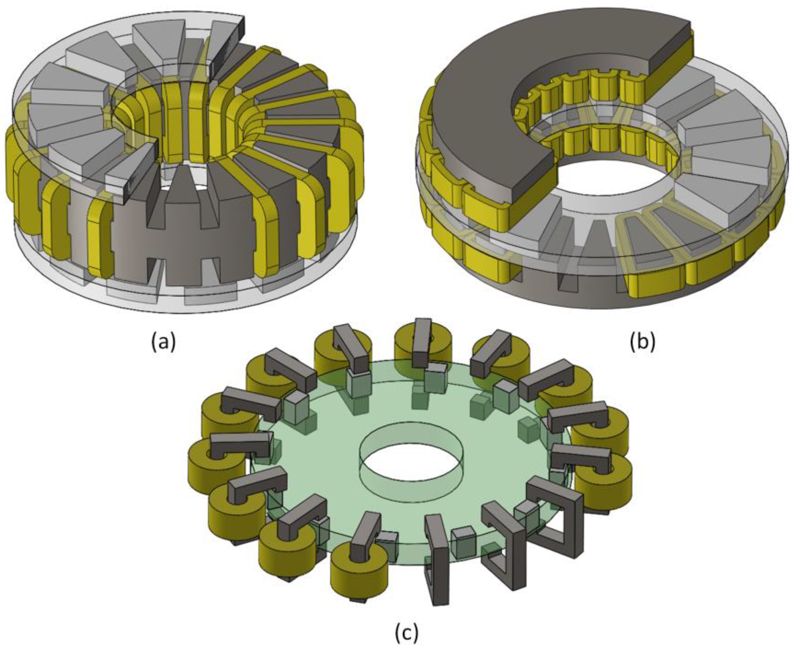
2.1. DSAFSRM’s Design Equations
2.2. Non-Linear MEC
2.2.1. Permeance Network
2.2.2. Air Gap Permeances
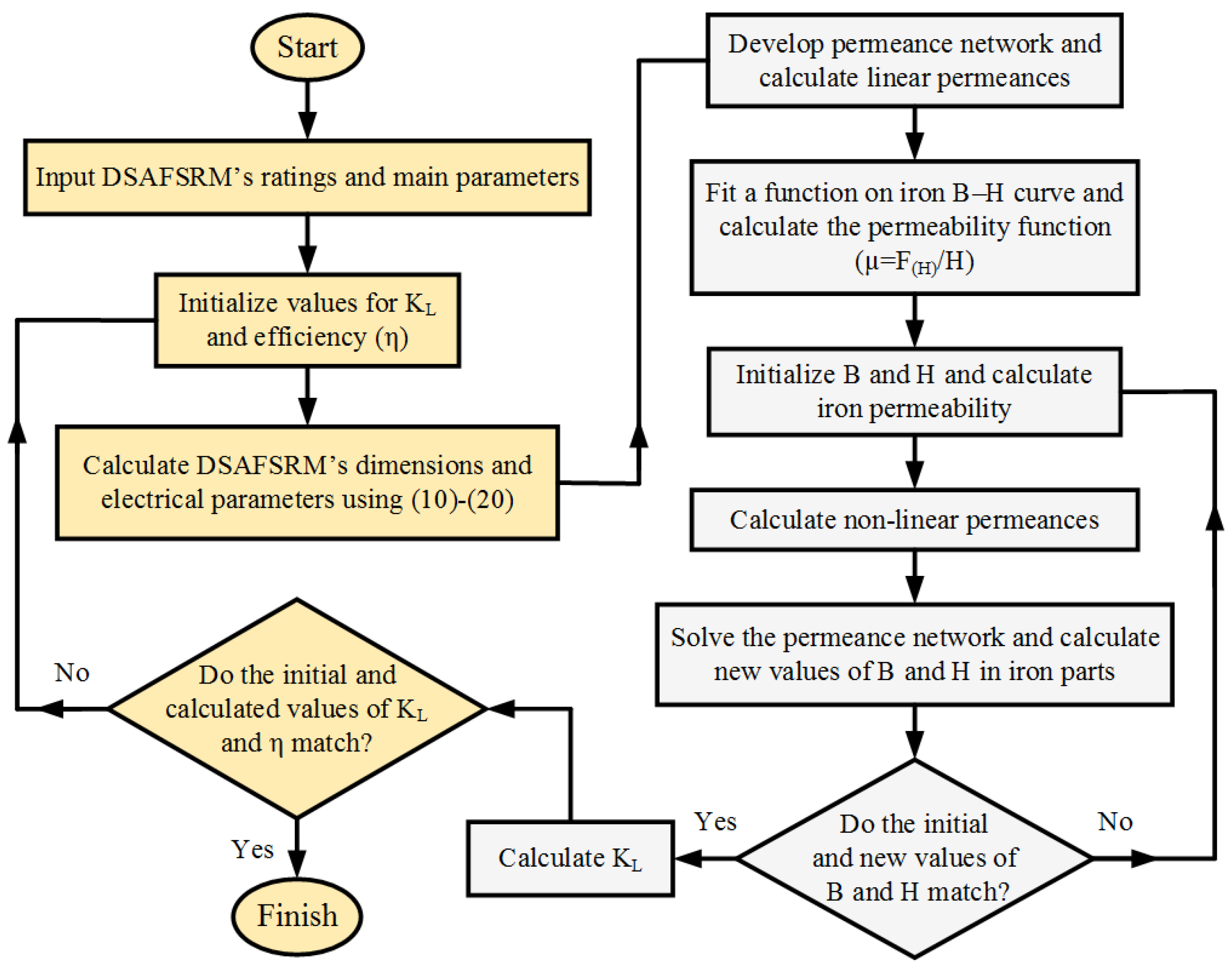
2.2.3. Non-Linear Hybrid Algorithm
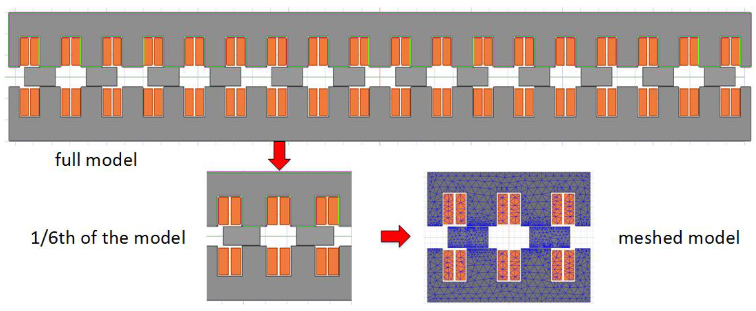
3. Electromagnetic Performance Analysis
4. Torque Ripple Minimization
4.1. Conventional Pole Coverage Optimization
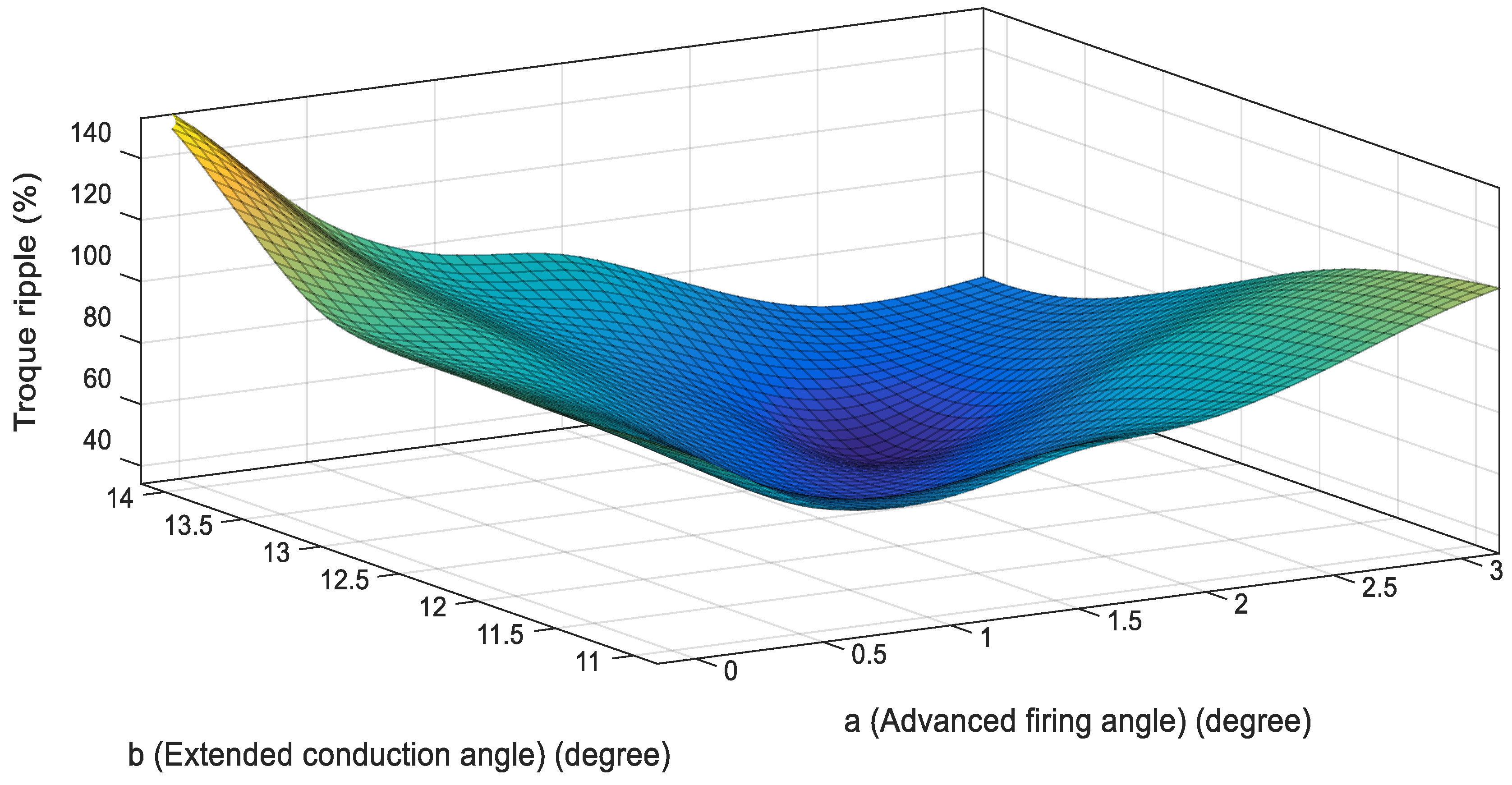
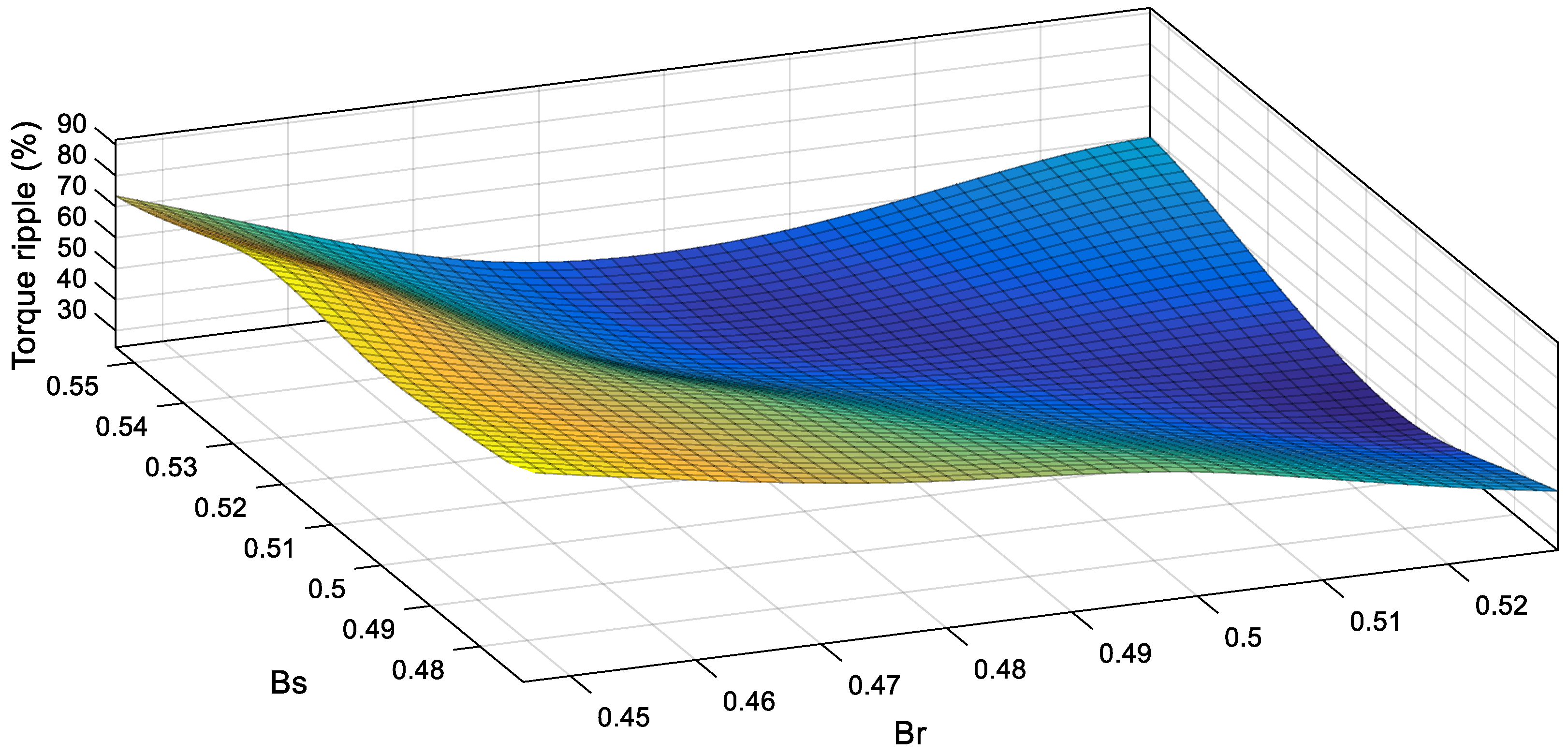
4.2. Proposed Two-Step Optimization
5. Comparative Analysis
6. Conclusions
Author Contributions
Funding
Data Availability Statement
Conflicts of Interest
Appendix A
References
- Xu, Z.; Li, T.; Zhang, F.; Wang, H.; Dee, J.; Ahn, J.-W. Characteristics Evaluation of a Segmental Rotor Type Switched Reluctance Motor with Concentrated Winding for Torque Density and Efficiency Improvement. Energies 2022, 15, 8915. [Google Scholar] [CrossRef]
- Andriushchenko, E.; Kallaste, A.; Mohammadi, M.H.; Lowther, D.A.; Heidari, H. Sensitivity Analysis for Multi-Objective Optimization of Switched Reluctance Motors. Machines 2022, 10, 559. [Google Scholar] [CrossRef]
- Diao, K.; Sun, X.; Lei, G.; Guo, Y.; Zhu, J. Multimode optimization of switched reluctance machines in hybrid electric vehicles. IEEE Trans. Energy Convers. 2020, 36, 2217–2226. [Google Scholar] [CrossRef]
- Terzić, M.V.; Mihić, D.S. Switched Reluctance Motor Design for a Mid-Drive E-Bike Application. Machines 2022, 10, 642. [Google Scholar] [CrossRef]
- Watthewaduge, G.; Bilgin, B. Sizing of the Motor Geometry for an Electric Aircraft Propulsion Switched Reluctance Machine Using a Reluctance Mesh-Based Magnetic Equivalent Circuit. Machines 2023, 11, 59. [Google Scholar] [CrossRef]
- Zine, M.; Chemsa, A.; Labiod, C.; Ikhlef, M.; Srairi, K.; Benbouzid, M. Coupled indirect torque control and maximum power point tracking technique for optimal performance of 12/8 switched reluctance generator-based wind turbines. Machines 2022, 10, 1046. [Google Scholar] [CrossRef]
- Xu, Z.; Li, T.; Zhang, F.; Zhang, Y.; Lee, D.-H.; Ahn, J.-W. A Review on Segmented Switched Reluctance Motors. Energies 2022, 15, 9212. [Google Scholar] [CrossRef]
- Ghaheri, A.; Naghash, R.; Ajamloo, A.M.; Afjei, E. Design Comparison of BLDC and SR Motor Drives for Range Hood Applications. In Proceedings of the 2021 29th Iranian Conference on Electrical Engineering (ICEE), Tehran, Iran, 18–20 May 2021; pp. 220–225. [Google Scholar]
- Nasiri-Zarandi, R.; Ajamloo, A.M. Implementation of PM step skew technique to optimum design of a transverse flux PM generator for small scale wind turbine. In Proceedings of the 2019 IEEE Milan PowerTech, Milan, Italy, 23–27 June 2019; pp. 1–6. [Google Scholar]
- Lukman, G.F.; Nguyen, X.S.; Ahn, J.-W. Design of a low torque ripple three-phase SRM for automotive shift-by-wire actuator. Energies 2020, 13, 2329. [Google Scholar] [CrossRef]
- Lan, Y.; Frikha, M.A.; Croonen, J.; Benômar, Y.; El Baghdadi, M.; Hegazy, O. Design Optimization of a Switched Reluctance Machine with an Improved Segmental Rotor for Electric Vehicle Applications. Energies 2022, 15, 5772. [Google Scholar] [CrossRef]
- Garcia-Amorós, J.; Marín-Genescà, M.; Andrada, P.; Martínez-Piera, E. Two-phase linear hybrid reluctance actuator with low detent force. Energies 2020, 13, 5162. [Google Scholar] [CrossRef]
- Gupta, T.D.; Chaudhary, K.; Elavarasan, R.M.; Saket, R.; Khan, I.; Hossain, E. Design modification in single-tooth winding double-stator switched reluctance motor for torque ripple mitigation. IEEE Access 2021, 9, 19078–19096. [Google Scholar] [CrossRef]
- Zhao, G.; Hua, W.; Qi, J. Comparative study of wound-field flux-switching machines and switched reluctance machines. IEEE Trans. Ind. Appl. 2019, 55, 2581–2591. [Google Scholar] [CrossRef]
- Ajamloo, A.M.; Ghaheri, A.; Nasiri-Zarandi, R. Design and Optimization of a New TFPM Generator with Improved Torque Profile. In Proceedings of the 2019 International Power System Conference (PSC), Tehran, Iran, 9–11 December 2019; pp. 106–112. [Google Scholar]
- Gundogmus, O.; Elamin, M.; Yasa, Y.; Husain, T.; Sozer, Y.; Kutz, J.; Tylenda, J.; Wright, R.L. Acoustic noise mitigation of switched reluctance machines with windows on stator and rotor poles. IEEE Trans. Ind. Appl. 2020, 56, 3719–3730. [Google Scholar] [CrossRef]
- Lukman, G.F.; Ahn, J.-W. Torque ripple reduction of switched reluctance motor with non-uniform air-gap and a rotor hole. Machines 2021, 9, 348. [Google Scholar] [CrossRef]
- Azer, P.; Bilgin, B.; Emadi, A. Comprehensive analysis and optimized control of torque ripple and power factor in a three-phase mutually coupled switched reluctance motor with sinusoidal current excitation. IEEE Trans. Power Electron. 2020, 36, 7150–7164. [Google Scholar] [CrossRef]
- Wang, J.; Jiang, W.; Wang, S.; Lu, J.; Williams, B.W.; Wang, Q. A novel step current excitation control method to reduce the torque ripple of outer-rotor switched reluctance motors. Energies 2022, 15, 2852. [Google Scholar] [CrossRef]
- Li, H.; Bilgin, B.; Emadi, A. An improved torque sharing function for torque ripple reduction in switched reluctance machines. IEEE Trans. Power Electron. 2018, 34, 1635–1644. [Google Scholar] [CrossRef]
- Sun, X.; Wu, J.; Lei, G.; Guo, Y.; Zhu, J. Torque ripple reduction of SRM drive using improved direct torque control with sliding mode controller and observer. IEEE Trans. Ind. Electron. 2020, 68, 9334–9345. [Google Scholar] [CrossRef]
- Kawa, M.; Kiyota, K.; Furqani, J.; Chiba, A. Acoustic noise reduction of a high-efficiency switched reluctance motor for hybrid electric vehicles with novel current waveform. IEEE Trans. Ind. Appl. 2018, 55, 2519–2528. [Google Scholar] [CrossRef]
- Jing, B.; Dang, X.; Liu, Z.; Ji, J. Torque Ripple Suppression of Switched Reluctance Motor with Reference Torque Online Correction. Machines 2023, 11, 179. [Google Scholar] [CrossRef]
- Zhu, J.; Cheng, K.W.E.; Xue, X. Design and analysis of a new enhanced torque hybrid switched reluctance motor. IEEE Trans. Energy Convers. 2018, 33, 1965–1977. [Google Scholar] [CrossRef]
- Kondelaji, M.A.J.; Farahani, E.F.; Mirsalim, M. Performance analysis of a new switched reluctance motor with two sets of embedded permanent magnets. IEEE Trans. Energy Convers. 2020, 35, 818–827. [Google Scholar] [CrossRef]
- Ding, W.; Yang, S.; Hu, Y.; Li, S.; Wang, T.; Yin, Z. Design consideration and evaluation of a 12/8 high-torque modular-stator hybrid excitation switched reluctance machine for EV applications. IEEE Trans. Ind. Electron. 2017, 64, 9221–9232. [Google Scholar] [CrossRef]
- Yan, W.; Chen, H.; Liao, S.; Liu, Y.; Cheng, H. Design of a low-ripple double-modular-stator switched reluctance machine for electric vehicle applications. IEEE Trans. Transp. Electrif. 2021, 7, 1349–1358. [Google Scholar] [CrossRef]
- Cheng, H.; Liao, S.; Yan, W. Development and performance analysis of segmented-double-stator switched reluctance machine. IEEE Trans. Ind. Electron. 2021, 69, 1298–1309. [Google Scholar] [CrossRef]
- Ghaffarpour, A.; Mirsalim, M. Split-tooth double-rotor permanent magnet switched reluctance motor. IEEE Trans. Transp. Electrif. 2022, 8, 2400–2411. [Google Scholar] [CrossRef]
- Torkaman, H.; Ghaheri, A.; Keyhani, A. Axial flux switched reluctance machines: A comprehensive review of design and topologies. IET Electr. Power Appl. 2019, 13, 310–321. [Google Scholar] [CrossRef]
- Madhavan, R.; Fernandes, B. A novel axial flux segmented SRM for electric vehicle application. In Proceedings of the XIX International Conference on Electrical Machines-ICEM 2010, Rome, Italy, 6–8 September 2010; pp. 1–6. [Google Scholar]
- Madhavan, R.; Fernandes, B.G. Axial flux segmented SRM with a higher number of rotor segments for electric vehicles. IEEE Trans. Energy Convers. 2013, 28, 203–213. [Google Scholar] [CrossRef]
- Yu, F.; Chen, H.; Yan, W.; Pires, V.F.; Martins, J.F.; Rafajdus, P.; Musolino, A.; Sani, L.; Aguirre, M.P.; Saqib, M.A. Design and Multiobjective Optimization of A Double-stator Axial Flux SRM with Full-pitch Winding Configuration. IEEE Trans. Transp. Electrif. 2022, 8, 4348–4364. [Google Scholar] [CrossRef]
- Ma, J.; Qu, R.; Li, J. Optimal design of axial flux switched reluctance motor for electric vehicle application. In Proceedings of the 2014 17th International Conference on Electrical Machines and Systems (ICEMS), Hangzhou, China, 22–25 October 2014; pp. 1860–1865. [Google Scholar]
- Labak, A.; Kar, N.C. Designing and prototyping a novel five-phase pancake-shaped axial-flux SRM for electric vehicle application through dynamic FEA incorporating flux-tube modeling. IEEE Trans. Ind. Appl. 2013, 49, 1276–1288. [Google Scholar] [CrossRef]
- Labak, A.; Kar, N.C. A novel five-phase pancake shaped switched reluctance motor for hybrid electric vehicles. In Proceedings of the 2009 IEEE Vehicle Power and Propulsion Conference, Dearborn, MI, USA, 7–11 September 2009; pp. 494–499. [Google Scholar]
- Andrada, P.; Blanqué, B.; Martínez, E.; Perat, J.I.; Sánchez, J.A.; Torrent, M. Design of a novel modular axial-flux double rotor switched reluctance drive. Energies 2020, 13, 1161. [Google Scholar] [CrossRef] [Green Version]
- Teixeira, V.S.D.C.; Barros, T.A.D.S.; Moreira, A.B.; Ruppert Filho, E. Methodology for the electromagnetic design of the axial-flux C-core switched reluctance generator. IEEE Access 2018, 6, 65463–65473. [Google Scholar] [CrossRef]
- Ma, J.; Li, J.; Fang, H.; Li, Z.; Liang, Z.; Fu, Z.; Xiao, L.; Qu, R. Optimal design of an axial-flux switched reluctance motor with grain-oriented electrical steel. IEEE Trans. Ind. Appl. 2017, 53, 5327–5337. [Google Scholar] [CrossRef]
- Sun, W.; Li, Q.; Liu, K.; Li, L. Design and analysis of a novel rotor-segmented axial-field switched reluctance machine. CES Trans. Electr. Mach. Syst. 2017, 1, 238–245. [Google Scholar] [CrossRef]
- Sun, W.; Li, Q.; Sun, L.; Li, L. Development and investigation of novel axial-field dual-rotor segmented switched reluctance machine. IEEE Trans. Transp. Electrif. 2020, 7, 754–765. [Google Scholar] [CrossRef]
- Krishnan, R. Switched Reluctance Motor Drives: Modeling, Simulation, Analysis, Design, and Applications; CRC Press: Boca Raton, FL, USA, 2017. [Google Scholar]
- Gieras, J.F. Permanent Magnet Motor Technology: Design and Applications; CRC Press: Boca Raton, FL, USA, 2009. [Google Scholar]
- Ostovic, V. Dynamics of Saturated Electric Machines; Springer Science & Business Media: Berlin/Heidelberg, Germany, 2012. [Google Scholar]


| Parameter | Symbol | Value |
|---|---|---|
| Output power (kW) | Po | 100 |
| Nominal speed (rpm) | nm | 3000 |
| DC link voltage (V) | Vdc | 440 |
| Outer diameter (mm) | Do | 370 |
| Inner diameter (mm) | Di | 148 |
| Active length (mm) | Lm | 111 |
| Number of stator poles | Ns | 18 |
| Number of rotor poles | Nr | 12 |
| Air gap length per side (mm) | Lg | 0.5 |
| Number of turns per coil | Nc | 5 |
| Stator slot opening (mm) | Wss | 20 |
| Stator slot depth (mm) | Tst | 28 |
| Stator yoke thickness | Tsy | 18 |
| Rotor length | Trt | 18 |
| Slot fill factor | Ff | 50 |
| Parameter | Optimized DSAFSRM | Non-Optimized DSAFSRM | Double-Sided Radial Flux SRM |
|---|---|---|---|
| Rated speed (rpm) | 3000 | ||
| Outer diameter (mm) | 370 | ||
| Active length (mm) | 111 | ||
| Current density (A/mm2) | 8 | ||
| Air gap length (mm) | 0.5 | ||
| Output power (kW) | 100 | 99.7 | 79.5 |
| Copper loss (kW) | 2.4 | 2.3 | 2.1 |
| Core loss (kW) | 1.5 | 1.8 | 1.7 |
| Efficiency (%) | 96.2 | 96 | 95.4 |
| Power density (W/cm3) | 8.38 | 8.35 | 6.66 |
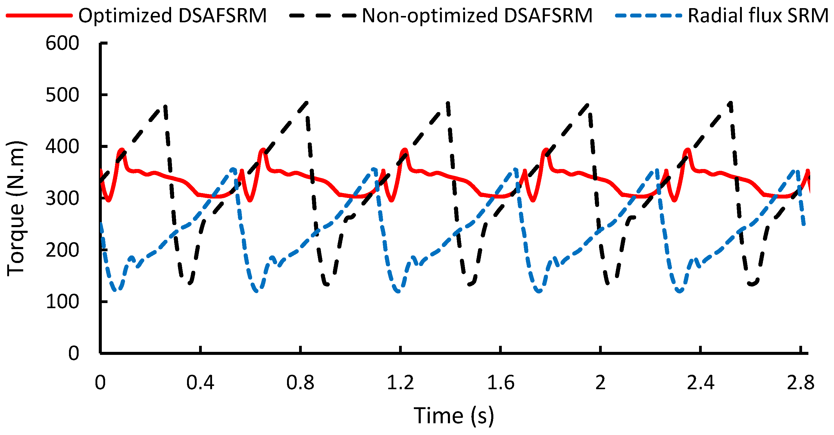
| Torque ripple (%) | 35 | 120 | 92 |
Disclaimer/Publisher’s Note: The statements, opinions and data contained in all publications are solely those of the individual author(s) and contributor(s) and not of MDPI and/or the editor(s). MDPI and/or the editor(s) disclaim responsibility for any injury to people or property resulting from any ideas, methods, instructions or products referred to in the content. |
© 2023 by the authors. Licensee MDPI, Basel, Switzerland. This article is an open access article distributed under the terms and conditions of the Creative Commons Attribution (CC BY) license (https://creativecommons.org/licenses/by/4.0/).
Share and Cite
Ajamloo, A.M.; Ibrahim, M.N.; Sergeant, P. Design, Modelling and Optimization of a High Power Density Axial Flux SRM with Reduced Torque Ripple for Electric Vehicles. Machines 2023, 11, 759. https://doi.org/10.3390/machines11070759
Ajamloo AM, Ibrahim MN, Sergeant P. Design, Modelling and Optimization of a High Power Density Axial Flux SRM with Reduced Torque Ripple for Electric Vehicles. Machines. 2023; 11(7):759. https://doi.org/10.3390/machines11070759
Chicago/Turabian StyleAjamloo, Akbar Mohammadi, Mohamed N. Ibrahim, and Peter Sergeant. 2023. "Design, Modelling and Optimization of a High Power Density Axial Flux SRM with Reduced Torque Ripple for Electric Vehicles" Machines 11, no. 7: 759. https://doi.org/10.3390/machines11070759