Article

Phasor-Like Interpretation of the Angular Velocity of the Wheels of Omnidirectional Mobile Robots

Robotics Laboratory, Universitat de Lleida, Jaume II, 69, 25001 Lleida, Spain
*
Author to whom correspondence should be addressed.
Machines 2023, 11(7), 698; https://doi.org/10.3390/machines11070698
Submission received: 16 May 2023 / Revised: 20 June 2023 / Accepted: 28 June 2023 / Published: 1 July 2023
(This article belongs to the Special Issue Mobile Robotics: Mathematics, Models and Methods)

Abstract

:
Omnidirectionality is a feature that allows motion in any direction without orientation maneuvers. Omnidirectional mobile robots are usually based on omni or mecanum wheels. The motion of an omnidirectional mobile robot is defined by a target motion command M = v , α , ω , where v is the module of the translational velocity; α is the angular orientation of the translational velocity, and ω is the angular velocity of the mobile robot. The motion is achieved by converting the target motion command into the target angular velocities that must be applied to the active wheels of the robot. This work proposes a simplified phasor-like interpretation of the relationship between the parameters of a specific motion command and the angular velocities of the wheels. The concept of phasor-like notation is validated from the analysis of the kinematics of omnidirectional mobile robots using omni wheels and mecanum wheels. This simplified phasor-like notation fosters unconstrained conceptual design of single-type and hybrid multi-wheeled omnidirectional mobile robots without the distribution or type of wheels being a design constraint.

1. Introduction

Omnidirectional transportation vehicles are being used in various heavy-duty industrial applications [1,2] such as logistics [3] and intelligent manufacturing [4] due to their capabilities of navigating in narrow spaces [5,6]. Omnidirectional mobile robots are holonomic platforms that are able to move in any direction while rotating because their translational and rotational motions can be controlled independently [7,8,9]. Omnidirectional motion systems allow minimizing the total path required to navigate between two points while simultaneously moving sideways, which is not possible in the case of two-wheeled mobile robots [9,10]. The combination of an omnidirectional motion system with an optimized tracking system allows an omnidirectional mobile robot to follow any trajectory [11,12,13,14]. A detailed overview of omnidirectional locomotion strategies used in wheeled mobile robots can be found in Tagliavini et al. [15].
Figure 1 shows three omnidirectional wheels commonly used in mobile robots: (a) omni wheel, (b) optimal omni wheel, and (c) mecanum. The common characteristic of omnidirectional wheels is the use of free rollers placed on the external wheel perimeter. Rollers can rotate freely around their axis while the wheel turns around its axis, providing the wheel with two degrees of freedom; the first is the rotation around the wheel axis, and the second is the motion perpendicular to the roller axis. The omni wheel (Figure 1a) was invented in 1919 by Grabowiecki [16] and improved by Blumrich in 1972 [17]. Its free rollers are arranged with a characteristic 0° angular orientation of the free rolling direction relative to the wheel rotation axis. Figure 1b shows the optimal implementation of an omni wheel that combines rollers of different sizes in order to minimize the inner gap between rollers and minimize the generation of vibrations [18]. The mecanum wheel (Figure 1c), also known as the Swedish wheel [19], was invented in 1973 by Ilon [20]. Its free rollers are arranged with a characteristic 45° angular orientation of the free rolling direction relative to the wheel rotation axis [21].
The main difference between omni wheels (Figure 1a,b) and mecanum wheels (Figure 1c) is the angular orientation of the free rollers. This different orientation generates two different patterns in the point of contact of the wheel with the ground; the omni wheel generates a straight contact line, while the mecanum wheel generates a zigzagged contact line. This different contact profile means that the mecanum wheel has to slide when the omnidirectional platform has to rotate.
The rotation of the wheel and its rollers always produces a combination of both forward displacement (or reverse, in the wheel rotation direction) and inward displacement (or outward, in the free rolling direction) depending on the angle of the rollers and the rotation direction of the wheels [22]. The combination of several wheels defines an omnidirectional platform that has three degrees of freedom, allowing translation along the X-axis and Y-axis directions, and rotation around the central Z-axis of the mobile system. As a consequence, an omnidirectional platform is able to implement any motion command M = v , α , ω [23], where v is the module of the translational velocity of the motion, α is the angular orientation of the translational velocity, and ω is the angular velocity of the platform while performing the translation. Figure 2a represents a motion command in an omnidirectional mobile robot with three optimal omni wheels, and Figure 2b represents that in a case with four mecanum wheels. The free rollers are depicted with lines representing their rotation axis. The rollers in contact with the floor are represented with wider lines.
In the scientific literature, there are proposals of omnidirectional mobile robots using diverse wheels and chassis configurations [3,23,24]. The most frequent ones are based on symmetric designs [23,25] using three omni wheels [26,27] or using four mecanum wheels [24,28,29]. Alternative proposals include asymmetric wheel distributions [23,30] and platforms with six [31,32,33] or eight wheels [34]. There are also other promising omnidirectional motion systems such as that used to create a statically stable ball robot in which the robot structure is built and balanced on the top of a ball [35], and spherical robots, which are mainly composed of a ball-shaped shell with the internal robot structure based on a pendulum [36,37].
The use of omni wheels and mecanum wheels has the disadvantage that they only transmit part of the motor torque in the motion direction as a result of the free sliding of the rollers. This effect reduces motion efficiency in the omnidirectional mobility provided by these types of wheels. In this direction, Zhang et al. [38] and Hou et al. [39] analyzed the power consumption of two omnidirectional platforms using three omni wheels and four mecanum wheels. Galati et al. [6] summarized that a platform using four mecanum wheels allows the effective use of 50% of the motors’ power when translating along the axis of a wheel, and 71% when translating at 45° relative to an axis of a wheel; a platform using three omni wheels allows the effective use of 47% of the motors’ power when translating along the axis of a wheel, and up to 68% when translating at 30° relative to the axis of a wheel.
Despite this known power efficiency disadvantage, the exceptional possibilities offered by omnidirectional mobility have fostered the development of a substantial number of mobile robot applications; some of them are listed hereafter. Samani et al. [40] proposed an omnidirectional soccer player robot based on omni wheels. In this case, the omnidirectional motion system, the mechanical structure, the control system, the odometry system, the vision sensors for self-localization, and the software required to perform as soccer player robot were integrated to achieve a mobile robot with no head direction. This approach was able to respond quickly to the game while being capable to implement sophisticated behaviors such as ball passing or goalkeeping. Gao et al. [22] presented a floor-cleaning robot with a motion system using four mecanum wheels specially designed for crowded public applications. Tian et al. [34] introduced a method for motion compensation in order to improve the motion accuracy of an omnidirectional mobile robot using eight mecanum wheels. This approach was proposed in order to develop a big transportation platform with a larger wheel surface area in contact with the ground. Peng et al. [41] developed an omnidirectional platform for automatic material conveying in a production line using four mecanum wheels. The platform included a damping suspension mechanism in order to avoid the noise and vibrations caused by the gap and discontinuities of the small solid rollers in contact with the ground [42]. Yang et al. [43] implemented an omnidirectional palletizing robot using four mecanum wheels. The robot was aimed at transporting, stacking, and unstacking large quantities of workpieces or packages in an industrial production process. Wang et al. [44] proposed the OuijaBot mobile robot using four mecanum wheels and a distributed force and torque controller to manage a group of robots that collectively transport objects with both translation and rotation control. In this case, no explicit communication among robots was required to collectively transport the objects. The OuijaBot concept was experimentally tested with a square platform using four mobile robots and a total of 16 mecanum wheels [45]. In a similar direction, Li et al. [46] presented a velocity compensation method to provide an accurate motion control in combinations of multiple mecanum mobile robots created to transport large-scale objects. Galati et al. [5] designed and tested a four-wheeled mecanum robot for industrial applications. Galati et al. [5] highlighted that the variability in the effective point of contact of the mecanum wheel with the floor generates slippages and vibrations that affect the accuracy of the pose estimated with the odometry. These undesired effects were minimized using an adaptive estimation framework that considers the properties of the surface traversed to adjust the control of the mobile robot. Lastly, Eirale et al. [47] presented an autonomous omnidirectional robot designed to assist elderly and reduced-mobility people in domestic environments. The robot is based on four mecanum wheels and a modular layer-based architecture including perception and vocal control. The main service functions of the robot include monitoring of elderly, telepresence, and night assistance. Eirale et al. [47] qualitatively tested the platform in a domestic-like environment to evaluate deep learning solutions for visual perception and vocal commands, running on the embedded hardware of the robot.
The target angular velocities that must be applied to the different wheels of an omnidirectional mobile robot depend on the number, type, radius, and alignment of the wheels used. Omni wheels and mecanum wheels performing the same motion require different angular velocities; in both cases, the angular velocity of each wheel is defined by the inverse kinematics of the omnidirectional platform.
In the scientific literature, there are several proposals providing a general kinematic formulation to model mobile robots using omni wheels and mecanum wheels. Siradjuddin et al. [48] developed a general inverse kinematic model for the design of omnidirectional mobile robots. The formulation presented was simulated and discussed in the case of mobile robots using three omni wheels, four mecanum wheels, and six omni wheels. Li et al. [23] theoretically analyzed platforms with mecanum wheels arranged in different configurations. The general objective was the creation of suitable multiple-mecanum-wheeled configurations for omnidirectional platforms. Their proposal could be applied for single and multiple mobile robot configurations such as end-to-end, side-by-side, symmetrical rectangular, and distributed combinations. Almasri et al. [25] presented a compact mathematical model optimized for the design of omnidirectional platforms using symmetrical distributions of N omni wheels in order to optimize the trajectory of the motion. The common objective of all these cited models is to simplify the implementation of omnidirectional platforms that must meet some design specifications.

New Contribution

The new contribution of this work is the proposal of a phasor-like interpretation of the angular velocity of the wheels of an omnidirectional mobile robot. This new proposal is based on the observation of the sinusoidal relationship between the angular velocity of the wheels ω 1 , , ω N and the parameters of a specific motion command M = v , α , ω applied to the robot. The interpretation of this relationship was found to be similar to the phasor notation proposed by Steinmetz et al. [49,50] to simplify the analysis of electrical circuits. The concept of phasor-like notation has been validated from the analysis of the kinematics of omnidirectional mobile robots using omni wheels and mecanum wheels.
Relative to the related scientific literature [23,25,48], this proposal has the advantage of providing a direct and simplified estimation of the angular velocity of the wheels of an omnidirectional platform without requiring the computation of its inverse kinematic matrix. Additionally, the phasor-like notation is not limited to one single type of wheel [23,48] and does not have symmetry limitations [25]. The combination of all these factors simplifies the conceptual design of single-type and hybrid multi-wheeled omnidirectional platforms according to basic design specifications.
The paper is structured as follows. Section 2 describes the materials and methods used in this work (an omnidirectional mobile robot using three omni wheels, an omnidirectional mobile robot using four mecanum wheels, and the inverse kinematics of both robots); Section 3 and Section 4 represent the evolution of the angular velocities of the wheels of both robots relative to the motion command; Section 5 and Section 6 propose the phasor-like interpretation of the angular velocities of their wheels; Section 7 presents a wider application of the phasor-like notation in the simplified conceptual design of omnidirectional mobile robots using three asymmetric omni wheels of different radii, four symmetric omni wheels, four asymmetric mecanum wheels of two different radii, eight mecanum wheels, and a hybrid combination of four mecanum and two omni wheels; final remarks are given in Section 8.

2. Materials and Methods

The materials used in this work were an omnidirectional mobile robot with three optimal omni wheels and an omnidirectional mobile robot with four mecanum wheels, because these are the most simple and common configurations providing omnidirectional motion [23,51]. The methods used in this work were the inverse kinematic expressions of the mobile robots, which allowed the computation of the angular velocities of the N wheels of the robot ω 1 , , ω N required to implement a specific target motion command M = v , α , ω b defined in the mobile robot frame b (see Figure 2).

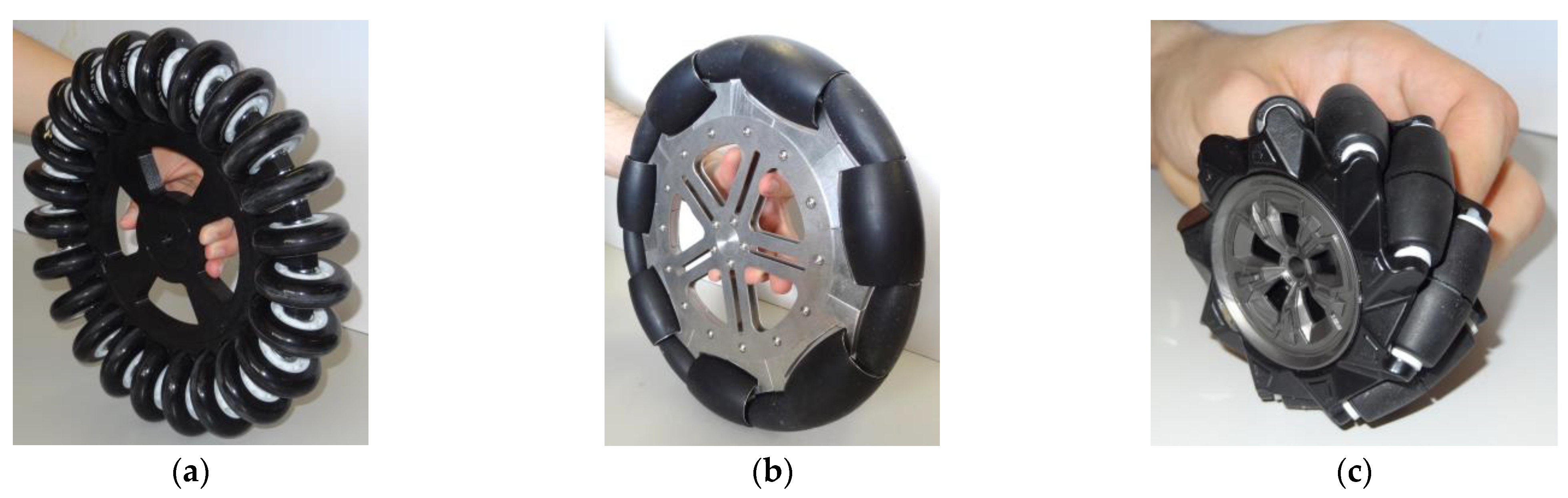
2.1. Three-Wheeled Omni Mobile Robot (3WOMR)

The reference omnidirectional mobile robot using three omnidirectional wheels was the APR-02 prototype [27]. Figure 3a shows the mobile robot, and Figure 3b details its omnidirectional motion system, which is based on the use of three optimal omni wheels with the rolling direction of the passive rollers oriented at 0° relative to the wheel axis. Optimal omni wheels have the advantage of reducing the gap between free rollers and the vibrations transferred to the mobile robot structure. Henceforward, optimal omni wheels are referred as omni wheels or omni, for short. This notation emphasizes differentiation between the two types of wheels: omni and mecanum. The APR-02 mobile robot has been applied as a walk-helper assistant [52], and as a tool to evaluate the control of the wheels [53] and the odometry error of a three-wheeled omnidirectional motion system [54].
Figure 4a shows the system frames and motion parameters of a three-wheeled omnidirectional mobile robot, where b represents the mobile robot frame, w i represents the frames of the three wheels, v , α , ω represents the motion command M , ω i is the positive direction of the angular velocities of the wheels, and the black arrow indicates the forward direction of motion. Additionally, Figure 4b represents the main dimensional parameters of the wheels, where d i is the distance between the centroids of the robot and wheel i , δ i is the angle between the x b axis of the mobile robot frame b and the line joining the centroids of the robot and the wheels, and r w i is the radius of the three wheels. Table 1 shows the values of the main dimensional parameters of the APR-02 mobile robot.

2.2. Four-Wheeled Mecanum Mobile Robot (4WMMR)

The reference omnidirectional mobile robot using four mecanum omnidirectional wheels was the OSOYOO ZZ012318MC kit for Arduino Mega [55]. Figure 5a shows the mobile robot, and Figure 5b details its omnidirectional motion system using four mecanum wheels that include passive rollers with a rolling direction oriented at ±45° relative to the wheel axis. This do-it-yourself (DIY) mobile robot is used as a rapid test tool of motion algorithms. Dhanasekar et al. [56] used this tool to evaluate the efficacy of a software-based monitoring solution proposed to reduce accidents in roadway settings where human-driven and autonomous cars are integrated. Bajracharya et al. [57] analyzed the use of different learning kits in education. Almassri et al. [58] developed an artificial neural network (ANN) to combine measurements from inertial measurement units (IMUs) and time-of-flight (TOF) measurements from an ultra-wideband (UWB) system with OptiTrack Motion Capture System (OptiT-MCS) data to guarantee the positioning accuracy of the mobile robot in indoor environments. Georgeon et al. [59] analyzed the self-localization problem and the active inference of obstacle properties using coarse sensors.
Figure 6a shows the system frames and motion parameters of a four-wheeled mecanum omnidirectional mobile robot, where b represents the mobile robot frame, w i represents the frames of the four wheels, v , α , ω represents the motion command M , ω i is the positive direction of the angular velocities of the wheels, and the black arrow indicates the forward direction of the motion. Additionally, Figure 6b represents the main dimensional parameters of the wheels, where d i is the radial distance between the centroids of the robot and wheel i , δ i is the angle between the x b axis of the mobile robot frame b and the line joining the centroids of the robot and the wheels, and r w i is the radius of the four wheels. In the context of mecanum mobile robots, the coordinates of the wheels relative to the mobile robot frame x i , y i and the absolute value of these coordinates l x , l y are more frequently used than the radial distance of the wheels d i . Table 2 shows the values of the dimensional parameters of the OSOYOO mobile robot.

2.3. Inverse Kinematics of a Three-Wheeled Omni Mobile Robot (3WOMR)

The inverse kinematics of a mobile robot defines the mathematical expressions required to compute the angular velocities of the wheels according to a specific motion command. The inverse kinematic model of the omnidirectional mobile robot APR-02 was discussed in Palacín et al. [14]:
ω 1 ω 2 ω 3 = 1 r w 1 0 0 0 1 r w 2 0 0 0 1 r w 3 · sin δ 1 cos   δ 1 d 1 sin δ 2 cos   δ 2 d 2 sin δ 3 cos   δ 3 d 3 · v cos α v sin α ω b ,
where the angular orientation of the free rollers (0°) placed on the perimeter of the omni wheels is implicitly included.

2.4. Inverse Kinematics of a Four-Wheeled Mecanum Mobile Robot (4WMMR)

The inverse kinematic model of the omnidirectional mobile robot OSOYOO using four mecanum wheels is based on the proposal of Popovici et al. [60,61], which can be expressed in a compact matrix form using
ω 1 ω 2 ω 3 ω 4 = 1 r w 1 0 0 0 0 1 r w 2 0 0 0 0 1 r w 3 0 0 0 0 1 r w 4 · 1 1 l x + l y 1       1 l x + l y 1 1 l x + l y 1       1 l x + l y · v cos α v sin α ω b ,
where the angular orientation of the free rollers (±45°) placed on the perimeter of the mecanum wheels is implicitly included. This simplified expression is only valid when the main plane of the wheel is oriented parallel to the x b axis of the robot.
In Equation (2), l x and l y are the same for all the wheels and always positive. Alternatively, the coordinates x i , y i of the center of each wheel can be expressed using d i and δ i as follows:
x i = d i cos δ i , y i = d i sin δ i .
Then, Equation (2) becomes
ω 1 ω 2 ω 3 ω 4 = 1 r w 1 0 0 0 0 1 r w 2 0 0 0 0 1 r w 3 0 0 0 0 1 r w 4 · 1 1 d 1 cos δ 1 sin δ 1 1       1 d 2 + cos δ 2 sin δ 2 1 1 d 3 cos δ 3 sin δ 3 1       1 d 4 + cos δ 4 sin δ 4 · v cos α v sin α ω b ,

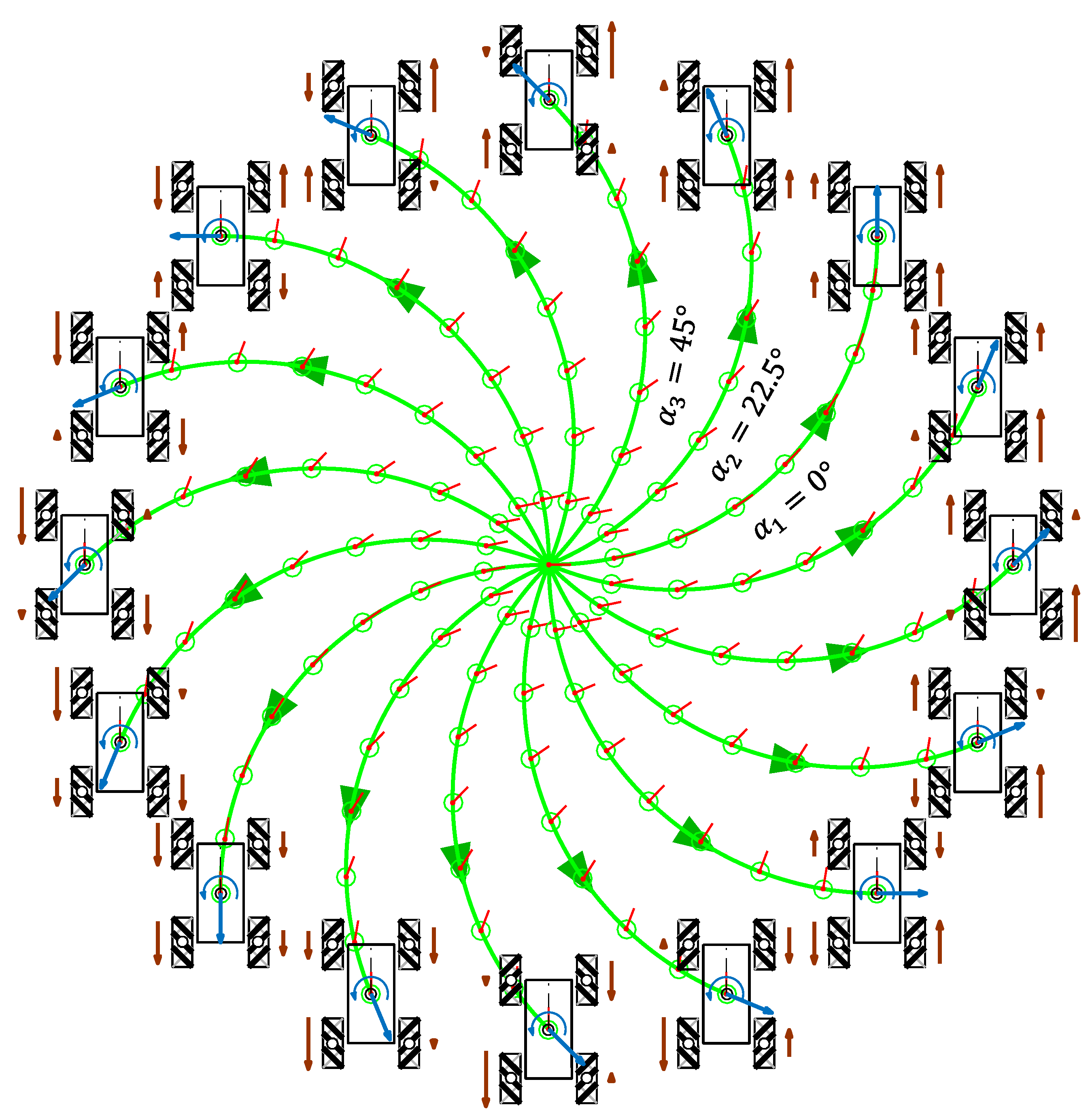
3. Representation of the Angular Velocity of the Wheels of a 3WOMR

The aim of this section is to represent the evolution of the angular velocities of the wheels of a three-wheeled omni mobile robot (3WOMR) as a function of the angular orientation α of the motion. The angular velocities of the wheels were obtained by simulating the execution of the set of trajectory motion commands M = v , α i , ω by the mobile robot, where v is the common translational velocity, ω is the common constant angular velocity, and α i is the specific angular orientation defined in each experiment. The motion command M = v , α i , ω was constant in each of the trajectories simulated; thus, the angular velocities of the wheels ω 1 , ω 2 , ω 3 required to implement the motion were also constant.
Two groups of trajectories are presented, one without angular velocity ( ω = 0 rad/s) and one with angular velocity ( ω = 0.1 rad/s). In each trajectory, the initial position of the mobile robot relative to the world frame was x 0 , y 0 , θ 0 = 0 , 0 , 0 ° . The angular velocities of the APR-02 mobile robot were computed with the inverse kinematic model in Equation (1), and the parameters of the mobile robot used were based on the APR-02 mobile robot [27] (see Table 1).

3.1. Example Trajectories for M = v = 0.3   m / s , α i = 1 116 = 22.5 ° · i 1 , ω = 0   r a d / s

Figure 7 shows the representation of the trajectories of the three-wheeled APR-02 omni mobile robot and a qualitative relative scale representation of the angular velocity of the wheels required to perform each trajectory when ω = 0 rad/s.
In each trajectory, the intermediate mobile robot positions and orientations are represented with a green circle and a short red line. The translational velocity used in the trajectories was v = 0.3 m/s, which is the nominal speed of the APR-02 mobile robot. This simulation was defined in α i steps of 22.5 ° , but only the angular orientations corresponding to α 1 = 0°, α 2 = 22.5°, and α 3 = 45° are labeled in Figure 7 in order to reduce the visual information displayed. Similarly, the simulation time and the length of the trajectories were limited to 16.0 s and 4.80 m for improved visual interpretation of the results. The angular velocity defined in the motion commands was ω = 0 rad/s; thus, the orientation of the mobile robot θ did not change during the displacements. The final position of the robot in each trajectory had different coordinates and the same orientation as in the beginning of the motion x f , y f , 0 ° .
Figure 8 shows the relationship between the angular velocities of the wheels of the robot ω 1 , ω 2 , ω 3 and the angular orientation α of the motion of the mobile robot. This simulation was defined in α i steps of 1 ° . The evolution has a characteristic sinusoidal profile and a phase difference between signals of 120°, which is also characteristic of a three-phase electrical circuit. This similitude inspired the representation of the angular velocities of the wheels using a phasor-like notation.

3.2. Example Trajectories for M = v = 0.3   m / s , α i = 1 16 = 22.5 ° · i 1 , ω = 0.1   r a d / s

Complementarily, Figure 9 shows the representation of the trajectories of a three-wheeled omni mobile robot and a qualitative relative scale representation of the angular velocity of the wheels when ω = 0.1 rad/s.
In each trajectory, the translational velocity was v = 0.3 m/s, and the angular velocity of the mobile robot was ω = 0.1 rad/s; thus, the mobile robot rotated during this motion (and performed circular trajectories [14]). This simulation was also defined in α i steps of 22.5 ° , and only the angular orientations corresponding to α 1 = 0°, α 2 = 22.5°, and α 3 = 45° are labeled in Figure 9 to reduce the visual information displayed. In this case, the duration of the trajectories was adjusted in order to get a final orientation of the mobile robot θ = 90° ( π /2 rad) for improved visual interpretation of the results. The final position of the robot in each trajectory had different coordinates but the same orientation x f , y f , 90 ° . Therefore, the duration of the trajectories was limited to ( θ = ω · t ):
t = θ ω = π 2 rad 0.1   rad / s = 15.7   s ,
and all displacements covered 4.71 m.
Figure 10 shows the relationship between the angular velocities of the wheels ω 1 , ω 2 , ω 3 and the angular orientation α of the motion of the mobile robot. This simulation was defined in α i steps of 1 ° . In the representation of Figure 10, the angular velocity of the wheels was increased to ω = 0.5 rad/s in order to evince the differences from the previous results shown in Figure 8 with ω = 0 rad/s.
The evolution of the angular velocity of the wheels displayed in Figure 10 maintains the characteristic 120° phase difference between signals previously observed in Figure 8, which is characteristic of a three-phase electrical circuit. A detailed comparison of the results from Figure 8 and Figure 10 reveals that the signals maintain the same phase difference between them and the same sinusoidal amplitude. The results also show that there is a shift in the mean value of the angular velocities represented, which was 0 in the previous case with ω = 0 rad/s (Figure 8) but has a nonzero value in the current case with ω = 0.5 rad/s (Figure 10).

4. Representation of the Angular Velocity of the Wheels of a 4WMMR

The aim of this section is to repeat the trajectory experiments presented in the previous section in order to obtain the evolution of the angular velocities of the wheels of a four-wheeled mecanum omnidirectional mobile robot (4WMMR) as a function of the angular orientation α of the motion. The angular velocities represented resulted from the same set of motion commands M = v , α i , ω as before, with constant translational velocity v , constant angular velocity ω , and variable angular orientation α i . The initial position of all the trajectories defined by the set of motion commands was x 0 , y 0 , θ 0 = 0 , 0 , 0 ° relative to the world frame. Again, two groups of trajectories are presented, one without angular velocity ( ω = 0 rad/s) and one with angular velocity ( ω = 0.1 rad/s). The motion command M = v , α i , ω was also constant in each of the trajectories; thus, the angular velocities of the wheels ω 1 , ω 2 , ω 3 ,   ω 4 required to implement the motion were constant. The angular velocities of the OSOYOO mobile robot were computed with the inverse kinematic model in Equation (4), and the parameters of the mobile robot used were based on the OSOYOO mobile robot [55] (see Table 2).

4.1. Example Trajectories for M = v = 0.3   m / s , α i = 1 16 = 22.5 ° · i 1 , ω = 0   r a d / s

As in the omni wheel example, Figure 11 shows the representation of the trajectories of the four-wheeled mecanum OSOYOO mobile robot and a qualitative relative scale representation of the angular velocity of the wheels required to perform each trajectory when ω = 0 rad/s.
As before, the translational velocity along the trajectories was v = 0.3 m/s, the duration was 16.0 s, the trajectory covered 4.8 m, and the angular velocity was ω = 0 rad/s; hence, the orientation of the mobile robot θ did not change during the displacement, and the final position was x f , y f , 0 ° . This simulation was defined in α i steps of 22.5 ° , but only the angular orientations corresponding to α 1 = 0°, α 2 = 22.5°, and α 3 = 45° are labeled in Figure 11 in order to reduce the visual information displayed. Similarly, the simulation time and the length of the trajectories were limited for improved visual interpretation of the results.
Figure 12 shows the relationship between the angular velocities of the wheels of the robot ω 1 , ω 2 , ω 3 , ω 4 and the angular orientation α of the motion of the mobile robot. Again, this simulation was defined in α i steps of 1 ° , and the evolution has a characteristic sinusoidal profile, but the phase difference between signals is 270°. Results show that, when the wheel radii are identical and ω = 0 rad/s, there are only two angular velocity profiles for the four wheels; wheels 1 and 3 have the same velocity while wheels 2 and 4 have the same velocity because of the robot’s symmetry. Hence, this sinusoidal evolution can also be expressed using a phasor-like notation.

4.2. Example Trajectories for M = v = 0.3   m / s , α i = 1 16 = 22.5 ° · i 1 , ω = 0.1   r a d / s

Complementarily, Figure 13 shows the representation of the trajectories of a four-wheeled mecanum mobile robot and a qualitative relative scaled representation of the angular velocity of the wheels when ω = 0.1 rad/s.
Once more, the translational velocity was v = 0.3 m/s, the duration of the motion was 15.7 s, the displacement covered 4.71 m, and the angular velocity of the robot was ω = 0.1 rad/s. Consequently, the mobile robot rotated during this motion [14], and its final orientation was 90 ° ( π /2 rad). This simulation was also defined in α i steps of 22.5 ° , and only the angular orientations corresponding to α 1 = 0°, α 2 = 22.5°, and α 3 = 45° are labeled in Figure 13 to reduce the information displayed. Similarly, the simulation time and the length of the trajectories were limited for improved visual interpretation of the results.
Figure 14 shows the continuous relationship between the angular velocities of the wheels ω 1 , ω 2 , ω 3 , ω 4 and the angular orientation α of the motion of the mobile robot. Again, this simulation was defined in α i steps of 1 ° , and the angular velocity of the wheels of the robot was increased to ω = 0.5 rad/s relative to the representation of Figure 13 in order to evince the differences from the previous results shown in Figure 12 with ω = 0 rad/s.
The evolution of the angular velocity of the wheels displayed in Figure 14 maintains the phase difference between signals of 270° previously observed in Figure 12. Apparently, this phase difference is characteristic of a four-wheeled mecanum omnidirectional mobile robot. Similarly to the three-wheeled case, the comparison of the results from Figure 12 and Figure 14 reveals that the signals maintain the same phase difference between them and the same sinusoidal amplitude. As in the three-wheeled omni robot, there is a shift in the mean value of the angular velocities represented, which was 0 in the previous case with ω = 0 rad/s (Figure 12) but has a nonzero value with ω = 0.5 rad/s in this case (Figure 14).

5. Phasor-Like Interpretation of the Angular Velocity of the Wheels of a 3WOMR

This section presents the new contribution of this work, which is the phasor-like interpretation of the angular velocity of a three-wheeled omni mobile robot (3WOMR) (Figure 8 and Figure 10). In a 3WOMR, the omni wheels have passive rollers in their perimeter with the free rolling direction oriented at 0° relative to the wheel rotation axis. From Equation (1), the angular velocity of a 3WOMR can be generally expressed as
ω i = v 1 r w i cos α sin δ i + sin α cos δ i + ω d i r w i .
The term containing the trigonometric functions can be reformulated using the Fourier [62,63,64] expression:
a cos α + b sin α = a 2 + b 2 sin α + arctan a b .
Then,
ω i = v 1 r w i ( sin δ i ) 2 + cos   δ i 2 sin α + arctan sin δ i cos   δ i + ω d i r w i ,
which results in
ω i = v 1 r w i sin α δ i + ω d i r w i .
In the case of the APR-02 mobile robot (Table 1), with r w i = 0.1480 m, d i = 0.195 m, and δ 1 = 60 ° , δ 2 = 180 ° , δ 3 = 300 ° , Equation (9) can be rewritten, for each wheel, as
ω 1 = v · 6.7568 · sin α 60 ° + ω · 1.3176 , ω 2 = v · 6.7568 · sin α 180 ° + ω · 1.3176 , ω 3 = v · 6.7568 · sin α 300 ° + ω · 1.3176 .
Equations (9) and (10) allow a phasor-like interpretation of the angular velocity of the wheels, ω i , of a three-wheeled omni mobile robot. The proposal of phasor-like notation refers to the use of the angle of the wheels δ i to express the phase of the angular velocity of the wheels ω i . In case of the APR-02 mobile robot, the angular velocities have the same sinusoidal amplitude ( v · 6.7568 ) and the same average shift ( ω · 1.3176 ) relative to the motion command applied to the mobile robot, M = v , α , ω , and to the dimensional parameters r w i and d i . This phasor notation is similar to the mathematical notation used in electrical engineering, A φ + B . In this case, the phasor-like interpretation is based on a sine representation:
A φ + B = A · sin α + φ + B ,
where A identifies the amplitude of the sinusoidal signal, φ is the phase of the sinusoidal signal, and B is the average or DC amplitude superposed to the sinusoidal signal.
Using the phasor-like notation, the expression describing the angular velocity of the wheels can be generally expressed as
ω i = 1 N = v · 1 r w i   δ i + ω · d i r w i .
This phasor-like notation is a compact expression that is mathematically equivalent to the matrix notation used in Equation (1) and the simplified Equation (9). The phasor-like notation describing the angular velocity of the three wheels of the of the APR-02 mobile robot is as follows:
ω 1 = v · 6.7568   60 ° + ω · 1.3176 , ω 2 = v · 6.7568   180 ° + ω · 1.3176 , ω 3 = v · 6.7568   300 ° + ω · 1.3176 .
This expression describes the relationship between the angular velocities of the wheels ω i and the motion command M (displayed in Figure 8 and Figure 10). The phase of the sinusoidal representation of the angular velocities only depends on the angular distribution of the wheels and does not depend on ω , which only generates a shift in the mean value of the angular velocities. This implementation requires a minimum of three omni wheels to guarantee the omnidirectional motion of the robot [23]. The advantage of the phasor-like notation is that it may enable the quick design of omnidirectional mobile robots using N omni wheels, because this notation is focused on the definition of the angular velocity of the wheels.

6. Phasor-Like Interpretation of the Angular Velocity of the Wheels of a 4WMMR

This section completes the new contribution of this work by extending the phasor-like interpretation of the velocity of the wheels of a four-wheeled mecanum mobile robot (4WMMR) (Figure 12 and Figure 14). In mecanum wheels, the passive rollers in their perimeter have a free rolling direction with an angular orientation of 45° relative to the wheel rotation axis. From Equation (4), the angular velocity of the omnidirectional wheels of a 4WMMR can be expressed as
ω i = 1 , 3 = v 1 r w i cos α sin α + ω d i cos δ i sin δ i r w i ,
ω i = 2 , 4 = v 1 r w i cos α + sin α + ω d i + cos δ i sin δ i r w i .
Equation (14) refers to wheels 1 and 3 because the angular orientation of their rollers is −45°, whereas Equation (15) refers to wheels 2 and 4 because the angular orientation of their rollers is +45°.
As in the previous section, the term containing the trigonometric functions can be reformulated using the Fourier [62,63,64] expression (Equation (7)) as
ω i = 1 , 3 = v 1 r w i 1 2 + 1 2 sin α + arctan 1 1 + ω d i cos δ i sin δ i r w i ,
ω i = 2 , 4 = v 1 r w i 1 2 + 1 2 sin α + arctan 1 1 + ω d i + cos δ i sin δ i r w i ,
which can be simplified as
ω i = 1 , 3 = v 2 r w i sin α + 135 ° + ω d i cos δ i sin δ i r w i ,
ω i = 2 , 4 = v 2 r w i sin α + 45 ° + ω d i + cos δ i sin δ i r w i ,
and generally expressed as a phasor using
ω i = 1 , 3 = v 2 r w i + 135 ° + ω d i cos δ i sin δ i r w i ,
ω i = 2 , 4 = v 2 r w i + 45 ° + ω d i + cos δ i sin δ i r w i .
Equations (20) and (21) allow a phasor-like representation of the angular velocity of the wheels ω i of a mecanum-wheeled omnidirectional mobile robot. In this case, the angle of the wheels δ i does not express the phase of the angular velocity of the wheels ω i . The phase is dependent on the angular orientation of the passive rollers, which is implicitly included in Equations (20) and (21) because γ i = ± 45 ° . Future work is needed to analyze an enhanced expression of Equation (4) explicitly including the effect of the angular orientation of the wheels and rollers.
In the case of the OSOYOO mecanum mobile robot (see Table 2) with r w i = 0.0375 m, d i = 0.1163 m, and δ 1 = 64.5367°, δ 2 = 115.4633°, δ 3 = 244.5367°, δ 4 = 295.4633°, the phasor-like notation describing the angular velocity of the four wheels is
ω 1 = v · 37.7124   + 135 ° + ω · 4.1 3 ^ , ω 2 = v · 37.7124   + 45 ° + ω · 4.1 3 ^ , ω 3 = v · 37.7124   + 135 ° + ω · + 4.1 3 ^ , ω 4 = v · 37.7124   + 45 ° + ω · + 4.1 3 ^ .
This phasor-like notation describes the relationship between the angular velocities of the wheels ω i and the motion command M (displayed in Figure 12 and Figure 14). In this case with four mecanum wheels, the angular velocity of the wheels has the same sinusoidal amplitude ( v · 37.7124 ) and two different average shifts ω · 4.1 3 ^ and ω · + 4.1 3 ^ . This implementation requires a minimum of four mecanum wheels to guarantee the omnidirectional motion of the robot [23]. Again, the advantage of the phasor-like notation described in Equations (20) and (21) is that it may enable the quick design of omnidirectional mobile robots using N / 2 pairs of mecanum omnidirectional wheels, because this notation is focused only on the definition of the angular velocity of the wheels.

7. Implementation of Multi-Wheeled Omnidirectional Mobile Robots

The phasor-like notation obtained in the previous sections defines the relationship between the angular velocity of the wheels ω i = 1 N and the motion command applied to the mobile robot M = v , α , ω . This section shows this relationship in the case of the following omnidirectional mobile robots: (1) asymmetric design with three omni wheels of different radii; (2) symmetric design with four omni wheels; (3) asymmetric design with four mecanum wheels of two different radii; (4) symmetric design with eight mecanum wheels; (5) hybrid design with four mecanum and two omni wheels. The relationship between ω i = 1 N and v , α , ω computed from the phasor-like notation provided in Equations (12), (20), and (21) was verified with the computation of the inverse kinematics provided in Equations (1) and (4). The application of the phasor-like notation in the design stage of multi-wheeled omnidirectional mobile robots simplifies and adds flexibility in the design stage.

7.1. Asymmetric Three-Wheeled Omni Mobile Robot

Figure 15a shows a schematic top view of an asymmetric omnidirectional mobile robot using three omni wheels with different radius values. The parameters used in this mobile robot are as follows: r w i = [0.1480, 0.1000, 0.1800] m; d i = [0.2500, 0.2000, 0.3000] m; δ i = [60, 180, 300]°. The wheel frames of this example are defined in accordance with those in the APR-02 robot (Figure 4) and the corresponding phasor-like expression for omni wheels (Equation (12)).
Figure 15b shows the target angular velocities ω 1 , ω 2 , ω 3 of this mobile robot as a function of the angular orientation α defined in a specific target motion command M = v , α , ω . The application of the phasor-like notation A φ + B (Equation (12)) to this mobile robot design generates the following model:
ω 1 = v · 6.7568   60 ° + ω · 1.6892 , ω 2 = v · 10.000   180 ° + ω · 2.0000 , ω 3 = v · 5.5555   300 ° + ω · 1.6667 .
The amplitudes of the sinusoidal expressions A i have different values because the radii of the wheels are different; the phases φ i are defined by the angular distribution of the wheels, and the average shifts B i of the angular velocities are also different because the radii and the distances between the centroids of the robot and the wheels are different.

7.2. Symmetric Four-Wheeled Omni Mobile Robot

Figure 16a shows a schematic top view of a symmetric omnidirectional mobile robot using four omni wheels. The parameters used in this mobile robot are as follows: r w i = 0.1000 m; d i = 0.1950 m; δ i = [45, 135, 225, 315]°. As before, the wheel frames of this example are defined in accordance with those in the APR-02 robot (Figure 4) and the corresponding phasor-like expression for omni wheels (Equation (12)).
Figure 16b shows the target angular velocities ω 1 , ω 2 , ω 3 , ω 4 of this mobile robot as a function of the angular orientation α defined in a specific target motion command M = v , α , ω . The application of the phasor-like notation A φ + B (Equation (12)) to this mobile robot design generates the following model:
ω 1 = v · 10   45 ° + ω · 1.950 , ω 2 = v · 10   135 ° + ω · 1.950 , ω 3 = v · 10   225 ° + ω · 1.950 , ω 4 = v · 10   315 ° + ω · 1.950 .
The amplitudes of the sinusoidal expressions A i have the same values because the radii of the wheels are equal; the phases φ i are defined by the angular distribution of the wheels, and the average shifts B i of the angular velocities are the same because the radii and the distances between the centroids of the robot and the wheels are the same for each wheel.

7.3. Asymmetric Four-Wheeled Mecanum Mobile Robot

Figure 17a shows a schematic top view of an asymmetric omnidirectional mobile robot using four mecanum wheels with two different radius values. The parameters used in this mobile robot are as follows: r w i = [0.0650, 0.0325, 0.0325, 0.0650] m; d i = [0.2080, 0.1645, 0.1645, 0.2080] m; δ i = [37.7757, 142.2243, 217.7757, 322.2243]°. The wheel frames of this example are defined in accordance with those in the OSOYOO robot (Figure 6) and the corresponding phasor-like expressions for mecanum wheels (Equations (20) and (21)).
Figure 17b shows the target angular velocities ω 1 , ω 2 , ω 3 , ω 4 of this mobile robot as a function of the angular orientation α defined in a specific target motion command M = v , α , ω . The application of the phasor-like notation A φ + B (Equations (20) and (21)) to this mobile robot design generates the following model:
ω 1 = v · 21.7571   135 ° + ω · 4.4896 , ω 2 = v · 43.5143   45 ° + ω · 7.1013 , ω 3 = v · 43.5143   135 ° + ω · 7.1013 , ω 4 = v · 21.7571   45 ° + ω · 4.4896 .
The amplitudes of the sinusoidal expressions A i have different values because the radii of the wheels are different; the phases φ i are defined by the roller angle, and the average shifts B i of the angular velocities are also different because the radii and the distances between the centroids of the robot and the wheels are different.

7.4. Eight-Wheeled Mecanum Mobile Robot

Figure 18a shows the schematic top view of a symmetric omnidirectional mobile robot using eight mecanum omnidirectional wheels. This configuration reduces the pressure on the surface of the wheels, allowing the transportation of heavy loads. The parameters used in this mobile robot are as follows: r w i = 0.0500 m; d i = [0.3098, 0.1265, 0.1265, 0.3098, 0.3098, 0.1265, 0.1265, 0.3098] m; δ i = [14.4847, 37.7757, 142.2243, 165.5153, 194.4847, 217.7757, 322.2243, 345.5153]°. The wheel frames of this example are also defined in accordance with those in the OSOYOO robot (Figure 6) and the corresponding phasor-like expressions for mecanum wheels (Equations (20) and (21)). In this case, the use of the phasor-like notation allows the robot designer to define redundant wheels without requiring the kinematic analysis of the robot.
Figure 18b shows the target angular velocities ω i = 1 8 of this mobile robot as a function of the angular orientation α defined in a specific target motion command M = v , α , ω . The application of the phasor-like notation A φ + B (Equations (20) and (21)) to this mobile robot design generates the following model:
ω 1 = v · 28.2843   135 ° + ω · 7.5488 , ω 2 = v · 28.2843   135 ° + ω · 3.5496 , ω 3 = v · 28.2843   45 ° + ω · 3.5496 , ω 4 = v · 28.2843   45 ° + ω · 7.5488 , ω 5 = v · 28.2843   135 ° + ω · 7.5488 , ω 6 = v · 28.2843   135 ° + ω · 3.5496 , ω 7 = v · 28.2843   45 ° + ω · 3.5496 , ω 8 = v · 28.2843   45 ° + ω · 7.5488 .
The amplitudes of the sinusoidal expressions A i have the same values because the radii of the wheels are equal; the phases φ i are defined by the roller angle, and the average shifts B i of the angular velocities are different because the distances between the centroids of the robot and the wheels are different.

7.5. Hybrid Omnidirectional Mobile Robot

In this last example, Figure 19a shows a schematic top view of a hybrid omnidirectional mobile robot combining omni and mecanum wheels, where wheels 1, 3, 4, and 6 are mecanum and wheels 2 and 6 are omni wheels. The frames of mecanum wheels (wheels 1, 3, 4, and 6) are defined in accordance with those used in the OSOYOO robot (Figure 6). The frame of wheel 2 is rotated 180° relative to the frames in the APR-02 and the frame of wheel 5 is not changed in order to follow the system defined for omni wheels in Figure 4. This hybrid configuration increases the force of the robot in the forward and backward directions because of the inclusion of two redundant omnidirectional wheels in the central part of the robot. The parameters of this mobile robot were as follows: r w i = 0.0500 m; d i = [0.2829, 0.1265, 0.2829, 0.2829, 0.1265, 0.2829] m; δ i = [26.5651, 90, 153.4349, 206.5651, 270, 333.4349]°. In this case, the use of the phasor-like notation allows the robot designer to combine different types of omnidirectional wheels without requiring the kinematic analysis of the robot.
Figure 19b shows the target angular velocities ω i = 1 6 of this mobile robot as a function of the angular orientation α defined in a specific target motion command M = v , α , ω . The application of the phasor-like notation A φ + B (Equations (12), (20), and (21)) to this mobile robot design generates the following model:
ω 1 = v · 28.2843   135 ° + ω · 7.5910 , ω 2 = v · 20.000   90 ° + ω · 2.5300 , ω 3 = v · 28.2843   45 ° + ω · 7.5910 , ω 4 = v · 28.2843   135 ° + ω · 7.5910 , ω 5 = v · 20.000   270 ° + ω · 2.5300 , ω 6 = v · 28.2843   45 ° + ω · 7.5910 .
The amplitudes of the sinusoidal expressions A i have different values because, even though all the wheels have the same radii, the phasor-like expression for omni wheels and mecanum wheels is different. The phases φ i of omni wheels are defined by the angular distribution of the wheels, whereas the phases of mecanum wheels are defined by the roller angle. The average shifts B i of the angular velocities are also different because the phasor-like expression for omni wheels and mecanum wheels is different, and the distances between the centroids of the robot and the wheels are different.

8. Discussion, Limitations, and Conclusions

8.1. Discussion

In an omnidirectional platform, omnidirectional motion is only achieved when all its active omnidirectional wheels operate in a coordinated manner. This work proposed a new phasor-like computation of the angular velocities of all the active wheels of an omnidirectional mobile platform ω 1 ,   ω 2 , , ω N relative to a target motion command M = v , α , ω . The angular velocities of the active wheels are required to coordinately implement the target motion.
The inspiration and motivation of this work were based on the observation of the similitudes between the profiles of the angular velocities of the wheels of an omnidirectional mobile robot and the sinusoidal signals used in electrical engineering, whose computation is based on phasor notation. The analysis of the evolution of the angular velocities of the active wheels showed that these velocities have a characteristic sinusoidal relationship.
The phasor-like notation was deduced from the interpretation of the kinematics of two types of omnidirectional mobile robots: (1) using a motion system based on three omni wheels, such as those implemented on the APR-02 mobile robot [27]; (2) using a motion system based on four mecanum wheels, such as those implemented on the OSOYOO mobile robot [55]. The phasor-like interpretation of the kinematics of the robots demonstrated that (1) the relationship between the angular velocity of the wheels ω 1 ,   ω 2 , , ω N and the angular orientation α and velocity v of the motion has a typical sinusoidal profile that can be expressed using the phasor notation used in electrical engineering, and (2) the effect of rotating the mobile robot ω only generates a shift in the average value of the angular velocities of the wheels.
Regarding the sinusoidal profile of the angular velocity of the wheels relative to the angular orientation of the motion of the mobile robot, the wheel radius and orientation affect the amplitude of the sinusoidal profile, whereas the wheel radius and the distance between the centroids of the robot and the wheels affect the average shift. In the mecanum case, the angular distribution of the wheels also affects the average shift. These effects were comparatively evaluated by simulating the APR-02 and the OSOYOO mobile robots performing the same omnidirectional trajectories.
The phasor-like notation proposed in this work has application in the conceptual design of omnidirectional mobile robots using omni and mecanum wheels or a hybrid combination of both types. This notation can be used to properly size the wheel radius in custom omnidirectional platforms. Relative to the state of the art, this phasor-like notation simplifies and extends the general proposals of Siradjuddin et al. [48] and Li et al. [23], which were based on the use of only one type of wheels. Additionally, the phasor-like notation proposed in this work does not have the symmetry limitations of the model proposed by Almasri et al. [25].
The application of the phasor-like notation and of the kinematic analysis to get the angular velocities of the wheels in some conceptual omnidirectional mobile platforms provided the same results. The analyzed platforms used three asymmetric omni wheels of different radii, four symmetric omni wheels, four asymmetric mecanum wheels of two different radii, eight mecanum wheels, or a hybrid combination of four mecanum and two omni wheels.

8.2. Limitations

The limitation of the phasor-like notation described in this work is that the omnidirectional mobility was implicitly assumed when a mobile platform used a minimum of three omni wheels or four mecanum wheels. In the case of omnidirectional platforms using other configurations, the ability to achieve omnidirectional mobility will need to be verified, e.g., using the verification method proposed by Li et al. [23]. Another limitation is that the current notation does not consider wheels with variable orientations.

8.3. Conclusions and Future Scope

This work proposed a new phasor-like interpretation of the relationship between the angular orientation of a target motion command M = v , α , ω and the values of the angular velocities required in all active wheels ω 1 ,   ω 2 , , ω N of a robot in order to achieve omnidirectional mobility. This phasor-like notation can be helpful in the conceptual design and in the practical implementation of omnidirectional mobile robots, focusing the efforts on fulfilling some mechanical specificities without the distribution or type of wheels being a design constraint.
Future studies will address the verification of omnidirectional mobility based on the phasor-like notation and will assess the practical advantages and disadvantages of different modular robot configurations combining omni and mecanum wheels [23,65,66]. Additional work will also analyze the possibility of a direct application of the phasor-like notation to correct the systematic odometry errors of omnidirectional mobile robots [61].

Author Contributions

Formal analysis, E.R. and E.C.; investigation, J.P. and E.R.; methodology, J.P. and E.C.; project administration, J.P.; resources, R.B.; software, R.B. and E.C.; writing—original draft, E.R. and R.B.; writing—review and editing, J.P. All authors have read and agreed to the published version of the manuscript.

Funding

This research was partially funded by the Departament de Recerca i Universitats de la Generalitat de Catalunya (FI SDUR 2022 grant) and by the University of Lleida (CPPF 2022 grant).

Data Availability Statement

This work does not report any data.

Conflicts of Interest

The authors declare no conflict of interest. The funders had no role in the design of the study; in the collection, analyses, or interpretation of data; in the writing of the manuscript; or in the decision to publish the results.

References

  1. Han, L.; Qian, H.; Xing, K.; Xu, Y. Heavy-Payload Omnidirectional Robot. In Proceedings of the IEEE International Conference on Real-time Computing and Robotics, Angkor Wat, Cambodia, 6–10 June 2016. [Google Scholar] [CrossRef]
  2. Tian, Y.; Zhang, S.; Liu, J.; Chen, F.; Li, L.; Xia, B. Research on a new omnidirectional mobile platform with heavy loading and flexible motion. Adv. Mech. Eng. 2017, 9, 1687814017726683. [Google Scholar] [CrossRef]
  3. Gao, Z.Q.; Chen, H.B.; Du, Y.P.; Wei, L. Design and development of an omni-directional mobile robot for logistics. Appl. Mech. Mater 2014, 602–605, 1006–1010. [Google Scholar] [CrossRef]
  4. Qian, J.; Zi, B.; Wang, D.; Ma, Y.; Zhang, D. The Design and Development of an Omni-Directional Mobile Robot Oriented to an Intelligent Manufacturing System. Sensors 2017, 17, 2073. [Google Scholar] [CrossRef] [Green Version]
  5. Galati, R.; Mantriota, G.; Reina, G. Mobile Robotics for Sustainable Development: Two Case Studies. In Proceedings of the I4SDG Workshop 2021, Online, 25–26 November 2021. [Google Scholar] [CrossRef]
  6. Galati, R.; Mantriota, G.; Reina, G. Adaptive heading correction for an industrial heavy-duty omnidirectional robot. Sci. Rep. 2022, 12, 19608. [Google Scholar] [CrossRef]
  7. Dickerson, S.L.; Lapin, B.D. Control of an omni-directional robotic vehicle with Mecanum wheels. In Proceedings of the Telesystems Conference, Atlanta, GA, USA, 26–27 March 1991. [Google Scholar] [CrossRef]
  8. Pin, F.G.; Killough, S.M. A new family of omnidirectional and holonomic wheeled platform for mobile robots. IEEE Trans. Robot. Autom 1994, 10, 480–489. [Google Scholar] [CrossRef] [Green Version]
  9. Purwin, O.; D’Andrea, R. Trajectory generation and control for four wheeled omnidirectional vehicles. Robot. Auton. Syst. 2006, 54, 13–22. [Google Scholar] [CrossRef]
  10. Kim, K.B.; Kim, B.K. Minimum-Time Trajectory for Three-Wheeled Omnidirectional Mobile Robots Following a Bounded-Curvature Path With a Referenced Heading Profile. IEEE Trans. Robot. 2011, 27, 800–808. [Google Scholar] [CrossRef]
  11. Li, W.; Yang, C.; Jiang, Y.; Liu, X.; Su, C. Motion Planning for Omnidirectional Wheeled Mobile Robot by Potential Field Method. J. Adv. Transport. 2017, 2017, 4961383. [Google Scholar] [CrossRef] [Green Version]
  12. Wang, C.; Liu, X.; Yang, X.; Hu, F.; Jiang, A.; Yang, C. Trajectory Tracking of an Omni-Directional Wheeled Mobile Robot Using a Model Predictive Control Strategy. Appl. Sci. 2018, 8, 231. [Google Scholar] [CrossRef] [Green Version]
  13. Zhang, R.; Hu, H.; Fu, Y. Trajectory tracking for omnidirectional mecanum robot with longitudinal slipping. In Proceedings of the MATEC Web of Conferences, Wuhan, China, 10–12 November 2018. [Google Scholar] [CrossRef] [Green Version]
  14. Palacín, J.; Rubies, E.; Clotet, E.; Martínez, D. Evaluation of the Path-Tracking Accuracy of a Three-Wheeled Omnidirectional Mobile Robot Designed as a Personal Assistant. Sensors 2021, 21, 7216. [Google Scholar] [CrossRef] [PubMed]
  15. Tagliavini, L.; Colucci, G.; Botta, A.; Cavallone, P.; Baglieri, L.; Quaglia, G. Wheeled Mobile Robots: State of the Art Overview and Kinematic Comparison Among Three Omnidirectional Locomotion Strategies. J. Intell. Robot. Syst. 2022, 106, 57. [Google Scholar] [CrossRef] [PubMed]
  16. Grabowiecki, J. Vehicle Wheel. US Patent 1305535A, 3 June 1919. [Google Scholar]
  17. Blumrich, J.F. Omnidirectional Wheel. US Patent 3789947, 5 February 1972. [Google Scholar]
  18. Palacín, J.; Martínez, D.; Rubies, E.; Clotet, E. Suboptimal Omnidirectional Wheel Design and Implementation. Sensors 2021, 21, 865. [Google Scholar] [CrossRef]
  19. Indiveri, G. Swedish Wheeled Omnidirectional Mobile Robots: Kinematics Analysis and Control. IEEE Trans. Robot. 2009, 25, 164–171. [Google Scholar] [CrossRef]
  20. Ilon, B.B. Wheels for a Course Stable Selfpropelling Vehicle Movable in Any Desired Direction on the Ground or Some Other Base. US Patent 3876255A, 8 April 1975. [Google Scholar]
  21. Diegel, O.; Badve, A.; Bright, G.; Potgieter, J.; Tlale, S. Improved mecanum wheel design for omni-directional robots. In Proceedings of the Australian Conference on Robotics and Automation, Auckland, Australia, 27–29 November 2002. [Google Scholar]
  22. Gao, X.; Wang, Y.; Zhou, D.; Kikuchi, K. Floor-cleaning robot using omni-directional wheels. Ind. Robot. 2009, 36, 157–164. [Google Scholar] [CrossRef]
  23. Li, Y.; Dai, S.; Zhao, L.; Yan, X.; Shi, Y. Topological Design Methods for Mecanum Wheel Configurations of an Omnidirectional Mobile Robot. Symmetry 2019, 11, 1268. [Google Scholar] [CrossRef] [Green Version]
  24. Racz, S.-G.; Crenganis, M.; Barsan, A.; Marosan, I.-A. Omnidirectional autonomous mobile robot with mecanum wheel. In Proceedings of the International Student Innovation and Scientific Research Exhibition, 11–13 April 2019. [Google Scholar]
  25. Almasri, E.; Uyguroğlu, M.K. Modeling and Trajectory Planning Optimization for the Symmetrical Multiwheeled Omnidirectional Mobile Robot. Symmetry 2021, 13, 1033. [Google Scholar] [CrossRef]
  26. Mohanraj, A.P.; Elango, A.; Reddy, M.C. Front and back movement analysis of a triangle-structured three-wheeled omnidirectional mobile robot by varying the angles between two selected wheels. Sci. World J. 2016, 2016, 7612945. [Google Scholar] [CrossRef] [PubMed] [Green Version]
  27. Palacín, J.; Rubies, E.; Clotet, E. The Assistant Personal Robot Project: From the APR-01 to the APR-02 Mobile Robot Prototypes. Designs 2022, 6, 66. [Google Scholar] [CrossRef]
  28. Guo, Y. A new kind of wheel-model all-directional moving mechanism. J. Harbin Inst. Technol. 2001, 33, 854–857. [Google Scholar]
  29. Mohd Salih, J.E.; Rizon, M.J.M.; Yaacob, S.; Adom, A.H.; Mamat, M.R. Designing omni-directional mobile robot with mecanum wheel. Am. J. Appl. Sci. 2006, 3, 1831–1835. [Google Scholar] [CrossRef]
  30. Hijikata, M.; Miyagusuku, R.; Ozaki, K. Omni Wheel Arrangement Evaluation Method Using Velocity Moments. Appl. Sci. 2023, 13, 1584. [Google Scholar] [CrossRef]
  31. Moore, K.L.; Flann, N.S. A six-wheeled omnidirectional autonomous mobile robot. IEEE Control Syst. Mag. 2000, 20, 53–66. [Google Scholar] [CrossRef]
  32. Moore, K.L.; Davidson, M.; Bahl, V.; Rich, S.; Jirgal, S. Modelling and control of a six-wheeled autonomous robot. In Proceedings of the 2000 American Control Conference. ACC (IEEE Cat. No.00CH36334), Chicago, IL, USA, 28–30 June 2000. [Google Scholar] [CrossRef]
  33. Huang, Y.; Meng, R.; Yu, J.; Zhao, Z.; Zhang, X. Practical Obstacle-Overcoming Robot with a Heterogeneous Sensing System: Design and Experiments. Machines 2022, 10, 289. [Google Scholar] [CrossRef]
  34. Tian, P.; Zhang, Y.N.; Zhang, J.; Yan, N.M.; Zeng, W. Research on Simulation of Motion Compensation for 8×8 Omnidirectional Platform Based on Back Propagation Network. Appl. Mech. Mater. 2013, 299, 44–47. [Google Scholar] [CrossRef]
  35. Fornarelli, L.; Young, J.; McKenna, T.; Koya, E.; Hedley, J. Stastaball: Design and Control of a Statically Stable Ball Robot. Robotics 2023, 12, 34. [Google Scholar] [CrossRef]
  36. Schröder, K.; Garcia, G.; Chacón, R.; Montenegro, G.; Marroquín, A.; Farias, G.; Dormido-Canto, S.; Fabregas, E. Development and Control of a Real Spherical Robot. Sensors 2023, 23, 3895. [Google Scholar] [CrossRef] [PubMed]
  37. Zhan, Q.; Cai, Y.; Yan, C. Design, analysis and experiments of an omni-directional spherical robot. In Proceedings of the 2011 IEEE International Conference on Robotics and Automation, Shanghai, China, 9–13 May 2011. [Google Scholar] [CrossRef]
  38. Zhang, L.; Kim, J.; Sun, J. Energy modeling and experimental validation of four-wheel mecanum mobile robots for energy-optimal motion control. Symmetry 2019, 11, 1372. [Google Scholar] [CrossRef] [Green Version]
  39. Hou, L.; Zhang, L.; Kim, J. Energy Modeling and Power Measurement for Three-Wheeled Omnidirectional Mobile Robots for Path Planning. Electronics 2019, 8, 843. [Google Scholar] [CrossRef] [Green Version]
  40. Samani, H.A.; Abdollahi, A.; Ostadi, H.; Rad, S.Z. Design and Development of a Comprehensive Omni Directional Soccer Player Robot. Int. J. Adv. Robot. Syst. 2004, 1, 191–200. [Google Scholar] [CrossRef] [Green Version]
  41. Tianran Peng, J.Q.; Qian, J.; Zi, B.; Liu, J.; Wang, X. Mechanical Design and Control System of an Omni-directional Mobile Robot for Material Conveying. Procedia CIRP 2016, 56, 412–415. [Google Scholar] [CrossRef] [Green Version]
  42. Bae, J.J.; Kang, N. Design Optimization of a Mecanum Wheel to Reduce Vertical Vibrations by the Consideration of Equivalent Stiffness. Shock Vib. 2016, 2016, 5892784. [Google Scholar] [CrossRef] [Green Version]
  43. Yang, X.; Zhang, H.; Cheng, T.; Ni, X.; Wu, C.; Zong, H.; Lu, H.; Lu, Z.; Shen, Y. An Omnidirectional and Movable Palletizing Robot based on Computer Vision Positing. In Proceedings of the IEEE International Conference on Intelligence and Safety for Robotics (ISR), Shenyang, China, 24–27 August 2018. [Google Scholar] [CrossRef]
  44. Wang, Z.; Yang, G.; Su, X.; Schwager, M. OuijaBots: Omnidirectional Robots for Cooperative Object Transport with Rotation Control Using No Communication. In Distributed Autonomous Robotic Systems; Springer: Cham, Switzerland, 2018; pp. 117–131. [Google Scholar] [CrossRef]
  45. Omnidirectional Robots for Cooperative Object Transport. Available online: https://youtu.be/4nLMYjqUoJ4 (accessed on 1 April 2023).
  46. Li, Y.; Ge, S.; Dai, S.; Zhao, L.; Yan, X.; Zheng, Y.; Shi, Y. Kinematic Modeling of a Combined System of Multiple Mecanum-Wheeled Robots with Velocity Compensation. Sensors 2020, 20, 75. [Google Scholar] [CrossRef] [Green Version]
  47. Eirale, A.; Martini, M.; Tagliavini, L.; Gandini, D.; Chiaberge, M.; Quaglia, G. Marvin: An Innovative Omni-Directional Robotic Assistant for Domestic Environments. Sensors 2022, 22, 5261. [Google Scholar] [CrossRef]
  48. Siradjuddin, I.; Azhar, G.A.; Wibowo, S.; Ronilaya, F.; Rahmad, C.; Rohadi, E. A General Inverse Kinematic Formulation and Control Schemes for Omnidirectional Robots. Eng. Lett. 2021, 29, 1344–1358. [Google Scholar]
  49. Steinmetz, C.P.; Berg, E.J. Complex Quantities and Their Use in Electrical Engineering. In Proceedings of the International Electrical Congress, AIEE, Chicago, IL, USA, 21–25 August 1893. [Google Scholar]
  50. Steinmetz, C.P.; Berg, E.J. Theory and Calculation of Alternating Current Phenomena, 1st ed.; The W. J. Johnston Company: New York, NY, USA, 1897. [Google Scholar]
  51. Hijikata, M.; Miyagusuku, R.; Ozaki, K. Wheel Arrangement of Four Omni Wheel Mobile Robot for Compactness. Appl. Sci. 2022, 12, 5798. [Google Scholar] [CrossRef]
  52. Palacín, J.; Clotet, E.; Martínez, D.; Martínez, D.; Moreno, J. Extending the Application of an Assistant Personal Robot as a Walk-Helper Tool. Robotics 2019, 8, 27. [Google Scholar] [CrossRef] [Green Version]
  53. Bitriá, R.; Palacín, J. Optimal PID Control of a Brushed DC Motor with an Embedded Low-Cost Magnetic Quadrature Encoder for Improved Step Overshoot and Undershoot Responses in a Mobile Robot Application. Sensors 2022, 22, 7817. [Google Scholar] [CrossRef]
  54. Palacín, J.; Rubies, E.; Clotet, E. Systematic Odometry Error Evaluation and Correction in a Human-Sized Three-Wheeled Omnidirectional Mobile Robot Using Flower-Shaped Calibration Trajectories. Appl. Sci. 2022, 12, 2606. [Google Scholar] [CrossRef]
  55. OSOYOO ZZ012318MC Mecanum Robotic Kit. Available online: https://osoyoo.com/2019/11/08/omni-direction-mecanum-wheel-robotic-kit-v1/ (accessed on 1 April 2023).
  56. Dhanasekar, R.; Kolachalama, N.; Mahmud, S.; Mishkevich, E.; Tan, A. Optimization of Four-Way Controlled Intersections with Autonomous and Human-Driven Vehicles. In Proceedings of the IEEE MIT Undergraduate Research Technology Conference (URTC), Cambridge, MA, USA, 5–7 October 2018. [Google Scholar] [CrossRef]
  57. Bajracharya, B.; Gondi, V.; Hua, D. IoT Education Using Learning Kits of IoT Devices. Inf. Syst. Educ. J. 2021, 19, 40–44. [Google Scholar]
  58. Almassri, A.M.M.; Shirasawa, N.; Purev, A.; Uehara, K.; Oshiumi, W.; Mishima, S.; Wagatsuma, H. Artificial Neural Network Approach to Guarantee the Positioning Accuracy of Moving Robots by Using the Integration of IMU/UWB with Motion Capture System Data Fusion. Sensors 2022, 22, 5737. [Google Scholar] [CrossRef]
  59. Georgeon, O.; Vidal, J.R.; Knockaert, T.; Robertson, P. Simultaneous Localization and Active Phenomenon Inference (SLAPI). In Proceedings of the Third International Workshop on Self-Supervised Learning, Reykjavik, Iceland, 28–29 July 2022. [Google Scholar]
  60. Dosoftei, C.C.; Popovici, A.T.; Sacaleanu, P.R.; Gherghel, P.M.; Budaciu, C. Hardware in the Loop Topology for an Omnidirectional Mobile Robot Using Matlab in a Robot Operating System Environment. Symmetry 2021, 13, 969. [Google Scholar] [CrossRef]
  61. Popovici, A.-T.; Dosoftei, C.-C.; Budaciu, C. Kinematics Calibration and Validation Approach Using Indoor Positioning System for an Omnidirectional Mobile Robot. Sensors 2022, 22, 8590. [Google Scholar] [CrossRef] [PubMed]
  62. Fourier, J.B.J. Theorie Analytique de la Chaleur; Didot: Paris, France, 1822; pp. 499–508, (Translated in The Analytical Theory of Heat; Freeman, A., Translator; Dover Publications: New York, NY, USA, 2003; ISBN 0-486-49531-0). [Google Scholar]
  63. Zygmund, A. Trigonometric Series; Cambridge University Press: Cambridge, UK, 1935. [Google Scholar]
  64. Rudin, W. Principles of Mathematical Analysis; McGraw-Hill: New York, USA, 1976. [Google Scholar]
  65. Baca, J.; Yerpes, A.; Ferre, M.; Escalera, J.A.; Aracil, R. Modelling of Modular Robot Configurations Using Graph Theory. In Hybrid Artificial Intelligence Systems. HAIS 2008; Corchado, E., Abraham, A., Pedrycz, W., Eds.; Springer: Berlin, Germany, 2008; Volume 5271. [Google Scholar] [CrossRef] [Green Version]
  66. Pagala, P.; Ferre, M.; Armada, M. Design of Modular Robot System for Maintenance Tasks in Hazardous Facilities and Environments. In ROBOT2013: First Iberian Robotics Conference. Advances in Intelligent Systems and Computing; Armada, M., Sanfeliu, A., Ferre, M., Eds.; Springer: Cham, Switzerland, 2014; Volume 253. [Google Scholar] [CrossRef]
Figure 1. Wheels frequently used in omnidirectional mobile robots: (a) single omni wheel; (b) optimal omni wheel; (c) mecanum wheel.
Machines 11 00698 g001
Figure 2. Representation of the motion command, M = v , α , ω , defined in the mobile robot frame b of a mobile platform: (a) top-view of a robot using three optimal omni wheels; (b) top-view of a robot using four mecanum wheels. The free rollers of the wheels that are in contact with the floor are represented with wider lines.
Machines 11 00698 g002
Figure 3. APR-02 mobile robot: (a) complete robot; (b) top-view of its internal motion system based on three omni wheels.
Machines 11 00698 g003
Figure 4. Top-view representation of the parameters of a three-wheeled omni mobile robot: (a) motion parameters and system frames; (b) wheel parameters.
Machines 11 00698 g004
Figure 5. OSOYOO mecanum mobile robot: (a) complete robot; (b) top-view of its motion system based on four mecanum wheels.
Machines 11 00698 g005
Figure 6. Top-view representation of the parameters of a four-wheeled mecanum mobile robot: (a) motion parameters and wheel frames; (b) wheel parameters.
Machines 11 00698 g006
Figure 7. Simulation of the trajectories of the APR mobile robot obtained with a motion command M = v , α i , ω with α i = 1 16 = 22.5 ° · i 1 when v = 0.3 m/s and ω = 0 rad/s in the case of a displacement during t = 16.0 s.
Machines 11 00698 g007
Figure 8. Representation of the angular velocity of the omni wheels obtained with a motion command M = v , α i , ω with α i = 1 360 = 1 ° · i 1 when v = 0.3 m/s and ω = 0 rad/s.
Machines 11 00698 g008
Figure 9. Simulation of the trajectories of the APR mobile robot obtained with a motion command M = v , α i , ω with α i = 1 16 = 22.5 ° · i 1 when v = 0.3 m/s and ω = 0.1 rad/s in the case of a displacement during t = 15.7 s.
Machines 11 00698 g009
Figure 10. Representation of the angular velocity of the omni wheels obtained with a motion command M = v , α i , ω with α i = 1 360 = 1 ° · i 1 when v = 0.3 m/s and ω = 0.5 rad/s (used instead of ω = 0.1 rad/s in order to visually enhance the effect of the average shift caused by ω ).
Machines 11 00698 g010
Figure 11. Simulation of the trajectories of the mecanum mobile robot obtained with a motion command M = v , α i , ω with α i = 1 16 = 22.5 ° · i 1 when v = 0.3 m/s and ω = 0 rad/s in the case of a displacement during t = 16.0 s.
Machines 11 00698 g011
Figure 12. Representation of the angular velocity of the mecanum wheels obtained with a motion command M = v , α i , ω with α i = 1 360 = 1 ° · i 1 when v = 0.3 m/s and ω = 0 rad/s.
Machines 11 00698 g012
Figure 13. Simulation of the trajectories of the mecanum mobile robot obtained with a motion command M = v , α i , ω with α i = 1 16 = 22.5 ° · i 1 when v = 0.3 m/s and ω = 0.1 rad/s in the case of a displacement during t = 15.7 s.
Machines 11 00698 g013
Figure 14. Representation of the angular velocity of the mecanum wheels obtained with a motion command M = v , α i , ω with α i = 1 360 = 1 ° · i 1 when v = 0.3 m/s and ω = 0.5 rad/s.
Machines 11 00698 g014
Figure 15. Asymmetric three-wheeled omni mobile robot: (a) schematic top-view representation; (b) profile of the angular velocities of the wheels for v = 0.3 m/s and ω = 0 rad/s.
Machines 11 00698 g015
Figure 16. Symmetric four-wheeled omni mobile robot: (a) schematic top-view representation; (b) profile of the angular velocities of the wheels for v = 0.3 m/s and ω = 0 rad/s.
Machines 11 00698 g016
Figure 17. Asymmetric four-wheeled mecanum mobile robot: (a) schematic top-view representation; (b) profile of the angular velocities of the wheels for v = 0.3 m/s and ω = 0 rad/s.
Machines 11 00698 g017
Figure 18. Symmetric eight-wheeled mecanum mobile robot: (a) schematic top-view representation; (b) profile of the angular velocities of the wheels for v = 0.3 m/s and ω = 0 rad/s.
Machines 11 00698 g018
Figure 19. Hybrid six-wheeled omnidirectional mobile robot: (a) schematic top-view representation; (b) profile of the angular velocities of the wheels for v = 0.3 m/s and ω = 0 rad/s.
Machines 11 00698 g019
Table 1. Dimensional parameters of the APR-02 omnidirectional mobile robot [27].
ParameterSymbolValue (m)
Chassis radius 0.2790
Wheel radius r w i = 1 3 0.1480
Wheel width 0.0465
Distance between the centroids of the robot and the wheels d i = 1 3 0.1950
Angle between x b and the line joining the centroids of the robot and the wheels δ i = 1 3 [60, 180, 300]°
Angle between the rolling direction of the passive rollers and the wheels axis y w i γ i = 1 3
Table 2. Dimensional parameters of the OSOYOO mecanum mobile robot [55].
ParameterSymbolValue (m)
Chassis width 0.2000
Chassis height 0.1550
Wheel radius r w i = 1 4 0.0375
Wheel width 0.0350
Distance between the centroids of the robot and the wheels d i = 1 4 0.1163
Coordinates of the wheel centers relative to the robot frame x i , y i i = 1 4 (0.05, 0.105)1
(−0.05, 0.105)2
(−0.05, −0.105)3
(0.05, −0.105)4
Unsigned representation of the wheel center coordinates l x , l y (0.05, 0.105)
Angle between x b and the line joining the centroids of the robot and the wheels δ i = 1 4 [64.5367, 115.4633, 244.5367, 295.4633]
Angle between the rolling direction of the passive rollers and the wheels axis y w i γ i = 1 4 [−45 45 −45 45]°
Disclaimer/Publisher’s Note: The statements, opinions and data contained in all publications are solely those of the individual author(s) and contributor(s) and not of MDPI and/or the editor(s). MDPI and/or the editor(s) disclaim responsibility for any injury to people or property resulting from any ideas, methods, instructions or products referred to in the content.

