Article

Optimization of Outer Diameter Bernoulli Gripper with Cylindrical Nozzle

by
Roman Mykhailyshyn
1,2,3,*,
František Duchoň
4,
Ivan Virgala
5,
Peter Jan Sinčák
5 and
Ann Majewicz Fey
6,7
1
Texas Robotics, College of Natural Sciences and the Cockrell School of Engineering, The University of Texas at Austin, Austin, TX 78712, USA
2
Department of Automation of Technological Processes and Manufacturing, Ternopil Ivan Puluj National Technical University, 46001 Ternopil, Ukraine
3
EPAM School of Digital Technologies, American University Kyiv, 02000 Kyiv, Ukraine
4
Institute of Robotics and Cybernetics, Slovak University of Technology in Bratislava, 81219 Bratislava, Slovakia
5
Department of Industrial Automation and Mechatronics, Faculty of Mechanical Engineering, Technical University of Košice, 04200 Kosice, Slovakia
6
Walker Department of Mechanical Engineering, The University of Texas at Austin, Austin, TX 78712, USA
7
Department of Surgery, UT Southwestern Medical Center, Dallas, TX 75390, USA
*
Author to whom correspondence should be addressed.
Machines 2023, 11(6), 667; https://doi.org/10.3390/machines11060667
Submission received: 5 June 2023 / Revised: 15 June 2023 / Accepted: 19 June 2023 / Published: 20 June 2023
(This article belongs to the Section Robotics, Mechatronics and Intelligent Machines)

Abstract

:
Gripping and manipulating objects using non-contact and low-contact technologies is becoming increasingly necessary in manufacturing. One of the promising contactless gripping technologies is Bernoulli gripping devices for industrial robots. They have many advantages, but when changing the nozzle geometry, it is difficult to find the optimal parameters of the outer diameter of the gripper and its operating parameters. Therefore, the article presents a model for numerical simulation of the dynamics of airflow in the nozzle of the Bernoulli gripping device and in the radial gap between its active surface and the surface of the object of manipulation. Reynolds-averaged Navier–Stokes equations of viscous gas dynamics, SST-model of turbulence, and γ-model of laminar-turbulent transition were used for this purpose. The technical requirements for the design of the nozzle of Bernoulli jet gripping nozzles are determined and variants of their constructive improvement are offered. According to the results of numerical simulation in the Ansys-CFD software environment, the optimal diameter of the Bernoulli gripping device and the influence of the geometric parameters of the nozzle on the nature of the pressure distribution in the radial gap and its lifting force were determined. Determined the optimal parameters of the height of the gap between the object of manipulation and the Bernoulli gripping device using C—Factor, which will allow efficient operation of Bernoulli gripping devices during automated handling operations using industrial robots.

1. Introduction

During the implementation of modern automation equipment for handling operations using industrial robots, different types of grippers must be considered [1,2,3,4,5,6]. For the modern manufacturing of complex systems, it is often necessary to transport objects in a non-contact or low-contact way. The main requirements for the use of such technologies are the characteristics of the object of manipulation (temperature, fragility, flexibility, holes, etc.). Therefore, handling systems of automated production are widely used devices that use the force effect of the jet flowing from the shielded nozzle [7,8,9,10,11,12,13,14,15,16,17,18,19,20]. The interaction between the air jet and the load is influenced by numerous parameters, enabling the utilization of this interaction’s positive effects for various purposes. These purposes include holding cargo through aerodynamic attraction, transporting cargo on an air cushion without contact, and utilizing reactive and viscous friction forces to orient transported objects. These combined interaction effects create a favorable prospect for the development of inventive devices that enable contactless grasping, positioning, and manipulation of industrial facilities.
Currently, the prevailing jet grippers utilize the aerodynamic attraction effect, often referred to as Bernoulli gripping devices (BGD). Given the significance of these grippers, scientists are constantly striving to optimize their design. The initial exploration of the gripper was documented in [21], where the authors elucidated the design by which the gripper generates negative pressure and lifting force. Subsequently, scientists incorporated rubber pads on the gripper’s underside to fix the gap between the gripper and the workpiece, ensuring that frictional forces between the pads and the workpiece prevent slippage or falling during horizontal movement [22,23,24,25,26,27,28]. Moreover, Ref. [29] devised a contactless gripping device based on the Bernoulli gripper, capable of grasping a silicon wafer.
A key distinction between a Bernoulli gripper and a vacuum cup is that the former releases air externally, creating a negative pressure that prevents air from entering through the inner perimeter. Consequently, even if the workpiece surface is rough, the Bernoulli gripper can maintain negative pressure, empowering it to grip not just sleek objects but also unconventional forms like fabric, textured skin [30,31,32], and various foods such as meat, tomatoes, and bread [33,34,35]. BGDs are extensively employed in the radio-electronic industry for manipulating semiconductor plates, solar elements, and printed circuit boards [36,37]. They also find application in the field of printing, specifically with lithographic printing forms in the production process [38].
Prior investigations into Bernoulli grippers have predominantly centered on examining the lifting force in their stable state. In the paper [39], both experimental and theoretical investigations were conducted to examine the dynamic properties of the gripper. In real-world applications, the gripped workpiece is elevated by positioning the gripper directly above it and providing compressed air. During our pick-up experiment, we observed that the workpiece initially oscillated vertically upon lifting, gradually reducing its oscillation amplitude until it reached a stable state. Expanding on this empirical observation, was present a mass-spring-damper model that incorporates the steady-state suction force as a spring, along with an added damping force originating from the flow.
To minimize energy consumption during handling operations with Bernoulli gripping devices (BGD), the authors of article [40] developed a method to optimize gripper orientation during manipulation. Savkiv et al. further present the method for optimizing BGD orientation during transportation operations along both straight and curved trajectories in articles [40,41]. Article [42] presented an adaptive design utilizing Bernoulli gripping devices for grasping metal structures both before and after stapling. One notable aspect of this design is its capability to regulate shape deviations by incorporating a pneumatic sensor into the gripping system. The influence of the input parameters of jet capture devices on their power and energy characteristics is substantiated in the paper [43]. The authors developed a method of designing a cylindrical nozzle for prototyping Bernoulli gripping devices by the 3D printing method [44] and investigated the influence of 3D printing parameters on the power characteristics of the gripping device. Furthermore, the authors in papers [45] address the pressing matter of reducing energy usage in object manipulation. They investigate the energy efficiency of the object manipulation (OM) process by employing an orientation optimization method in various gripping techniques. The economic benefits of utilizing optimal orientation of Bernoulli gripping devices (BGD) during OM are demonstrated by comparing it to transportation without re-orientation. The article [46] investigates the impact of the material center of mass displacement on both the holding force and material movement during the grasping process using a Bernoulli gripping device.
Various methods are employed to optimize and enhance the efficiency of manufacturing and operating gripping devices, depending on their operational principles. Combining multiple effects is a common approach to achieve improved performance in these devices. In the paper [47], the authors observed a significant enhancement in flow rate characteristics by combining an ejector Coanda effect with a Bernoulli gripper using an annular nozzle. Alternatively, in article [48], a two-stage finite element optimization method was utilized to design a flexible gripper, resulting in maximized friction and retention forces in the three-finger gripper. Topological optimization, aimed at minimizing mass [49,50,51,52,53,54] and developing cutting-edge micro-grippers [55], is also a crucial stage in the optimization process. To enhance interaction with the manipulated object, optimization of the active surface of the bodies in contact with the object [56,57,58,59,60] or the nozzle elements [61,62,63,64] responsible for forming the interacting flow are often employed.
Paper [61] presents computational work that reveals the existence of a power-law relationship between heq (equilibrium spacing) and the required inlet fluid power to sustain this equilibrium spacing when appropriately scaled. This scaling primarily incorporates the wall shear, while an additional term incorporating the inlet Reynolds number accounts for the applied force on the system. This relationship holds true across various forces, geometric configurations, and material properties. In their paper [62], Shi and Li present a theoretical model that describes the airflow between the gripper and the workpiece. Using this model, they derive theoretical formulas to calculate the pressure distribution and suction force. Their research underscores the substantial influence of the gripper’s outer diameter on the suction force, which exhibits a strong correlation with the gap height and the supplied mass flow rate. They examine the connections between the outer diameter and suction force, as well as between the gap height and suction force. Moreover, they present a method for determining the optimal outer diameter based on these relationships. The study also investigates the pressure distribution to explain the effects of varying the outer diameter on the airflow phenomenon. Finally, the authors calculate the values of the optimal outer diameter for different supply mass flow rates and reveal the tendency of the optimal outer diameter to change with varying supply mass flow rates. This information is of significant importance for the design of a Bernoulli gripper. A gripper based on Bernoulli’s principle [63] was proposed for handling soft objects with a rough surface and fragile objects. Additionally, in the study, the authors [64] propose a new design of Bernoulli grips to optimize mechanical characteristics. The proposed gripper has the advantages of a larger working area, better anti-interference ability and better impact resistance.
The presented analysis of publications proves that the task of optimizing the design of Bernoulli gripping devices is relevant and appropriate given the expansion of their use in manufacturing processes. In particular, the methods of increasing the energy efficiency of these devices by optimizing their design parameters are insufficiently studied and need further research. Therefore, this paper considers the influence of the rounded shape of the BGD nozzle on its optimal outer diameter. To solve this problem, the approaches of computational hydrodynamics and information technology for the simulation of the finite element method (FEM) are used. FEM allows determining with high accuracy the distributions of pressure, and velocities, to obtain flow lines and other flow parameters.

2. Methodology

The key parameters that significantly impact the power and flow characteristics of the Bernoulli gripping device (BGD) (see Figure 1) are as follows: the air pressure in the chamber (labeled as 1), the radius of the nozzle (rn, labeled as 2), the outer radius of the gripper (rg = D/2), and the distance from the edge of the nozzle to the object of manipulation (OM) (labeled as 3). When the gripping device operates with a nozzle radius of rn and hc is less than rn/2, the flow experiences the most significant constriction. At this point of maximum constriction, if the gripper is subjected to excessive compressed air pressures exceeding 30 kPa, the flow reaches a critical speed equivalent to the acoustic speed under these conditions. Subsequently, as the radial flow area further expands, its speed becomes supersonic, causing the static pressure on the surface of the OM to decrease below atmospheric levels. At a certain distance from the center of the nozzle, there is a sudden deceleration of the supersonic flow, transitioning it to a subsonic state, resulting in the formation of a pressure jump. As the flow expands further, the subsonic speed decreases, and the static pressure gradually increases until it reaches atmospheric pressure, marked as pa. The generation of a low-pressure region on the surface of the OM leads to its levitation. Any lateral displacement of the OM is prevented by thrust blocks (labeled as 4).
The mathematical model describing the airflow within the radial interval between the interacting surfaces of the Bernoulli gripping device (BGD) and the object of manipulation (OM) is established using Navier–Stokes equations (specifically, Reynolds-averaged Navier–Stokes equations, RANS) as proposed by Reynolds [65,66,67,68,69,70]. In order to conduct the modeling process, the SST model of turbulence [71,72,73] and the γ-model of laminar and turbulent transition [74,75,76,77] are employed.
The γ-model illustrating the transition from laminar to turbulent flow is characterized by a single differential equation governing the intermittency coefficient γ:
( ρ γ ) t + ( ρ V j γ ) x j = P γ E γ + x j μ + μ t σ γ γ x j ,
where ρ—air density; t—time; x—coordinate; V—vector of air velocity; P γ , E γ —respectively generative and dissipation members of managing directors of laminar and turbulent transition; μ —molecular dynamic viscosity of gas; μ t —turbulent dynamic viscosity of gas; σ γ = 1.0 —model constant.
The γ-model of transition employs modified equations derived from the SST model:
t ( ρ k ) + x j ( ρ V j k ) = P ˜ k + P k lim D ˜ k + x j ( μ + σ k μ t ) k x j ,
t ( ρ ω ) + x j ( ρ V j ω ) = α P k v t D ω + C d ω + x j ( μ + σ ω μ t ) ω x j ,
P ˜ k = γ P k ,
D ˜ k = max ( γ , 0.1 ) D k ,
μ t = p a 1 k max ( a 1 ω , F 2 S ) ,
S i j = 1 2 V i x j + V j x i ;   S 2 = 2 S i j S i j ,
where k—kinetic turbulent energy; ω—the specific speed of dissipation of kinetic energy of turbulence; P k , D k —primary formulation responsible for generating and dissipating turbulence; P k lim —an additional module that ensures the accurate amplification of turbulent viscosity in the transitional region, particularly when the turbulent viscosity of the flowing fluid is extremely low; ν t —turbulent kinematic viscosity of gas; σ k , α , a 1 —empirical constants associated with the model.
The term responsible for generation in Equation (1) takes the form of:
P γ = F l e n g t h ρ S γ ( 1 γ ) F o n s e t ,
where, Flength represents an empirical correlation that governs the length of the transitional region (taking Flength = 100 as a default value); Fonset denotes the function that regulates the initiation of transition.
The dissipation component is responsible for the decay or relaminarization process:
E γ = c a 2 ρ Ω γ F t u r b ( c e 2 γ 1 ) ,
where ca2 and ce2 represent empirical constants with values of 0.06 and 50, Ω = 2 Ω i , j Ω i , j —invariant of the tensor of vorticity; F t u r b = e R T 2 4 ; R T = ρ k μ ω .
The initiation of the laminar and turbulent transition process is regulated by the following functions:
F o n s e t 1 = Re v 2.2 Re θ c ,   Re v = ρ d ω 2 S μ ,
F o n s e t 2 = min ( F o n s e t 1 , 2.0 ) ,
F o n s e t 3 = max 1 R T 3.5 3 , 0 ,
F o n s e t = max ( F o n s e t 2 F o n s e t 3 , 0 ) ,
where d ω —represents the distance to the nearest wall.
The calculation of the critical Reynolds number for impulsive loss, Reθc, involves employing an algebraic ratio that incorporates local variables [75]:
Re θ c = f ( T U L , λ θ L ) .
The calculation of Pk generation is performed using the Kato–Launder equation:
P k = μ t S Ω .
The supplementary component P k lim is defined in the following manner:
P k lim = 5 C k max ( γ 0.2 , 0 ) ( 1 γ ) F o n lim max ( 3 C S E P μ μ t , 0 ) S Ω , C k = 1.0 ,   C S E P = 1.0 ,
F o n lim = min max Re V 2.2 Re θ c lim 1 , 0 , 3 ,   Re θ c lim = 1100 .

3. Results and Discussions

The force and operational characteristics of radial flow grippers are typically influenced by the design specifications of the nozzle, active surface, and pneumatic pipeline parameters. A crucial requirement for an optimal design of radial flow grippers is the presence of a smooth, active surface that allows for the seamless expansion of the airflow without any obstructions or disruptions [78,79]. Ensuring a smooth inlet and outlet from the nozzle helps minimize energy losses within the airflow and reduces turbulence forces in the region opposite to the nozzle [43]. To create a rational design of the nozzle element, it is decided to round the nozzle on both sides (Figure 2b) and additionally smooth the transition between the nozzle and the active surface of the gripper due to the chamfer (Figure 2c). Rational designs of Bernoulli gripping devices provide an increase in lifting force, as shown in Figure 2.
By incorporating a rounded nozzle (Figure 2b,c), the energy losses experienced by the airflow at the entrance to the radial gap are reduced, allowing for a significant expansion of the airflow. This design approach enables more efficient utilization of the energy within the airflow, thereby increasing the lifting capability of radial flow grippers when manipulating flat objects.
To minimize the repulsive force when gripping an object of manipulation (with a gap height, h0, greater than 1 mm), it is beneficial for the flow to narrow as it passes through the nozzle and subsequently expand upon entering the radial gap between the active surface of the Bernoulli gripping device (BGD) and the flat object. Such flow geometry is achieved through the design of the BGD with a rounded-off nozzle (Figure 2b,c). The diameter of the smallest section of the rounded-off nozzle should be selected to ensure that the area of this section π d 0 2 / 4 is approximately 30% to 50% larger than the area of the critical section, S* = 2πrnhc.
d 0 = ( 10.4…12 ) r n h c ,
In order to determine the pressure distribution on the surfaces of the manipulated object, numerical modeling is conducted for the Bernoulli gripping device (BGD) with specific geometric parameters. The BGD used for the modeling has the following dimensions: external diameter (D) of 30 mm, nozzle radius (rn) of 3 mm, diameter of the smallest section of the nozzle (d0) of 2.5 mm, height of the radial interval (hc) of 0.2 mm, and neck of the nozzle (n) of 0.2 mm.
The numerical modeling is performed using Ansys-CFX, a computational hydro-gas dynamics software. The SST γ-model of turbulence is utilized for the calculations. To facilitate the calculations, an unstructured grid is constructed in the computational domain using the capabilities of the software, as shown in Figure 3.
The overall quantity of nodes within the computational domain is dictated by the gripper’s outer diameter (D) and the gap height (hc) between the object being manipulated and the gripper. To ensure the SST model accurately captures near-wall airflows, it is essential to have a minimum of three elements between the model’s walls. This ensures sufficient resolution and accuracy in modeling the boundary layer near the surfaces. The “Num cells across gap” parameter is responsible for the number of such elements in Ansys–CFX–Meshing. With such constraints for different heights hc (Figure 3), there will be a different number of nodes in the calculation area. As can be seen at a gap height hc = 0.15 mm (Figure 3a), the number of nodes is 3.2 million and is greater than the number of elements at a gap height hc = 0.35 mm (Figure 3b), which is 1.8 million united in three-dimensional elements (tetrahedra and prisms). The total number of volume elements in the grid is equal to 3–7 million as materials are used, with air as an ideal gas from libraries of the program. Boundary conditions for a model of airflow are presented in Figure 4.
Based on the results obtained from the calculations using the sonicTurbFoam module, which is specifically designed for turbulent flows of compressed gases at supersonic speeds, pressure distribution profiles on the surfaces of the object of manipulation (OM) have been generated (Figure 5). Additionally, charts depicting the variations in average flow rate within the radial gap have been created (Figure 6).
As evident from Figure 5, the utilization of a rounded-off nozzle in the design of the BGD results in a reduction in excessive pressure in the zone opposite the nozzle. In comparison to a BGD with a cylindrical nozzle, the use of a rounded-off nozzle or a rounded-conical nozzle leads to an enlargement of the supersonic zone of depression (Figure 6). This, in turn, generally enhances the lifting force exerted by the gripper on the object of manipulation, which is determined by integrating the distribution of absolute pressure (pr) over the flat surface of the OM:
F l = 2 π 0 r g p a p r r d r .
Upon integrating the pressure distribution data over the surfaces of the object of manipulation, it has been determined that the upward force is increased by 30–50% for BGD designs utilizing a rounded-off nozzle or a rounded-conical nozzle (Figure 2b,c) compared to the basic design (Figure 2a). Additionally, computational modeling data reveals a compressed air consumption increase of approximately 5–8% when using the rounded-off nozzle and 4–6% when using the rounded-conical nozzle.
Based on studies conducted [43,62] at a constant pressure applied to the Bernoulli gripper, the lifting force Fl will be critically dependent on the height of the gap hc between OM and BGD. Since the height of the gap hc is one of the parameters in the theoretical expression of the pressure distribution [10], the pressure distribution between the gripper and OM will depend on the height of the gap hc. To study the effect of hc, the value of the outer diameter of the gripper D = 30 mm and the pressure in the gripper chamber p = 300 kPa (Figure 7 and Figure 8).
Figure 7 and Figure 8 show that in the central part in front of the nozzle, there is a high-pressure area because the supply of air coming from the nozzle comes into contact with the part before changing direction. After rn, due to the narrowing of the airflow, the inertial effect of slowing down the air creates a negative pressure in the supersonic velocity of the airflow, while the effect of viscous friction causes a decrease in pressure towards the edge of the gripper. Comparing the curves for different heights of the gap hc, can conclude that:
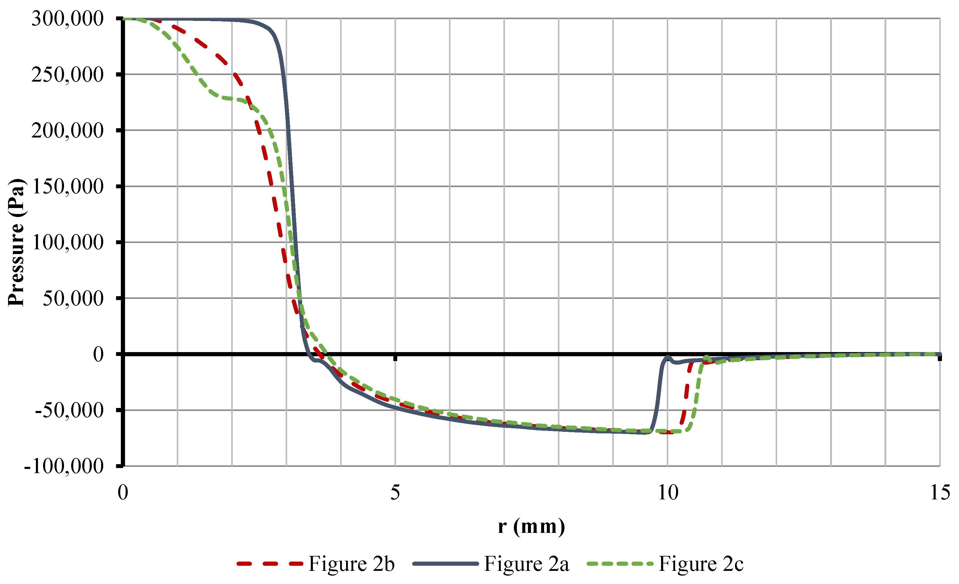
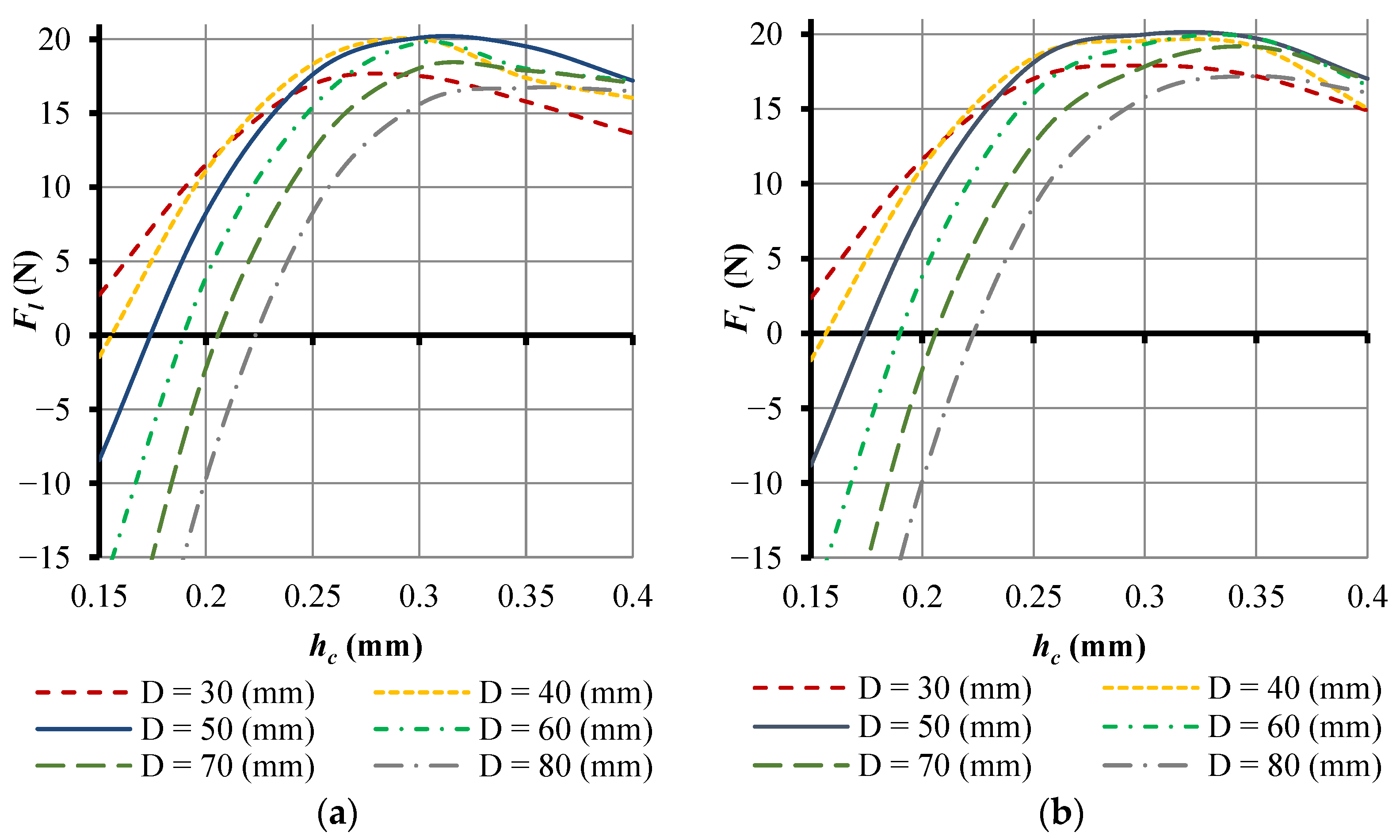
  • In the nozzle area, as the height of the gap increases, the resistance with which the air comes into contact when it enters the gap decreases, as does the speed of air movement. Therefore, the pressure in front of the nozzle decreases with increasing gap height;
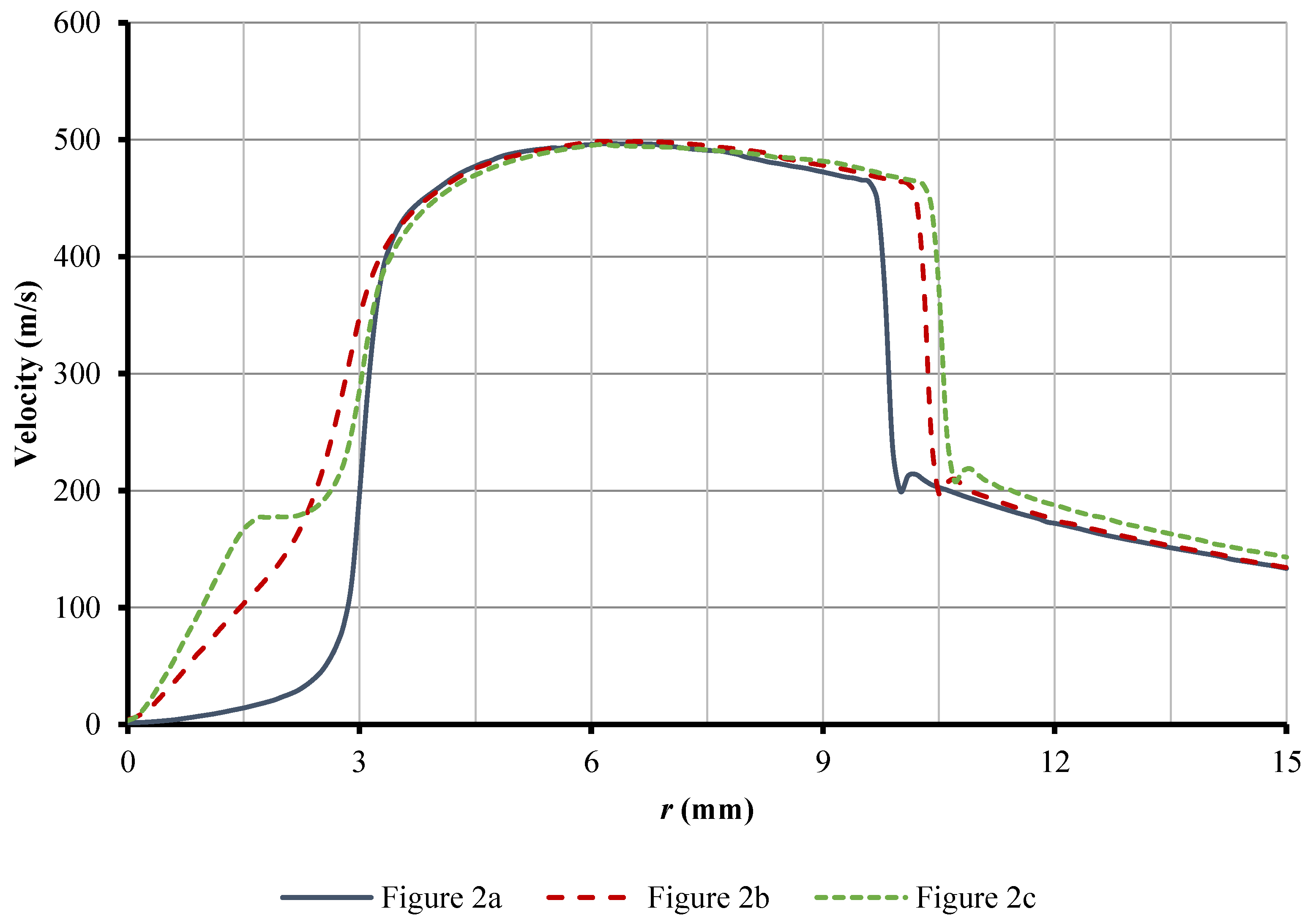
  • In the area of supersonic air velocity, increasing the height of the gap reduces the effect of narrowing the airflow, which in turn reduces the inertial effect and the effect of viscous friction. This leads to the fact that as the gap increases, the vacuum increases, but the vacuum zone decreases.
The pressure distribution varies depending on the height of the gap as well as the lifting force. The relationship between the lifting force and the height of the gap is the main characteristic of the gripping device. Figure 9 shows the obtained curves, F—h, for two designs of the Bernoulli grippers with a rounded nozzle, which are rounded.
When the gap height is small, the lifting force exhibits a negative value, indicating a repulsive force exerted on the object of manipulation. As the gap height increases, the absolute value of the repulsive force diminishes rapidly, approaching zero, and then the lifting force begins to rise. Eventually, the lifting force reaches its peak value before gradually declining. Li and Kagawa extensively discussed this trend in their paper [62]. They demonstrated that the gripper gap exhibits a coexistence of viscous and inertial effects, which stabilize each other. Consequently, when the gap height, hc, is small, the dominant effect is viscous, resulting in the Flhc curve tilting in the positive direction. On the other hand, when hc is sufficiently large, the inertial effect surpasses the viscous effect, leading to a gradual decrease in the lifting force. The transition from the region dominated by the viscous effect to the region dominated by the inertial effect gives rise to a convex curvature in the curve, representing the point of maximum lifting force. The gap height corresponding to the maximum lifting force, Fl max, is referred to as hc max.
The curve Flhc will depend on the change in the outer diameter D; Figure 10 shows the Flhc curves for grips with a range of outer diameters (D = 30, 40, 50, 60, 70, and 80 mm).
Despite variations in D, all curves exhibit a convex shape, indicating that there exists a specific gap height, hc max, for each Fl—hc curve that corresponds to the maximum lifting force. By identifying the hc max values for different outer diameters, the optimal diameter can be determined on the curved Fl—D—hc surface, as depicted in Figure 11.
As shown in Figure 11, for both grip designs (Figure 2b; Figure 2c), the lifting force Fl will be maximum in the range of outer diameters D from 40 to 60 mm. For the selected gripping parameters in two cases of the gripping design, at D = 50 mm, the widest range of the maximum lifting force Fl at change hc is provided.
Since the value of the gap between OM and BGD (hc) has the greatest impact on the gripper rate, and therefore a critical impact on the energy performance of the gripper. To determine the optimum value of the gap between OM and BGD, the so-called C—Factor [80] was selected in Figure 12. As defined by [81], the C-Factor of a gripper can be computed as the ratio of the lifting force it produces over its weight and multiply this ratio by the power. The value obtained is arguably a measure of the efficiency of the gripper and can be used for comparison between different products, designs, etc.
After analyzing the results of hc on the C—Factor for two BGD designs, it was found that the optimal gap between OM and BGD was 0.3 mm. This clearance provides maximum lifting force and minimum work spent per kilogram of lifting weight. In addition, of the two designs can be distinguished Figure 2c as the most optimal. This is due to the fact that the design of Figure 2c provides the maximum lifting force in a wider range of diameters D = 40…70 mm than Figure 2b—D = 40…60 mm. It is also important that the energy consumption of the gripper of Figure 2, c per weight gain is less than the energy consumption of the gripper of Figure 2, b by 5%. When using such gripping devices when performing automated transport operations in the workplace is quite significant.

4. Conclusions

The paper presents a mathematical model for numerically simulating the airflow dynamics in the nozzle and radial gap of a Bernoulli gripping device. Proposed modifications to the nozzle design of industrial robot Bernoulli grippers are suggested. Research findings indicate that the diameter of the smallest section of the rounded nozzle should be chosen to be 30…50% larger than the critical section area.
The use of a rounded nozzle in the Bernoulli gripping device design reduces excess pressure on the manipulated object’s surface opposite the nozzle. This improvement enhances the power characteristics of Bernoulli grippers by 40…50% while only increasing compressed air consumption by 5…9%. The outer diameter of the gripper, D, significantly influences the lifting force and is closely related to the gap height, h. Thus, the relationship between them is described using the curvilinear surface F—D—h. Optimal outer diameter parameters are determined to minimize the viscosity’s weakening effect on negative pressure, resulting in maximum lifting force. For a nozzle with a diameter of 6 mm, the optimal Bernoulli gripping device diameter is determined to be 50 mm.
The C-Factor was used to determine the optimal value of the gap height between the object to be manipulated and the Bernoulli gripping device. For a nozzle with a diameter of 6 mm, the optimal parameter of the gap height of 0.3 mm and the rational design of the nozzle of the Bernoulli gripping device are determined.
Given the primary benefit of jet grasping systems lies in their ability to minimize object damage and contact, future research will focus on developing grasping systems specifically for medical applications. These systems aim to prevent tissue damage and minimize contact, building upon the existing research conducted in this paper.

Author Contributions

Conceptualization, R.M. and A.M.F.; methodology, R.M. and F.D.; software, I.V. and A.M.F.; formal analysis, R.M. and P.J.S.; investigation, R.M. and A.M.F.; resources, R.M.; writing—original draft preparation, R.M. and A.M.F.; writing—review and editing, R.M., F.D. and I.V.; visualization, R.M. and P.J.S.; project administration, A.M.F.; funding acquisition, R.M. and F.D. All authors have read and agreed to the published version of the manuscript.

Funding

This article was written thanks to the generous support under the Operational Program Integrated Infrastructure for the project: “Research and the development of the applicability of autonomous flying vehicles in the fight against the pandemic caused by COVID-19”, Project no. 313011ATR9, co-financed by the European Regional Development Fund.

Institutional Review Board Statement

Not applicable.

Informed Consent Statement

Not applicable.

Data Availability Statement

Not applicable.

Acknowledgments

The authors would like to thank the Slovak Grant Agency—project KEGA 028STU-4/2022 and VEGA 1/0436/22 “Research on modeling methods and control algorithms of kinematically redundant mechanisms”.

Conflicts of Interest

The authors declare no conflict of interest.

References

  1. Chan, F.T.S.; Ip, R.W.L.; Lau, H. Integration of expert system with analytic hierarchy process for the design of material handling equipment selection system. J. Mater. Process. Technol. 2001, 116, 137–145. [Google Scholar] [CrossRef]
  2. Ceccarelli, M. Fundamentals of the mechanics of robots. In Fundamentals of Mechanics of Robotic Manipulation; Springer: Dordrecht, The Netherlands, 2004; pp. 73–240. [Google Scholar] [CrossRef]
  3. Shameli, E.; Khamesee, M.B.; Huissoon, J.P. Nonlinear controller design for a magnetic levitation device. Microsyst. Technol. 2007, 13, 831–835. [Google Scholar] [CrossRef]
  4. Henrich, D.; Wörn, H. Robot Manipulation of Deformable Objects; Springer Science & Business Media: Berlin/Heidelberg, Germany, 2012. [Google Scholar] [CrossRef] [Green Version]
  5. Fantoni, G.; Santochi, M.; Dini, G.; Tracht, K.; Scholz-Reiter, B.; Fleischer, J.; Hansen, H.N. Grasping devices and methods in automated production processes. CIRP Ann. 2014, 63, 679–701. [Google Scholar] [CrossRef]
  6. Fantoni, G.; Capiferri, S.; Tilli, J. Method for supporting the selection of robot grippers. Procedia CIRP 2014, 21, 330–335. [Google Scholar] [CrossRef]
  7. Li, X.; Kagawa, T. Development of a new noncontact gripper using swirl vanes. Robot. Comput.-Integr. Manuf. 2013, 29, 63–70. [Google Scholar] [CrossRef]
  8. Ozcelik, B.; Erzincanli, F.; Findik, F. Evaluation of handling results of various materials using a non-contact end-effector. Ind. Robot Int. J. 2003, 30, 363–369. [Google Scholar] [CrossRef]
  9. Savkiv, V.; Mykhailyshyn, R.; Duchon, F.; Fendo, O. Justification of design and parameters of Bernoulli–vacuum gripping device. Int. J. Adv. Robot. Syst. 2017, 14, 1729881417741740. [Google Scholar] [CrossRef] [Green Version]
  10. Savkiv, V.; Mykhailyshyn, R.; Duchon, F. Gasdynamic analysis of the Bernoulli grippers interaction with the surface of flat objects with displacement of the center of mass. Vacuum 2019, 159, 524–533. [Google Scholar] [CrossRef]
  11. Official Website of Festo AG & Co, Bernoulli Gripper OGGB. Available online: https://www.festo.com/se/en/p/bernoulli-grippers-id_OGGB/?page=0 (accessed on 23 March 2023).
  12. Official Website of SMC. Available online: https://www.smcworld.com/webcatalog/en-jp/categoryID/1036?ca_id=1036 (accessed on 23 March 2023).
  13. Official Website of Emerson. Non-Contact Transport System. Available online: https://www.emerson.com/en-us/catalog/automation-solutions/fluid-control-pneumatics/vacuum-technologies? (accessed on 23 March 2023).
  14. Official Website of Schmalz; Schmalz, J. Floating Suction Cups SBS, Special Grippers. Available online: https://www.schmalz.com/en/vacuum-technology-for-automation/vacuum-components/special-grippers/floating-suction-cups/floating-suction-cups-sbs (accessed on 23 March 2023).
  15. Mykhailyshyn, R.; Savkiv, V.; Maruschak, P.; Xiao, J. A systematic review on pneumatic gripping devices for industrial robots. Transport 2022, 37, 201–231. [Google Scholar] [CrossRef]
  16. Konishcheva, O.V.; Briukhovetskaia, E.V.; Brungardt, M.V.; Shhepin, A.N.; Kudrjavcev, I.V. Study of a swirling gas jet emanated from a vortex jet gripper onto a plain barrier. J. Phys. Conf. Ser. 2020, 1515, 042037. [Google Scholar] [CrossRef]
  17. Konischeva, O.V.; Bruhoveckaya, E.V.; Kudryavtsev, I.V. Effect of Design Features of Vortex Jet Grippers on Their Load Capacity. In Proceedings of the 6th International Conference on Industrial Engineering (ICIE 2020), Sochi, Russia, 17–21 May 2020; pp. 213–218. [Google Scholar] [CrossRef]
  18. Stühm, K.; Tornow, A.; Schmitt, J.; Grunau, L.; Dietrich, F.; Dröder, K. A novel gripper for battery electrodes based on the Bernoulli-principle with integrated exhaust air compensation. Procedia CIRP 2014, 23, 161–164. [Google Scholar] [CrossRef] [Green Version]
  19. Tanaka, Y.; Suzuki, R.; Edamura, K.; Yokota, S. Design and Fabrication of Micro Gripper Using Functional Fluid Power. Int. J. Autom. Technol. 2022, 16, 448–455. [Google Scholar] [CrossRef]
  20. Liu, D.; Liang, W.; Zhu, H.; Teo, C.S.; Tan, K.K. Development of a distributed Bernoulli gripper for ultra-thin wafer handling. In Proceedings of the 2017 IEEE International Conference on Advanced Intelligent Mechatronics (AIM), Munich, Germany, 3–7 July 2017; pp. 265–270. [Google Scholar] [CrossRef]
  21. Welanetz, L.F.; Syosset, N.Y. A suction device using air under pressure. J. Appl. Mech. Trans. Am. Soc. Mech. Eng. 1956, 78, 269. [Google Scholar] [CrossRef]
  22. Brun, X.F.; Melkote, S.N. Analysis of stresses and breakage of crystalline silicon wafers during handling and transport. Sol. Energy Mater. Sol. Cells 2009, 93, 1238–1247. [Google Scholar] [CrossRef]
  23. Brun, X.F.; Melkote, S.N. Modeling and prediction of the flow, pressure, and holding force generated by a Bernoulli handling device. J. Manuf. Sci. Eng. 2009, 131, 031018. [Google Scholar] [CrossRef]
  24. Brun, X.; Melkote, S.N. Effect of substrate flexibility on the pressure distribution and lifting force generated by a Bernoulli gripper. J. Manuf. Sci. Eng. 2012, 134, 051010. [Google Scholar] [CrossRef]
  25. Liu, D.; Teo, C.S.; Liang, W.; Tan, K.K. Soft-acting, noncontact gripping method for ultrathin wafers using distributed Bernoulli principle. IEEE Trans. Autom. Sci. Eng. 2018, 16, 668–677. [Google Scholar] [CrossRef]
  26. Wang, S.; Wang, Y.; Mei, D.; Dai, S. Development of an Annular-Shaped Bernoulli Gripper for Contactless Gripping of Large-Size Silicon Wafer. In Proceedings of the 2021 IEEE 16th International Conference on Nano/Micro Engineered and Molecular Systems (NEMS), Xiamen, China, 25–29 April 2021; pp. 1871–1876. [Google Scholar] [CrossRef]
  27. Giesen, T.; Bürk, E.; Fischmann, C.; Gauchel, W.; Zindl, M.; Verl, A. Advanced gripper development and tests for automated photovoltaic wafer handling. Assem. Autom. 2013, 33, 334–344. [Google Scholar] [CrossRef]
  28. Mykhailyshyn, R.; Savkiv, V.; Boyko, I.; Prada, E.; Virgala, I. Substantiation of Parameters of Friction Elements of Bernoulli Grippers with a Cylindrical Nozzle. Int. J. Manuf. Mater. Mech. Eng. (IJMMME) 2021, 11, 17–39. [Google Scholar] [CrossRef]
  29. Li, X.; Kagawa, T. Theoretical and experimental study of factors affecting the suction force of a Bernoulli gripper. J. Eng. Mech. 2014, 140, 04014066. [Google Scholar] [CrossRef]
  30. Ozcelik, B.; Erzincanli, F. A non-contact end-effector for the handling of garments. Robotica 2002, 20, 447–450. [Google Scholar] [CrossRef]
  31. Dini, G.; Fantoni, G.; Failli, F. Grasping leather plies by Bernoulli grippers. CIRP Ann. 2009, 58, 21–24. [Google Scholar] [CrossRef]
  32. Failli, F.; Dini, G. An innovative approach to the automated stacking and grasping of leather plies. CIRP Ann. 2004, 53, 31–34. [Google Scholar] [CrossRef]
  33. Erzincanli, F.; Sharp, J.M.; Erhal, S. Design and operational considerations of a non-contact robotic handling system for non-rigid materials. Int. J. Mach. Tools Manuf. 1998, 38, 353–361. [Google Scholar] [CrossRef]
  34. Davis, S.; Gray, J.O.; Caldwell, D.G. An end effector based on the Bernoulli principle for handling sliced fruit and vegetables. Robot. Comput.-Integr. Manuf. 2008, 24, 249–257. [Google Scholar] [CrossRef]
  35. Petterson, A.; Ohlsson, T.; Caldwell, D.G.; Davis, S.; Gray, J.O.; Dodd, T.J. A Bernoulli principle gripper for handling of planar and 3D (food) products. Ind. Robot Int. J. 2010, 37, 518–526. [Google Scholar] [CrossRef]
  36. Diahovchenko, I.; Mykhailyshyn, R.; Danylchenko, D.; Shevchenko, S. Rogowsky coil applications for power measurement under non-sinusoidal field conditions. Energetika 2019, 65, 14–20. [Google Scholar] [CrossRef]
  37. Mykhailyshyn, R.; Savkiv, V.; Fey, A.M.; Xiao, J. Gripping Device for Textile Materials. IEEE Trans. Autom. Sci. Eng. 2022. [Google Scholar] [CrossRef]
  38. McIlwraith, L.; Christie, A. Contactless Handling of Objects. U.S. Patent 6,601,888, 5 August 2003. [Google Scholar]
  39. Shi, K.; Li, X. Experimental and theoretical study of dynamic characteristics of Bernoulli gripper. Precis. Eng. 2018, 52, 323–331. [Google Scholar] [CrossRef]
  40. Savkiv, V.; Mykhailyshyn, R.; Fendo, O.; Mykhailyshyn, M. Orientation modeling of Bernoulli gripper device with off-centered masses of the manipulating object. Procedia Eng. 2017, 187, 264–271. [Google Scholar] [CrossRef]
  41. Savkiv, V.; Mykhailyshyn, R.; Duchon, F.; Mikhalishin, M. Modeling of Bernoulli gripping device orientation when manipulating objects along the arc. Int. J. Adv. Robot. Syst. 2018, 15, 1729881418762670. [Google Scholar] [CrossRef]
  42. Savkiv, V.; Mykhailyshyn, R.; Maruschak, P.; Kyrylovych, V.; Duchon, F.; Chovanec, Ľ. Gripping devices of industrial robots for manipulating offset dish antenna billets and controlling their shape. Transport 2021, 36, 63–74. [Google Scholar] [CrossRef]
  43. Mykhailyshyn, R.; Xiao, J. Influence of inlet parameters on power characteristics of Bernoulli gripping devices for industrial robots. Appl. Sci. 2022, 12, 7074. [Google Scholar] [CrossRef]
  44. Mykhailyshyn, R.; Duchoň, F.; Mykhailyshyn, M.; Majewicz Fey, A. Three-Dimensional Printing of Cylindrical Nozzle Elements of Bernoulli Gripping Devices for Industrial Robots. Robotics 2022, 11, 140. [Google Scholar] [CrossRef]
  45. Savkiv, V.; Mykhailyshyn, R.; Duchon, F.; Mikhalishin, M. Energy efficiency analysis of the manipulation process by the industrial objects with the use of Bernoulli gripping devices. J. Electr. Eng. 2017, 68, 496–502. [Google Scholar] [CrossRef] [Green Version]
  46. Savkiv, V.; Mykhailyshyn, R.; Duchon, F.; Maruschak, P.; Prentkovskis, O. Substantiation of Bernoulli grippers parameters at non-contact transportation of objects with a displaced center of mass. In Transport Means 2018: Proceedings of the 22nd International Scientific Conference, Trakai, Lithuania, 3–5 October 2018; Kaunas University of Technology: Kaunas, Lithuania, 2018; pp. 3–5. [Google Scholar]
  47. Liu, H.; Li, X.; Ma, Q.; Feng, W. Development non-contact gripper with flowrate-amplification using Coanda ejector. Vacuum 2021, 187, 110108. [Google Scholar] [CrossRef]
  48. Zhang, W.; Hong, J.; Ahmed, S.; Ounaies, Z.; Frecker, M. A Two-Stage Optimization Procedure for the Design of an EAP-Actuated Soft Gripper. In Proceedings of the International Design Engineering Technical Conferences and Computers and Information in Engineering Conference, Anaheim, CA, USA, 18–21 August 2019; Volume 59247, p. V05BT07A051. [Google Scholar] [CrossRef]
  49. Stupin, S.A.; Ogorodnikova, O.M. Topology optimization in designing of anthropomorphic gripper for a robot. In Proceedings of the AIP Conference Proceedings, Ekaterinburg, Russia, 18–22 May 2020; Volume 2313, p. 040011. [Google Scholar] [CrossRef]
  50. Sang, L.; Wang, H.; Tian, Y. Analysis, Design and Experimental Research of a Novel Bilateral Patient Transfer Robot. Machines 2022, 10, 33. [Google Scholar] [CrossRef]
  51. Li, P.; Yun, Z.; Gao, K.; Si, L.; Du, X. Design and Test of a Force Feedback Seedling Pick-Up Gripper for an Automatic Transplanter. Agriculture 2022, 12, 1889. [Google Scholar] [CrossRef]
  52. Ouyang, F.; Guan, Y.; Yu, C.; Yang, X.; Cheng, Q.; Chen, J.; Zhao, J.; Zhang, Q.; Guo, Y. An Optimization Design Method of Rigid-Flexible Soft Fingers Based on Dielectric Elastomer Actuators. Micromachines 2022, 13, 2030. [Google Scholar] [CrossRef]
  53. Stojiljković, D.; Milošević, M.; Ristić-Durrant, D.; Nikolić, V.; Pavlović, N.T.; Ćirić, I.; Ivačko, N. Simulation, Analysis, and Experimentation of the Compliant Finger as a Part of Hand-Compliant Mechanism Development. Appl. Sci. 2023, 13, 2490. [Google Scholar] [CrossRef]
  54. Batsuren, K.; Yun, D. Soft Robotic Gripper with Chambered Fingers for Performing In-Hand Manipulation. Appl. Sci. 2019, 9, 2967. [Google Scholar] [CrossRef] [Green Version]
  55. Bharanidaran, R.; Ramesh, T. A modified post-processing technique to design a compliant based microgripper with a plunger using topological optimization. Int. J. Adv. Manuf. Technol. 2017, 93, 103–112. [Google Scholar] [CrossRef]
  56. Liu, Y.; Luo, C.; Zong, W.; Huang, X.; Ma, L.; Lian, G. Optimization of Clamping and Conveying Device for Sunflower Oil Combine Harvester Header. Agriculture 2021, 11, 859. [Google Scholar] [CrossRef]
  57. Li, Z.; Yao, S.; Yun, F.; Wang, X.; Wang, L.; Wu, Y. Simulation and Optimization of the Nozzle Section Geometry for a Suspension Abrasive Water Jet. Machines 2022, 10, 3. [Google Scholar] [CrossRef]
  58. Ma, L.; Yan, H.; Ren, Y.; Li, L.; Cai, C. Numerical Investigation of Flow Force and Cavitation Phenomenon in the Pilot Stage of Electrical-Hydraulic Servo Valve under Temperature Shock. Machines 2022, 10, 423. [Google Scholar] [CrossRef]
  59. Chen, L.; Cheng, M.; Cai, Y.; Guo, L.; Gao, D. Design and Optimization of High-Pressure Water Jet for Coal Breaking and Punching Nozzle Considering Structural Parameter Interaction. Machines 2022, 10, 60. [Google Scholar] [CrossRef]
  60. Wang, G.; Yang, Y.; Wang, C.; Shi, W.; Li, W.; Pan, B. Effect of Nozzle Outlet Shape on Cavitation Behavior of Submerged High-Pressure Jet. Machines 2022, 10, 4. [Google Scholar] [CrossRef]
  61. Kamensky, K.M.; Hellum, A.M.; Mukherjee, R. Power Scaling of Radial Outflow: Bernoulli Pads in Equilibrium. J. Fluids Eng. 2019, 141, 101201. [Google Scholar] [CrossRef]
  62. Shi, K.; Li, X. Optimization of outer diameter of Bernoulli gripper. Exp. Therm. Fluid Sci. 2016, 77, 284–294. [Google Scholar] [CrossRef]
  63. Liu, D.; Wang, M.; Fang, N.; Cong, M.; Du, Y. Design and tests of a non-contact Bernoulli gripper for rough-surfaced and fragile objects gripping. Assem. Autom. 2020, 40, 735–743. [Google Scholar] [CrossRef]
  64. Yu, X.; Zhao, J.; Li, X. Optimization of mechanical performance of a Bernoulli gripper based on the force characteristic curve synthesis method. Ind. Robot 2022, 49, 1169–1177. [Google Scholar] [CrossRef]
  65. Snegiryov, A.Y. High-Performance Computing in Technical Physics. In Numerical Simulation of Turbulent Flows; Polytechnic University Publ.: St. Petersburg, Russia, 2009. [Google Scholar]
  66. Cant, S. High-performance computing in computational fluid dynamics: Progress and challenges. Philos. Trans. R. Soc. Lond. Ser. A Math. Phys. Eng. Sci. 2002, 360, 1211–1225. [Google Scholar] [CrossRef]
  67. Amundson, J.; Macridin, A.; Spentzouris, P. High-Performance Computing Modeling Advances Accelerator Science for High-Energy Physics. Comput. Sci. Eng. 2014, 16, 32–41. [Google Scholar] [CrossRef]
  68. Alfonsi, G. On direct numerical simulation of turbulent flows. Appl. Mech. Rev. 2011, 64, 020802. [Google Scholar] [CrossRef]
  69. Kajishima, T.; Taira, K.; Kajishima, T.; Taira, K. Numerical simulation of turbulent flows. In Computational Fluid Dynamics: Incompressible Turbulent Flows; Springer: Cham, Switzerland, 2017; pp. 207–235. [Google Scholar] [CrossRef]
  70. Martell, M.B.; Perot, J.B.; Rothstein, J.P. Direct numerical simulations of turbulent flows over superhydrophobic surfaces. J. Fluid Mech. 2009, 620, 31–41. [Google Scholar] [CrossRef] [Green Version]
  71. Garbaruk, A.V. Modern Approaches to Modeling Turbulence; Polytechnic University Publ.: St. Petersburg, Russia, 2016. [Google Scholar]
  72. Malikov, Z.M.; Madaliev, M.E. Numerical Simulation of Turbulent Flows Based on Modern Turbulence Models. Comput. Math. Math. Phys. 2022, 62, 1707–1722. [Google Scholar] [CrossRef]
  73. Aubin, J.; Fletcher, D.F.; Xuereb, C. Modeling turbulent flow in stirred tanks with CFD: The influence of the modeling approach, turbulence model and numerical scheme. Exp. Therm. Fluid Sci. 2004, 28, 431–445. [Google Scholar] [CrossRef] [Green Version]
  74. Menter, F.R. Two-equation eddy-viscosity turbulence models for engineering applications. AIAA J. 1994, 32, 1598–1605. [Google Scholar] [CrossRef] [Green Version]
  75. Menter, F.R.; Smirnov, P.E.; Liu, T.; Avancha, R. A one-equation local correlation-based transition model. Flow Turbul. Combust. 2015, 95, 583–619. [Google Scholar] [CrossRef]
  76. Zhang, J.; Fu, S. An efficient approach for quantifying parameter uncertainty in the SST turbulence model. Comput. Fluids 2019, 181, 173–187. [Google Scholar] [CrossRef]
  77. Hu, P.; Li, Y.; Han, Y.; Cai, S.C.; Xu, X. Numerical simulations of the mean wind speeds and turbulence intensities over simplified gorges using the SST k-ω turbulence model. Eng. Appl. Comput. Fluid Mech. 2016, 10, 359–372. [Google Scholar] [CrossRef] [Green Version]
  78. Li, X.; Li, N.; Tao, G.; Liu, H.; Kagawa, T. Experimental comparison of Bernoulli gripper and vortex gripper. Int. J. Precis. Eng. Manuf. 2015, 16, 2081–2090. [Google Scholar] [CrossRef]
  79. Wagner, M.; Chen, X.; Nayyerloo, M.; Wang, W.; Chase, J.G. A novel wall climbing robot based on Bernoulli effect. In Proceedings of the 2008 IEEE/ASME International Conference on Mechtronic and Embedded Systems and Applications, Beijing, China, 12–15 October 2008; IEEE: Piscataway, NJ, USA, 2008; pp. 210–215. [Google Scholar] [CrossRef]
  80. Birglen, L.; Schlicht, T. A statistical review of industrial robotic grippers. Robot. Comput.-Integr. Manuf. 2018, 49, 88–97. [Google Scholar] [CrossRef]
  81. Wolf, A.; Schunk, H.A. Grippers in Motion: The Fascination of Automated Handling Tasks; Carl Hanser Verlag GmbH Co. KG: Munich, Germany, 2018. [Google Scholar] [CrossRef] [Green Version]
Figure 1. Constructive scheme of Bernoulli gripping device.
Machines 11 00667 g001
Figure 2. Schemes of radial flow grippers with various forms of nozzles: (a) classic cylindrical nozzle (b) rounded cylindrical nozzle (c) rounded cylindrical nozzle with a chamfer.
Machines 11 00667 g002
Figure 3. Mesh grid of final elements of airflow: (a) hc = 0.15 mm (b) hc = 0.35 mm.
Machines 11 00667 g003
Figure 4. Boundary conditions for airflow model.
Machines 11 00667 g004
Figure 5. Schedules of distribution of pressure upon surfaces of objects of manipulation for various options of design of BGD.
Machines 11 00667 g005
Figure 6. Schedules of change of average flow rate in radial gap.
Machines 11 00667 g006
Figure 7. The influence of the height of the gap hc on the velocity and air pressure in the gap between OM and BGD for Figure 2b.
Machines 11 00667 g007
Figure 8. The pressure distribution on the surface of the OM at different gap heights hc and designs: (a) Figure 2b; (b) Figure 2c.
Machines 11 00667 g008
Figure 9. Influence of the height of the gap hc between OM and BGD on the lifting force of BGD of two designs with a rounded nozzle (D = 50 mm, rn = 3 mm, d0 = 2.5 mm, n = 0.2 mm, p = 300 kPa).
Machines 11 00667 g009
Figure 10. Influence of the height of the gap hc between OM and BGD on the lifting force of BGD at its different diameters (rn = 3 mm, d0 = 2.5 mm, n = 0.2 mm, p = 300 kPa) and designs: (a) Figure 2b; (b) Figure 2c.
Machines 11 00667 g010
Figure 11. Fl—D—hc surfaces for two BGD designs (rn = 3 mm, d0 = 2.5 mm, n = 0.2 mm, p = 300 kPa): (a) Figure 2b; (b) Figure 2c.
Machines 11 00667 g011
Figure 12. Influence of hc on C—Factor for two BGD designs (D = 50 mm, rn = 3 mm, d0 = 2.5 mm, n = 0.2 mm, p = 300 kPa).
Machines 11 00667 g012
Disclaimer/Publisher’s Note: The statements, opinions and data contained in all publications are solely those of the individual author(s) and contributor(s) and not of MDPI and/or the editor(s). MDPI and/or the editor(s) disclaim responsibility for any injury to people or property resulting from any ideas, methods, instructions or products referred to in the content.

