Article

Investigation of the Uncoordinated Bolt Deformation of a Disc–Drum Combined Structure in a Turbine under Various Operating Conditions

School of Aeronautics, Northwestern Polytechnical University, 127 Friendship West Road, Xi’an 710072, China
*
Author to whom correspondence should be addressed.
Machines 2023, 11(6), 661; https://doi.org/10.3390/machines11060661
Submission received: 24 April 2023 / Revised: 30 May 2023 / Accepted: 15 June 2023 / Published: 19 June 2023
(This article belongs to the Section Turbomachinery)

Abstract

:
At high speeds and under large axial forces, the disc–drum combined structure exhibits inconsistent deformation between parts. The difference in the structural characteristics of different parts, the speed, the preload, and its distribution mode, along with other factors, make the deformation of parts more complex, resulting in the deformation of parts during work; this deformation inconsistency has a direct impact on the engine performance. This paper presents a systemic investigation of the uncoordinated bolt deformation of an aeroengine. The finite element model of the disc–drum combined structure is established using Ansys workbench, where the deformation is uncoordinated. On this basis, the influence of different preload forces and various rotation speeds on the deformation discordance of the combined structure are discussed. Then, the relationship between the bolt deformation and component deformation incompatibility is obtained through a comprehensive analysis of the bolt deformation. A set of detailed analyses was carried out to investigate the uncoordinated deformation caused by the uneven distribution of the preload force.

1. Introduction

The disc–drum combined structure in a turbine is an important part of the high-pressure rotor, which operates at high temperatures, high pressures, and high speeds. This structure is fixed by a set of bolts between its parts, which directly influence its operating stability and that of the aeroengine. The factors that affect the bolting of the turbine disc–drum combined structure are complex; they include the preload of the bolts, the axial tension of the high-pressure turbine disc, and the centrifugal force during motion [1]. These factors evidently influence the deformation and internal stress dissonance of the interfacing parts in the turbine disc–drum combined structure. At the same time, the clearance between the assembly contact surfaces, introduced by the inevitable errors that occur during the manufacturing process, might reduce the accuracy of the bolt preload control and increase the preload error [2]. As a result, the deformation is uncoordinated. Many problems cause uncoordinated bolt deformation, resulting in the high-speed rotation of the rotor of the rabbet fit and producing an opening, cracking, and other failures. Consequently, the safety and reliability of the aeroengine are affected. Thus, engineers should carry out a series of detailed investigations on this topic.
In recent years, considerable research has been conducted into the influence of the bolt state on the disc–drum structure. To date, considerable achievements have been made in research on the dynamics of disc–drum and bolt connections. The dynamic characteristics of disc–drum structure connected with other bolt have been studied by applying the analytical method, the finite element method, and the hybrid modeling method. Wang et al. [3] investigated the variation in the connection stiffness of the disc–drum structure under the action of an external axial force and the bending moment, using the finite element approach. Panja, D. [4] used the bending moment to simulate the bolted structure and investigated the effect of the connection structure on the mechanical characteristics of the turbine rotor. Qin et al. [5] considered the frictional contact at the joint interface and discussed the effect of the bolt preload force and the rotational speed on the dynamic characteristics of the disc–drum structure. In addition, Qin et al. [6] developed an analytical model of the bending stiffness of the bolted disc–drum structure. Zou et al. [7] used a high-pressure compressor disc rotor, a high-pressure turbine disc rotor, and a high-pressure rotor system as the research objects and analyzed the mating surface using the finite element method and the experimental method. Liu et al. [8] developed a dynamic model of a disc–drum rotor system with frictional shock and analyzed the dynamic characteristics of the disc–drum rotor system. Yao et al. [9] investigated the influence of the bolt preload on the inherent characteristics, critical speed, and unbalanced response of the rotor system via a modified thin-layer unit method, and the results indicated that the bolt connection structure in the rotor system can be equated to a rigid structure. Ma et al. [10] used Ansys to simulate the bolted flange structure with a rabbet, and the results showed that the effect of the bolt preload on the bending stiffness is non-negligible. Liu, S. et al. [11] analyzed the effect law of parameters, such as bolt spacing, tightening times, and the end runout, on the rate of change of the preload force. They also suggested that the tightening process deforms the mounting edge after assembly.
Some researchers have also conducted related studies on a bolt connection structure containing a rabbet, a considerable number of which have been published. For example, Guo et al. [12] established a refined finite element model of the bolted joint surface considering the rabbet, and the experimentally obtained stiffness–deformation curves verified the accuracy of the finite element model. Gaul et al. [13] established a centralized parameter model through experimental identification, and a contact slip model was established through a finite element model; then, the two models were combined in the finite element program to analyze the dynamic response of the connected structure. Bograd et al. [14] summarized the method of connection modeling in composite structures and described the method of connection modeling based on finite elements. Boeswald, M. et al. [15] conducted a force and deformation analysis of a structure based on a rabbet and used finite elements for nonlinear contact analysis. Hong, J. et al. [16] constructed a nonlinear analytical model for the rabbet bolt connection under moment loading and revealed the nonlinear stiffness characteristics and hysteresis damping characteristics of the connection. They also analyzed the effects of the rabbet tightness and flange length on the connection damping and the equivalent stiffness of the connection structure. Venczel, M. et al. [17] used goal-driven optimization design to optimize the design of structures with rabbets, thereby promoting the coordination of the deformation of the bolted connection structure and the rationalization of the stress distribution in the bolted part. Ouyang, H. et al. [18] used the nonlinear finite element method to analyze the dynamic effects of structural parameters and external loads on the contact state; they discussed the contact state of the contact surface stress distribution at the danger point and proposed considering the effects of the rotor joint’s location, structural parameters, and external loads. Campos et al. [19] presented a simplified method to determine the radial and circumferential stresses in thin-walled cylindrical structural members with internal and external fits and summarized the mechanics of crimped joint assemblies, which inform the analysis of rabbet contact sections. Liu et al. [20] studied the stiffness characteristics of flanged joints at the rabbet based on the Ansys nonlinear transient analysis method, and hysteresis curves were drawn by using simple harmonic loads to extract displacement data. In addition, Wang et al. [21] simplified the structure of a bolted flange joint containing a rabbet by using a Jenkins unit and a spring unit in parallel; they then analyzed the slip deformation mechanism of the rabbet between the contact interfaces.
The literature indicates the relative maturity of the study of factors such as the bolt preload force, the number of bolts, and the frictional contact of the dynamic characteristics of the rotor. Moreover, the modelling methods, connection characteristics, and contact characteristics of the rabbet have been studied for a long time and a number of papers have been published on this topic. However, the influence of the bolt preload on the deformation of the rabbet at high rotational speeds and the deformations that may occur in different parts due to certain structures have not been considered. To address this problem, this study focuses on the uncoordinated deformation of the combined turbine disc–drum structure, the high-pressure turbine disc, the sealing grate disc, and the drum cylinder connection. The degrees of deformation of the rabbet and bolt under different speed conditions, as well as the different preload conditions of the bolt, are calculated using the finite element method to further analyze the working conditions and locations that may produce greater danger. This paper provides a reference for studying the deformation analysis and contact stress of the disc–drum combined structure. It has certain relevance to investigations of the parts that may wear. The relationship between different factors and the discordant deformation of components can help us to understand the deformation state between parts caused by discordant deformation, and even the serious fault of the separation of parts.

2. Configuration and Operating Conditions

2.1. Description of Structure

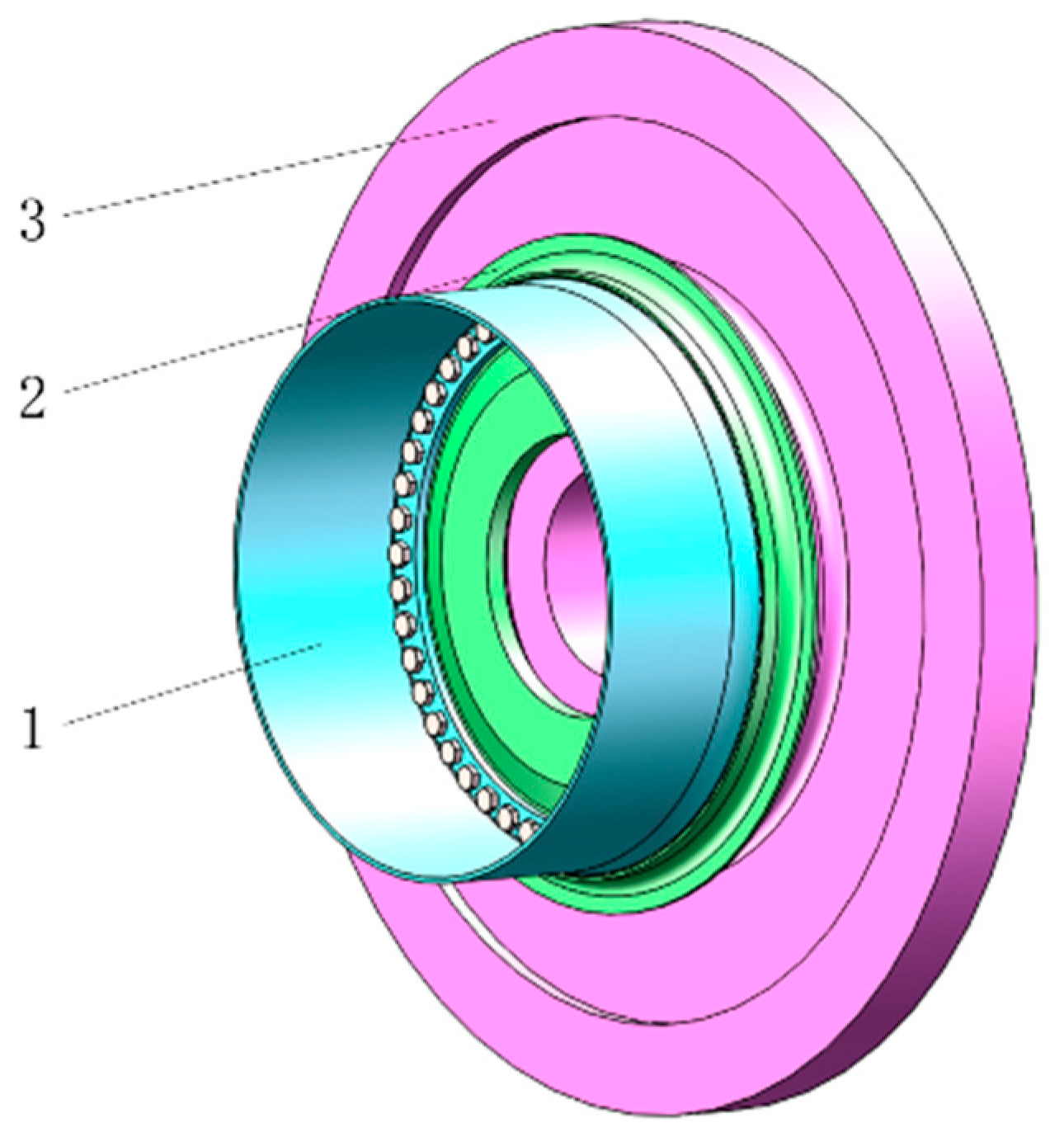
The proposed turbine disc–drum combined structure mainly consists of a drum shaft (1), a sealing grate disc (2), and a high-pressure turbine disc (3) that are assembled in series, as shown in 
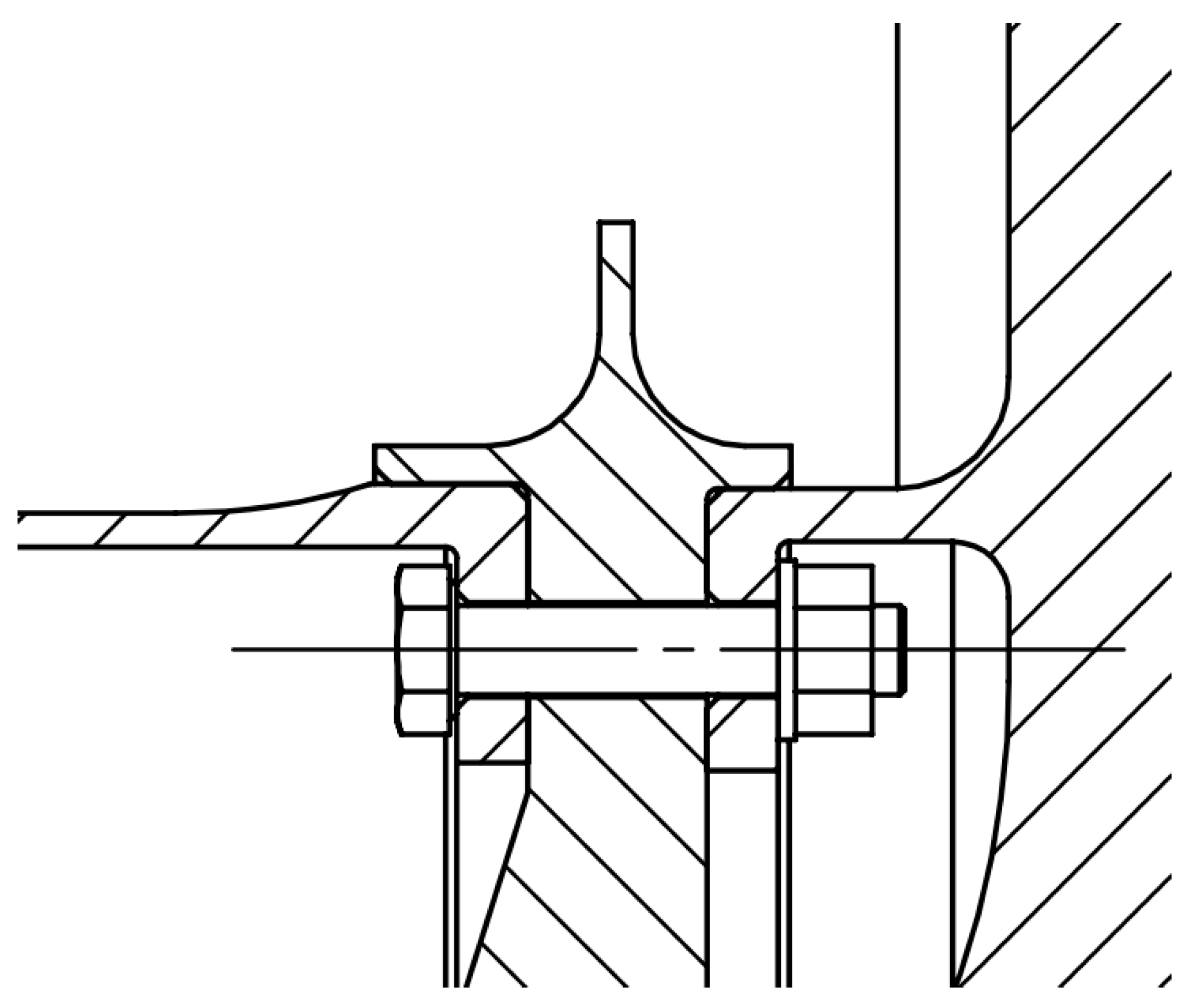
Figure 1. They contact at the rabbet position and are assembled by 48 distributed bolts, which are uniformly distributed circumferentially, fixed at the rabbet. A cross-sectional view of the bolt connection is shown in Figure 2. The contact interface connected by bolt will make the dynamic characteristics of the connecting member exhibit strong nonlinearity, complicating the dynamic characteristics of the interface between the disc–drum connection and the bolt connection [15,22].
As shown in Figure 1 and Figure 2, the high-pressure turbine disc is a disc-shaped structure with a larger overall diameter and mass on the outer ring of the disc structure, requiring a higher centrifugal force during rotation. The drum shaft is mainly a thin-walled cylindrical structure with a smaller radius of rotation, which is subject to less centrifugal force than the high-pressure turbine disc. Therefore, the drum barrel shaft and high-pressure turbine disc have different degrees of deformation in the radial direction during operation due to differences in the centrifugal force and structure. This phenomenon indicates that the high-pressure turbine disc and other parts are more prone to uncoordinated deformation at the joints.
The high-pressure turbine disc drives the drum shaft and the sealing grate tooth disc to rotate at high speeds during actual work. The maximum rotating speed can reach 18,000 rpm, and the entire structure suffers from a high-pressure working environment. Thus, the high-pressure turbine disc, drum shaft, and sealing grate disc should possess high tightening forces, indicating that the bolts must have high preloads during operation.
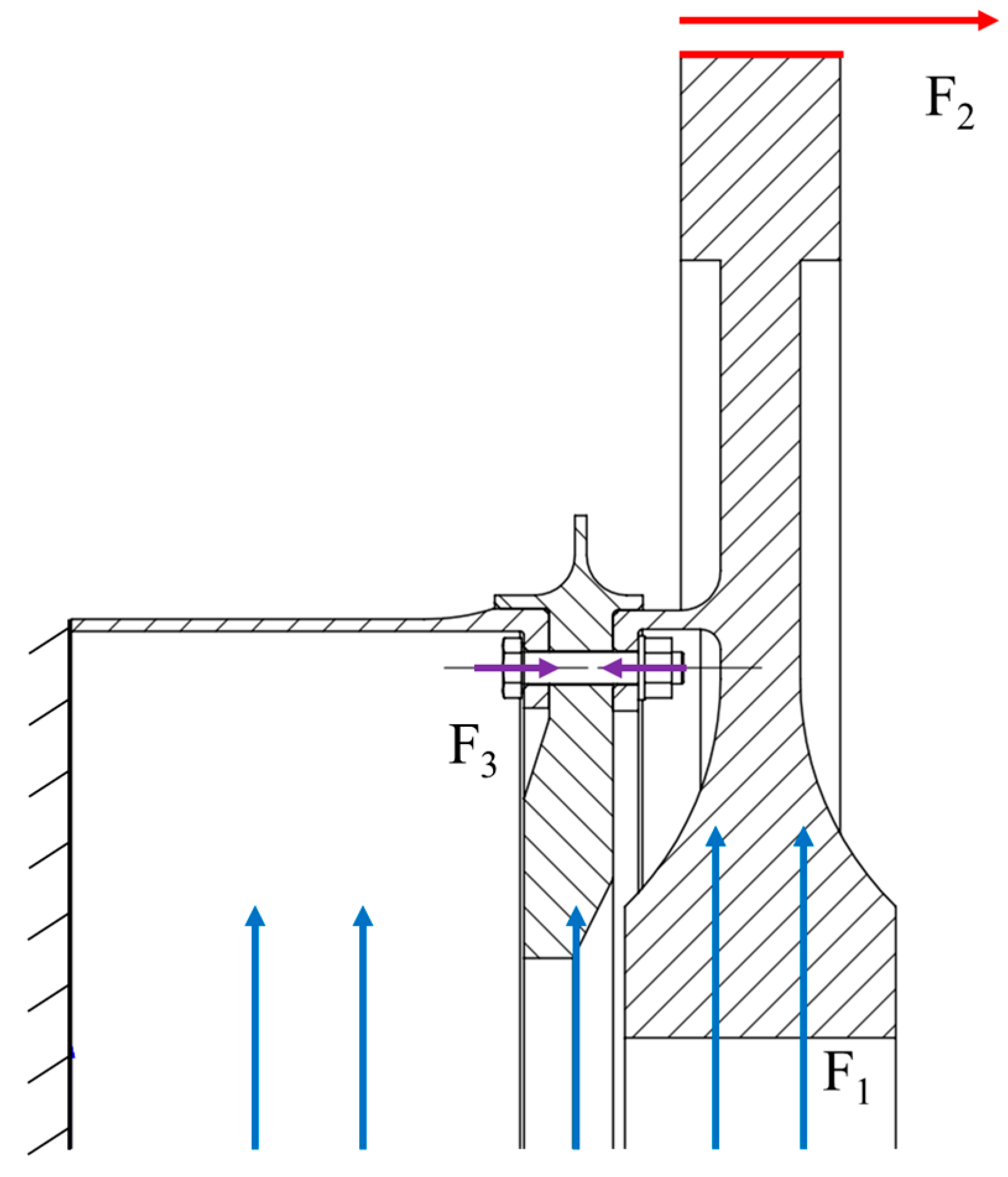
Figure 3 shows the working condition of the combined turbine disc–drum structure. A large centrifugal force F1 acts on the combined structure due to the high rotational speed. In addition, the high-pressure turbine disc is subjected to an axial aerodynamic force F2 with a value of 200 kN in the axial direction due to the high temperature and pressure of the combustion chamber gas. It is mainly carried by the bolted and interference connections. The bolt connection should have a bolt preload F3, which is generally set to a 20 kN preload in engineering practice. In actual engineering, the left side of the drum shaft is fixed on the rest of the engine. Since the results of the analysis of the left part are not considered in this paper, the left side of the drum shaft is a fixed constraint to represent the fixed connection between the drum shaft and other parts.

2.2. Finite Element Modelling

The main material of the combined turbine disc–drum structure is high-temperature alloy GH4169, which has a Poisson’s ratio of 0.33. The bolts and other connecting parts of the materials are set as structural steel. The detailed material parameters are shown in Table 1.
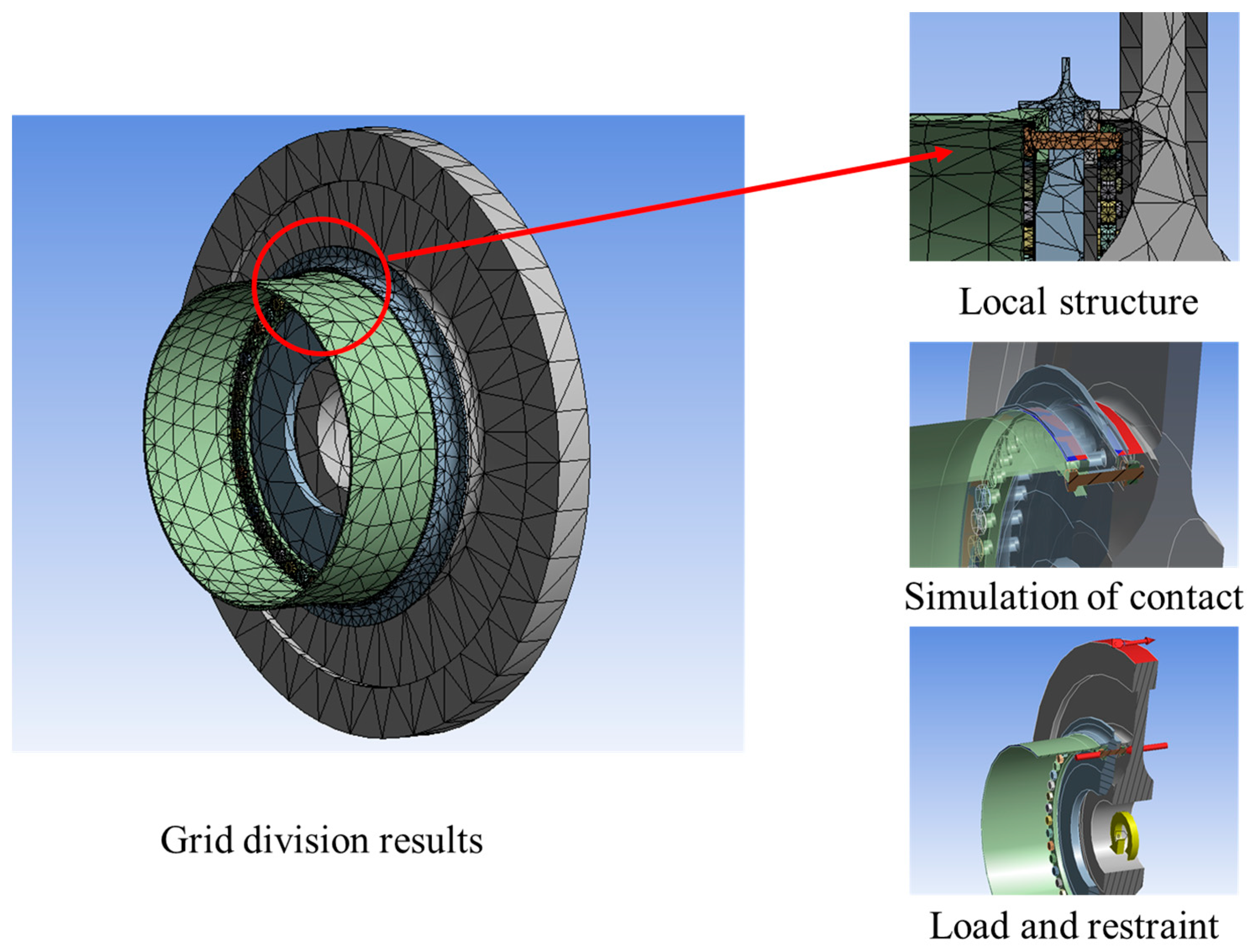
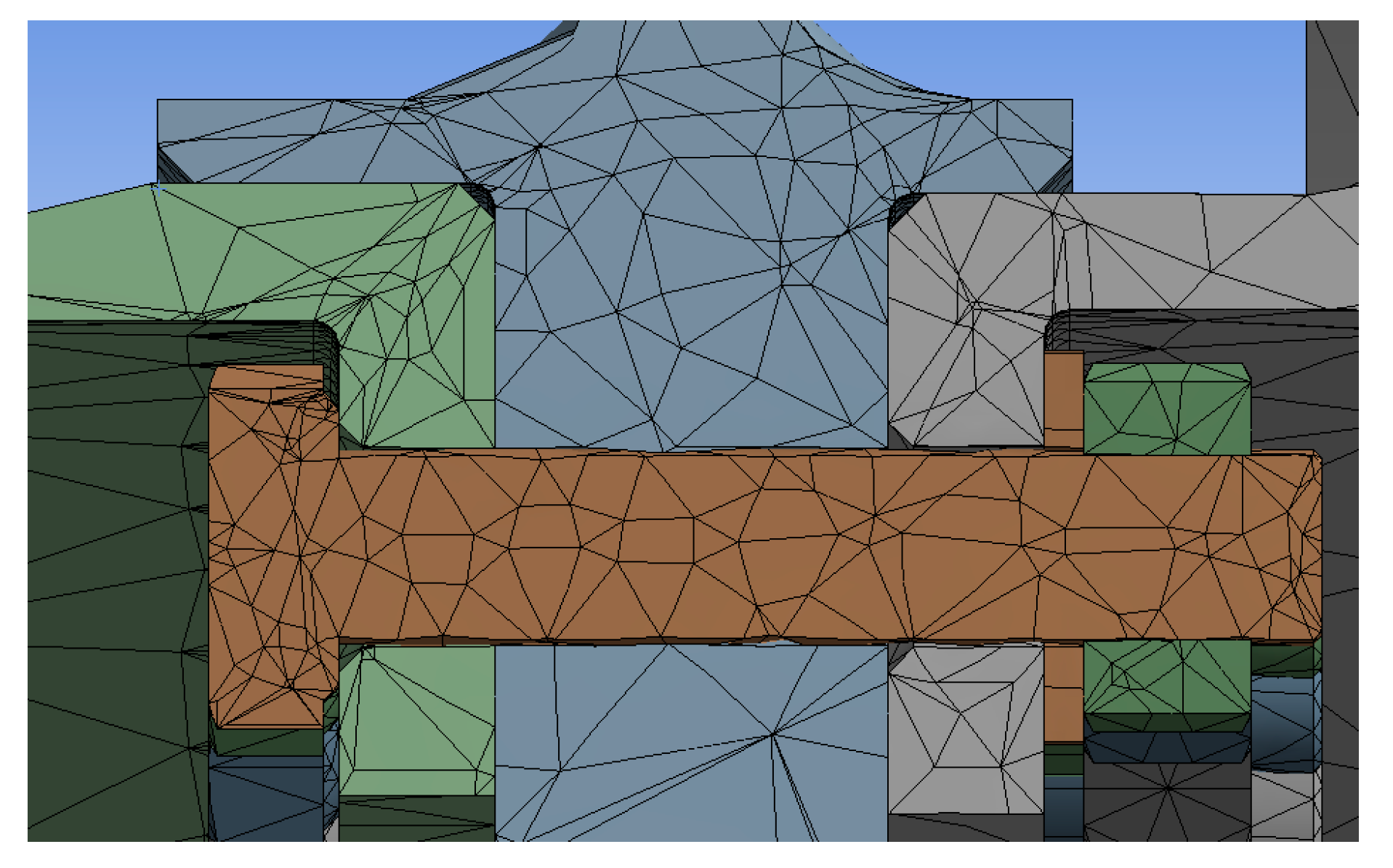
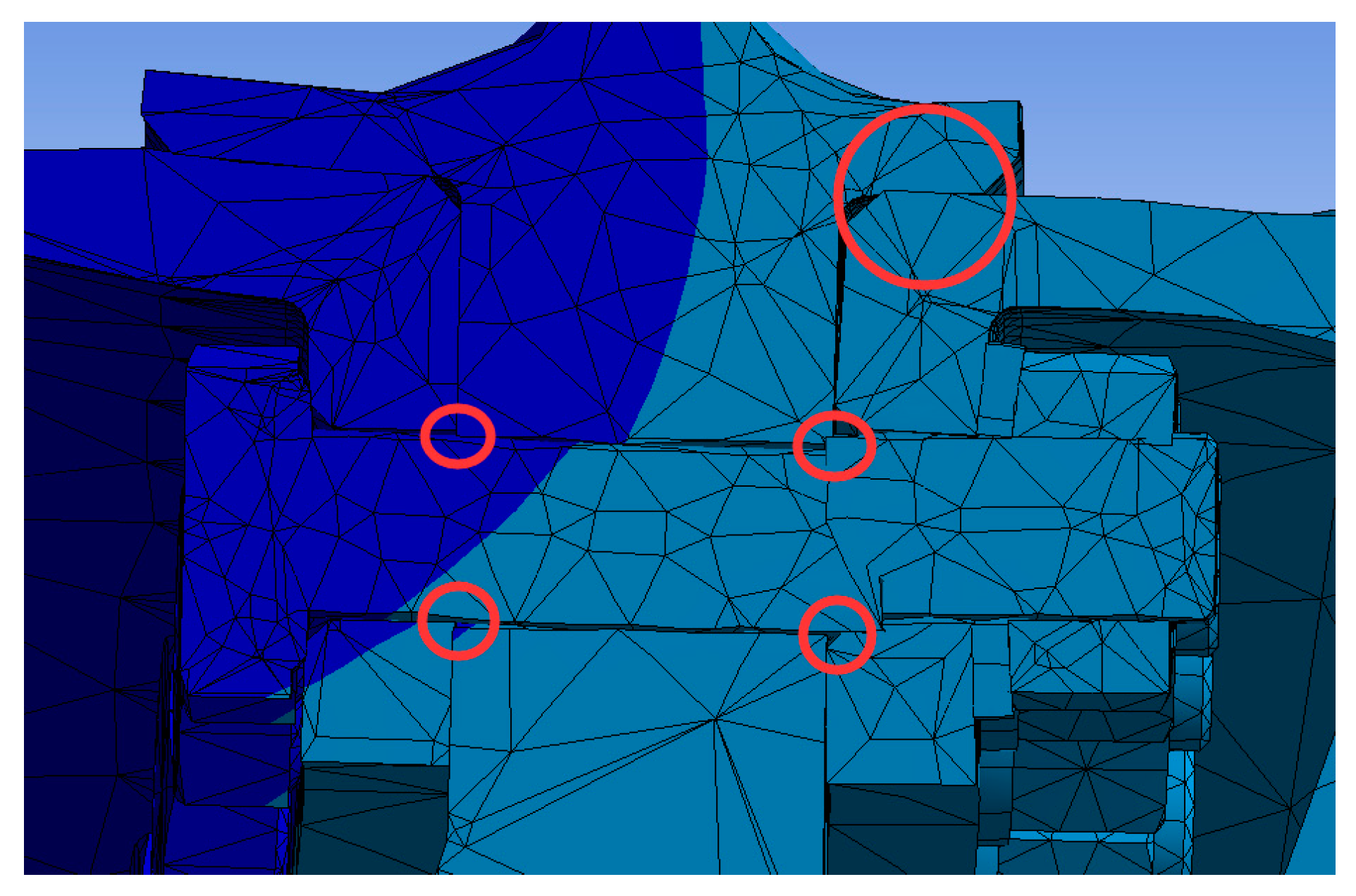
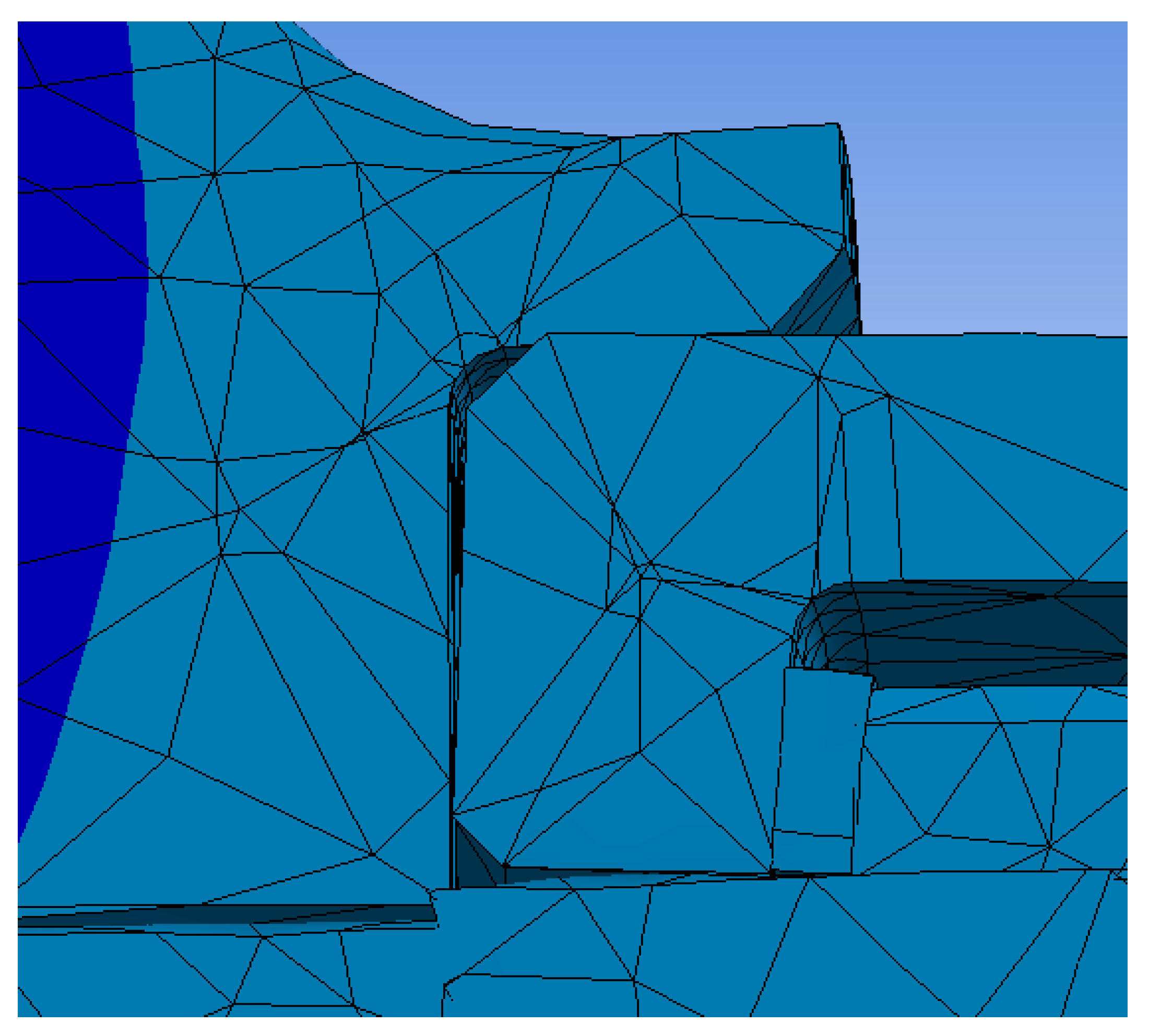
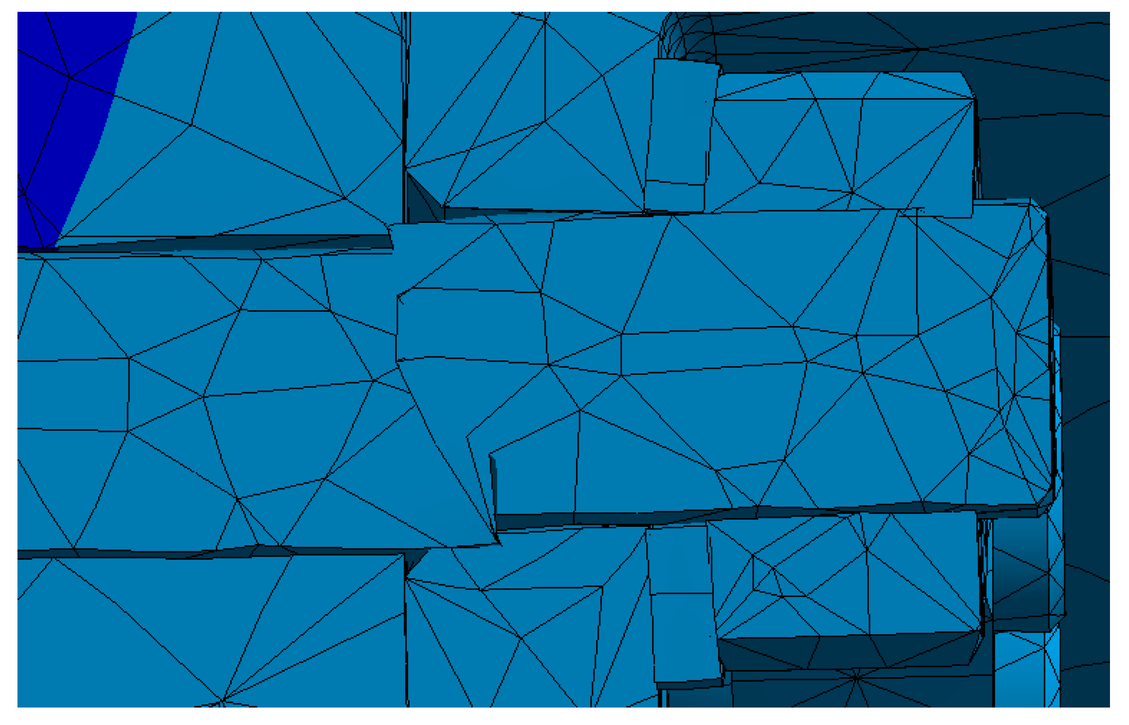
The main part of the uncoordinated deformation is the rabbet of the three components, i.e., the bolted parts and the joint surface of the three components are the key areas. The mesh is divided to refine the bolted parts and the joint surface of the three components and to simplify the high-pressure turbine disc’s surface and the drum shaft’s body. Similar calculation results are produced when meshing using Tetrahedrons, Hex, Sweep, MultiZone, and other methods. The tetrahedrons unit is chosen as the meshing unit in this paper. After meshing, 116,276 cells and 224,161 nodes are found in the finite element model, as shown in Figure 4.
The representation of the bolted connection cannot be the same as the real part because of certain interference problems. During the simulation, a simplified bolt is considered and introduced instead of the standard bolt model to simulate the displacements and stresses. The results of the study of the finite element analysis using different modelling methods for bolted connections in Ansys workbench indicated that solid cells without threads were used to simplify the bolts, without considering the threaded contact.
The uncoordinated deformation problem at the rabbet opens and closes the joint surface of the high-pressure turbine disc, sealing the grate tooth disc and drum shaft; thus, bonded contact is not achieved. The assembly relationship between the three components is an interference assembly with an interference value of 0.15 mm; thus, the joint surface of the circumference between the 3 components is set as frictional contact with a friction coefficient of 0.3, as shown in Figure 5. The three components are fastened by bolts, so bonded contact is achieved between the bolt and the drum shaft, the bolt and the nut, the gasket and the high-pressure turbine disc, and the gasket and the nut. Clearance between the bolt and the bolt hole is obtained because the bolt structure is simplified. Thus, no separation contact is observed between the bolt and the bolt hole of the three components. The behavior in the above contacts was set as ‘Auto controllers’, and the setting of trim contact is the default, namely, ‘Program Controlled’. Formation was set as ‘normal Lagrange’. Advanced options such as the detection method, penetration tolerance, and elastic slip tolerance were set as ‘Program Controlled’. The target surfaces of contact were all sealed labyrinth plates, and the contact surfaces set are shown in Figure 4.
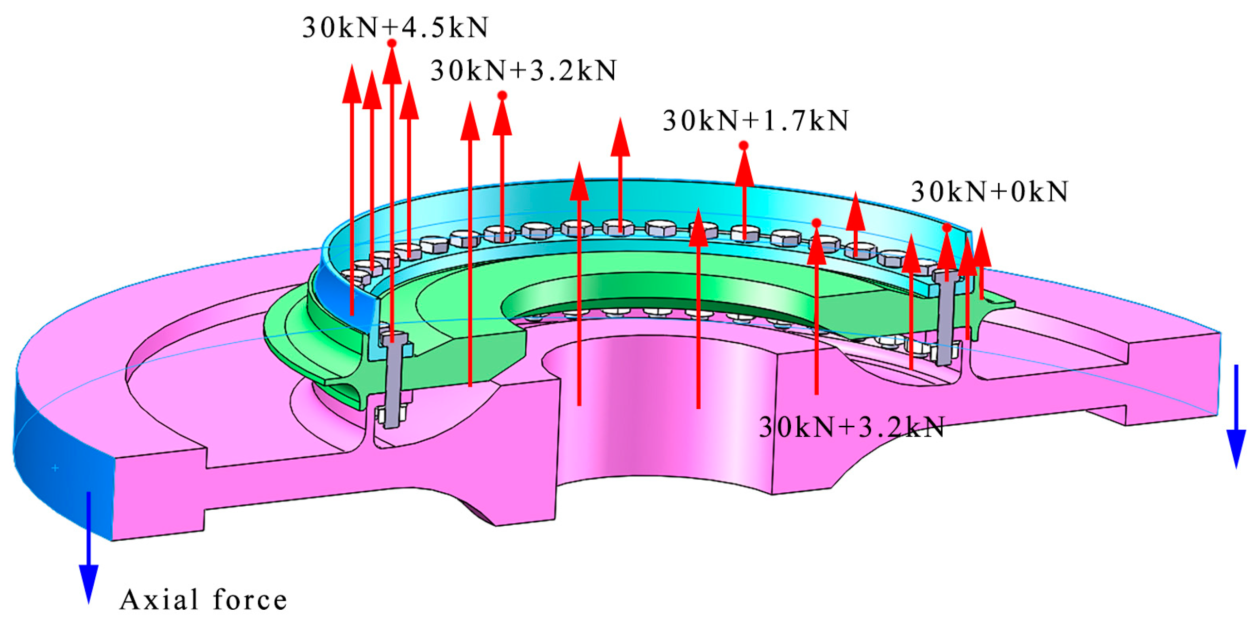
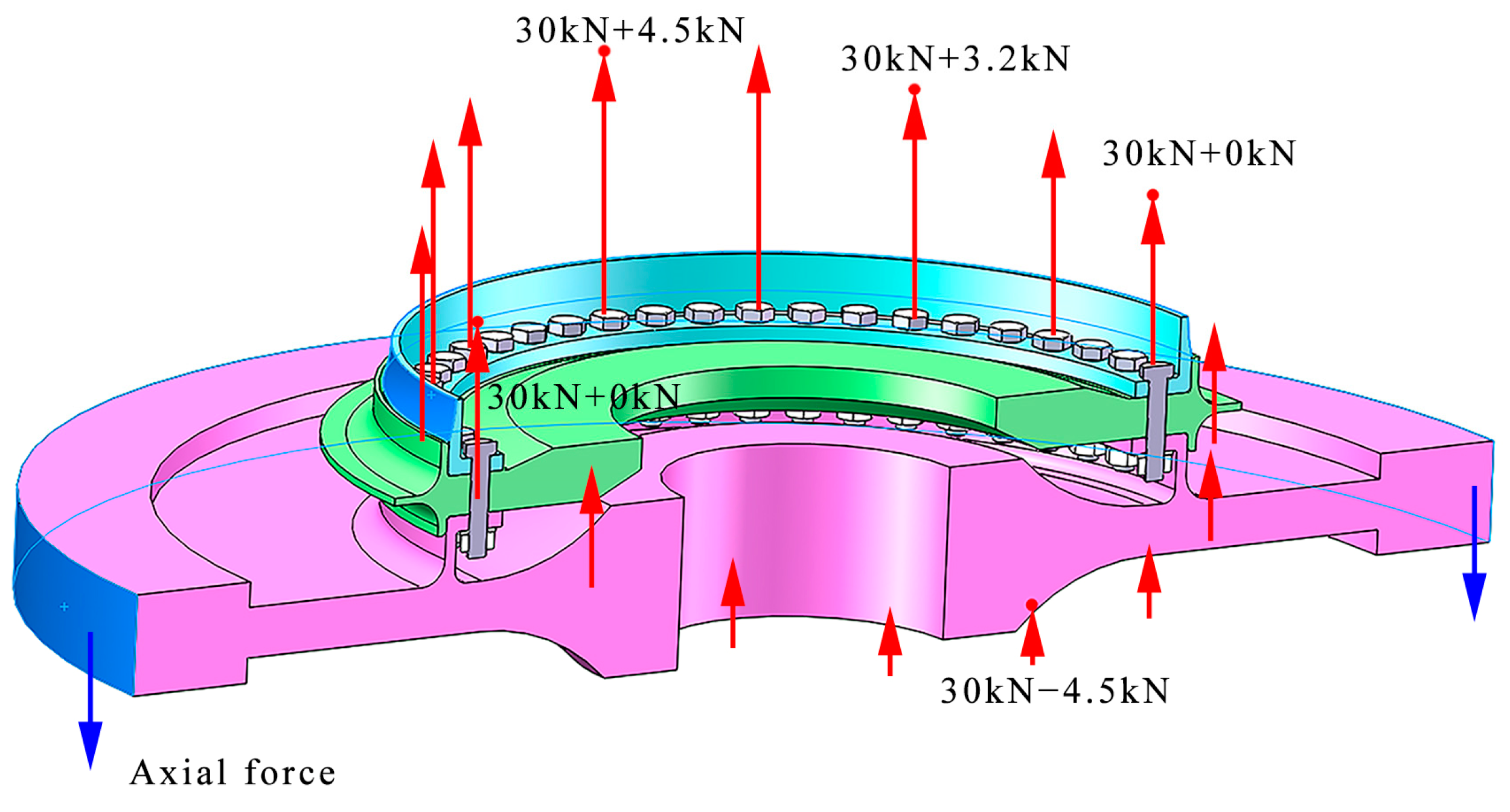
The main factors leading to uncoordinated deformation are the preload force and rotational speed. Different preload forces and rotational speeds are used to investigate their degree of influence on uncoordinated deformation. The preload force of 20 kN is generally used in engineering practice, but the preload force is either extremely large or small due to the difficulty of controlling the preload force and the unsatisfactory machining of the joint surface. In this study, three typical types of preload force are considered, namely, 10, 20, and 30 kN.
The entire operating cycle of the rotor can be divided into three stages, namely, high-, medium-, and low-speed conditions with corresponding rotational speed values of 8000, 12,000, and 18,000 rpm, respectively. Therefore, different overall angular speeds are applied to the combined structure.
The high temperatures and high-pressure gas subject the structure to an axial load of 200 kN. Thus, a force of 200 kN is applied to the high-pressure turbine disc to simulate the axial load. In the finite element model, the left side of the drum cylinder is connected to the disc, which is assumed in this study to be the ideal case without deformation, and the left side of the drum shaft is set as a fixed restraint. By adding the rotation speed to the whole turbine structure, the software can automatically calculate the centrifugal force load on the structure. Therefore, by applying different rotational speeds, different centrifugal force effects will be obtained, which then have different influences on the degree of deformation coordination of the structure.

3. Deformation and Characteristics of the Local Area Incongruity

The deformation of the combined structure is obtained by applying contacts and constraints in the finite element software according to the actual operating conditions of the engine. The main deformation areas are analyzed, and the degree of incongruity of the key points in this area is calculated to study the areas of the combined structure where the separation phenomena are most likely to occur.

3.1. Grid Independence Verification

Grid independence was verified by comparing the shape variables of grids of different sizes. The grid sizes are set as 40 mm, 30 mm, 20 mm, 10 mm, and 8 mm. The number of nodes, the number of elements, and the maximum deformation obtained by different grid sizes are shown in Table 2. The deformation results and the relationship between deformation and elements are shown in Figure 5.
The maximum error of the result value is 4.89% when the mesh is different; meanwhile, the finite element model used in this paper refines the key positions and simplifies the remaining positions, ultimately producing 116,276 elements. According to the data in the table, compared with the more refined finite element model, the error in this paper can be controlled within 1.77%, indicating that the mesh is feasible.

3.2. Deformation

3.2.1. Deformation of the Combined Structure

The bolt connection part, the high-pressure turbine disc, the drum shaft, and the seal tight grate tooth disc contact part clearly exhibit uncoordinated deformation with low speeds and low preloads. The rabbet is used as a key part to study the three-component incongruity. Figure 6 shows the deformation results.
The deformation of the rabbet is obtained at six locations that are prone to inconsistency, namely, points A, B, C, D, E, and F, as shown in Figure 7. The displacements generated at the same point on the two components during force deformation are inconsistent, and the resulting difference can represent the degree of inconsistency at that part of the two components. In this study, the deformation displacement at the corresponding point and the overall deformation are investigated for each component individually.
The rabbet before and after deformation is shown in Figure 8 and Figure 9, respectively, where the deformation schematic is located in the 50-times displacement field. The drum shaft and sealing grate disc, the high-pressure turbine disc and sealing grate disc, and the bolt and sealing grate disc interfere and separate due to uncoordinated deformation.

3.2.2. Deformation of the Parts

As shown in Figure 10, the largest deformation of the bolt appears at the end of the bolt and rod, which is the contact area between the bolt and the high-pressure turbine disc. The overall displacement diagram shows that the end of the bolt and the high-pressure turbine disc show more evident uncoordinated deformation.
Figure 11 indicates that the tail end of the bolt exhibits large displacement, resulting in an overall flared shape. The cross-sectional view shows that the entire structure appears to be deflected at a certain angle and that the degree of displacement of the high-pressure turbine disc end is larger than that of the other areas. This phenomenon is mainly due to the different degree of deformation of the assembly at the bolt connection, indicating that serious uncoordinated deformation occurs at the rabbet. Therefore, the deformation consistency between the high-pressure turbine disc and the sealing grate disc should be analyzed.
The key points are collected in the 100-times displacement field to reduce the collection error and highlight the degree of deformation. Figure 10 shows that the points on the bolts are A, B, C, and D. The points on the drum cylinder axis are A and B. The points on the sealing grate disc are A, B, C, D, E, and F. Additionally, the points on the high-pressure turbine disc are C, D, E, and F. Figure 12, Figure 13 and Figure 14 show a sectional view of the part as it deforms.

3.3. Uncoordinated Deformation

The displacement after deformation of the same point on different components is different, and the distance error can be obtained by differentiating the displacements of the same point of different components, thereby representing the degree of deformation discordance. The combination of the two components yields five comparison combinations, as shown in Table 3.
The deformation error of each combination is shown in Table 4, where a value of 1 for incongruity represents a deformation error of 0.01 mm. A comparison of the incongruity degree of each combination is shown in Figure 15, where the horizontal coordinates represent five combinations, the vertical coordinates represent the degree of incongruity of the two components, and different colors represent the points at different locations.
Figure 15 shows more points where the deformation error of the two components is larger than 1.00, indicating that the deformation error can be up to 0.01 mm. In this situation, the incongruity is serious. The locations that are more likely to produce inconsistency are the joint surfaces of the high-pressure turbine disc and the sealing grate disc, the bolt and the sealing grate disc, and the bolt and the high-pressure turbine disc. The uncoordinated deformation between the components should be considered because the bolts and bolt holes have a large clearance, and the bolts are less likely to interfere and deform with the other components. The degree of incongruity is larger at points C, E, and F in the component, and the corresponding deformation is shown in Figure 16 and Figure 17.

4. Influence of Preload and Speed on the Uncoordinated Deformation

The effect of different preload forces and different rotational speeds on the degree of uncoordinated deformation in the rabbet is analyzed, and we identify the most serious working conditions that lead to the separation of the rabbet. The relationship between the bolt deformation and the uncoordinated deformation is also analyzed by calculating the bolt deformation under different preload forces and rotational speeds.

4.1. Design of the Simulation Calculation

The deformation of the combined structure at the joint is an important factor when the entire rotor is subjected to a large centrifugal force and because the bolt preload is up to 20 kN, which also has a non-negligible effect on the deformation of the three components. Therefore, the rotational speed and preload force evidently influence the deformation.
The engine working speed includes low speeds, medium speeds, and high speeds as the three working conditions, at 8000, 12,000, and 18,000 rpm, respectively. In engineering practice, a preload force of 20 kN is generally considered. In this study, three preload force cases of 10, 20, and 30 kN are considered, because avoiding errors in setting the preload force is difficult.
The orthogonal experimental design is carried out due to the need to consider two operating conditions with different rotational speeds and preload forces at the same time. The working conditions at different rotational speeds and preload forces are divided into nine groups, as shown in Table 5.

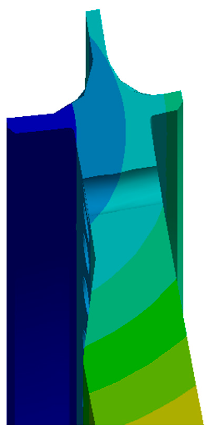
4.2. Deformation of the Rabbet

The finite element simulation of the combined structure was performed at different preload forces and speeds. Table 6 shows the deformation results of the rabbet.
For different rotational speeds and high rotating speeds, conditions are more likely to have more serious inconsistencies than for low and medium speeds. In addition, with the increase in speed, a new inconsistent key location is produced. The increase in the displacement of the tail end of the bolt with the increase in the rotational speed increases the degree of incoordination of the tail end of the bolt; it is more affected by the rotational speed than by the change in the preload.
State 3 suggests that the high speeds and insufficient preload lead to serious incoordination and a significant separation phenomenon. Therefore, the different preloads have a non-negligible effect on the change in the degree of incoordination. The preload force of different bolts is different due to machining and assembly errors. Therefore, the effect of an uneven preload on the deformation should be analyzed.
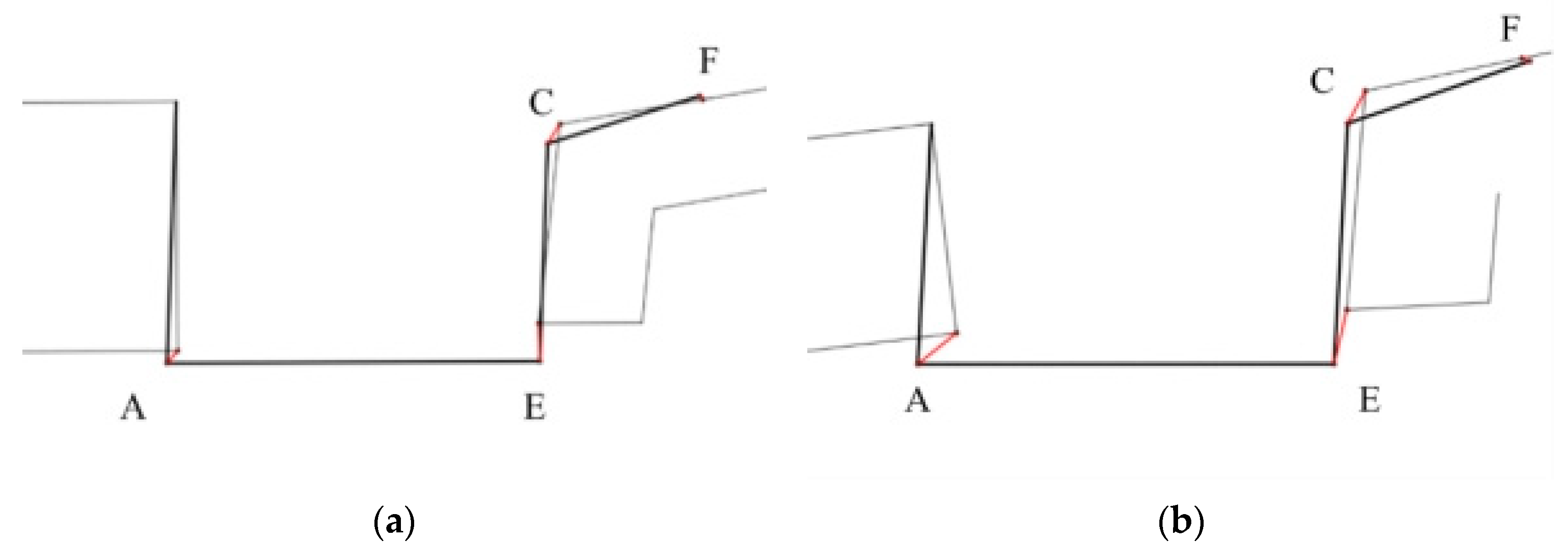
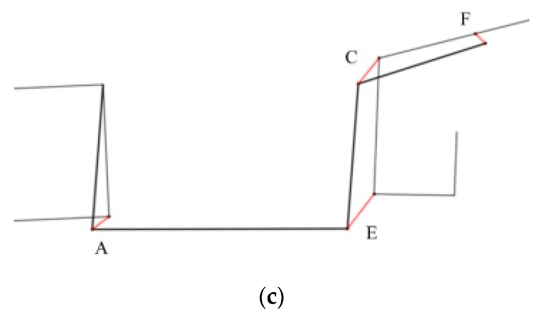
The higher degree of discordance mainly exists between the high-pressure turbine disc and the sealing grate disc, as is consistent with the analysis presented in 
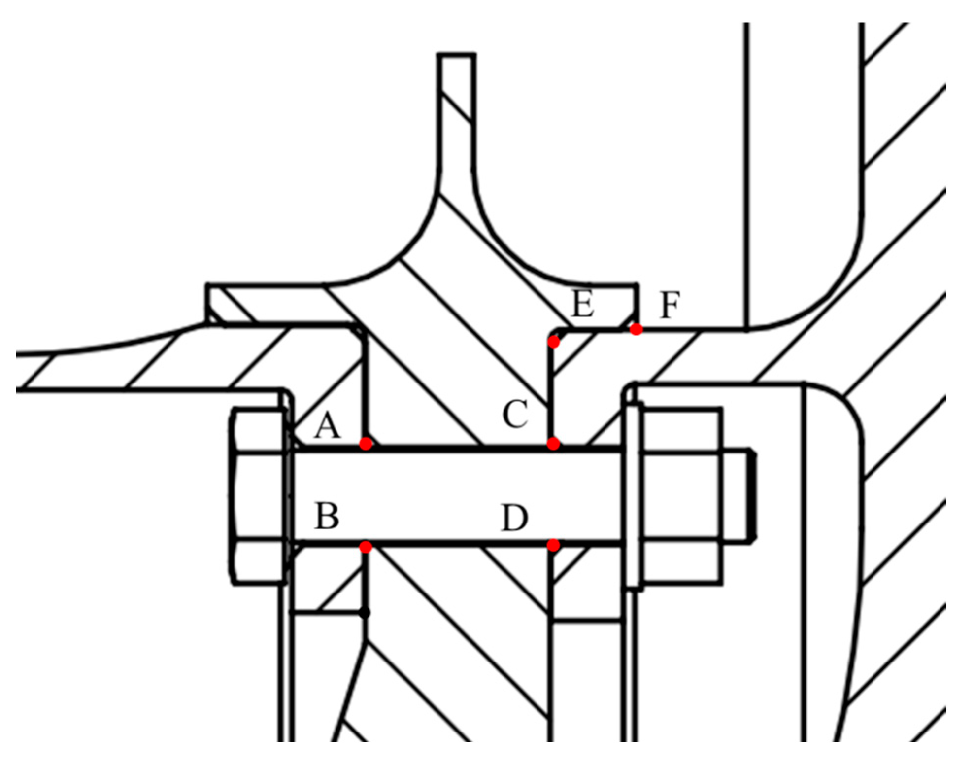
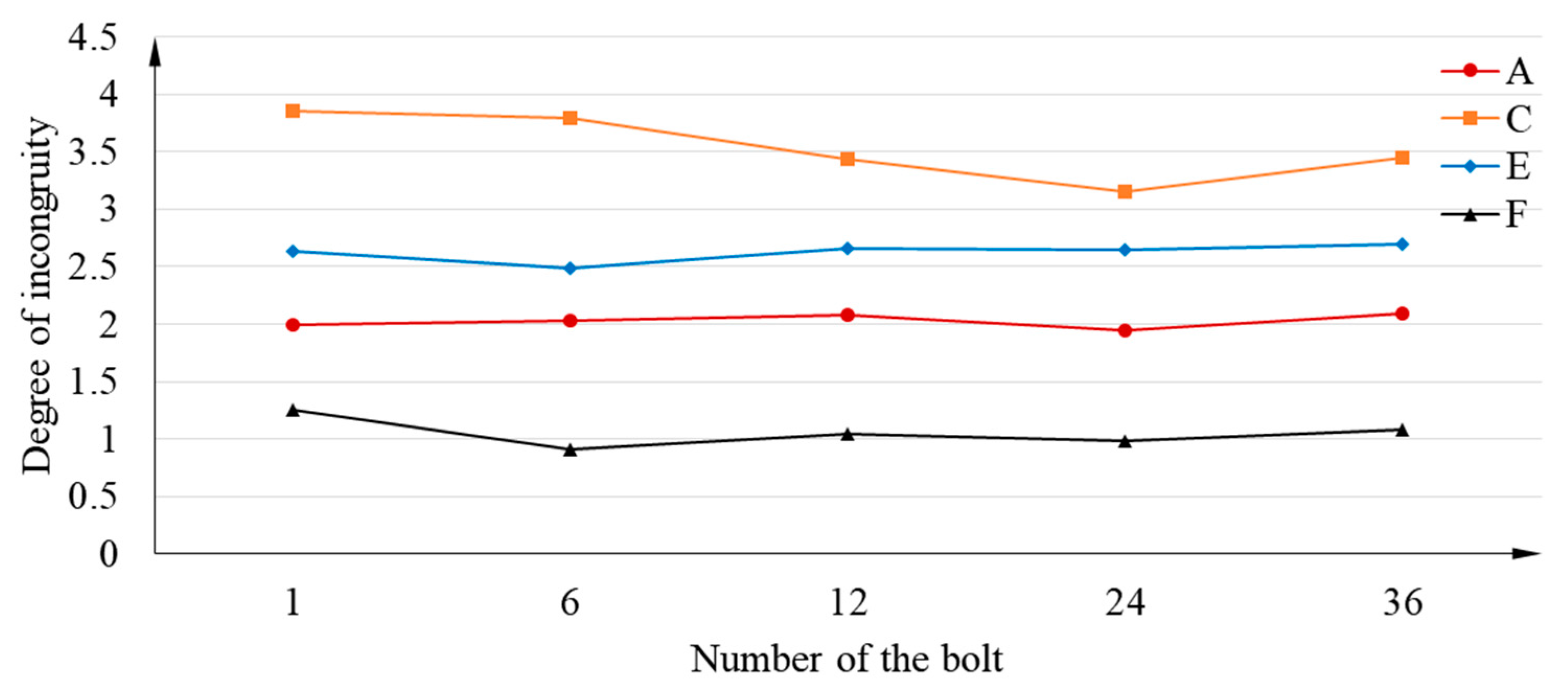
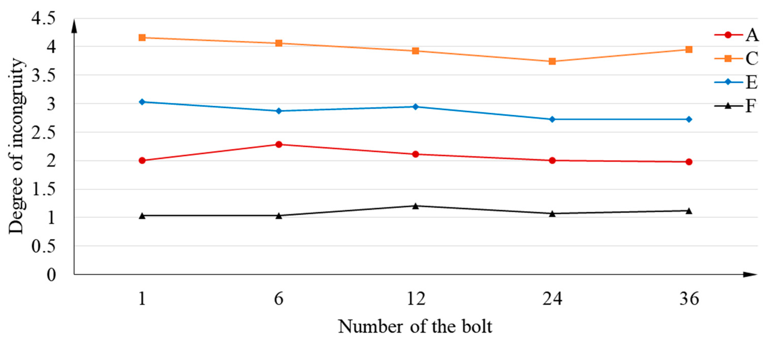
Section 3.2. In addition, the more evident discordance between the drum shaft and the sealing grate disc only occurs at higher speeds. Thus, the deformation errors of points A, C, E, and F in different states should be further counted and comparatively analyzed, as shown in Figure 10.

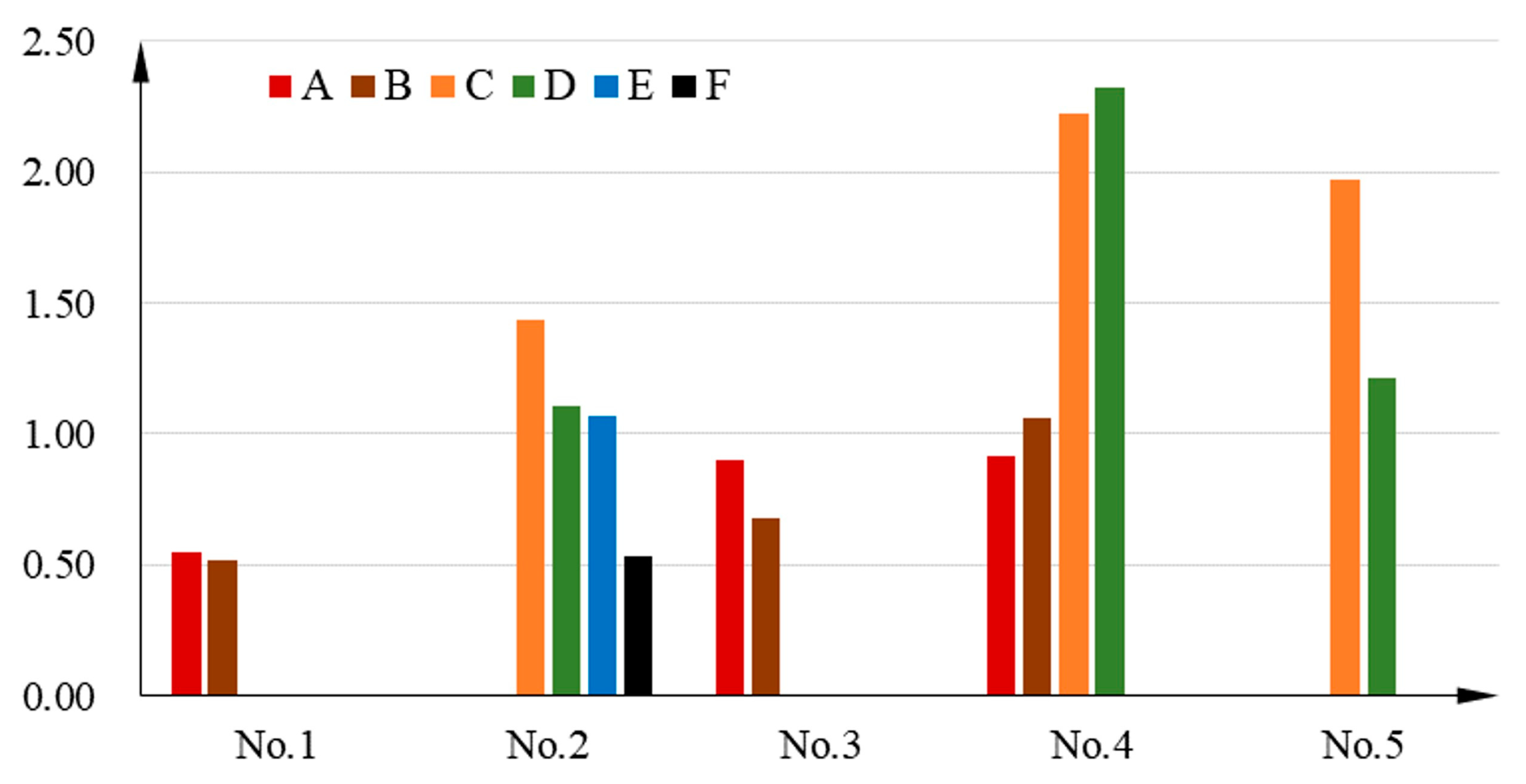
4.3. Uncoordinated Deformation of the Rabbet

The points C, E, and F appear to be deformed with larger errors and more serious separation phenomena, based on the analysis in Section 3.2. Therefore, the coordinates of points C, E, and F on the deformed drum shaft, sealing tight grate tooth disc, and high-pressure turbine disc are collected. In the case of low preloads and high speeds, point A exhibits a serious separation phenomenon; thus, the coordinates of point A are also considered for acquisition.
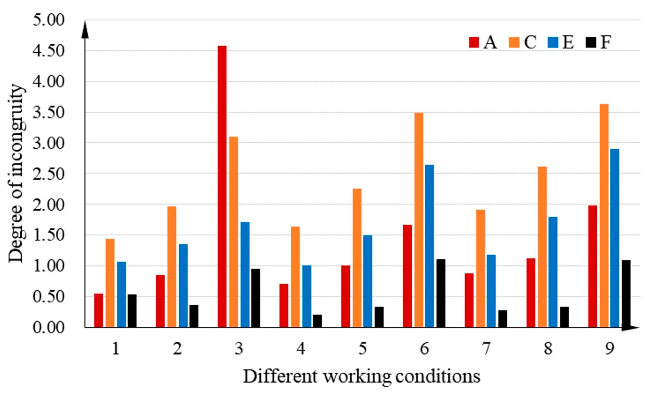
The deformation error is obtained by differentiating the position coordinates of the same point on different components, representing the degree of uncoordinated deformation. The degree of uncoordinated deformation at the four points is shown in Table 7. The comparison of the degree of uncoordinated deformation at the points of the nine states is shown in Figure 18.
The largest degree of uncoordinated deformation is situated at point C, and the degree of inconsistency at points C and E is larger than 1 for all operating conditions. This condition indicates that the deformation errors of the high-pressure turbine disc and the sealing grate disc at points C and E amount to 0.01 mm under actual operating conditions.
As shown in Figure 19, the joint surface where the uncoordinated deformation is most likely to occur is between the high-pressure turbine disc and the sealing grate disc. Moreover, the uncoordinated deformation of the drum shaft and the sealing grate disc can easily occur at high speeds when the preload is insufficient. Therefore, the preload error affects the deformation consistency of the drum shaft and the sealing grate disc.
Uncoordinated deformation is most likely to occur under high-speed and high-preload operating conditions. In addition, the change in speed has a greater influence on the degree of incoordination, whereas the preload force exerts less influence.

4.4. Deformation of the Bolt

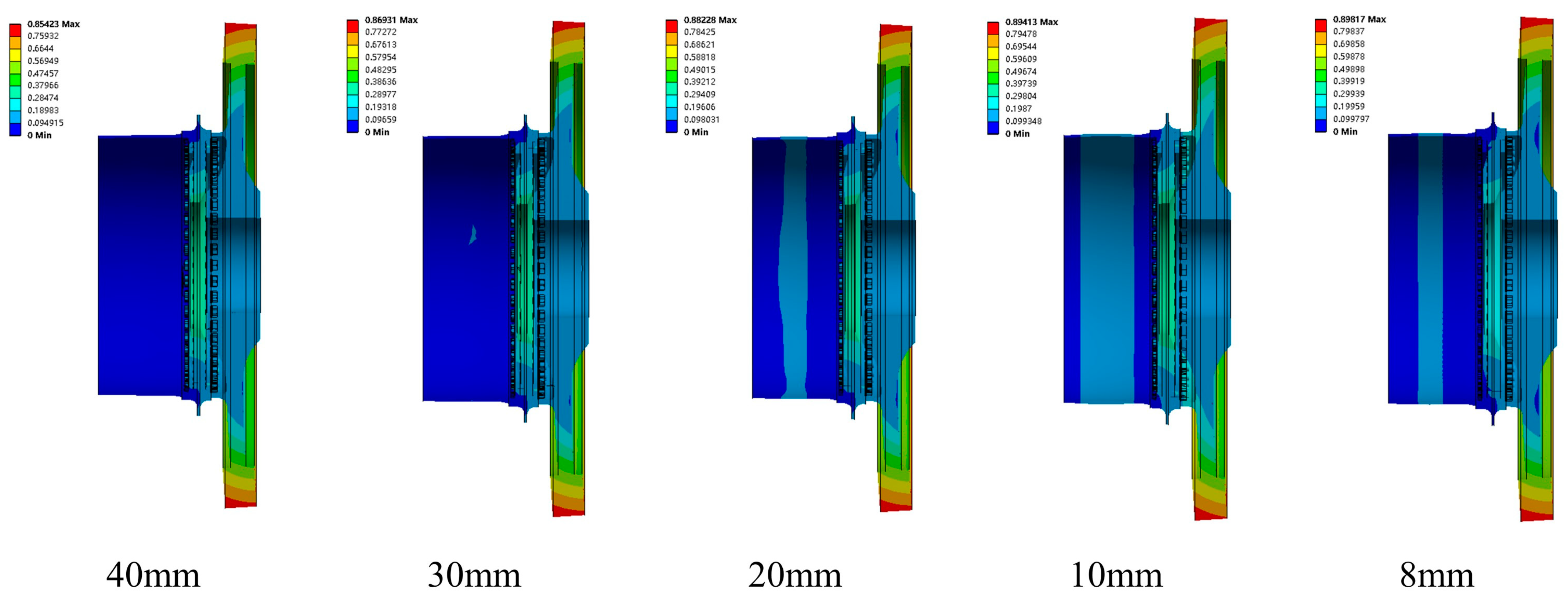
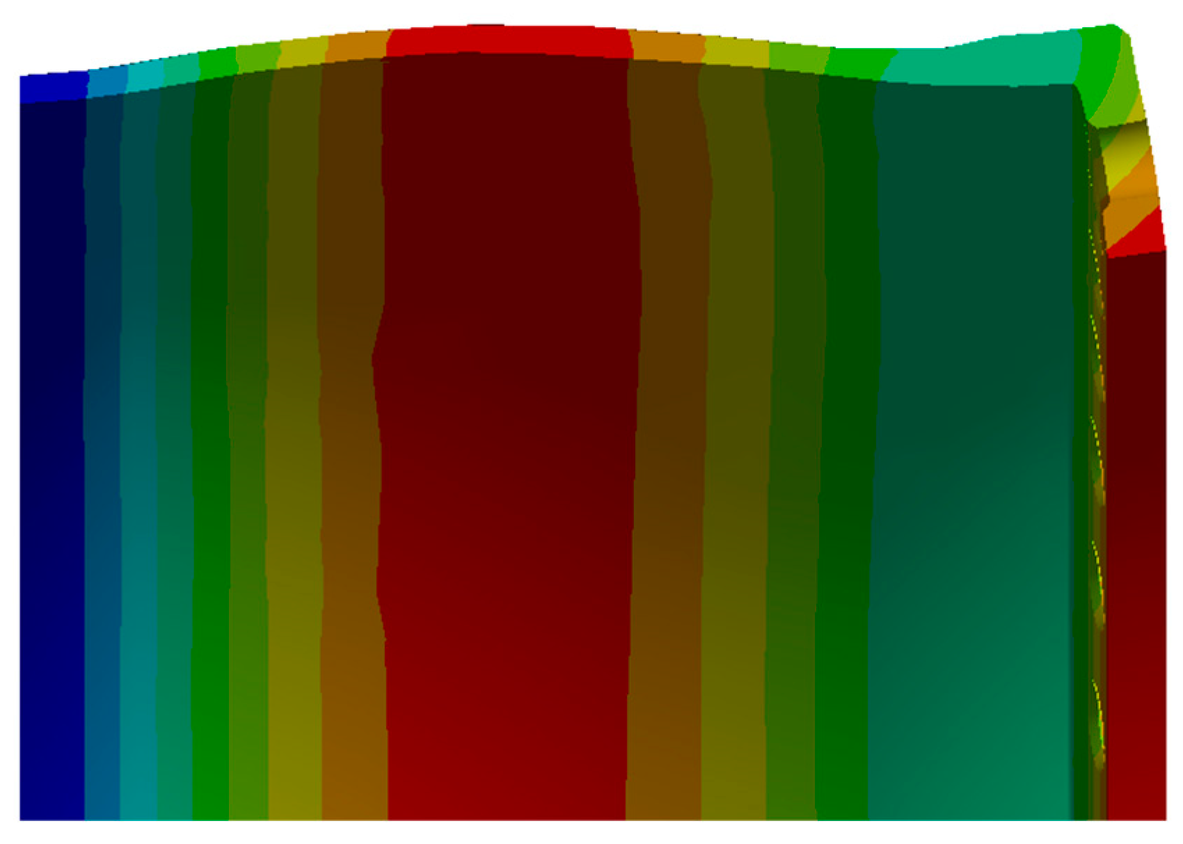
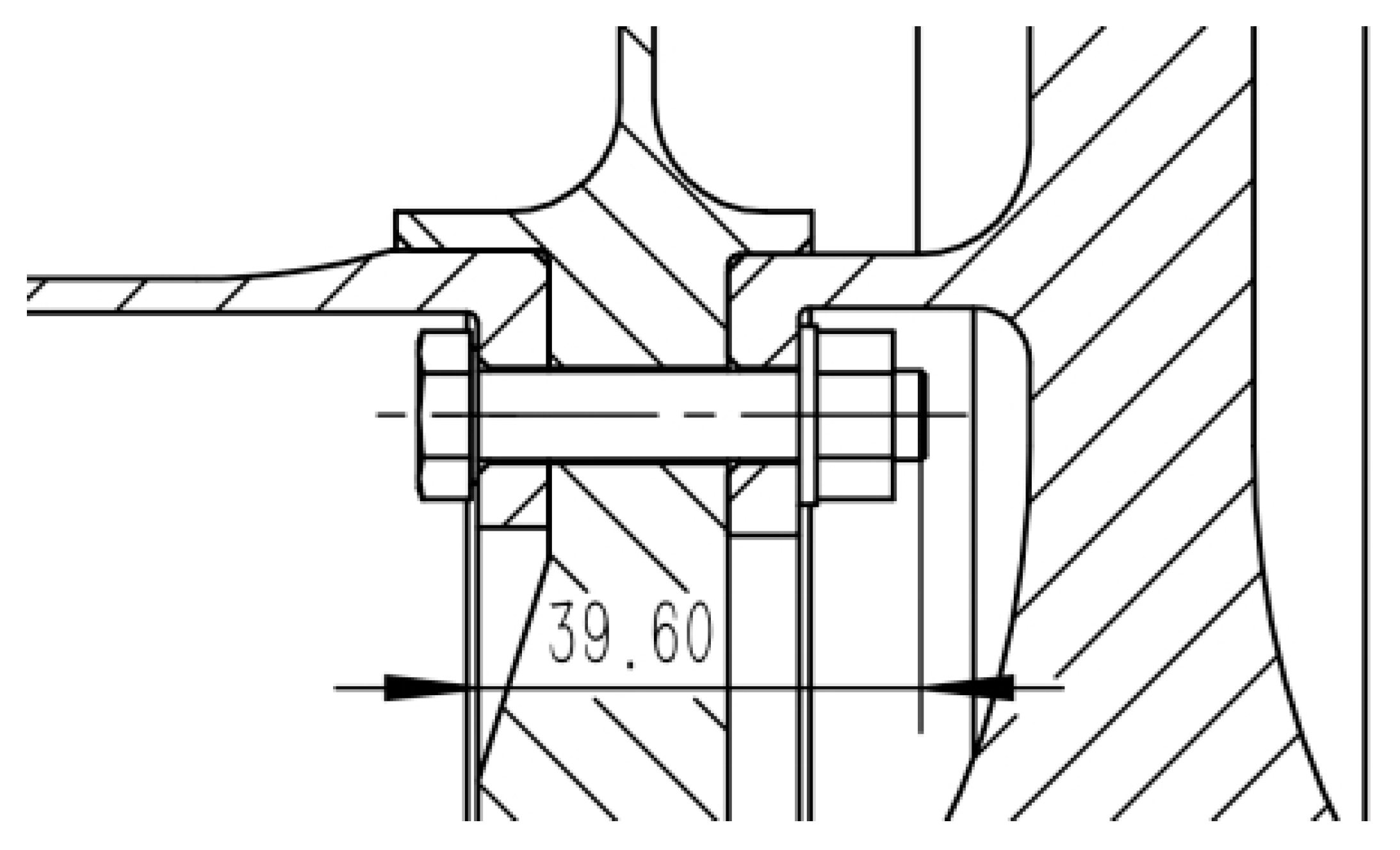
The deformation of the rabbet shows that the component separation is more serious; the main reason for this concerns the deformation of the bolt after the force. In this section, the lengths of the bolts after deformation in different states are statistically analyzed, and those under different preloads are calculated considering no rotational speed. The length of the bolt without a preload and rotational speed is L0 = 39.6 mm, as described in 
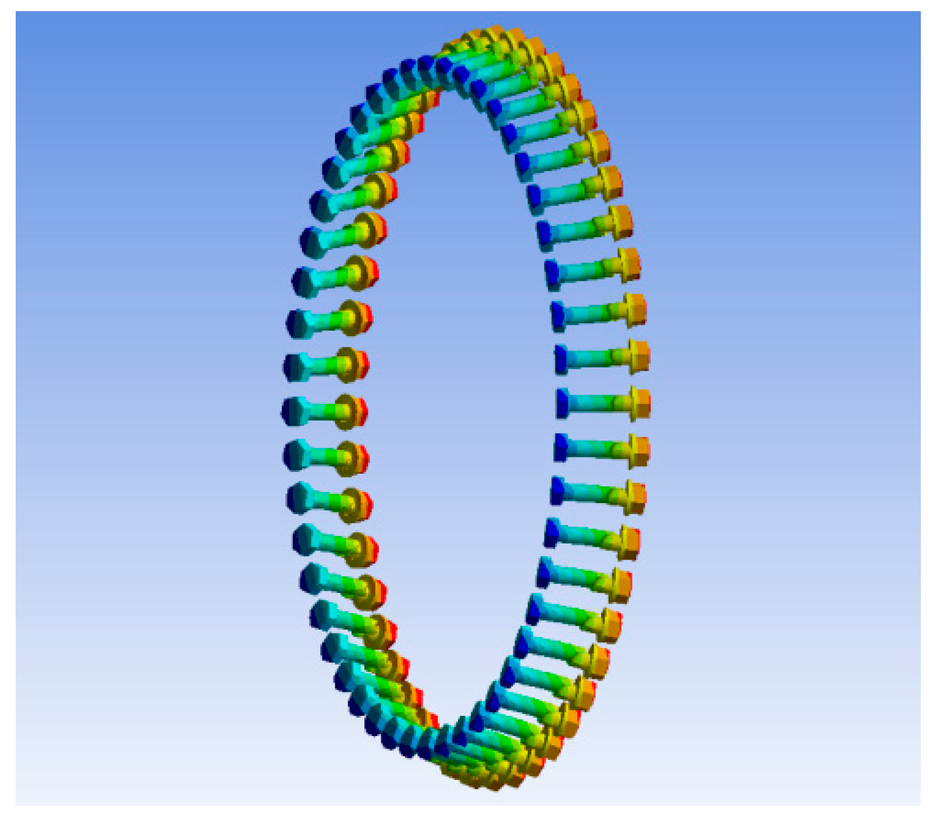
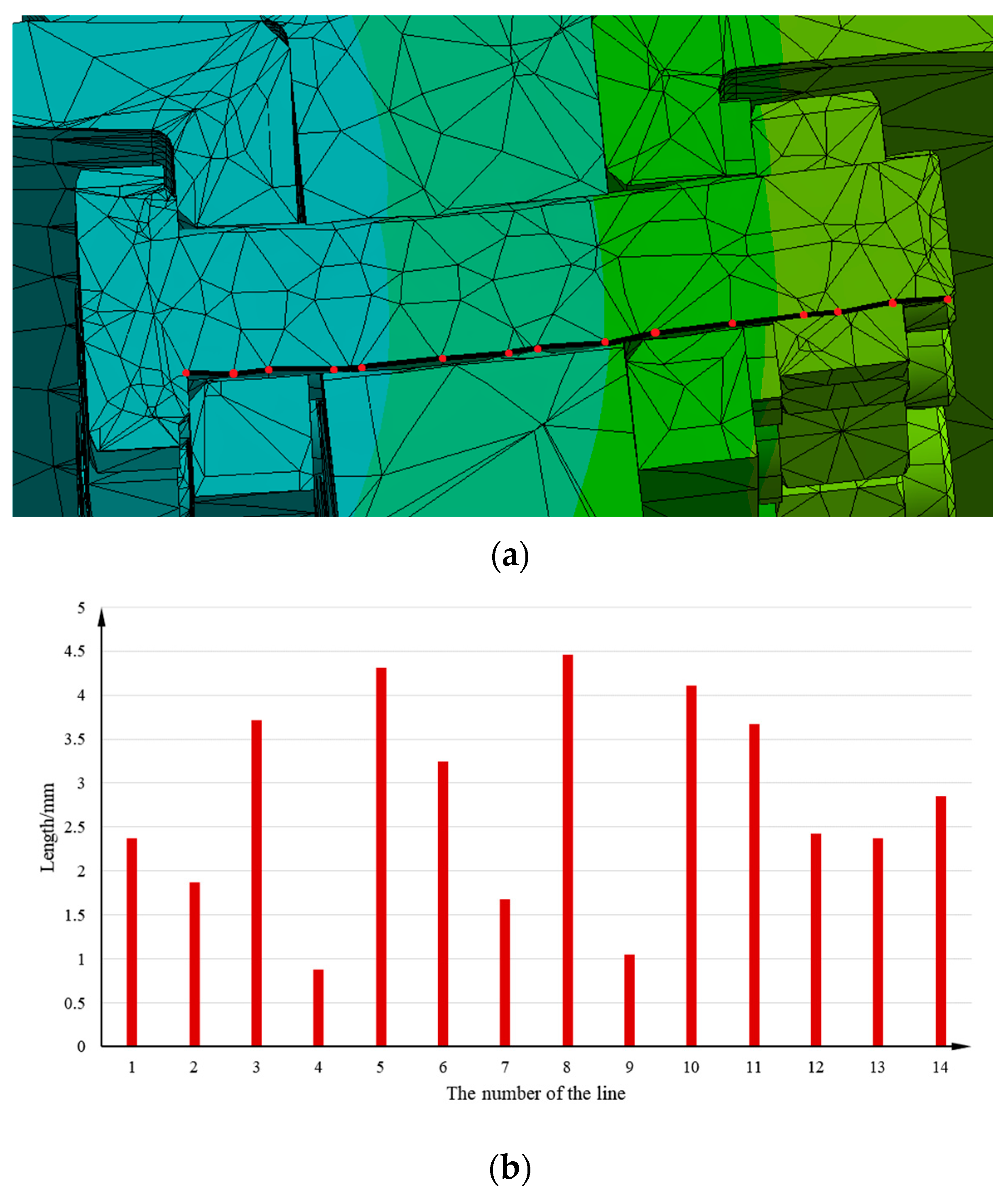
Figure 20. The points in the axial direction of the bolt are considered because it is difficult to measure the distance directly after the bolt deformation due to bending, and the sum of the lengths after connection is equal to the length of the bolt after bending and deformation. The deformation of all bolts is almost the same, as shown in Figure 11; thus, the topmost bolt is representative and is measured. Then, 15 points on the bolt are considered according to the grid division result and numbered 1–15 based on the average, as shown in Figure 21.
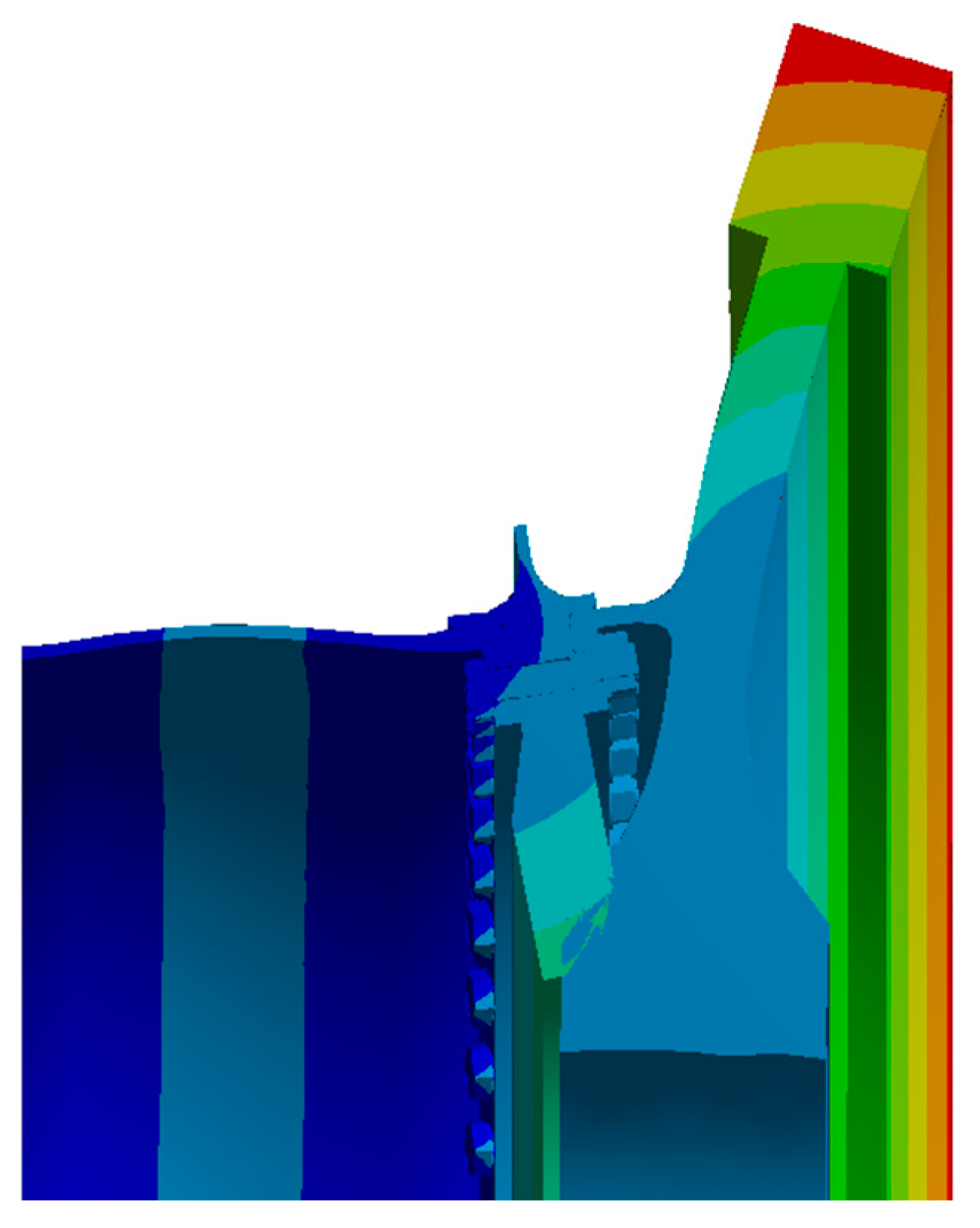
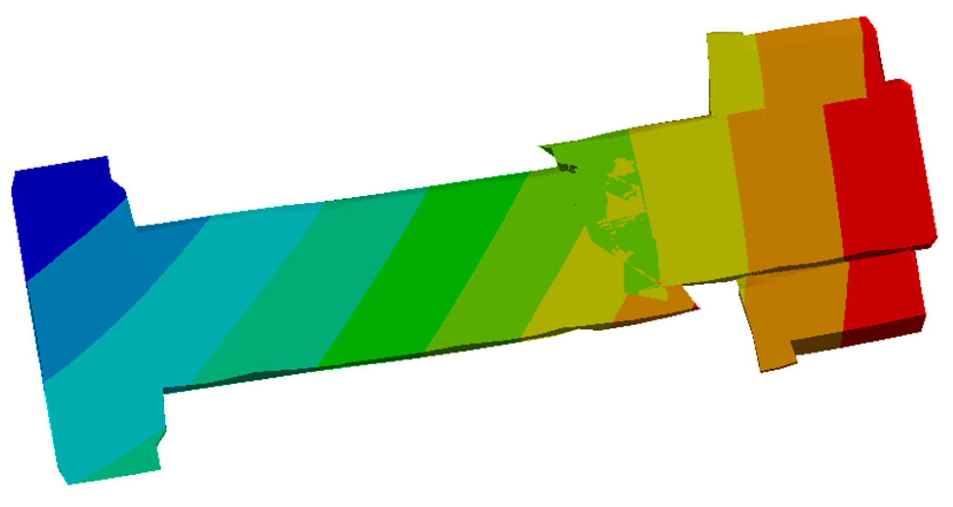
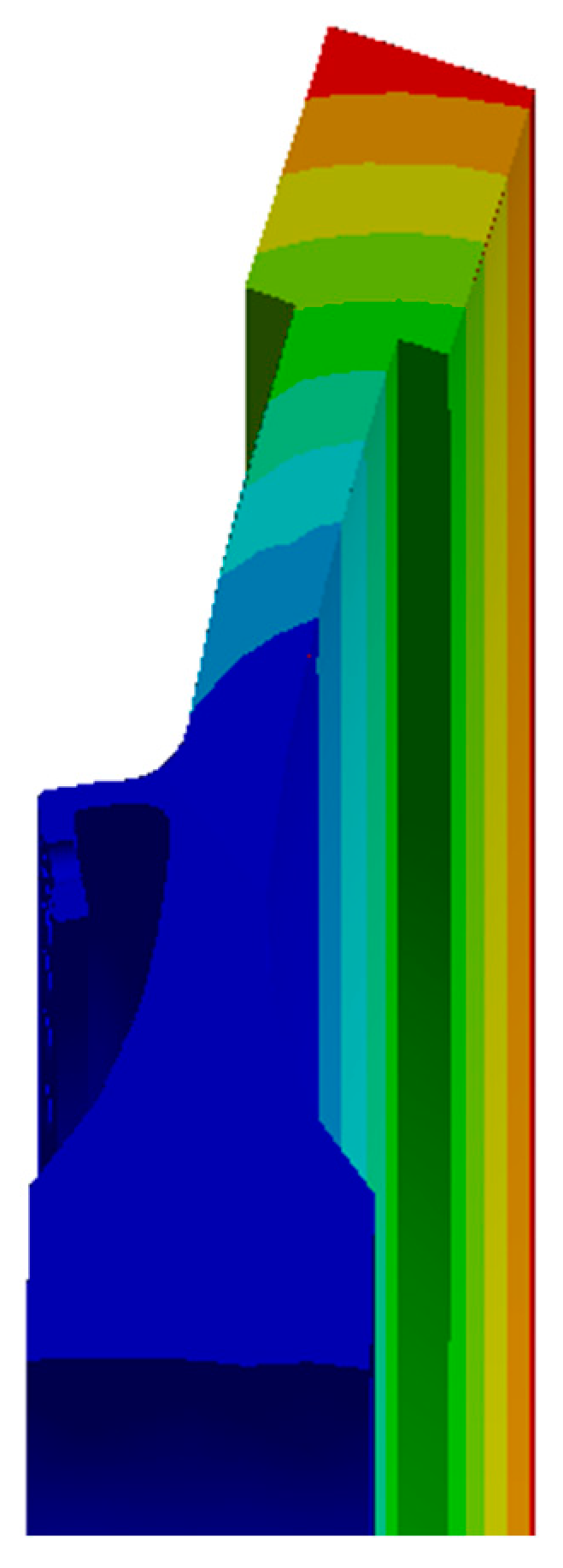
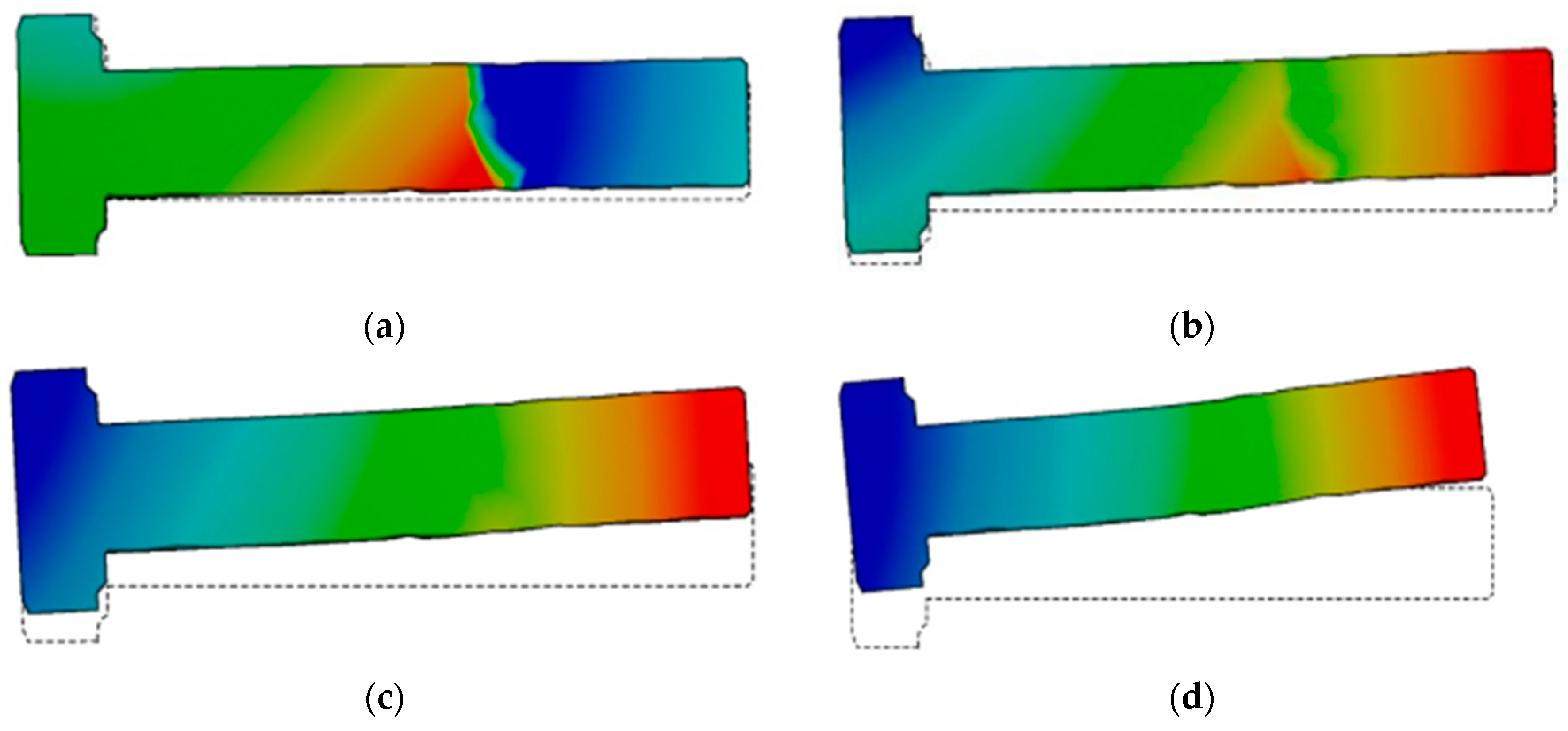
The deformation of the bolt at different rotational speeds under a medium preload and without preloads and rotational speeds is shown in Figure 22, where the deformation cloud is at 10 times the displacement field.
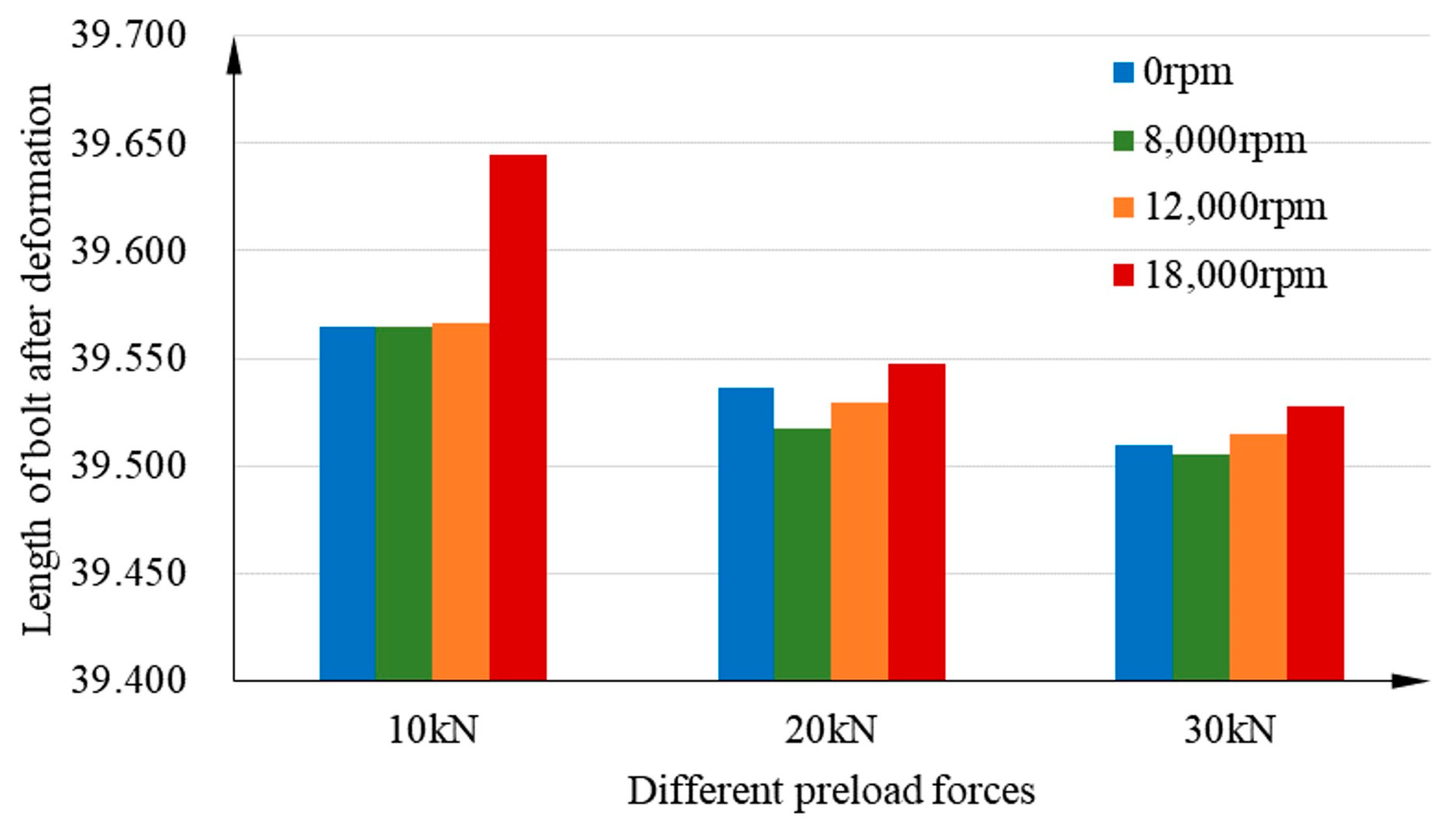
The absolute coordinates of 15 points were extracted to obtain the deformation of the bolt edge in the absolute coordinate system and the length L1 after deformation. The deformed lengths are shown in Table 8, where the bolts are in 12 states.
The phenomenon of excessive deformation in the middle of the bolt at low speeds is mainly caused by excessive preloads, as shown in Figure 22 and Figure 23. However, the bolt deformation is gradually relieved as the rotational speed increases. At different rotational speeds, the bolt is mainly deformed in terms of radial bending, and the change in length deformation in the axial direction is small. As shown in Figure 23, the bolt length is generally shortened under the action of preload force. The deformation is still shorter than the original length, although the axial length of the bolt is longer at higher speeds.
The bolt length increases significantly and exceeds the original length when the preload force is equal to 10 kN and the rotational speed is 18,000 rpm. The deformation of the rabbet shows that the bolt deformation tends to be extremely large and the rabbet is severely separated in the case of low preloads and high speeds. The separation of the rabbet decreases at high speeds and high preloads, so the preload should be sufficient during assembly.

5. Analysis of Uneven Preload Force

5.1. Preload Force Conditions

Section 4.2 suggests that the different preload force has a non-negligible influence on the change in the degree of incoordination. However, the consistency of the preload force cannot be precisely guaranteed during the actual assembly process. In addition, the degree of incoordination has the largest value at a 30 kN preload force and a speed of 18,000 rpm, but the effect on the degree of incoordination is not considered when the preload force is not uniformly distributed. Therefore, the uneven preload force distribution is further investigated.
Two types of value distribution, single rise and double rise, are considered to simulate the uneven preload of each bolt because the uneven distribution of the preload force may result in various situations. The theoretical value of 30 kN is adopted; the error is less than 15%, and the rotational speed is 18,000 rpm in the high-speed range. The distribution of the preload force is shown in Figure 24 and Figure 25. The bolts at special locations were selected for deformation analysis because of the large number of bolts. The deformation of bolts 1, 6, 12, 24, and 36 is considered for the analysis of the two distributions.

5.2. Uncoordinated Deformation of the Rabbet

The results of the rabbet’s deformation in the finite element simulation of the combined structure under the preload distribution types of single rise or double rise are shown in Table 9. The preload force still deforms the bolt at higher working conditions with higher speeds. Although the preload force is sufficient, separation still occurs under the effect of rotational speed. This finding indicates that increasing the preload force at high rotational speeds plays a role in improving the uncoordinated deformation.
The coordinates of the points A, C, E, and F, which are prone to inconsistency, are collected and analyzed in the deformation cloud of the combined structure under different working conditions. Figure 26 and Figure 27 show the degree of incoordination at the corresponding rabbet for each bolt number under the two preload force distributions of single rise and double rise.
With a double-rise preload force distribution, the degree of uncoordinated deformation at the rabbet is slightly higher than that with the single rise. In addition, the consistency of the deformation is improved in the single-rise distribution, although some parts have a higher degree of inconsistency.
Although the preload of the bolts is different in different parts, the greatest degree of inconsistency is still at point C and the degree of inconsistency is above 3. This finding indicates that the deformation error of both parts at this point is more than 0.03 mm. At the same time, point C has the greatest variation under different preloads.

6. Conclusions

In this study, a static analysis of the turbine disc–drum structure is carried out according to finite element software, considering the conditions of preload force, rotational speed, and axial force. The uncoordinated distribution of deformation in the rabbet part of the combined structure is obtained, and the degree of uncoordinated deformation of the rabbet at different preload forces and different rotational speeds is analyzed. Further consideration of the effects produced by the uneven distribution of preload forces under the most uncoordinated operating conditions of deformation leads to the following conclusions:
(1)
The rabbet part of the bolt connection is the main part that undergoes uncoordinated deformation under the condition of a preload force and rotational speed, and the deformation error is up to 0.01 mm. In addition, the deformation of the joint surface of the high-pressure turbine disc and the sealing grate disc is more evident in the highest error of 0.014 mm.
(2)
Although changes in rotational speed have a greater influence on the change in uncoordinated deformation, producing a more serious separation phenomenon with a deformation error of 0.046 mm at high rotational speeds is very easy when the preload is insufficient. Compared with medium speeds, the deformation error increases by 4.4 times at high speeds, and sufficient preloads must be ensured at higher speeds.
(3)
A high preload force at high rotational speed reduces the degree of uncoordinated deformation. However, when the preload force is very high but the speed is insufficient, high stresses of up to 650 MPa may occur in the middle of the bolt, thereby affecting the fatigue life of the bolt. This may also cause extrusion deformation to the component. Therefore, extremely large and extremely small preload forces should be avoided.
(4)
When the preload force distribution is not uniform, the single-rise type has a greater impact on the degree of incongruity. A difference of 0.007 mm in the separation distance between different parts affects the rotor dynamic balance, and it may lead to possible imbalances at high speeds. Therefore, during assembly, it is necessary to ensure the consistency of the preload force size and to avoid large or small preload forces on one side.

Author Contributions

Conceptualization, P.X. and H.W.; methodology, H.W.; software, H.W.; validation, H.W.; formal analysis, H.W.; investigation, H.W.; resources, H.W.; data curation, H.W.; writing—original draft preparation, H.W.; writing—review and editing, P.X. and H.W.; visualization, H.W.; supervision, H.W.; project administration, P.X.; funding acquisition, P.X. All authors have read and agreed to the published version of the manuscript.

Funding

This research is funded by the National Natural Science Foundations of China under grounds U2241274 and 12072288.

Data Availability Statement

No new data were created or analyzed in this study. Data sharing is not applicable to this article.

Conflicts of Interest

The authors declare no conflict of interest.

References

  1. Sun, Y.; Zeng, Z.; Yang, H. The aviation engine box bolt connection structure mechanical characteristics in-fluence factors. J. Mech. Sci. Technol. 2017, 4, 1964–1969. [Google Scholar]
  2. Hallajisani, S.; Kashani, H.; Nobari, A.S. Plate vibration suppression by optimizing friction threshold at its bolted supports. Int. J. Dyn. Control. 2020, 8, 101–111. [Google Scholar] [CrossRef]
  3. Wang, H.Y.; Qin, Z.Y.; Chu, F.L. Effect of Bolt Number on Joint Stiffness of Disc and Drum Connected by Bolted Joints. In Proceedings of the International Conference on Electrical, Phuket, Thailand, 20–21 December 2015. [Google Scholar]
  4. Panja, D.; Barkema, G.T.; Ball, R.C. Effect of Anomalous Dynamics on Unbiased Polymer Translocation. arXiv 2007, arXiv:cond-mat/0610671. [Google Scholar]
  5. Qin, Z.Y.; Wang, H.Y.; Chu, F.L. Finite Element Modeling and Dynamic Analysis of Rotating Disc and Drum Connected by Bolted Joints. In Proceedings of the Advanced Engineering Forum, Ostrava, Czech Republic, 9–10 October 2012. [Google Scholar]
  6. Qin, Z.Y.; Han, Q.K.; Chu, F.L. Analytical model of bolted disk-drum joints and its application to dynamic analysis of jointed rotor. ARCHIVE Proc. Inst. Mech. Eng. Part C J. Mech. Eng. Sci. 2014, 228, 646–663. [Google Scholar] [CrossRef]
  7. Zou, C.; Xia, H.; Chen, K.; Zhai, J.; Han, Q. Research on the identification method of the pre-tightening state of the matching surface of the aero-engine disk-drum rotor. Eng. Fail. Anal. 2022, 136, 106–118. [Google Scholar] [CrossRef]
  8. Kopei, V.; Onysko, O.; Barz, C.; Dašić, P.; Panchuk, V. Designing a Multi-Agent PLM System for Threaded Connections Using the Principle of Isomorphism of Regularities of Complex Systems. Machines 2023, 11, 263. [Google Scholar] [CrossRef]
  9. Tang, Q.; Li, C.; She, H.; Wen, B. Nonlinear response analysis of bolted joined cylindrical-cylindrical shell with general boundary condition. J. Sound Vib. 2019, 443, 788–803. [Google Scholar] [CrossRef]
  10. Yao, X.; Wang, J.; Zhai, X. Research and application of improved thin-layer element method of aero-engine bolted joints. Proc. Inst. Mech. Eng. Part G J. Aerosp. Eng. 2017, 231, 823–839. [Google Scholar] [CrossRef]
  11. Liu, S.; Ma, Y.; Zhang, D.; Hong, J. Studies on dynamic characteristics of the joint in the aero-engine rotor system. Mech. Syst. Signal Process. 2012, 29, 120–136. [Google Scholar]
  12. Tol, S.; Ozguven, H.N. Dynamic characterization of bolted joints using FRF decoupling and optimization. Mech. Syst. Signal Process. 2015, 54–55, 124–138. [Google Scholar] [CrossRef]
  13. Gaul, L.; Lenz, J. Nonlinear dynamics of structures assembled by bolted joints. Acta Mech. 1997, 125, 169–181. [Google Scholar] [CrossRef]
  14. Bograd, S.; Reuss, P.; Schmidt, A.; Gaul, L.; Mayer, M. Modeling the dynamics of mechanical joints. Mech. Syst. Signal Process. 2011, 25, 2801–2826. [Google Scholar] [CrossRef]
  15. Boeswald, M.; Link, M.; Meyer, S. Experimental and analytical investigations of non-linear cylindrical casing joints using base excitation testing. In Proceedings of the International Modal Analysis Conference, Orlando, FL, USA, 5–8 February 2003; pp. 3–6. [Google Scholar]
  16. Hong, J.; Yu, P.; Ma, Y.; Zhang, D. Investigation on nonlinear lateral-torsional coupled vibration of a rotor system with substantial unbalance. Chin. J. Aeronaut. 2020, 33, 1642–1660. [Google Scholar] [CrossRef]
  17. Venczel, M.; Veress, Á.; Szentmiklósi, L.; Kis, Z. Dynamic Thermal Neutron Radiography for Filling Process Analysis and CFD Model Validation of Visco-Dampers. Machines 2023, 11, 485. [Google Scholar] [CrossRef]
  18. Ouyang, H.; Oldfield, M.J.; Mottershead, J.E. Experimental and theoretical studies of a bolted joint excited by a torsional dynamic load. Int. J. Mech. Sci. 2006, 48, 1447–1455. [Google Scholar] [CrossRef]
  19. Campos, U.A.; Hall, D.E. Simplified Lamé’s equations to determine contact pressure and hoop stress in thin-walled press-fits. Thin Walled Struct. 2019, 138, 199–207. [Google Scholar] [CrossRef]
  20. Liu, Y.; Wang, J.; Chen, L. Dynamic characteristics of the flange joint with a snap in aero-engine. Int. J. Acoust. Vib. 2018, 23, 168–174. [Google Scholar] [CrossRef]
  21. Wang, Z.; Li, J.; Liu, Y. Stiffness characteristics of flange joint with a snap and its influence on structure vibration. J. Aerosp. Power 2019, 34, 1201–1208. [Google Scholar]
  22. Ibrahim, R.A.; Pettit, C.L. Uncertainties and dynamic problems of bolted joints and other fasteners. J. Sound Vib. 2005, 279, 857–936. [Google Scholar] [CrossRef]
Figure 1. The combined turbine disc–drum structure.
Machines 11 00661 g001
Figure 2. Bolted connection.
Machines 11 00661 g002
Figure 3. Force diagram of the combined disc.
Machines 11 00661 g003
Figure 4. The FEM of the disc–drum combined structure.
Machines 11 00661 g004
Figure 5. Deformation results for different mesh sizes.
Machines 11 00661 g005
Figure 6. Overall deformation.
Machines 11 00661 g006
Figure 7. Uncoordinated deformation points.
Machines 11 00661 g007
Figure 8. Before deformation.
Machines 11 00661 g008
Figure 9. After deformation.
Machines 11 00661 g009
Figure 10. Cross-sectional view of bolt deformation.
Machines 11 00661 g010
Figure 11. Positions of 48 sets of bolts.
Machines 11 00661 g011
Figure 12. The drum shaft.
Machines 11 00661 g012
Figure 13. The sealing grate tooth plate.
Machines 11 00661 g013
Figure 14. The high-pressure turbine disc.
Machines 11 00661 g014
Figure 15. Comparison of the degree of incongruity.
Machines 11 00661 g015
Figure 16. Uncoordinated deformation 1.
Machines 11 00661 g016
Figure 17. Uncoordinated deformation 2.
Machines 11 00661 g017
Figure 18. Comparison of the degree of incongruity in different states.
Machines 11 00661 g018
Figure 19. Incoordination of key points in different states. (a) Status 4, (b) Status 5, (c) Status 6.
Machines 11 00661 g019aMachines 11 00661 g019b
Figure 20. Undeformed bolt length.
Machines 11 00661 g020
Figure 21. The points and lines on the bolt. (a) The separation points and lines, (b) The length of lines.
Machines 11 00661 g021
Figure 22. Deformation of bolts at different speeds with a medium preload force. (a) F = 20 kN v = 0 rpm, (b) F = 20 kN v = 8000 rpm, (c) F = 20 kN v = 12,000 rpm, (d) F = 20 kN v = 18,000 rpm.
Machines 11 00661 g022
Figure 23. Length of the bolt in different states.
Machines 11 00661 g023
Figure 24. Distribution of the preload force for single rise.
Machines 11 00661 g024
Figure 25. Distribution of the preload force for double rise.
Machines 11 00661 g025
Figure 26. Distribution of the preload force for single-rise distribution.
Machines 11 00661 g026
Figure 27. Distribution of the preload force for double-rise distribution.
Machines 11 00661 g027
Table 1. Material parameters.
MaterialsDensity kg/m3Young’s Modulus MPaPoisson’s Ratio
GH416982401.99 × 1050.33
Structural steel78502.00 × 1050.30
Table 2. Result of grid independence verification.
Grid Size/mmNumber of NodesNumber of ElementsMaximum Deformation/mm
40132,52269,0570.854
30132,51768,5910.869
20167,38589,6640.882
10312,023181,5480.894
8430,366259,1490.898
Table 3. Combination of two components.
CombinationTwo Components
No. 1Sealing grate discDrum shaft
No. 2Sealing grate discHigh-pressure turbine disc
No. 3BoltDrum shaft
No. 4BoltSealing grate disc
No. 5BoltHigh-pressure turbine disc
Table 4. Degree of incongruity between different components.
CombinationABCDEF
No. 10.54810.5179
No. 2 1.43911.11011.06870.5294
No. 30.89960.6769
No. 40.91581.05752.22422.3257
No. 5 1.97311.2163
Table 5. Rotational speeds and preload forces.
8000 rpm12,000 rpm18,000 rpm
10 kNStatus 1Status 2Status 3
20 kNStatus 4Status 5Status 6
30 kNStatus 7Status 8Status 9
Table 6. Deformation of bolt joints under different working conditions.
Machines 11 00661 i001Machines 11 00661 i002Machines 11 00661 i003
Status 1Status 2Status 3
Machines 11 00661 i004Machines 11 00661 i005Machines 11 00661 i006
Status 4Status 5Status 6
Machines 11 00661 i007Machines 11 00661 i008Machines 11 00661 i009
Status 7Status 8Status 9
Table 7. The degree of incongruity in different states.
StatusPreload Force/kNRotational Speed/rpmPoint APoint CPoint EPoint F
Status 11080000.54811.43911.06870.5294
Status 21012,0000.84661.96241.34970.3560
Status 31018,0004.57173.09511.70960.9503
Status 42080000.70541.63440.99910.2017
Status 52012,0001.00932.25321.49360.3381
Status 62018,0001.67153.48032.63551.1034
Status 73080000.87181.91161.18160.2786
Status 83012,0001.11422.61691.79250.3243
Status 93018,0001.98583.62712.89361.0866
Table 8. Length of the bolt after deformation and the degree of deformation.
No.Preload Force/kNRotational Speed/rpmLength of the Bolt after Deformation L1/mmElongation of the BoltL1–L0/mm(L1–L0)/L0
10039.60000
210039.564−0.036−0.09%
310800039.565−0.035−0.09%
41012,00039.566−0.034−0.09%
51018,00039.6450.0450.11%
620039.537−0.063−0.16%
720800039.517−0.083−0.21%
82012,00039.529−0.071−0.18%
92018,00039.548−0.052−0.13%
1030039.510−0.090−0.23%
1130800039.505−0.095−0.24%
123012,00039.515−0.085−0.21%
133018,00039.527−0.073−0.18%
Table 9. Deformation of the rabbet under different types of preload distribution.
Number of BoltSingle RiseDouble Rise
1Machines 11 00661 i010Machines 11 00661 i011
6Machines 11 00661 i012Machines 11 00661 i013
12Machines 11 00661 i014Machines 11 00661 i015
24Machines 11 00661 i016Machines 11 00661 i017
36Machines 11 00661 i018Machines 11 00661 i019
Disclaimer/Publisher’s Note: The statements, opinions and data contained in all publications are solely those of the individual author(s) and contributor(s) and not of MDPI and/or the editor(s). MDPI and/or the editor(s) disclaim responsibility for any injury to people or property resulting from any ideas, methods, instructions or products referred to in the content.

