
Experimental Research on the Formation of the Third Body on the Friction Surface of Coal Cake Tamper Hammer Lifting Mechanism

Abstract
:1. Introduction
- An equivalent accumulation method is proposed to use the wear states of several samples under different wear times to equivalently characterize the wear conditions of a sample in different stages of continuous wear, and the different stages of the third-body formation process are obtained.
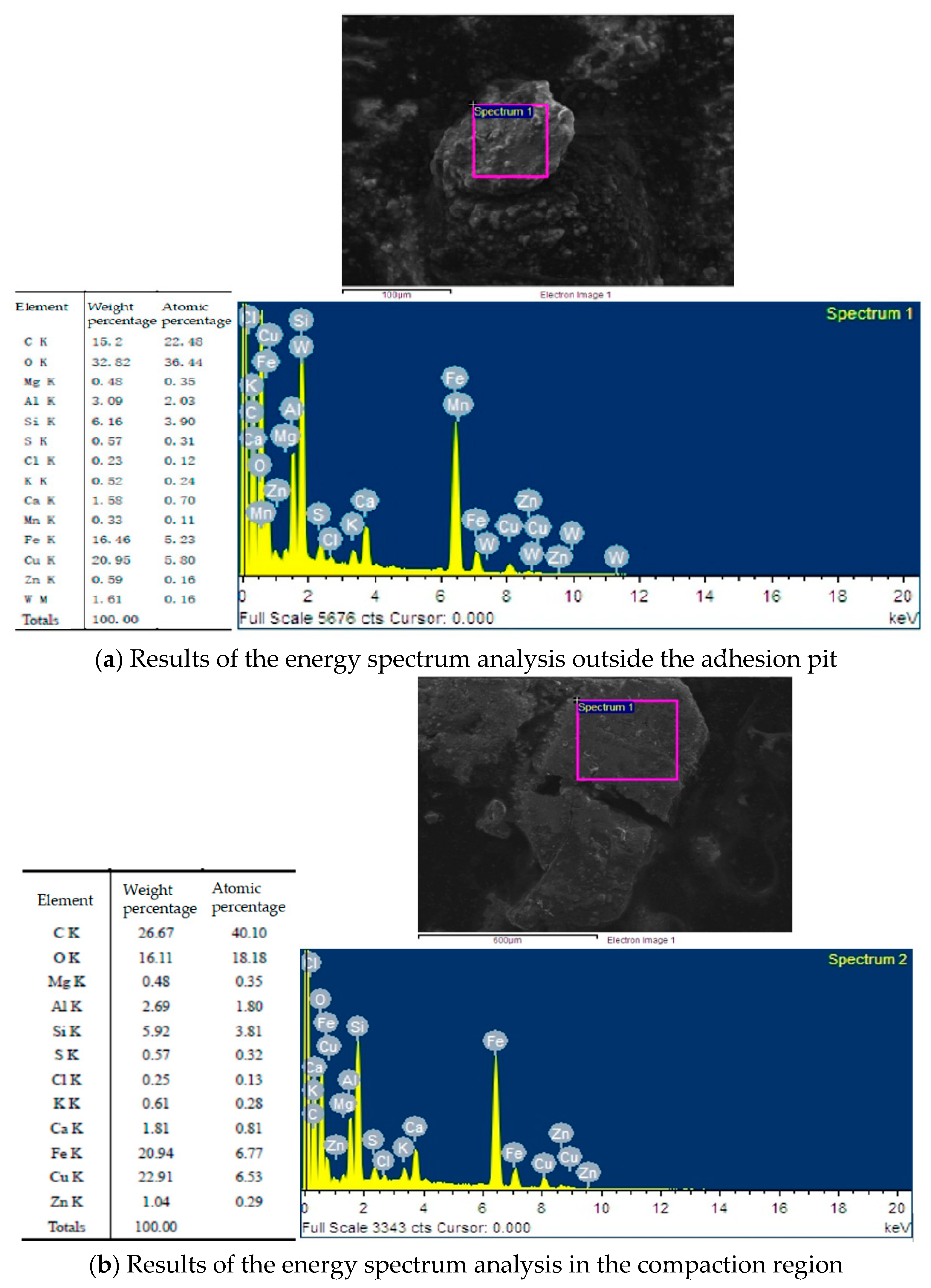
- By analyzing the microscopic changes in the composition of the third body at different wear times and the content proportion of each element on the surface of the disc, it is determined that Cu is the key indicator of the emergence of the third body. The content of the Cu element is used to characterize the content of the third body on the surface of the disk sample, and the formation rule of the third body on the surface of the disk is inferred.
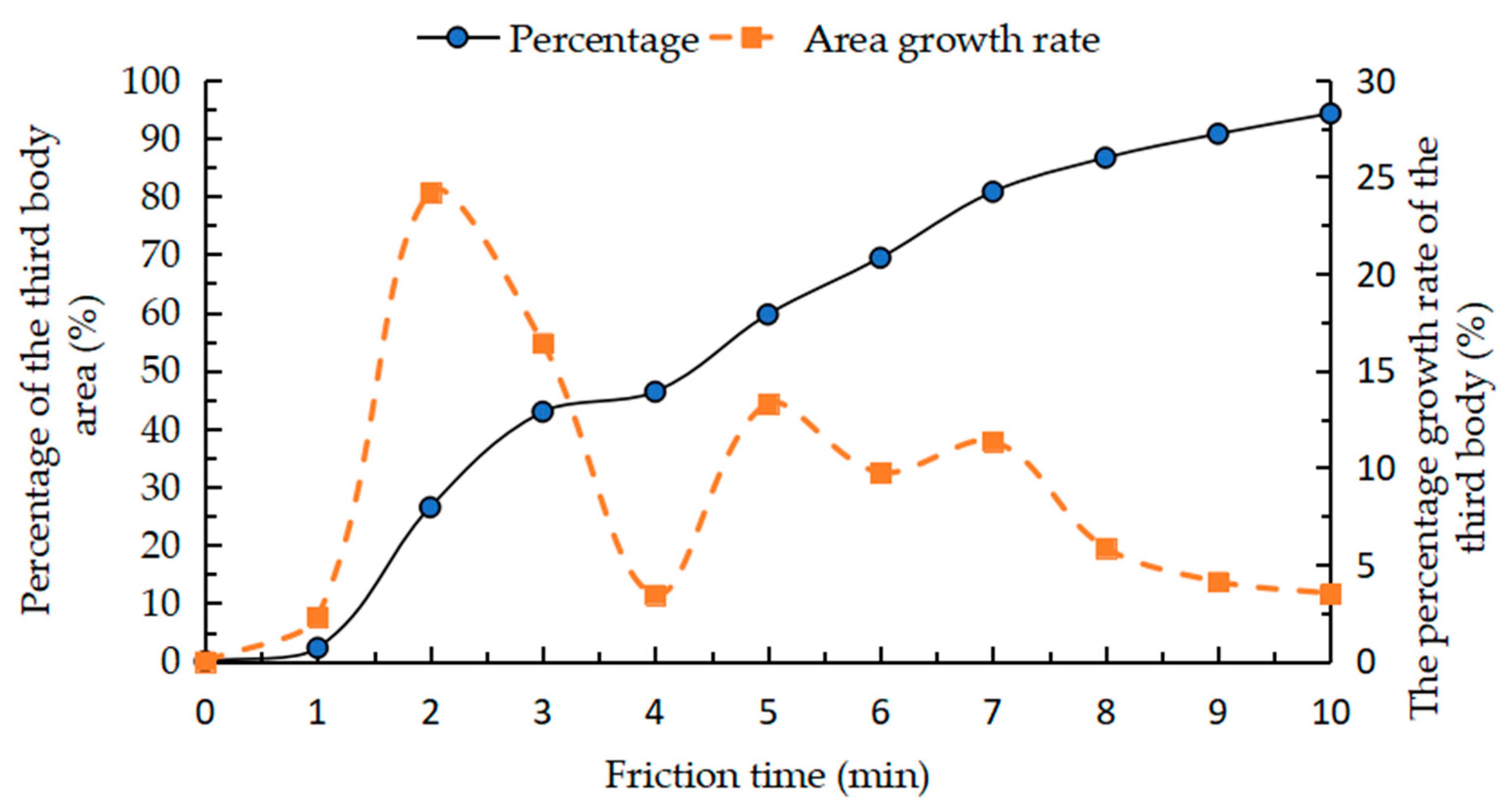
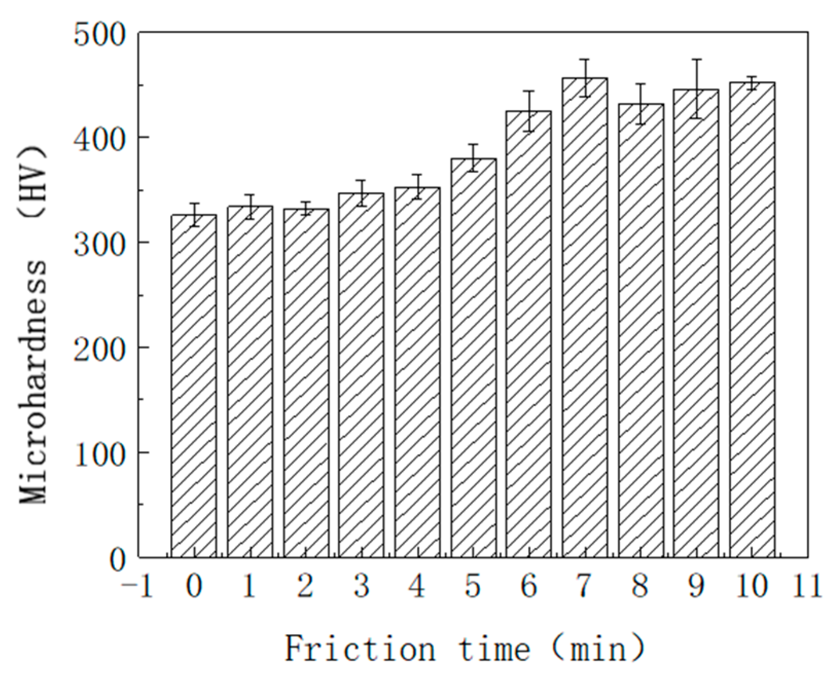
- Through an image processing method of color analysis, the distribution law of the third body on the whole disk is identified. The friction performance of the disk surface is obtained by analyzing the changes of hardness and morphology at each friction stage.
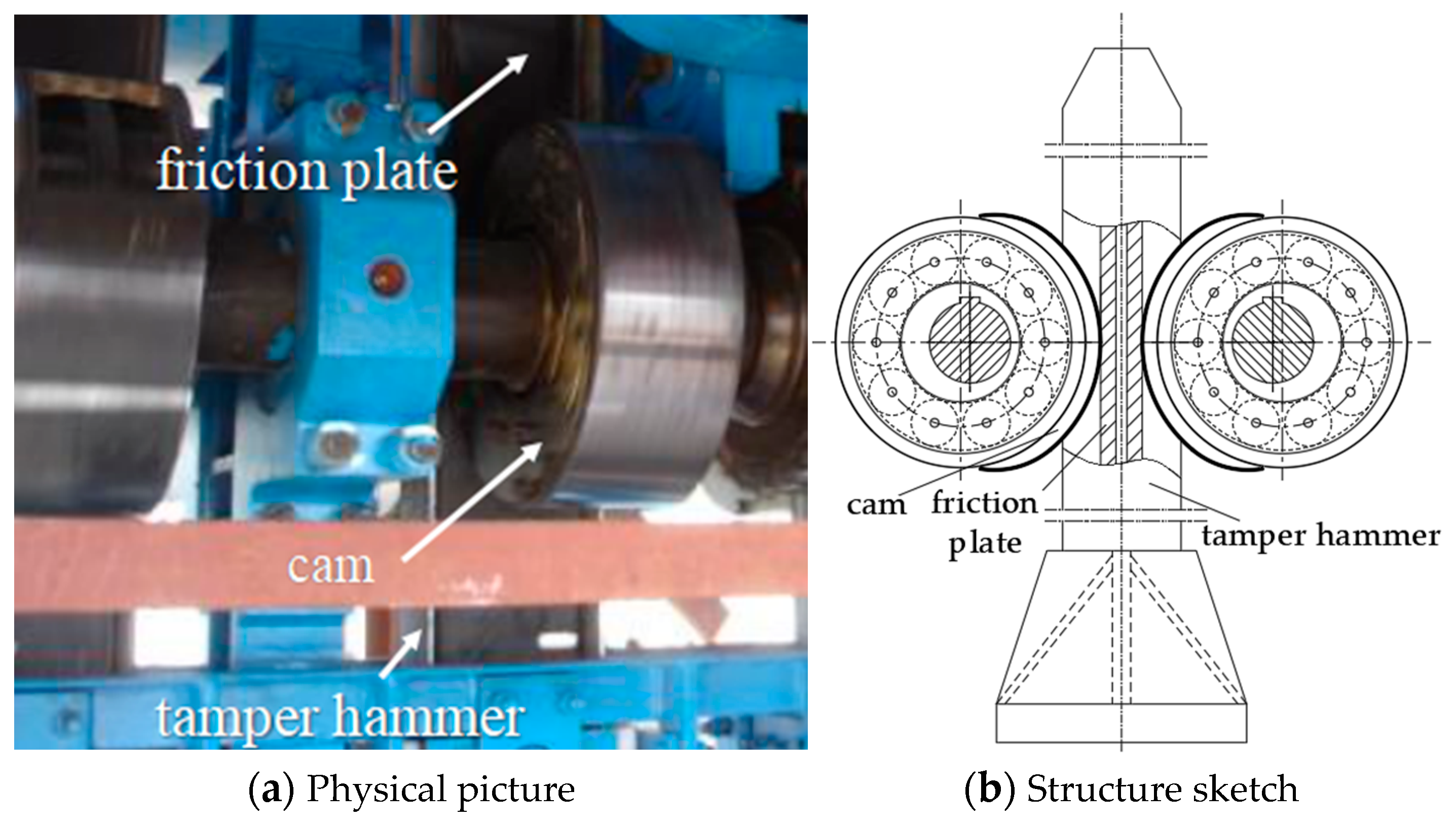
2. Experimental Design of the Third-Body Formation Process
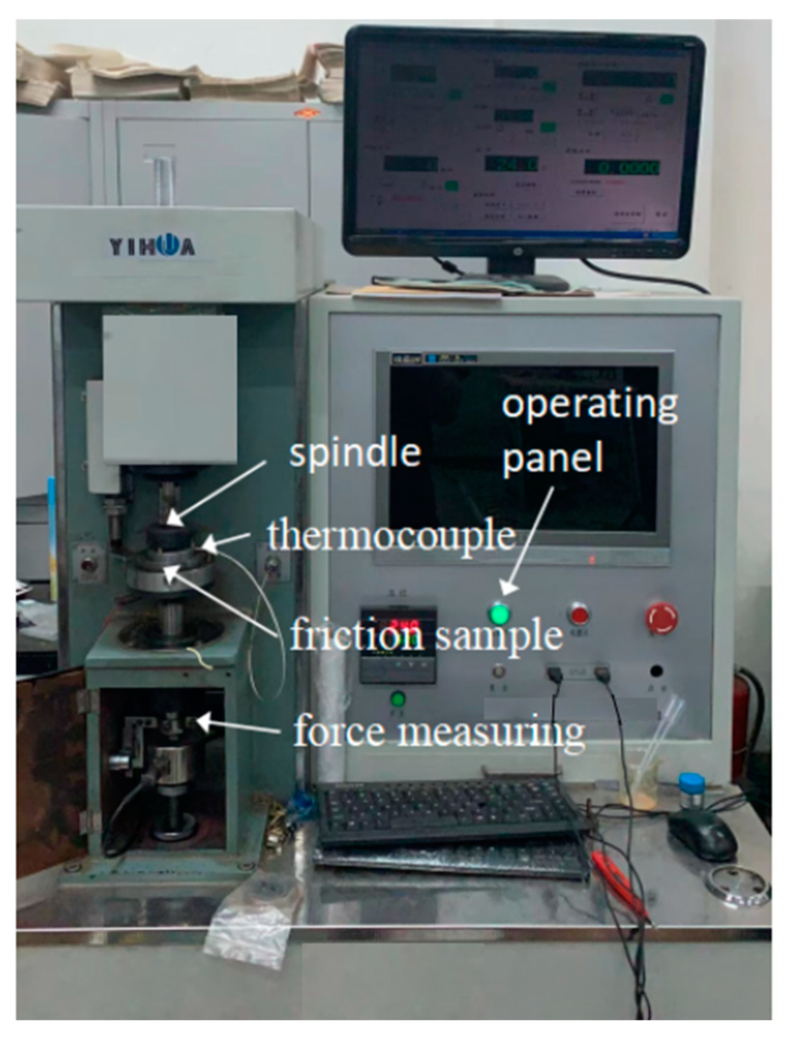
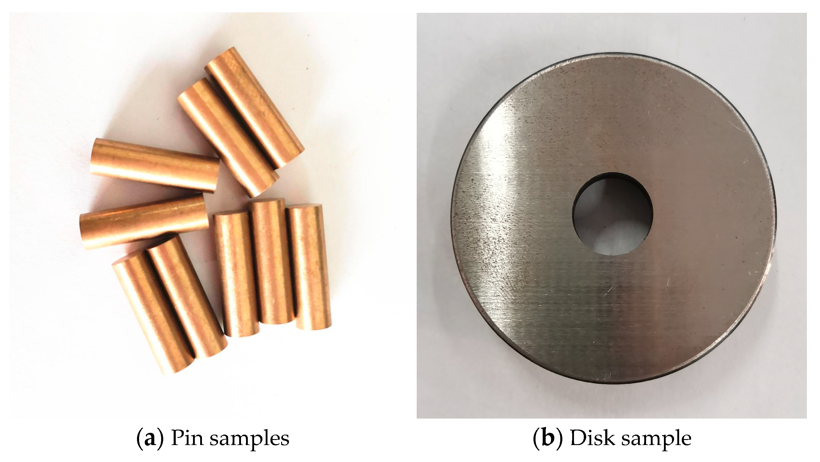
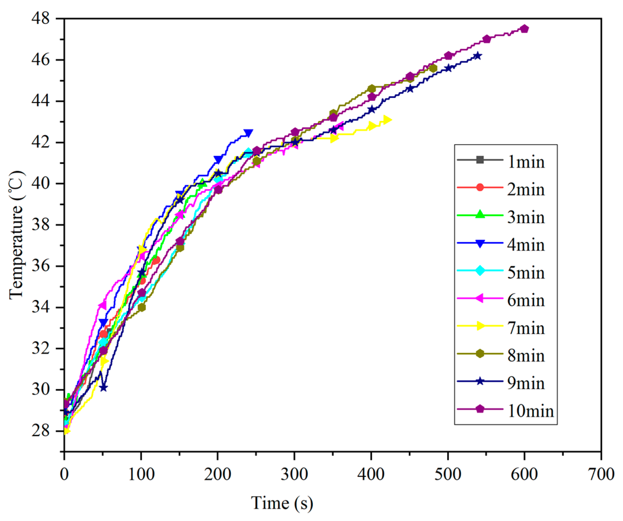
2.1. Test Method
2.2. Test Plan
3. Third-Body Analysis with Different Friction Times
3.1. Third-Body Surface Composition Analysis
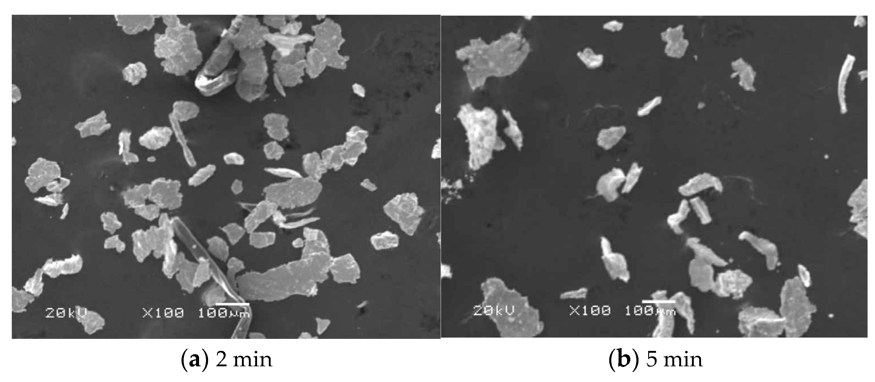
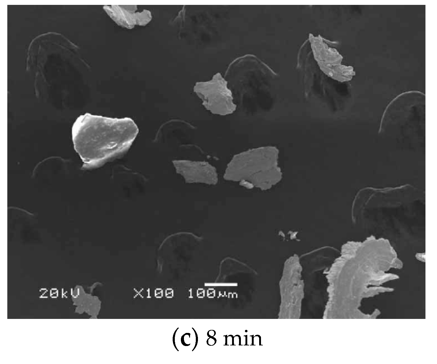
3.2. The Third-Body Particle Analysis
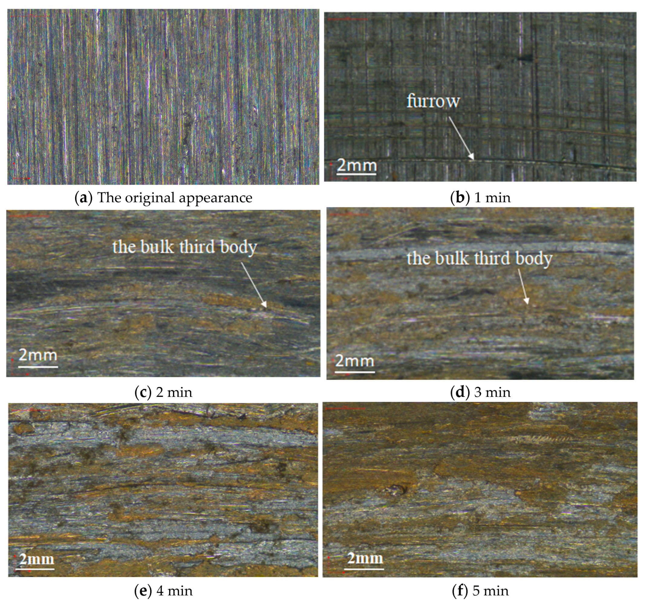
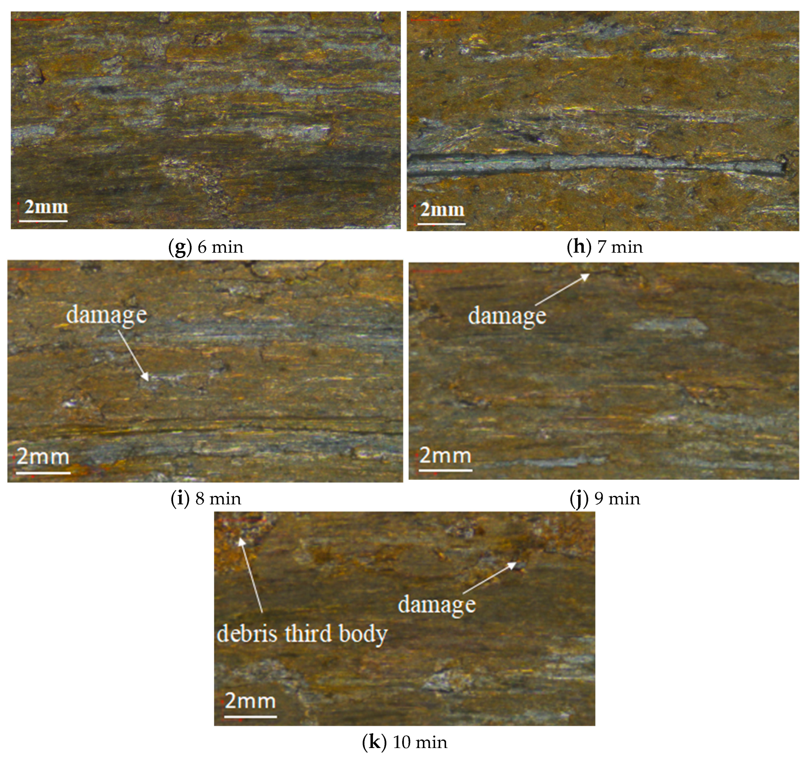
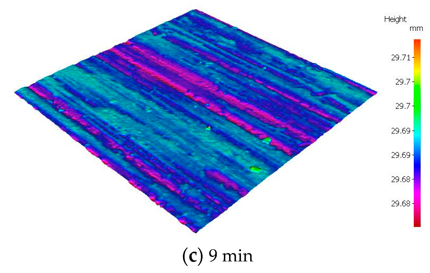
3.3. Analysis of Surface Morphology during the Formation of the Third Body
4. Performance Test of the Friction Surface at Different Friction Times
4.1. Microhardness Analysis
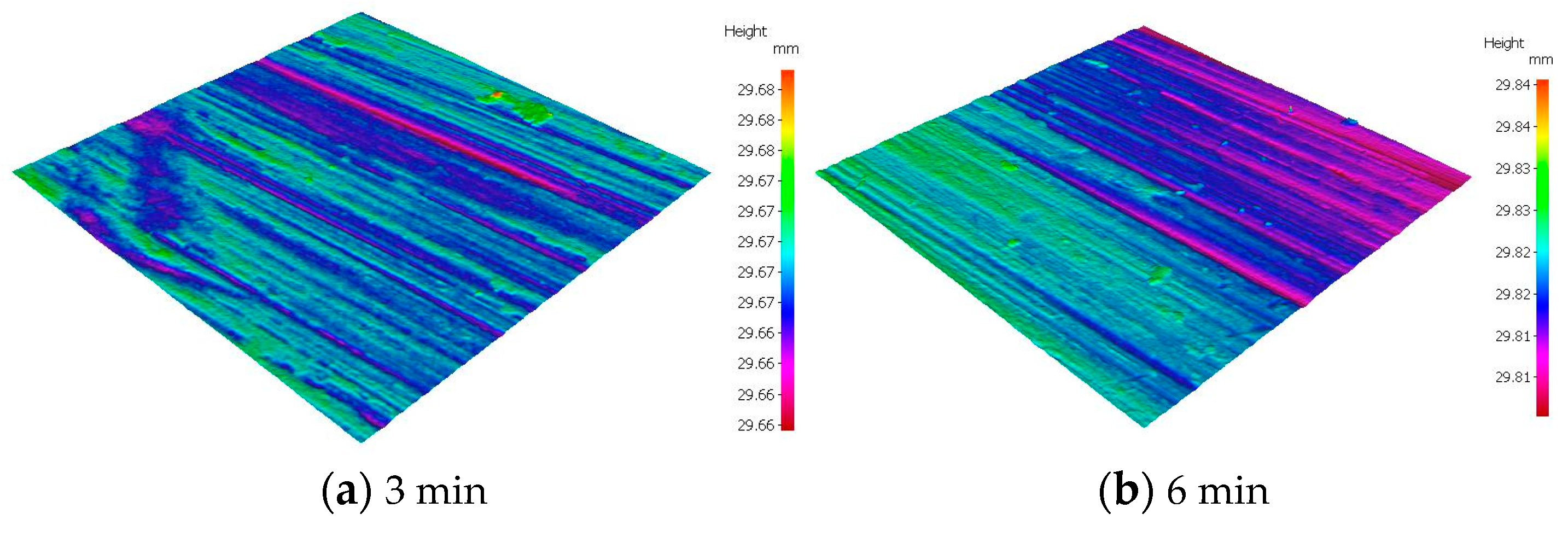
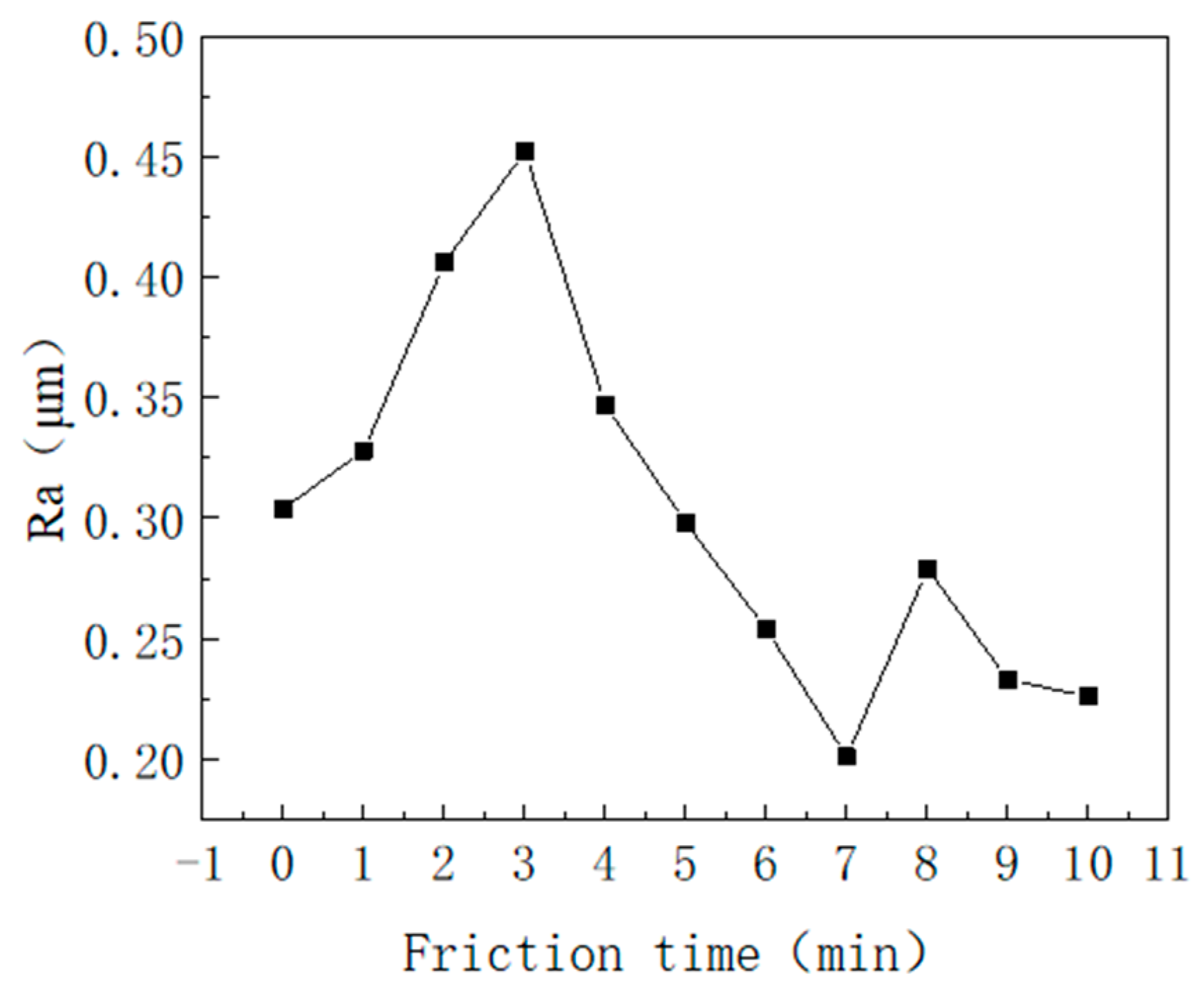
4.2. Surface Roughness Analysis
5. Conclusions
6. Prospect of Research Work
Author Contributions
Funding
Data Availability Statement
Conflicts of Interest
References
- Li, X.; Li, Z.; Jin, S.; Zhang, J.; Niu, Z.; Liu, J. Contact Properties Research for Linear Sliding Guide Rail with the Fractal Theory. In Proceedings of the ASME 2019 International Mechanical Engineering Congress and Exposition, Calvin L. Rampton Salt Palace Convention Center, Salt Lake City, UT, USA, 11 November 2019. [Google Scholar]
- Lu, J.; Pan, B.; Che, T.; Sha, D. Discrete Element Analysis of Friction Performance for Tire-Road Interaction. Ind. Lubr. Tribol. 2020, 72, 977–983. [Google Scholar] [CrossRef]
- Wang, Y.; Gang, L.; Liu, S.; Cui, Y. Coupling Fractal Model for Fretting Wear on Rough Contact Surfaces. J. Tribol. 2020, 143, 091701. [Google Scholar] [CrossRef]
- Hao, Q.; Yin, J.; Liu, Y.; Jin, L.; Zhang, S.; Sha, Z. Time-varying Wear Calculation Method for Fractal Rough Surfaces of Friction Pairs. Coatings 2023, 13, 270. [Google Scholar] [CrossRef]
- Zuo, X.; Zhou, Y.; Ma, C.; Fang, H. Dynamic Identification of Wear State Based on Nonlinear Parameters. Fractals 2019, 27, 1885–1891. [Google Scholar] [CrossRef]
- Xu, C.; Wu, T.; Huo, Y.; Yang, H. In-situ Characterization of Three Dimensional Worn Surface under Sliding-Rolling Contact. Wear 2019, 426–427, 1781–1787. [Google Scholar] [CrossRef]
- Godet, M. The Third-body Approach a Mechanical View of Wear. Wear 1984, 100, 437–452. [Google Scholar] [CrossRef]
- Berthier, Y.; Colombie, C.; Vincent, L.; Godet, M. Fretting Wear Mechanisms and Their Effects on Fretting Fatigue. J. Tribol. -Trans. Asme 1988, 110, 517–524. [Google Scholar] [CrossRef]
- Eriksson, M.; Bergman, F.; Jacobson, S. On the Nature of Tribological Contact in Automotive Brakes. Wear 2002, 252, 26–36. [Google Scholar] [CrossRef]
- Xu, G.-Z.; Liu, J.-J.; Zhou, Z.-R.; Zhon, Z.-R. The Effect of the Third Body on the Fretting Wear Behavior of Coatings. J. Mater. Eng. Perform. 2002, 11, 288–293. [Google Scholar] [CrossRef]
- Cao, M. Effect of Braking Condition on the Friction and Wear Properties of Brake Pad; Dalian Jiaotong University: Dalian, China, 2008. (In Chinese) [Google Scholar]
- Dolgopolov, K.N.; Lyubimov, D.N.; Ponomarenko, A.G.; Chigarenko, G.G.; Boiko, M.V. The Structure of Lubricating Layers Appearing during Friction in the Presence of Additives of Mineral Friction Modifiers. J. Frict. Wear 2009, 30, 377–380. [Google Scholar] [CrossRef]
- Yang, Y. Study on the Third Body on the Surface of Brake Disc Material; Beijing Jiaotong University: Beijing, China, 2012. (In Chinese) [Google Scholar]
- Bulnes, R. Mechanochemical Friction of Third-body as an Exergetic Collision. Tribol. Online 2011, 6, 55–63. [Google Scholar] [CrossRef]
- Perumean, D.W. The Force Between Two Sliding Bodies When Observed from a Third Moving Body. Tribol. Online 2011, 6, 185–188. [Google Scholar] [CrossRef] [Green Version]
- Lei, B.; Yi, M.; Xu, H.; Ran, L.; Ge, Y.; Peng, K. Microstructures of the Worn Surface Layer of C/C Composites. Acta Mater. Compos. Sin. 2010, 27, 64–69. [Google Scholar]
- Diomidis, N.; Mischler, S. Third Body Effects on Friction and Wear during Fretting of Steel Contacts. Tribol. Int. 2011, 44, 1452–1460. [Google Scholar] [CrossRef]
- Stoyanov, P.; Romero, P.A.; Järvi, T.T.; Pastewka, L.; Scherge, M.; Stemmer, P.; Fischer, A.; Dienwiebel, M.; Moseler, M. Experimental and Numerical Atomistic Investigation of the Third Body Formation Process in Dry Tungsten/Tungsten-Carbide Tribo Couples. Tribol. Lett. 2013, 50, 67–80. [Google Scholar] [CrossRef]
- Lepesant, P.; Boher, C.; Berthier, Y.; Rézai-Aria, F. A Phenomenological Model of the Third Body Particles Circulation in a High Temperature Contact. Wear 2013, 298–299, 66–79. [Google Scholar] [CrossRef] [Green Version]
- Su, L.; Gao, F.; Han, X.; Chen, J. Effect of Copper Powder Third Body on Tribological Property of Copper-based Friction Materials. Tribol. Int. 2015, 90, 420–425. [Google Scholar] [CrossRef]
- Gao, F.; Miao, J.; Han, X.; Fu, R.; Chen, J. Relationship between Arrangement Patterns and Tribological Properties of Copper-aluminum-graphite Materials. Ind. Lubr. Tribol. 2016, 68, 170–175. [Google Scholar] [CrossRef]
- Zhu, T.; Shipway, P.; Sun, W. The Dependence of Wear Rate on Wear Scar Size in Fretting; The Role of Debris Expulsion from the Contact. Wear 2019, 440–441, 203081. [Google Scholar] [CrossRef]
- Liskiewicz, T.; Kubiak, K.; Mann, D.; Mathia, T. Analysis of Surface Roughness Morphology with TRIZ Methodology in Automotive Electrical Contacts, Design against Third Body Fretting-corrosion. Tribol. Int. 2020, 143, 106019. [Google Scholar] [CrossRef]
- Zhang, P.; Zhang, L.; Wei, D.; Wu, P.; Cao, J.; Shijia, C.; Qu, X. Substance Evolution and Wear Mechanism on Friction Contact Area of Brake Disc for High-speed Railway Trains at High Temperature. Eng. Fail. Anal. 2020, 111, 104472. [Google Scholar] [CrossRef]
- Jayanta, M.; Karabi, D.; Siddhartha, D. An Investigation of Mechanical Property and Sliding Wear Behavior of 400HV Grade Martensitic Steels. Wear Int. J. Sci. Technol. Frict. Lubr. Wear 2020, 458–459, 203081. [Google Scholar]
- Hu, J.; Yuan, F.; Liu, X.; Wei, Y. Effect of Plasticity on Nanoscale Wear of Third-body Particles. Tribol. Int. 2021, 155, 106739. [Google Scholar] [CrossRef]
- Ahmadi, A.; Sadeghi, F. A Novel Three-Dimensional Finite Element Model to Simulate Third Body Effects on Fretting Wear of Hertzian Point Contact in Partial Slip. J. Tribol. 2021, 143, 4048386. [Google Scholar] [CrossRef]
- Shpenev, A.G.; Muravyeva, T.I.; Shkalei, I.V.; Bukovskiy, P.O. Influence of the Surface Film (Third Body) on the Friction and Wear Process of Carbon-Fiber Composites. J. Surf. Investig. 2022, 16, 397–401. [Google Scholar] [CrossRef]
- Li, Y.; Schreiber, P.; Schneider, J.; Greiner, C. Tribological Mechanisms of Slurry Abrasive Wear. Friction 2023, 11, 1079–1093. [Google Scholar] [CrossRef]
- Brink, T.; Milanese, E.; Molinari, J.F. Effect of Wear Particles and Roughness on Nanoscale Friction. Phys. Rev. Mater. 2022, 6, 136–142. [Google Scholar] [CrossRef]
- Wang, J. Research on the Evolution Behavior of Third-Body Layer on the Surface of SiCp/A356 Composites under Service Environment; Beijing Jiaotong University: Beijing, China, 2018. (In Chinese) [Google Scholar]


| Element | C | Mn | Si | P | S | Cr | V | Nb | Ti |
|---|---|---|---|---|---|---|---|---|---|
| Content (%) | 0.2 | 1.7 | 0.5 | 0.035 | 0.035 | 0.3 | 0.15 | 0.07 | 0.2 |
| Friction Time (min) | 1 | 2 | 3 | 4 | 5 | 6 | 7 | 8 | 9 | 10 |
|---|---|---|---|---|---|---|---|---|---|---|
| Cu content (wt%) | 0.74 | 1.28 | 3.2 | 5.4 | 8.67 | 17.5 | 22 | 18.4 | 13.7 | 15.3 |
| Friction Time (min) | 1 | 2 | 3 | 4 | 5 | 6 | 7 | 8 | 9 | 10 |
|---|---|---|---|---|---|---|---|---|---|---|
| Percentage (%) | 2.3 | 26.48 | 42.9 | 46.34 | 59.63 | 69.37 | 80.7 | 86.6 | 90.69 | 94.19 |
| The percentage growth rate of the third body (%) | 2.3 | 24.18 | 16.42 | 3.44 | 13.29 | 9.74 | 11.35 | 5.86 | 4.11 | 3.5 |
Disclaimer/Publisher’s Note: The statements, opinions and data contained in all publications are solely those of the individual author(s) and contributor(s) and not of MDPI and/or the editor(s). MDPI and/or the editor(s) disclaim responsibility for any injury to people or property resulting from any ideas, methods, instructions or products referred to in the content. |
© 2023 by the authors. Licensee MDPI, Basel, Switzerland. This article is an open access article distributed under the terms and conditions of the Creative Commons Attribution (CC BY) license (https://creativecommons.org/licenses/by/4.0/).
Share and Cite
Huang, L.; Zhang, S.; Qin, B.; Liu, Y.; Sha, Z. Experimental Research on the Formation of the Third Body on the Friction Surface of Coal Cake Tamper Hammer Lifting Mechanism. Machines 2023, 11, 660. https://doi.org/10.3390/machines11060660
Huang L, Zhang S, Qin B, Liu Y, Sha Z. Experimental Research on the Formation of the Third Body on the Friction Surface of Coal Cake Tamper Hammer Lifting Mechanism. Machines. 2023; 11(6):660. https://doi.org/10.3390/machines11060660
Chicago/Turabian StyleHuang, Lin, Shengfang Zhang, Bingtao Qin, Yu Liu, and Zhihua Sha. 2023. "Experimental Research on the Formation of the Third Body on the Friction Surface of Coal Cake Tamper Hammer Lifting Mechanism" Machines 11, no. 6: 660. https://doi.org/10.3390/machines11060660