1. Introduction
Hydrocarbon fuels have dominated energy production and utilization since human civilization. Particularly, modern society, after the industrial revolution, is primarily powered by fossil fuels. Meanwhile, excessive CO2 emission is considered a major contributor to global warming. Reducing CO2 emissions from all energy sectors is gradually becoming an international mission to fight global warming. Hydrogen and ammonia are two of the very few potential fuels that are carbon-free and have the capability of massive production from renewable energy sources. Both fuels have pros and cons, and have received broad research interest from the combustion, engine, fuel, and energy research community.
Ammonia can be easily produced, liquefied, and stored [
1]. It is commercially available, with a mature production and distribution network. Liquid ammonia has a reasonably high volumetric energy density (~12.7 MJ/L) and can be more easily and safely transported in large scales in liquid form. Ammonia can be viewed as an efficient and safe hydrogen carrier [
2]. It can be easily converted to hydrogen and nitrogen through thermal and catalytic cracking. A simple chemical equilibrium calculation shows that the conversion ratio of gas-phase NH
3 to H
2 through thermal decomposition approaches 100% at 1 atm and 700 K. Meanwhile, ammonia can also combust with air directly to form H
2O and N
2, in the limit of complete combustion. For internal combustion engine applications, the strong charge cooling effects of liquid ammonia can lead up to a 20% increase in engine power [
3]. However, ammonia has a very low flame speed, i.e., around 6–7 cm/s in ambient conditions, which requires a high minimum ignition energy and exhibits narrow flammability limits. Such combustion features strongly limit ammonia from being useful fuel for spark-ignition engines by itself, especially at high engine speeds and with a cold start. Besides NO
x, incomplete combustion will cause excessive emission of ammonia, which is commonly referred to as ammonia slip.
On the other hand, hydrogen is a fuel with the highest mass-based energy density (120 MJ/kg), which is nearly three times the energy content of gasoline (45 MJ/kg). However, it is very difficult to have liquefied hydrogen due to its extremely low boiling temperature. Thus, hydrogen is frequently stored as a gas in cylinders with a pressure of 900 bar, and hence still has a limited volumetric energy density. Even for cryogenic liquid hydrogen, its volumetric energy density is around 8.5 MJ/L, which is 25% compared to the value of 32 MJ/L for gasoline. Given a fuel tank of the same size, the driving range is much more limited for a vehicles powered by pure hydrogen. Combustion-wise, H2 is among the fuels with the highest flame speed and widest flammability limits, and can lead to concerns of self-detonation and thermal explosion in engine and gas turbines.
However, when blending hydrogen and ammonia together, these two extreme fuels can compensate for each other, which becomes a more desired SI engine fuel. For a stoichiometric mixture in air under standard conditions, the laminar flame speed of hydrogen is about 1.7 m/s, compared to 0.37 m/s for methane, and 0.07 m/s for ammonia [
4]. Premixed combustion of hydrogen can cause excessive detonation-style engine knock when the equivalence ratio is above 0.5, which strongly limits engine power [
5]. For ammonia, the combustion process is so slow that it leads to low in-cylinder pressure or even misfire. This motivates us to blend ammonia into hydrogen to remove the obstacles faced by pure hydrogen internal combustion engines (H2ICE). An ideal blending ratio should have a good energy density so that it can produce a higher amount of work per engine cycle, a moderate flame speed so that detonation-style engine knock can be suppressed, a moderate minimum ignition energy so that the energy consumption of the ignition system can be reduced, and an optimized condition where fuel-based and thermal NOx can be mitigated.
Extensive studies have been conducted utilizing ammonia alone or with conventional fuels in engines. Ryu et al. [
6] conducted a pioneer work on the direct injection of ammonia into a gasoline-fueled SI engine. The peak cylinder pressures fueled by gasoline–ammonia were slightly lower, while the brake-specific energy consumptions were comparable with those fueled by pure gasoline because of the low flame speed and flame temperature of ammonia. Reiter and Kong tested ammonia for a compression-ignition diesel engine, by introducing ammonia from the intake port, and direct-injecting diesel into the cylinder. A maximum energy replacement of 95% diesel by ammonia was observed. Exhaust carbon monoxide and hydrocarbon emissions were generally higher than those using pure diesel fuel to achieve the same power output, while NOx emissions could be reduced if ammonia accounted for less than 40% of total fuel energy [
7]. Grannel et al. [
8] experimentally investigated different ammonia/gasoline blends for an SI engine under a wide range of operating conditions. It was found that a significant fraction of the gasoline used in spark-ignition engines could be replaced with ammonia. However, a fuel mix comprising 70% ammonia and 30% gasoline on an energy basis could be used at normally aspirated, wide-open throttle.
Engine experiments are also conducted by utilizing co-fueled ammonia and hydrogen. Gill et al. The authors of [
9] tested a diesel engine co-fueled by ammonia and hydrogen and showed that ammonia can be dissociated through exhaust heat recovery and it helps to reduce ammonia slip and N
2O formation. Morch et al. [
10] investigated an SI engine fueled by an ammonia/hydrogen mixture. It showed that a fuel mixture with 10 vol.% hydrogen performs best in terms of efficiency and power. Frigo et al. [
11] also used manifold injection of both ammonia and hydrogen in an SI engine. It was shown that the brake thermal efficiency of NH
3/H
2 blending was 3–4% lower than the gasoline engine from 2500 to 5000 RPM. Frigo and Gentili [
12] demonstrated onboard hydrogen generation from liquid ammonia for an SI engine and showed that it is necessary to add hydrogen to ammonia–air mixtures to improve ignition and flame speed. Lhuillier et al. [
13] experimentally showed that 20% hydrogen by volume in an SI engine co-fueled by an NH
3 and H
2 mixture improves the cyclic stability and avoids misfires, while granting the best work output and indicated efficiencies near stoichiometry. Ji et al. [
14] experimentally investigated the performance and emission of a spark-ignition engine fueled by the port-injection of NH
3 and direct injection of H
2. Adding ammonia reduces the rates of combustion and peak pressure rise, while also increasing NO
x emissions. More recently, there is a growing interest in developing engine technologies fueled by ammonia and hydrogen in different configurations [
15,
16,
17,
18,
19].
The current work is motivated by using NH
3 to remove the long-held obstacles for future engines powered by H
2, while retaining the zero-carbon nature of the system. Our recent study [
5] has shown that spark-ignition H
2 engines are strongly limited by their peak power, where detonation-type combustion can occur. A near stoichiometric equivalence ratio in H2ICE is not feasible since it exhibits a very high pressure rise rate and strong pressure oscillations. Unlike conventional engine knocks induced by end-gas autoignition [
20], this type of engine knock is due to flame acceleration and the strong detonation characteristics of H
2 at the flame front.
In the present study, 3D combustion CFD is utilized to investigate the effects of NH
3 blending on the combustion performance of a boosted SI engine fueled by H
2. This work intends to find how much ammonia is required to mitigate the engine knock in a hydrogen-fueled SI engine with an increased power limit. The same SI engine fueled by pure hydrogen [
5] is taken as the baseline case. Parametric studies about global equivalence ratios and hydrogen/ammonia blends are conducted.
2. Numerical Methods
A three-dimensional port fuel injection (PFI) spark-ignition engine fueled by hydrogen was simulated based on one of the example cases provided by CONVERGE.
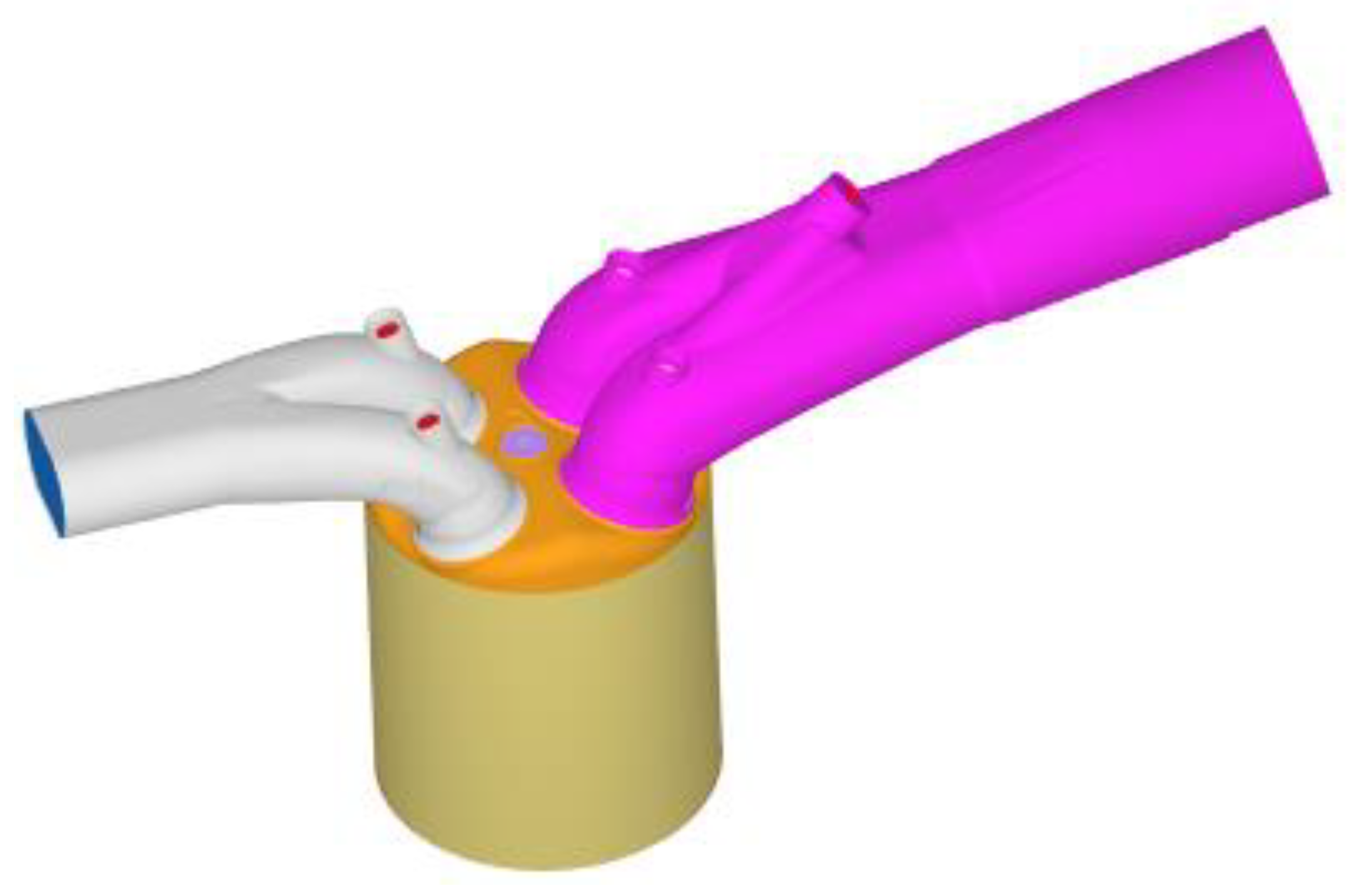
Figure 1 shows the geometry of the engine, which includes an intake port, cylinder head, spark plug, liner, piston, exhaust port, and intake and exhaust valves.
Table 1 lists the parameters of the engine configurations. The engine was converted into an H2ICE by changing the fuel from gasoline to hydrogen or hydrogen/ammonia mixture. Others were kept the same.
In the present paper, the commercial CFD software CONVERGE [
21] was used. The code features a finite-volume method. Adaptive mesh refinement (AMR) and fixed embedding were used to balance efficiency and accuracy. The real fluid model, the Redwich–Kwong equation of state, was employed. The SAGE combustion model with PRF mechanism [
22] was used for the baseline gasoline engine simulation which is capable of modeling combustion using detailed chemistry. For the hydrogen engine, a detailed H
2/air reaction mechanism [
23] was used. This reaction mechanism has been well-validated in the well-controlled laminar flame [
24,
25,
26,
27] and turbulent flame [
28] configurations. All the combustion simulations use unsteady RANS with the RNG k-ε model [
29]. Constant diffusivities were assumed, with the turbulent Prandtl number of 0.9 and turbulent Schmidt number of 0.78. Spark plug geometry was included in the simulations. In both the gasoline engine and hydrogen/ammonia engine, spark ignition was modeled using a point source with a spark timing of −15 ATDC. The base mesh size was set to 4 mm with a three-level embedding based on the temperature and velocity gradients applied to the AMR. Four- to five-level fixed embedding were used near the spark plug to better capture the ignition process [
30].
Figure 2 shows the computational mesh imposed with a temperature contour plot at −11.6 degrees ATDC, which is 3.4 degrees after spark timing. AMR based on temperature has been activated as the flame propagates away from the spark plug. For both engines, fuel injection was neglected. The intake air/fuel mixture was assumed to be perfectly mixed without consideration of the fuel injection process. With this simplification, the computational cost was greatly reduced by not having the need to model the fuel injection, droplet breakup and evaporation, and mixing. Consequently, the comparisons of the CFD results are more reliable.
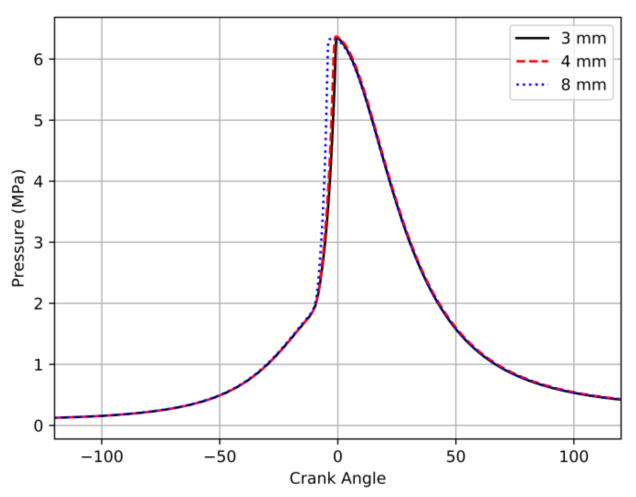
A grid independence study was conducted to verify the selected grid resolution.
Figure 3 shows a pressure against crank angle comparison of different base grid sizes of 8 mm, 4 mm, and 3 mm for a simulation using stoichiometric fuel and air mixture using a fuel blend of 70% H
2 and 30% NH
3. As shown, the result is repeated when reducing the base grid size from 4 mm to 3 mm. As such, a 4 mm base grid size is selected for the rest of this work.
3. Results and Discussions
Different global equivalence ratios and mole fractions of hydrogen/ammonia are considered.
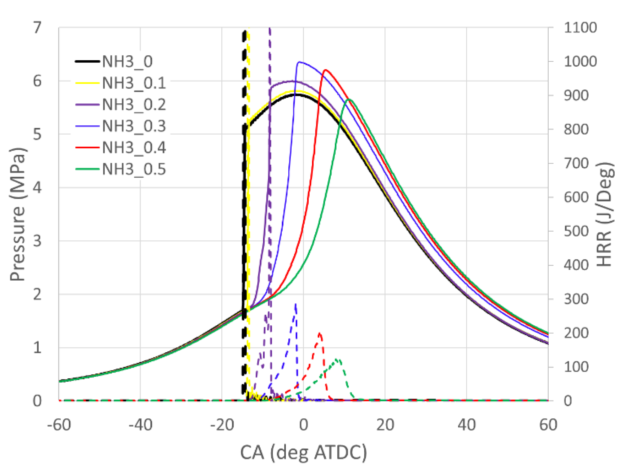
Figure 4 shows the pressure trace and heat release rate with a global equivalence ratio of 1.0 and variable ammonia volume fractions in the fuel mixture 0, 0.1, 0.2, 0.3, 0.4, and 0.5 (or, 0, 0.68, 0.785, 0.85, and 0.895 mass fractions, respectively). For the pure hydrogen combustion case and the cases with a low ammonia volume fraction (10% and 20%), evident spikes in heat release rate profiles are observed, which implies the engine knock events. Such engine knock is due to detonation from the extremely fast flame propagation of the hydrogen/air mixture [
5]. With the increase in the ammonia volume fraction in the fuel, flame speed reduces. With 30% ammonia in the fuel, the flame speed is reduced to an acceptable level and the resulting pressure trace is feasible for engine operation. Further increasing the ammonia volume fraction decreases the flame speed, reduces the peak pressure rising rate and the maximum pressure, and in-cylinder temperature. An optimal blend should contain ammonia between 30% and 40% for the present operating condition.
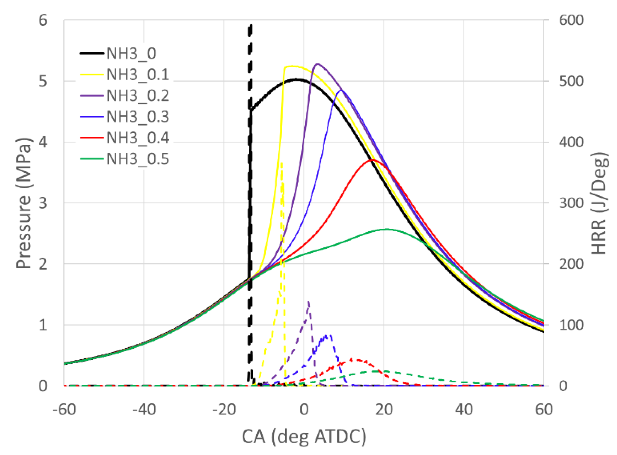
Figure 5 shows the pressure trace and heat release rate with a global equivalence ratio of 0.6. With the pure hydrogen operation, one spike in the heat release rate profile is still observed, which implies that there is an engine knock event under this condition. With 10% ammonia in the fuel, the spike is greatly suppressed. With 20% ammonia, a smooth pressure trace is achieved. By further increasing the ammonia volume fraction, the maximum pressure decreases and the combustion phasing is retarded due to slower flame speed.
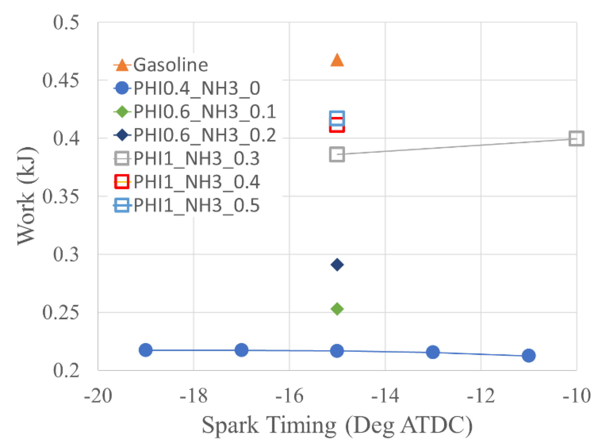
Figure 6 shows the close-cycle work of different fuels at different spark timings. The close-cycle work is the total work from IVC to EVO. The work produced by a pure hydrogen engine with an equivalence ratio between 0.4 and 0.5 is about half of the gasoline engine operating at stoichiometric combustion. Although hydrogen has a very high energy content per unit mass, its energy content per unit volume is very low. Additionally, the stoichiometric or near stoichiometric combustion of pure hydrogen is not feasible, as the super high flame speed of the premixed hydrogen/air mixture generates a detonation that leads to engine knock [
2]. Only lean combustion is feasible for a given engine size using pure hydrogen. Both of these facts limit the total energy that can be trapped in the engine. Thus, a turbocharger is required for port fuel injection H2ICE to produce the same power as a gasoline engine with the same engine size and same compression ratio [
31]. When hydrogen is mixed with ammonia, the flame speed is reduced, and the detonation-generated engine knock is suppressed. Stoichiometric combustion becomes feasible for increased peak power. In general, the close-cycle work increases with the equivalence ratio. With the stoichiometric condition and 50% ammonia in the fuel, the close-cycle work of the engine reaches about 90% of the stoichiometric gasoline engine. Spark timing also plays an important role in the work output of a spark ignition engine. An optimal spark timing is required to achieve the maximum close-cycle work that is proportional to the output power of the engine. For the stoichiometric case with 30% ammonia, the spark timing of −15 degrees ATDC is not the optimal one. According to
Figure 4, the spark timing of this case is too advanced resulting in combustion phasing too early and consequently an excessive negative work during the compression stroke. Retarding the spark timing to −10 degrees ATDC generates higher close-cycle work.
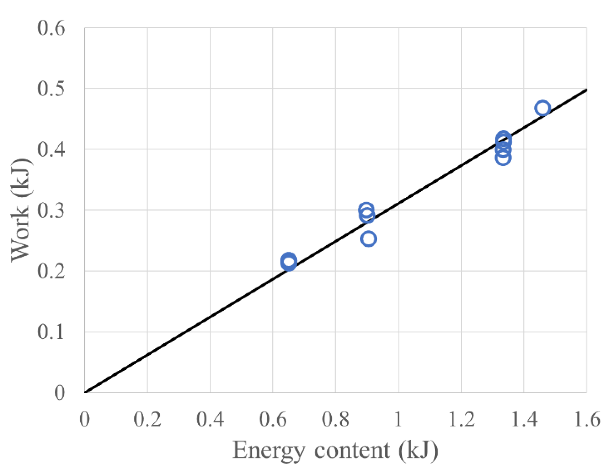
Figure 7 shows the comparison of close-cycle work and energy content of the trapped fuels. The energy content of the fuels is computed from the fuels’ lower heating value (LHV) and the mass of the trapped fuels. The LHVs for hydrogen, ammonia, and iso-octane are 240 kJ/mol, 317 kJ/mol, and 5106 kJ/mol, respectively. A strong linear correlation is observed as expected. This implies that without the limitation of the engine knock, the engine’s power mainly depends on the energy content of the trapped fuels. The ratio of close-cycle work to fuel energy content measures the thermal efficiency of the cycle. Considering the stoichiometric combustion of hydrogen, ammonia, and iso-octane with 1 mol O
2, the following is obtained:
Based on the fuels’ lower heating values, 1 mole O2 consumption corresponds to 480, 423, and 408.5 kJ for hydrogen, ammonia, and iso-octane, respectively. It implies that with the same amount of oxygen, the stoichiometric combustion of hydrogen should generate the highest amount of heat generation. This conclusion will be true for direction-injection engines, given a fixed amount of trapped air. However, this simple analysis cannot explain the phenomenon that higher ammonia fraction in the fuel results in higher close-cycle work, i.e., energy analysis based on the unit mole of oxygen is not appropriate for the present application, with port fuel injection. For the fixed boost pressure and boost temperature in the present cases, the mole number of the trapped fuel/air mixture is about the same since the volume of the combustion chamber is the same. Therefore, the amount of air trapped decreases in the order of iso-octane, ammonia, and hydrogen, given the differences in their stoichiometric coefficients. For the stoichiometric combustion of hydrogen/ammonia/air, the trapped masses of oxygen are 78.4, 79.3, and 80.2 g for cases with ammonia volume fractions of 30%, 40%, and 50%, respectively. This motivates us to conduct the energy analysis based on the unit mole number of the trapped gas mixture. Based on the fuels’ lower heating values, 1 mole of trapped gases (fuel + air) corresponds to 70.98, 69.37, and 84.40 kJ for hydrogen, ammonia, and iso-octane, respectively, assuming stoichiometric combustion. The energy content of ammonia per unit mole of the trapped gas mixture is slightly lower than the hydrogen’s but much lower than the iso-octane’s. This is consistent with the calculation of the energy content of the trapped gases. The total energy contents of the stoichiometric hydrogen with 30%, 40%, and 50% ammonia are 1.121, 1.119, and 1.117 kJ, respectively, i.e., it slightly decreases with the volume fraction of ammonia in the fuel. As a reference, the stoichiometric iso-octane/air energy content is 1.355 kJ per unit mole of mixture.
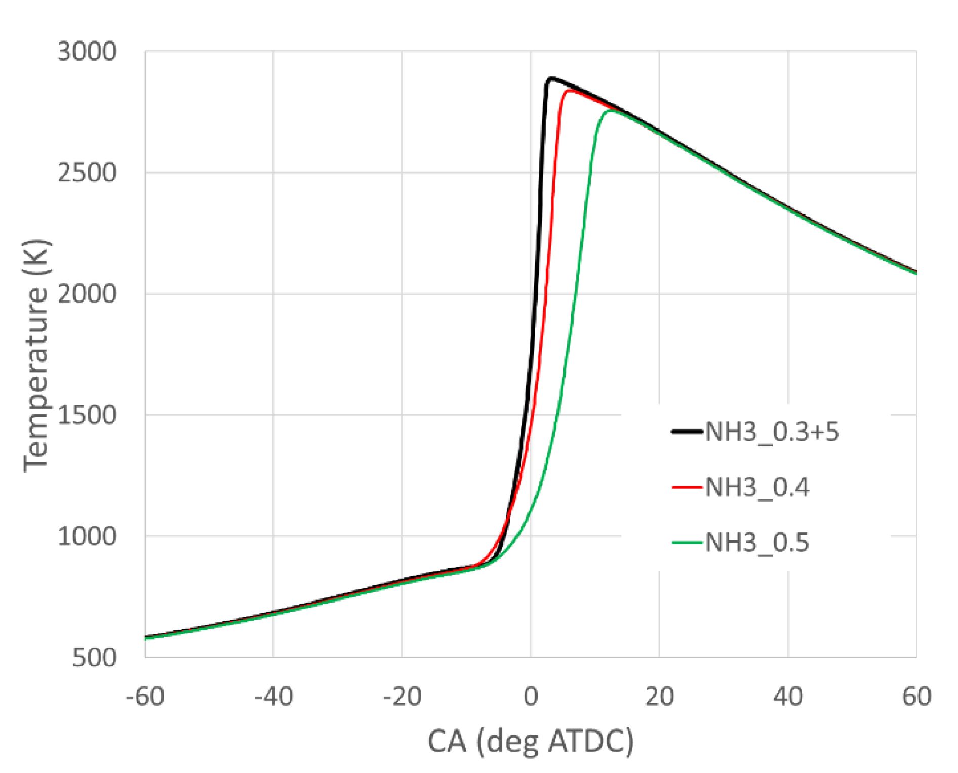
With the same equivalence ratio, close-cycle work increases with the volume fraction of ammonia in the fuel. This is not consistent with the energy contents of the fuels but can be explained by the heat loss.
Figure 8 shows the comparison of in-cylinder averaged gas temperature with different volume fractions of ammonia in the fuels. The case with 0.3 volume fraction of ammonia (black line) has a spark timing of 5 degrees retarded comparing to the other two cases. With the higher volume fraction of ammonia in the fuel blends, the flame temperature decreases. Thus, the in-cylinder averaged gas temperature is lower, which reduces heat loss through the walls of the combustion chamber and increases the close-cycle work. Therefore, with 50% ammonia in the fuel, a lower peak temperature is achieved which improves thermal efficiency.
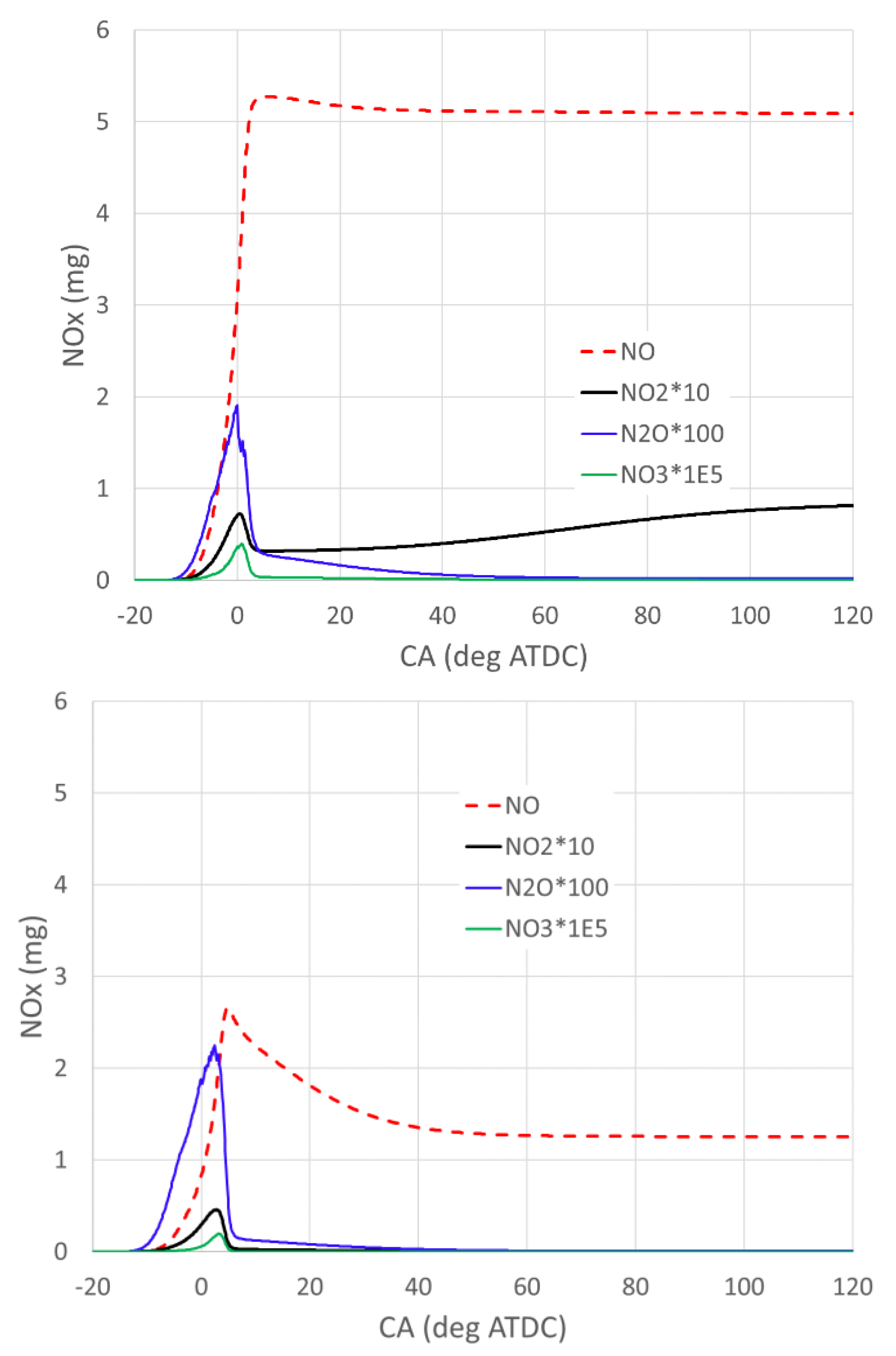
Figure 9 shows NOx emissions with a global equivalence ratio of 0.6 (top) and 1.0 (bottom). The case of a global equivalence ratio of 0.6 is with 10% ammonia in the fuel while the case of a global equivalence ratio of 1.0 is with 30% ammonia in the fuel. With a lower equivalence ratio, the formation of NO and NO
2 is much higher. This is due to the relatively higher concentration of oxygen that enhances the reactions of NO formation. The profiles of N
2O are very similar in terms of both shape and magnitude. NO emission is the dominant NO
x and the change in equivalence ratio shows a higher change in its concentration. In the following, we shall further examine the role of the equivalence ratio and ammonia addition on NO formation and consumption.
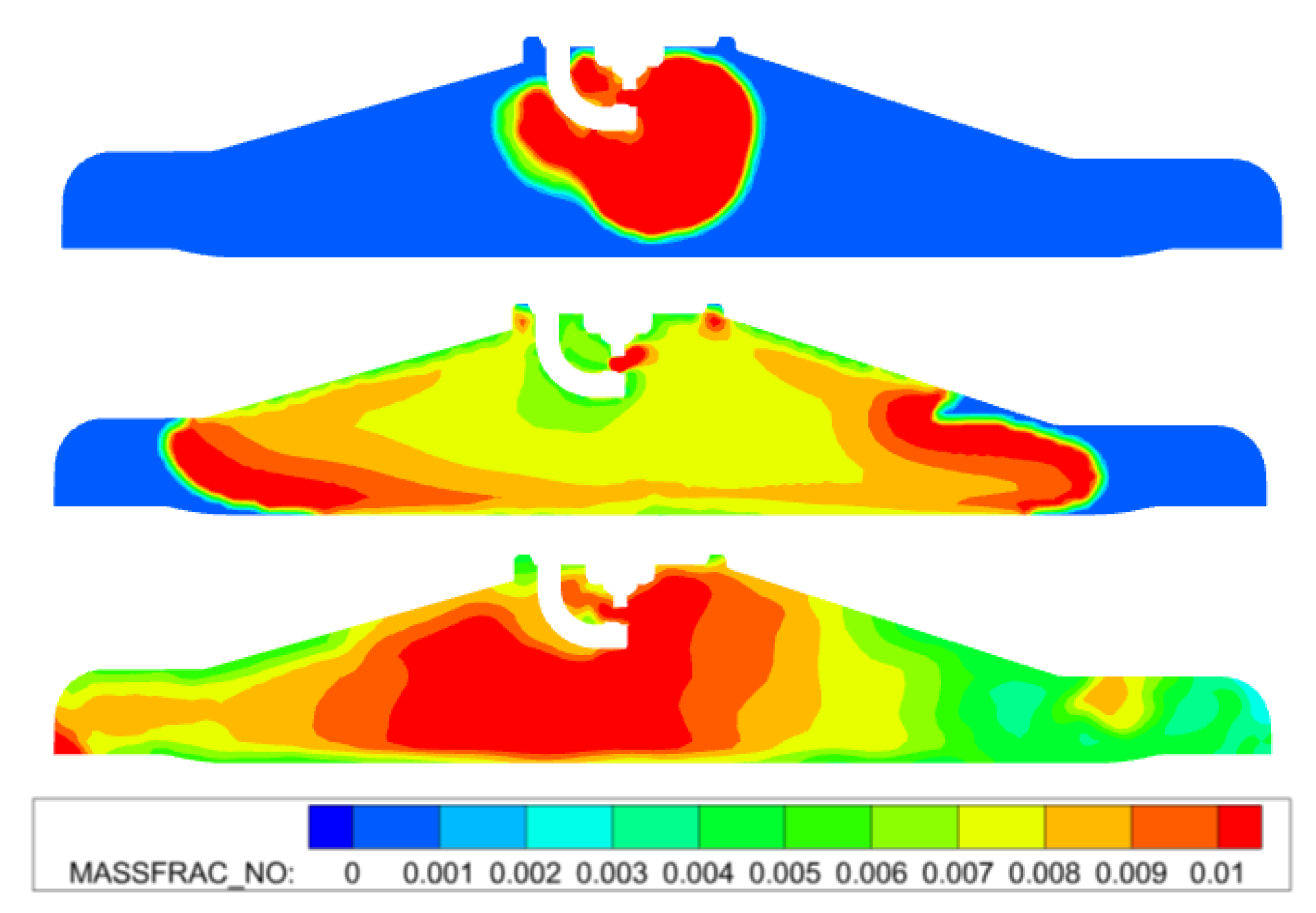
Figure 10 shows the NO distribution on the central cut-plane for the case with a global equivalence ratio of 1.0 with 30% ammonia. From top to bottom, the crank angles are −10, −5, and 0 degrees ATDC, respectively. It shows that at the early stage (−10 degrees ATDC), NO is formed within the burned region. Later, at −5 degrees ATDC, the NO is then largely consumed in the burned region. A high concentration of NO is observed on the flame front. This is due to the existence of ammonia in the mixture. Through the following reactions,
NO can be converted to nitrogen or N
2O. This explains the decrease in total NO in the combustion chamber, as shown in
Figure 9.
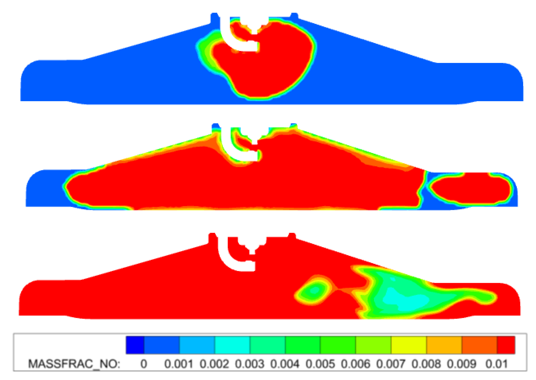
Figure 11 shows the NO distribution on the central cut-plane for the case with a global equivalence ratio of 0.6 with 10% ammonia. From top to bottom, the crank angles are −11, −7.4, and −3 degrees ATDC, respectively. These timings have about the same burning rate as the ones in
Figure 10 for a fair comparison. At −11 degrees ATDC, the NO distribution of this case is very similar to the one of the stoichiometric case (cf. the top of
Figure 10). However, at −7.4 degrees ATDC, the concentration of NO at the burned region is still very high. It implies that very little NO is converted to nitrogen by ammonia due to the relatively low ammonia concentration. Therefore, the total NO in the combustion chamber is approximately constant after it reaches its maximum (c.f.,
Figure 9 top). This behavior of NO formation is very similar to the ones in the combustion of hydrocarbon fuel [
32] and pure hydrogen [
5].
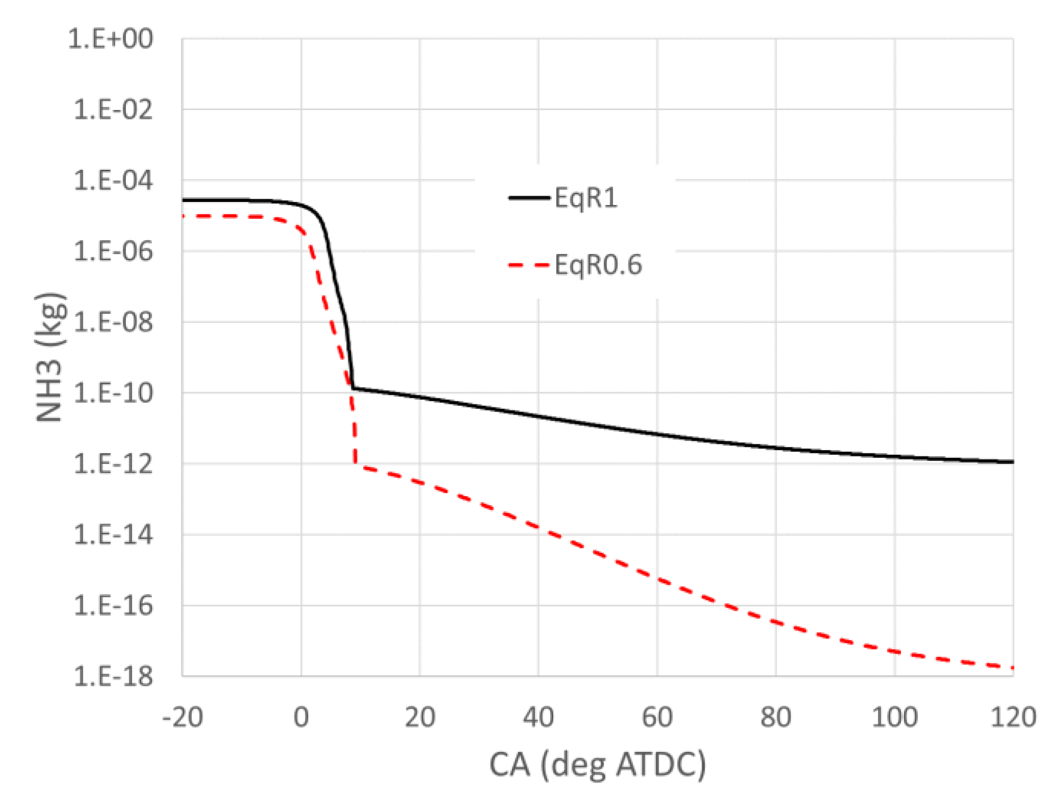
Figure 12 shows the engine-out emissions of ammonia with different global equivalence ratios. In general, ammonia emission is negligible. Relatively, the ammonia emission under high equivalence ratio conditions is higher than the low equivalence ratio conditions, about six orders of magnitude higher. The consumption of ammonia clearly shows a two-stage phenomenon. The majority of the ammonia is consumed during the main combustion. After the main combustion, the consumption of ammonia becomes very slow. It should be mentioned that the crevice volume is not considered in the present simulations. For port fuel injection or manifold fuel injection, it is inevitable that some of the ammonia is trapped in the crevice volume and cannot be burned completely. It might significantly increase ammonia emissions.


