Article

Attitude-Oriented Stability Control with Adaptive Impedance Control for a Wheeled Robotic System on Rough Terrain

1
Key Laboratory of Vehicle Advanced Manufacturing, Measuring and Control Technology, Ministry of Education, Beijing Jiaotong University, Beijing 100044, China
2
School of Automation, Beijing Institute of Technology, Beijing 100081, China
*
Author to whom correspondence should be addressed.
Machines 2023, 11(6), 650; https://doi.org/10.3390/machines11060650
Submission received: 1 May 2023 / Revised: 22 May 2023 / Accepted: 12 June 2023 / Published: 15 June 2023
(This article belongs to the Section Automation and Control Systems)

Abstract

:
Base stability for a wheeled robot while driving over rough terrain is a challenging issue. This paper proposes a novel base-stability control framework, consisting of an AVIC (adaptive variable-impedance control), AVIC-based tracking controller, and a THV (terrain height variation) and AC (attitude control) AC-based controller to stabilize the base on rough terrain. The AVIC-based controller aims to track the desired trajectory of the robot base while suppressing lumped disturbance, including system uncertainties in the internal dynamics and unknown external disturbance. The THV-based controller is utilized as a feedforward controller to improve posture tracking performance in order to achieve a horizontal posture. The AC-based controller is employed to maintain the horizontal posture of the base. The effectiveness and robustness of the proposed controllers are validated by a series of numerical trials, and the results are evaluated.

1. Introduction

Maintaining a stable base while a rover drives over rough terrain is an underlying requirement in many real-world applications [1,2,3,4], such as payload delivery and disaster rescue to avoid payload damage. However, the rover can easily lose stability, since it does not have an active stabilization system to compensate for disturbances from rough terrain [5]. It realistically cannot fulfil many real-life application tasks due to the lack of stabilization of the objectives. Therefore, suppressing disturbances and holding a horizontal, stable position are of great importance for the rover to operate a carrying task stably [6,7].
Many study attempts have been made to stabilize the base by utilizing control methods to hold a horizontal pose [8,9,10]. Grand [11] proposed the posture-decoupling control method to handle disturbances from the terrain during robot motion, and treat the legs as an active suspension system to adapt to terrain fluctuations, thereby ensuring the stability of the body. Similarly, Besseron [12] utilized a decoupling control method based on kinematics to maintain the stability of the robot in the process of movement. The posture of the body is adjusted by PD through the rotating joints installed on the body [13]. The literature combines PI control and compensation control to control the posture of the wheelchair chassis, and this control method also improves the wheelchair’s obstacle-crossing ability [14]. The work [15] calculates the current robot-leg-position control by comparing the angle of change between the current posture and the expected posture, and combining it with the distance from the landing point, in order to achieve stable control of the robot body during wheeled motion. Lim et al. [16] designed a two-wheeled humanoid robot, DRC-HUBO+, which needs to change its configuration when switching from walking mode to wheeled mode. When in wheeled locomotion, the robot is in a kneeling position with a lower center of gravity and a larger area of supporting polygons than in walking mode, thereby improving the stability of the body. Gronowicz et al. [17] presented a novel solution of a wheel-legged robot equipped with a specially designed limb kinematic system; moreover, an idea of the posture-control system design was sketched and selected results of the tests conducted on the robot prototype were reported. The experimental results showed that the robot has two motion modes of gait driving and wheel driving. Grand et al. [18] proposed a general kinematic model with decoupling of the posture control and trajectory tracking. The model was applied to motion control and the experiment showed the ability of the control algorithm to maintain a certain posture with a small error on pitch-and-roll angles when revolving on an unknown irregular terrain. Ni et al. [19] proposed a posture control framework for a wheel-legged robot to adapt to the uncertainty of parameters with good posture-control performance and low-parameter sensitivity. Jiang et al. [20] provided a passively-actively transformable wheel-legged robot that can traverse on unstructured terrain, and the simulation results showed that the posture of the robot was well controlled. With the two linear actuators far away from the joints, the carrying capacity and posture-control stability are enhanced. However, the above works are kinematics-based efforts, which demonstrate a lack of consideration for dynamics-based control. Only focusing on the kinematics effort, one is likely to ignore the dynamics action, including inertia, so that the robot has difficulty stabilizing.
Making dynamics-based efforts is also an effective way to maintain the stable base [21,22,23]. As seen in the work [24], an automatic-balance control algorithm is proposed, which optimizes the ground forces acting on the excavators to achieve the smooth operation of the body while moving on uneven terrain. Reference [25] adjusted the center of mass of the robot by modifying the ground forces on each leg, thereby improving its motion stability and obstacle-crossing ability. Du [26] proposed an overall dynamic-motion method to set the desired motion trajectory and to obtain the angular acceleration produced by each wheel and the torque-control measurement of each driving joint through the inverse dynamic solution, so as to realize the stable driving control of the robot. Hyon [27] devised a stable attitude-control method to perform dynamic control on the hydraulic-driven robot body as a whole and to optimize joint torque distribution. Literature [28] used a state observer with a gyroscope and inclinometer to estimate the roll angle and pitch angle of the robot, and formulated the target contact force of each wheel according to the posture and speed of the body to achieve active-contact force control of the foot by manipulating joint torque. Reid et al. [29] established a velocity kinematics model for the quadrupedal robot and introduced ground-contact constraints to solve the active compliance problem of maintaining a stable posture when the robot traverses unstructured terrain. This algorithm uses RGB-D sensors to generate a terrain point cloud in front of the robot, and from this, identifying the contact position of the wheels and solving the limb-joint angle. In order to accurately detect terrain, the robot can only advance at a speed of 7.5 cm per second. Literature [30] designed an overall motion-planning and control framework for a quadrupedal robot. This framework closely combined the additional degrees of freedom brought by the wheels. It constantly updated the reference track using the zero-torque point idea, which can optimize the position, speed, and contact force of the wheels, and facilitate the quadrupedal robot’s function of quickly sliding forward with the help of the wheels while walking across obstacles with its leg. However, these works focus on the force distribution from the base to the attainment of force equilibrium in real time. However, this is a static equilibrium for dynamic movement, in which instability can easily occur.
To address these problems, a base-stability-control framework is proposed for a novel wheeled robotic system, to stabilize the base while driving over rough terrain. The proposed framework allows the robot’s base to track the desired force by utilizing the AVIC, as well as to hold a horizontal base’s posture by rendering the terrain sensing information as a feedforward control. These methods can effectively suppress the disturbances and stabilize the base by the proposed control framework by both tracking the desired force and keeping the base’s posture, which is different from the current work focusing on the point of view. The main contributions of this paper are summarized as follows:
(1)
To minimize the forcetracking error, the AVIC controller is employed to track the desired force of the robot’s base by the proposed adaptive control law to compensate for the uncertainty.
(2)
In addition, the THV controller is devised as a feedforward control to minimize the force-tracking error, as well as maintain the robot’s base horizontal posture, which makes up for the limitation in taking care of the stability and the horizontality.
(3)
A series of numerical trails with the proposed control framework are conducted in a novel wheeled robotic system. The effectiveness of the framework is validated and evaluated with the comparative results using the current control methods.
The rest of this paper is organized as follows: in Section 2, the novel wheeled robotic system objective-tracking system composition is presented. Section 3 introduces a novel control framework for the robot system, consisting of adaptive force-tracking control and posture-oriented control. This control framework is verified by a series of simulations in Section 4. Finally, the main contributions and discussion of directions for future work are presented in Section 5.

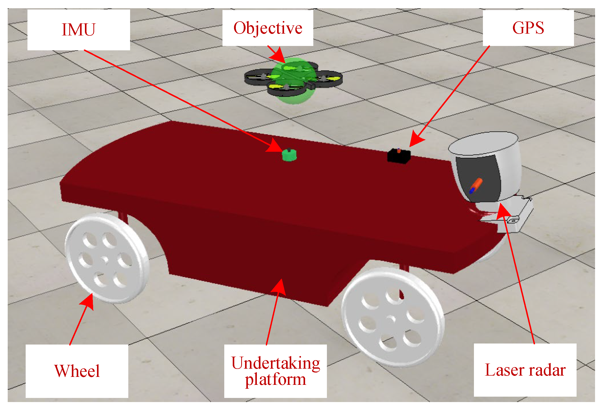
2. System Composition

To reach the purpose of rapidly and compliantly tracking objective, a novel wheeled objective-tracking system is devised to undertake the UAV and avoid falling down on the rough terrain due to the lack of power supply, which is shown in Figure 1. The length, width of the robot is 1.2 m, 0.8 m. The maximum steering angle of every wheel is 45 ° . The novel wheeled UAV-tracking system is made up of the undertaking platform, GPS, and laser radar. This tracking system is capable of rapidly tracking the objective by the UGV of the independent drive and steering utility, and of undertaking the objective. GPS provided the position information for the robotics system, and the position accuracy is 1~2 m. LIDAR gives the distance information to the robotics system. The maximum position accuracy is 1 mm. Every wheel is contacted by the electrical cylinder with the robot’s base. The electrical cylinder acts as an active suspension system to adjust the length of the unit for control the orientation of the base. The maximum speed of the wheel is 3000 rpm.
The robot control system adopts a distributed control scheme, mainly consisting of a main control computer and four sub controllers. The main controller adopts the ROS (Robot Operating System) system, and the sub controllers adopt the Linux system, meeting the real-time and scalability requirements of control and fully utilizing the controller performance. Among them, the main controller is a high-performance computer that mainly handles three tasks: (1) after receiving the environmental information (i.e., terrain height with respect to robotics system) collected by the upper level environmental perception through UDP communication, the information is processed and decisions and motion control are made; (2) the ground reaction force and robot’s base posture are collected from the four wheels and the robot’s base, respectively. This information is processed by the host computer. In addition, the position, speed, and acceleration control values of each wheel during movement is calculated and sent to each wheel controller for control through UDP communication; (3) Receive control instructions from remote control or computer, analyze the instructions, and send control instructions to each sub controller. The current motion status of the robot, such as the current position, speed, acceleration, body posture information, and force on each leg and foot, will be transmitted to the remote computer through wireless WIFI through tasks within the main control computer to achieve real-time monitoring of the robot’s motion status. The computer can also send control commands to the main controller, such as the expected motion speed and acceleration of each wheel, desired attitude angle, etc.

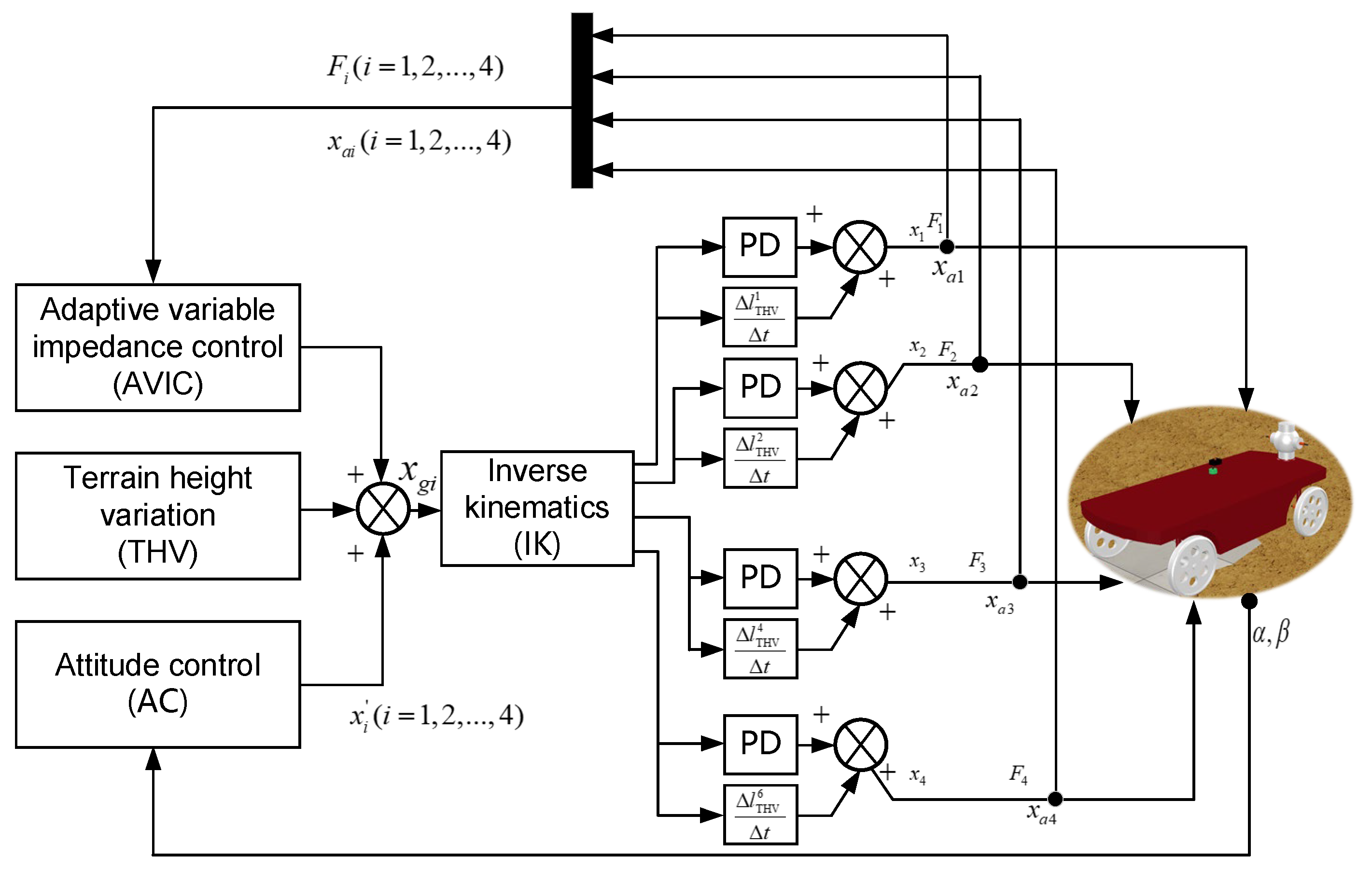
3. Base Stability Control Framework

The proposed control framework aims to render the stable and horizontal base for the wheeled robotics system on the rough terrain. It is composed by AVIC-based, AC, and THV-based controllers, as shown in Figure 2. The AVIC-based controller is employed for the base of the robotic system to track the desired force such that the base can avoid the instability that occurred by the force-tracking error. The AC and THV controllers aim to maintain the base’s posture through posture decoupling and using the terrain height as the feedforward control. Finally, the control quantity of the AVIC, THV, and AC is transmitted to the inverse kinematics (IK) to calculate the control input of each wheel, and then control the wheels by using PD controller.
When a robot moves on unstructured terrain and does not obtain terrain information through an environmental perception system, each wheel of the robot is easily disturbed by unknown terrain. If each wheel cannot suppress this disturbance in a timely manner, it will lead to unstable phenomena such as tilting and shaking of the body, thereby weakening the robot’s survival ability in unknown unstructured environments. AVIC, THV, and AC controllers ensure smooth interaction between the wheels and the unknown external environment, eliminate leg force-tracking errors caused by unknown environmental information, and ensure the stability of the robot body.

3.1. Adaptive Force Tracking Control

To suppress the disturbance and track the desired force, the AVIC force-tracking control method is proposed to minimize the force-tracking error. Instead of the traditional control method that focuses on adjusting the impedance parameter, the proposed control method compensates the uncertainty of the system by the devised control law. The differential equation of the error can be expressed as
m d e ¨ + b d e ˙ + ( k d + k e ) e = m d f ¨ r + b d f ˙ r + k d f r k d ( m d x ¨ e + b d x ˙ e )
where force error e = f r f e is the difference between the reference force f r and environment force f e , m d , b d , k d represent the mass matrix, damping matrix, and stiffness matrix of the desired impedance model, respectively. The second-order dynamics is based on the expression of the mass-stiffness-damping system m d ( x ¨ r x ¨ ) + b d ( x ˙ r x ˙ ) + k d ( x r x ) = f e , where x r and x are the reference position and current position. Here, the control law can be written as
Δ x = ε ( t ) e ˙ ( t ) + σ ( t ) e ( t ) + ψ ( t )
where e ( t ) is the error between desired force f d and action force f e . ψ ( t ) represents the auxiliary function with time varying. ε ( t ) ,   σ ( t ) stand for the time-varying coefficient. Substituting Equation (2) into Equation (1), we have
e ¨ + b d + k d k e ε ( t ) m d ε d ( t ) e ˙ + k d + k e + k d k e σ ( t ) m d σ d ( t ) e =   k d k e m d [ m d k d x ¨ e + b d k d x ˙ e + x e ψ ( t ) ] + m d f ¨ r + b d f ˙ r + k d f r m d ψ d ( t )
where the varying parameter of above force-error equation can be defined as ε d ( t ) , σ d ( t ) , ψ d ( t ) . In addition, let E b = [ e b e ˙ b ] T . The error function of Equation (3) can be rewritten as
E ˙ b ( 0 1 σ d ( t ) ε d ( t ) ) Γ ( t ) E b ( 0 ψ d ( t ) ) Ψ ( t ) = 0
Similarly, let Γ ( t ) , Ψ ( t ) be as the parameter matrix of Equation (4) of the state equation. To clearly describe the state of the force-tracking state, let E e = ( e b e e ˙ b e ˙ ) be as the state vector of the total error equation of state. The new error equation of the state vector reference model of the total error state equation and the actual force error model of the system can be expressed as
E ˙ e ( 0 1 b m a m ) Γ m ( t ) E e ( 0 0 σ d ( t ) b m ε d ( t ) a m ) ( e e ˙ ) + ( 0 ψ d ( t ) ) T ( t ) = 0
To ensure that the closed-loop adaptive system is stable in the sense of Lyapunov, the control law can be given as
{ σ ˙ d ( t ) = μ 3 λ x ˙ ( t ) ξ 3 σ ( t ) ε ˙ d ( t ) = μ 2 λ e ( t ) ξ 2 ε ( t ) , ψ ˙ d ( t ) = μ 1 λ ξ 1 ψ ( t )
where λ = λ p e ( t ) + λ v x ˙ ( t ) is the variable parameter. ξ 1 , ξ 2 , ξ 3 are the correction factor. μ 1 , μ 2 , μ 3 are the positive integer.
To validate that the closed-loop adaptive system is stable, the Lyapunov energy function V ( E e , t ) is established as
V ( E e , t ) = 1 2 E e T P E e + 1 2 Z T R Z   = 1 2 E e T P E e + 1 2 β 0 ( b p ( t ) b m ) 2 + 1 2 β 1 ( a p ( t ) a m ) 2 + 1 2 β 2 w p ( t ) 2
where Z = ( b p ( t ) b m a p ( t ) a m w p ( t ) ) , R = ( β 0 β 1 β 2 ) , P = ( p 1 p 2 p 2 p 3 ) . β 0 , β 1 , β 2 are positive constant. The derivative of above function can be written as
V ˙ ( E e , t ) = 1 2 E e T Q E e + ( ε d ( t ) b m ) ( λ e + β 0 ε ˙ d ( t ) )   + ( σ d ( t ) a m ) ( λ e ˙ + β 1 a ˙ p ( t ) ) + ψ d ( t ) ( β 2 ψ ˙ d ( t ) λ )
To ensure stability, the derivative of the energy function should meet the requirement. Thus, taking Equation (6) into Equation (8), we can obtain V ˙ ( E e , t ) 0 in terms of μ 1 , μ 2 , μ 3 and σ 1 , σ 2 , σ 3 are all positive constants, and they belong to ( 0 , 1 ] .

3.2. Posture-Oriented Control
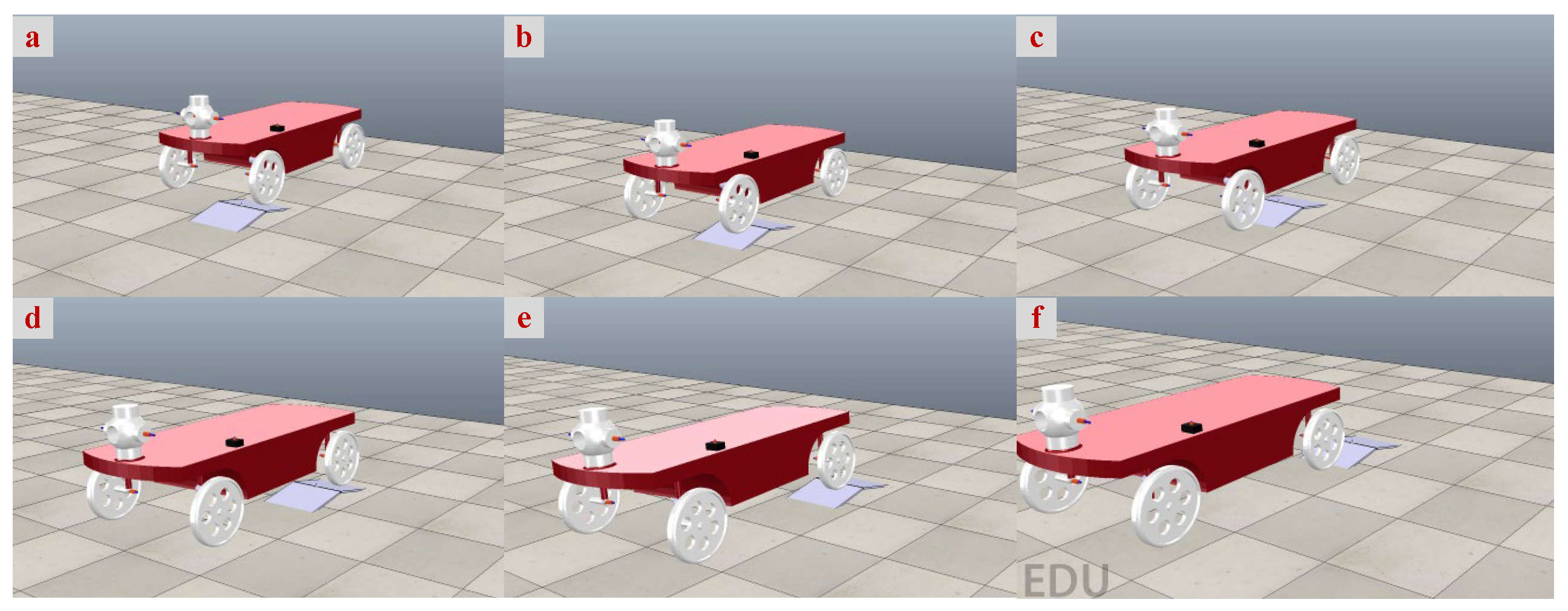
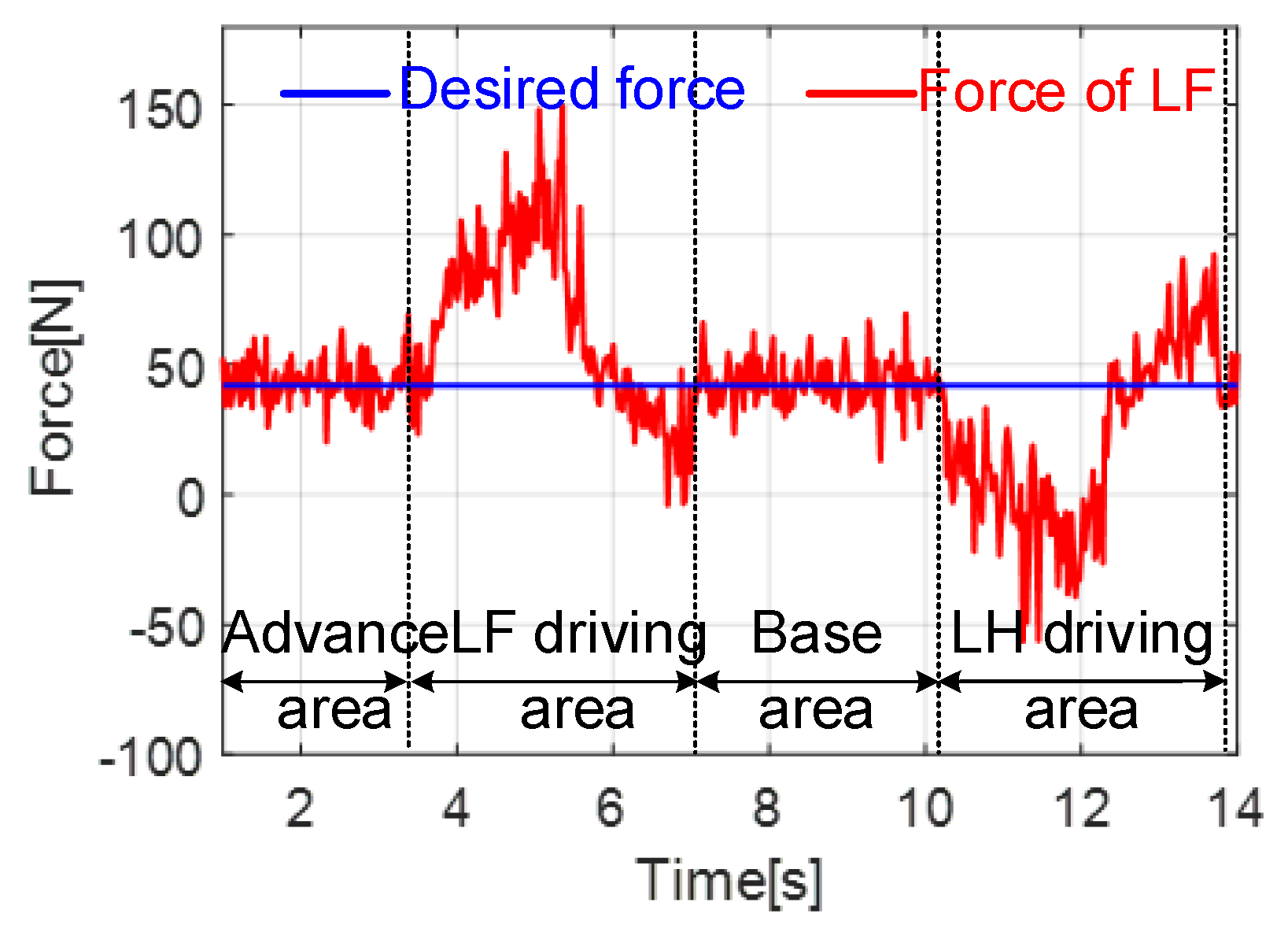
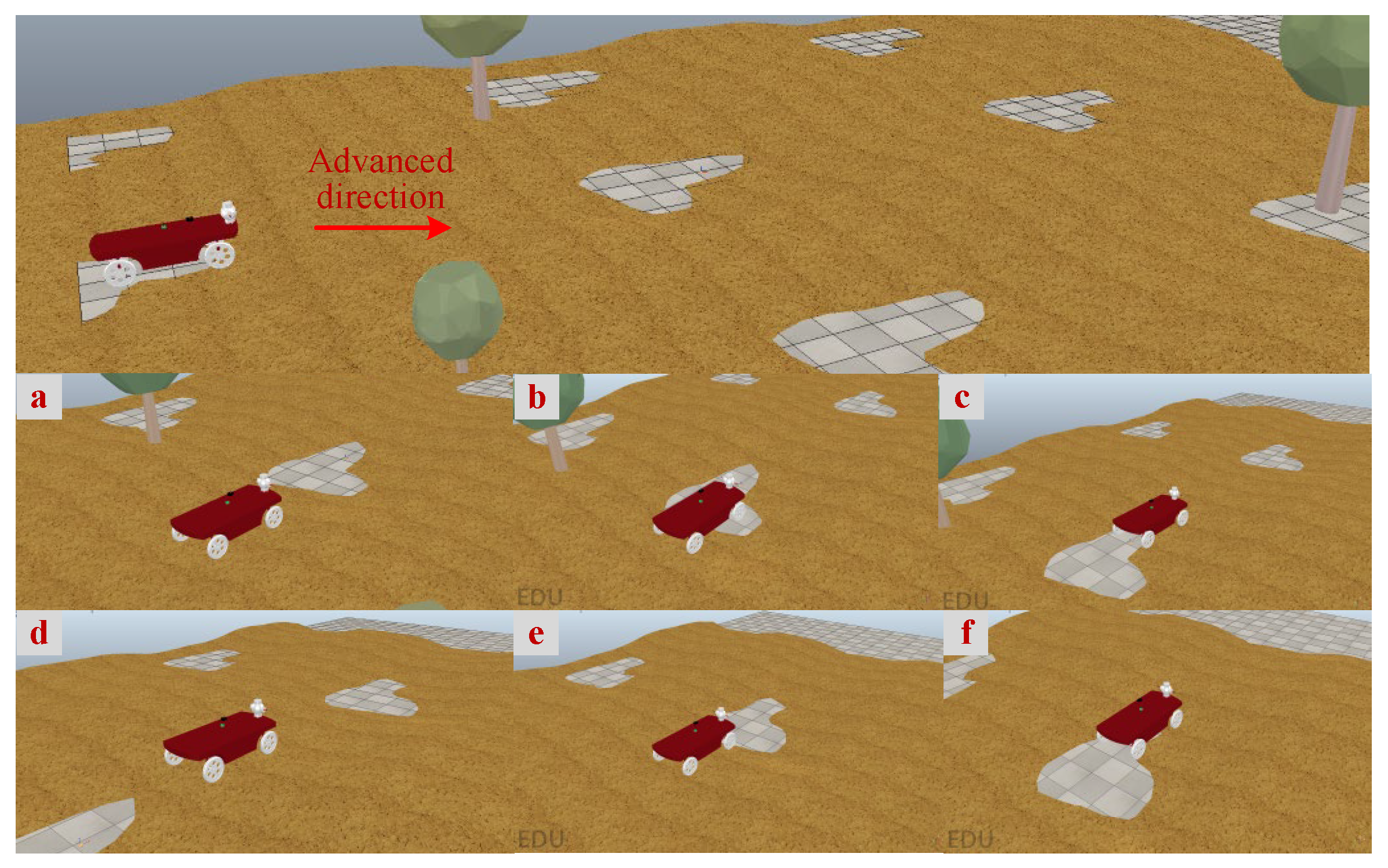
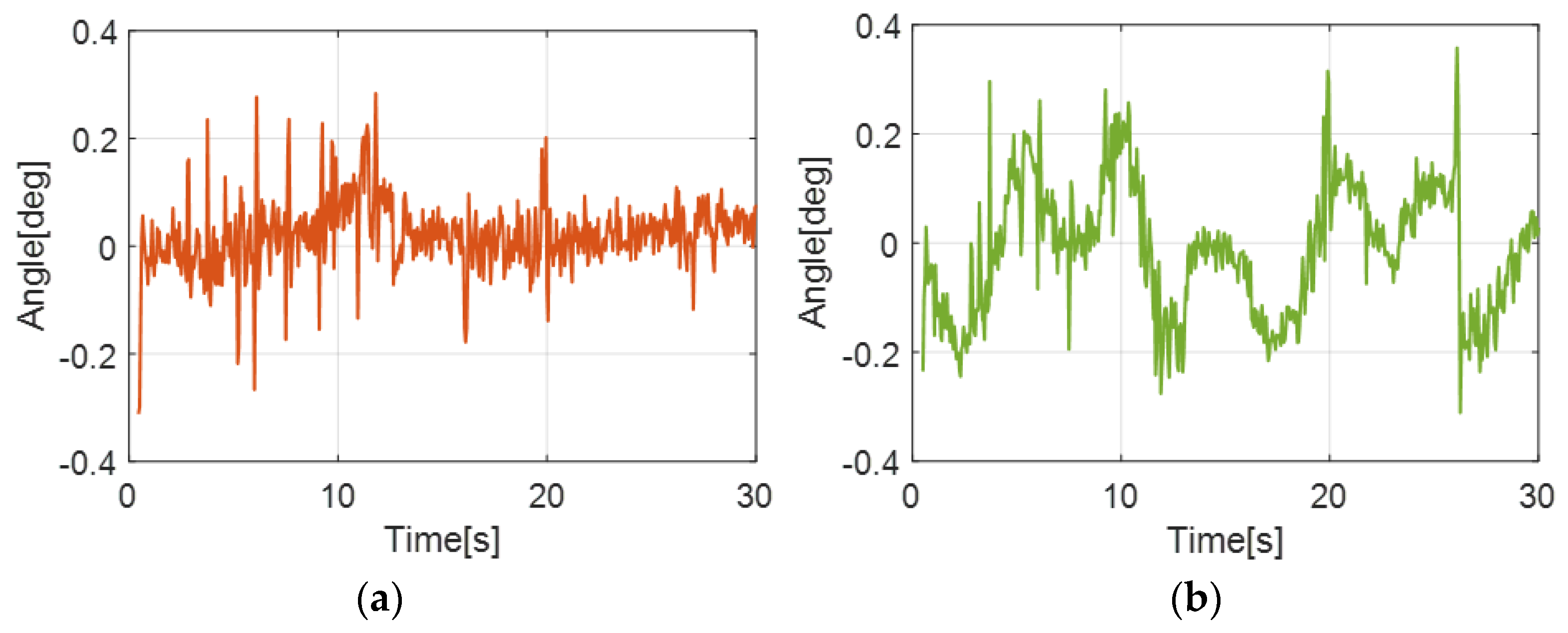
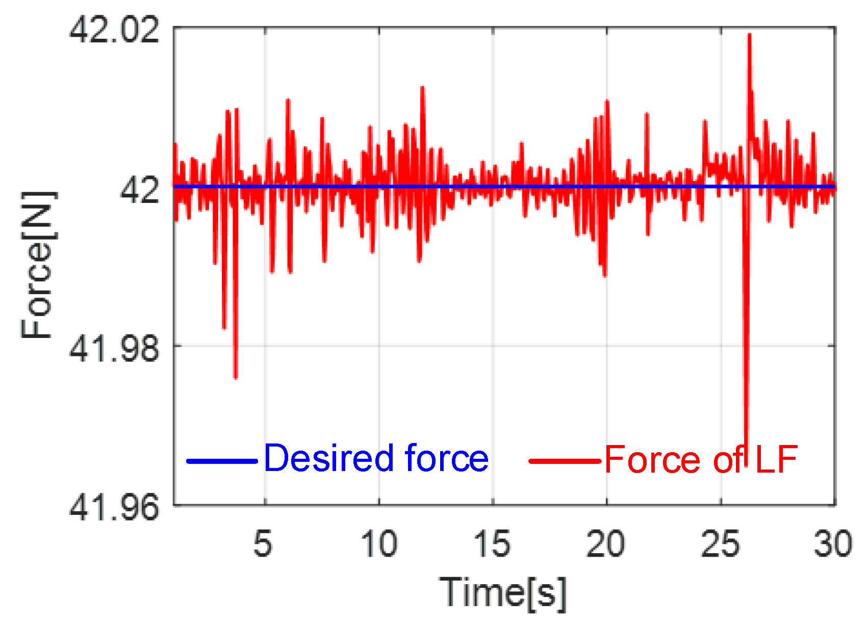
To undertake the UVA, keeping the horizontal posture of the base is important of the robot. First, let H j E ( h j x , h j y , h j z ) , j = 1 , 2 , , 6 be the position of the hinge point in platform frame { E } . The position vector of every actuator can be expressed as
l j = T H j E + r b j
where r ( x , y , z ) is the origin of the hinge frame with respect to the lower platform frame { L } , b j ( b j x , b j y , b j z ) is the hinge point of the undertaking platform, T ˙ = θ ˙ x A z A y S i A x + θ ˙ y A z S j A y A x + θ ˙ z S k A z A y A x , S i , S j , S k are the skew-symmetric matrices, and T represents the transform matrix from frame { E } to frame { L } , which is depicted as
T = A ( θ x ) A ( θ y ) A ( θ z )   = [ C θ z C θ y C θ y S θ z S θ y S θ x C θ z S θ y + C θ x S θ z S θ x S θ y S θ z + C θ x C θ z S θ x C θ y S θ x S θ z S θ y C θ x C θ z S θ y S θ z C θ x + S θ x C θ z C θ x C θ y ]
where A ( θ ) represents a positive rotation of θ about the n-axis, θ x , θ y , θ z are the roll, pitch, and yaw of leg-wheel, and C θ , and S θ are defined as cos   θ and sin   θ , respectively. The length of every wheel can be expressed as
l j = ( T 11 h j x + T 12 h j y + T 13 h j z + x b j x ) 2 + ( T 21 h j x + T 22 h j y + T 23 h j z + y b j y ) 2 + ( T 31 h j x + T 32 h j y + T 33 h j z + z b i z ) 2
The wheel j position can be depicted as
l i , j c m d = l i , j i n i t i a l + l i , j
Thus, the control of the robot’s base is expressed through the above equations. Additionally, the first and second derivative of the position of the wheels are the outputs of the robot posture decoupling controller, which are to be sent out to the controller of the wheels to execute control task on the rough terrain.

4. Numerical Trials

4.1. Numerical Setup

To validate the proposed control framework of accurate existing compliance-tracking the objective on the rough terrain, two scenarios that featured various slopes and unknown terrain in the numerical trials were conducted. The main parameters of the robot in the simulation are same as the real environment. Two large slopes with 95   ×   25 cm, two small slopes with 20   ×   10 cm, one conical slope with 35   ×   15 cm, and one large slope with a dip of 15 degrees are set in scenario 1 to verify the performance of the system. The material of the slopes is set as rubber, and the stiffness of it is configured to 100. Moreover, the unknown environment with variable geometry terrain is also employed to validate the effectiveness of the proposed control method.
The host controller is applied for real-time control of the robot. The other four controllers are sub-controllers that regulate the position, speed, acceleration of the four wheels, and the suspension system, respectively. The communication between controllers is via UDP, and the cycle is 3 ms. The posture data are acquired by the inertial measurement unit (IMU) installed on the robot’s trunk via RS-422 per 1 ms. In addition, the host computer receives the posture information and then manages it. The four force sensors mounted on the end of each wheel transmit the force information (i.e., ground reaction force) with the host computer via RS-485 per 2 ms. The force value of each wheel is obtained by resolving the sampled force information from each force sensor. LF, RF, RH, and LH represent left fore, right fore, right hind, and left hind unit, respectively.

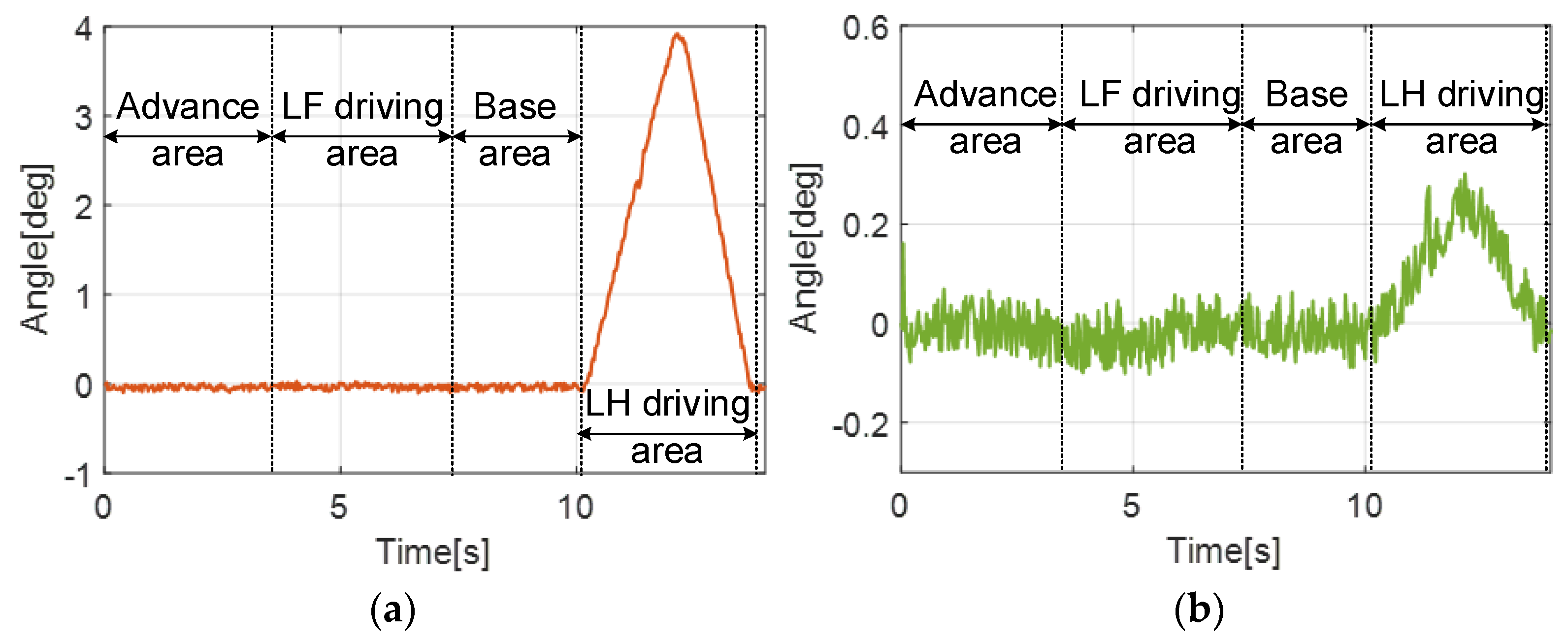
4.2. Variable Terrain of Slopes

Scenario 1: In this part, the robotics tracking system drives over the variable terrain to hold the horizontal posture of the undertaking platform and reach the desired force of 42 N by utilizing the adaptive force tracking control and posture-oriented control. The speed of the robotics system is given to 0.3 m/s. The maximum height of the large slope is 8 cm. The performance of the robotics system on tracking and holding desired objectives is shown in Figure 3. In this case, the ability to handle single changes in roll and pitch is tested. When the robot moves onto varying terrain, the wheels should actively adjust their length to compensate for the change in the base’s posture. The initial height of the base is 54 cm. The mass m d , damping b d , and stiffness k d in the AVIC method are 1, 0.8, and 1.4, respectively. The correction factors ξ 1 , ξ 2 , ξ 3 are 0.8, 0.4, 0.7, respectively. In addition, the positive integer μ 1 , μ 2 , μ 3 are 0.9, 0.9, 0.6, respectively. According to the designed terrain, LF and LH will encounter the slope in order, which would change the base’s roll and pitch. Therefore, we expect that LF is able to detect the slope through the proposed control framework without the environment awareness system and adapt to the obstacle. The simulation is disclosed as follows.
As shown in Figure 3, the whole driving process above is divided into six parts. Each part is the result of the local magnification in the whole process. In addition, the posture of the undertaking platform is always kept in the horizontal level rather than confirming the attitude with the variable geometry terrain. The tracking force of the platform is also handled in the reasonable range, such that the platform does not generate vibration in the driving process. The detailed performance of the robotics system is also illustrated in Figure 4 and Figure 5.
In the whole process, the attitude angles (roll and pitch) are always maintained at 0.15 0.14 ° by using the AVIC-based and THV-based method for LF wheel. For instance, the robotics system encounters the slope that is shown in Figure 3a. The roll angle of the undertaking platform tends to the 0.15 ° , but falls back to 0.05 ° rapidly due to the action of the posture-oriented control. Additionally, in other parts of the whole process, the roll angle is aways handled on the reasonable range, even if some transient mutations occur in the process. Conversely, the roll angle during the time of 9.8 13.8 s tends to a maximum of 4 ° due to not using the proposed method for the LH wheel. In addition, the pitch angle also approaches to the desired range ( 0.1 0.3 ° ) such that the undertaking platform can keep the horizontal posture while robotics system is driving over the rough terrain. Additionally, the force information from the simulation is shown in Figure 5.
In this scenario, the desired force of 42 N is set. Thus, the purpose of the robotics system is to track the desired force, which aims to compliantly undertake the UGV and avoid the subversion of it. As shown in Figure 5, the force of the platform is always maintained between 38 150 N. Especially in the process of Figure 3d, the force suddenly increases to 150 N (which can be observed at the 5 s time point in Figure 5) but rapidly falls back to the boundary of the desired value. Additionally, at the other parts, the desired force of 42 N is tracked accurately by using the ACIV-based method.

4.3. Reality-Like Terrain

Scenario 2: Further, the unknown and reality-like terrain is conducted to validate the effectiveness of the proposed control methods. In this section, the same speed of 0.3 m/s for the robotics system is to be configured. The relief height of the terrain is absolutely unknown such that the performance of the proposed control methods can be validated effectively. The mass m d , damping b d , and stiffness k d in the AVIC method are 1, 0.8, and 1.4, respectively. The correction factors ξ 1 , ξ 2 , ξ 3 are 0.7, 0.5, 0.5, respectively. In addition, the positive integer μ 1 , μ 2 , μ 3 are 0.85, 0.7, 0.7, respectively. The process of the robotics system traversing the terrain is shown in Figure 6. According to the designed terrain, LF, RF, RH, and LH will encounter the variable terrain, which would change the base’s roll and pitch. Similarly, the performance of the proposed control framework is validated in this scenario to adapt to the environment. The simulation is disclosed as follows.
Similarly, the process of robotics system traversing the reality-like terrain is divided into six parts in Figure 6, where each of the parts represent the local magnification. From the whole traversing process, the above part of the undertaking platform always confirms with the variable terrain. Additionally, the vibration problem of the platform does not generate by the force-tracking error. To clarify in detail the performance of the control methods, the posture and force information are given in Figure 7 and Figure 8.
In this reality-like terrain, the roll, pitch angle is kept between 0.3 0.3 ° by utilizing the proposed control methods. For instance, at the time of 5 s, the roll angle of the undertaking platform tends to the 0.3 ° , but it falls back to 0.1 ° rapidly due to the action of the posture-oriented control. In addition, the pitch angle also approaches the desired range of 0.3 0.4 ° , which leads to maintain the platform’s horizontal posture. Additionally, the force information from the simulation is shown in Figure 8.
As shown in Figure 8, the desired force of 42 N is also set in this reality-like terrain. The real tracking force of the platform is always maintained between 41.97 42.02 N. Especially in the process of Figure 6e, the force suddenly decreases to 41.88 N (which is illustrated at the time point 25 s of Figure 8) but rapidly falls back to the boundary of the desired value. For the other parts, the desired force of 42 N is accurately tracked by utilizing the adaptive force-tracking method.
Furthermore, the reference force tracking is also evaluated through the proposed control framework, which is depicted in Figure 2. As for AVIC method, the value of the force-tracking error is close to the value of that using AVIC. However, for the result of the method in Figure 5, the simulation exhibits a large overshoot at 5 s. Both orientation and force information of the proposed method shows the performance of small orientation or force-tracking error. By evaluating the performance of the objective-tracking robot utilizing the adaptive force-tracking control and posture-oriented control in Scenario 1 and 2, the numerical results show that the robot’s trunk can maintain the orientation angles between 0.3 0.3 ° , which is better than the other two state-of-the-art solutions.

5. Conclusions

To address the problem regarding the objective tracking on rough terrain, the control framework for a novel wheeled robotic system based on AVIC, THV, and AC method is employed to rapidly, compliantly undertake the objective.
The AVIC controller enables the system to track the desired force such that objective can stably land on the undertaking platform. The THV controller aims to minimize the force-tracking error, together with the AVIC controller. To meet the level-landing requirement for the objective, the AC controller is employed to maintain the horizontal posture for the system base in real-time. A series of numerical trails disclose that the proposed control framework can hold a horizontal and stable base on the rough terrain, which enables the objective to stably land on the undertaking platform in order to avoid falling down.
In the future, the environmental perception system would be integrated in the novel wheeled objective-tracking robot, which could enable the tracking system to autonomously make decisions for the objective and track the trajectory. In addition, the versatile locomotion should be explored in this system to further increase adaptation to challenging terrains and thereby benefit real-world applications while adding the extra mechanism.

Author Contributions

Conceptualization, K.X. and J.L.; methodology, K.X. and Y.L.; software, Y.L. and J.S.; validation, K.X., J.L. and Y.L.; formal analysis, Y.L.; investigation, K.X. and M.N.; resources, J.L.; data curation, K.X. and M.N.; writing—original draft preparation, K.X. and Y.L.; writing—review and editing, K.X.; visualization, J.L.; supervision, J.L.; project administration, J.S.; funding acquisition, K.X. All authors have read and agreed to the published version of the manuscript.

Funding

This work was supported by the Fundamental Research Funds for the Central Universities [Grant No. 2022JBMC022], the Natural Science Foundation of China (Grant No. 52005029, 52275399), the Postdoctoral Science Foundation of China (Grant No. 2022M710336), and the Foundation of Key Laboratory of Vehicle Advanced Manufacturing, Measuring and Control Technology (Beijing Jiaotong University), Ministry of Education, China.

Data Availability Statement

Not applicable.

Conflicts of Interest

The authors declare no conflict of interest.

References

  1. Behera, P.K.; Gupta, A. Novel design of stair climbing wheelchair. J. Mech. Sci. Technol. 2018, 32, 4903–4908. [Google Scholar] [CrossRef]
  2. Kim, J.; Kim, J.; Lee, D. Mobile robot with passively articulated driving tracks for high terrainability and maneuverability on unstructured rough terrain: Design, analysis, and performance evaluation. J. Mech. Sci. Technol. 2018, 32, 5389–5400. [Google Scholar] [CrossRef]
  3. Hong, D.K.; Hwang, W.; Lee, J.Y.; Woo, B.C. Design, analysis, and experimental validation of a permanent magnet synchronous motor for articulated robot applications. IEEE Trans. Magn. 2017, 54, 1–4. [Google Scholar] [CrossRef]
  4. Cui, Y.; Matsubara, T.; Sugimoto, K. Pneumatic artificial muscle-driven robot control using local update reinforcement learning. Adv. Robot. 2017, 31, 397–412. [Google Scholar] [CrossRef]
  5. Li, H.; Qi, C.; Gao, F.; Chen, X.; Zhao, Y.; Chen, Z. Mechanism design and workspace analysis of a hexapod robot. Mech. Mach. Theory 2022, 174, 104917. [Google Scholar] [CrossRef]
  6. Bjelonic, M.; Sankar, P.K.; Bellicoso, C.D.; Vallery, H.; Hutter, M. Rolling in the deep-hybrid locomotion for wheeled-legged robots using online trajectory optimization. IEEE Robot. Autom. Lett. 2020, 5, 3626–3633. [Google Scholar] [CrossRef] [Green Version]
  7. Xu, K.; Lu, Y.; Shi, L.; Li, J.; Wang, S.; Lei, T. Whole-body stability control with high contact redundancy for wheel-legged hexapod robot driving over rough terrain. Mech. Mach. Theory 2023, 181, 105199. [Google Scholar] [CrossRef]
  8. Mejri, S.; Gagnol, V.; Le, T.P.; Sabourin, L.; Ray, P.; Paultre, P. Dynamic characterization of machining robot and stability analysis. Int. J. Adv. Manuf. Technol. 2016, 82, 351–359. [Google Scholar] [CrossRef]
  9. Kamedula, M.; Kashiri, N.; Tsagarakis, N.G. On the kinematics of wheeled motion control of a hybrid wheeled-legged Centauro robot. In Proceedings of the 2018 IEEE/RSJ International Conference on Intelligent Robots and Systems (IROS), Madrid, Spain, 1–5 October 2018. [Google Scholar]
  10. Zhang, P.; Lai, X.; Wang, Y.; Su, C.; Ye, W.; Wu, M. A novel position-posture control method using intelligent optimization for planar underactuated mechanical systems. Mech. Mach. Theory 2019, 140, 258–273. [Google Scholar] [CrossRef]
  11. Grand, C.; Benamar, F.; Plumet, F.; Bidaud, P. Stability and traction optimization of a reconfigurable wheellegged robot. Int. J. Robot. Res. 2004, 23, 1041–1058. [Google Scholar] [CrossRef]
  12. Armada, M.A.; de González Santos, P.; Besseron, G.; Grand, C.; Amar, F.B.; Plumet, F.; Bidaud, P. Locomotion modes of an hybrid wheellegged robot. In Climbing and Walking Robots; Springer: Berlin/Heidelberg, Germany, 2005; pp. 825–833. [Google Scholar]
  13. Nakajima, S. Rtmover: A rough terrain mobile robot with a simple leg–wheel hybrid mechanism. Int. J. Robot. Res. 2011, 30, 1609–1626. [Google Scholar] [CrossRef]
  14. Chocoteco, J.; Morales, R.; Feliu, V. Improving the climbing/descent performance of stairclimbing mobility systems confronting architectural barriers with geometric disturbances. Mechatronics 2015, 30, 11–26. [Google Scholar] [CrossRef]
  15. Xu, K.; Wang, S.; Yue, B.; Wang, J.; Peng, H.; Liu, D.; Chen, Z.; Shi, M. Adaptive impedance control with variable target stiffness for wheel-legged robot on complex unknown terrain. Mechatronics 2020, 69, 102388. [Google Scholar] [CrossRef]
  16. Lim, J.; Lee, I.; Shim, I.; Jung, H.; Joe, H.M.; Bae, H.; Sim, O.; Oh, J.; Jung, T.; Shin, S.; et al. Robot system of DRC-HUBO+ and control strategy of team KAIST in DARPA robotics challenge finals. J. Field Robot. 2017, 34, 802–829. [Google Scholar] [CrossRef]
  17. Gronowicz, A.; Szrek, J. Design of legvan wheel-legged robot’s mechanical and control system. In SYROM 2009; Springer: Berlin/Heidelberg, Germany, 2009; pp. 145–158. [Google Scholar]
  18. Grand, C.; Benamar, F.; Plumet, F. Motion kinematics analysis of wheeled-legged rover over 3D surface with posture adaptation. Mech. Mach. Theory 2010, 45, 477–495. [Google Scholar] [CrossRef] [Green Version]
  19. Ni, L.; Wu, L.; Zhang, H. Parameters uncertainty analysis of posture control of a four-wheel-legged robot with series slow active suspension system. Mech. Mach. Theory 2022, 175, 104966. [Google Scholar] [CrossRef]
  20. Jiang, H.; Xu, G.; Zeng, W.; Gao, F. Design and kinematic modeling of a passively-actively transformable mobile robot. Mech. Mach. Theory 2019, 114, 103591. [Google Scholar] [CrossRef]
  21. Orozco-Magdaleno, E.C.; Cafolla, D.; Castillo-Castaneda, E.; Carbone, G. Static balancing of wheeled-legged hexapod robots. Robotics 2020, 9, 23. [Google Scholar] [CrossRef] [Green Version]
  22. Cordes, F.; Kirchner, F.; Babu, A. Design and field testing of a rover with an actively articulated suspension system in a Mars analog terrain. J. Field Robot. 2018, 35, 1149–1181. [Google Scholar] [CrossRef]
  23. Hutter, M.; Leemann, P.; Stevsic, S.; Michel, A.; Jud, D.; Hoepflinger, M.; Siegwart, R.; Figi, R.; Caduff, C.; Loher, M.; et al. Towards optimal force distribution for walking excavators. In Proceedings of the 2015 International Conference on Advanced Robotics (ICAR), Istanbul, Turkey, 27–31 July 2015. [Google Scholar]
  24. Hutter, M.; Leemann, P.; Hottiger, G.; Figi, R.; Tagmann, S.; Rey, G.; Small, G. Force control for active chassis balancing. IEEE/ASME Trans. Mechatron. 2016, 22, 613–622. [Google Scholar] [CrossRef] [Green Version]
  25. Jarrault, P.; Grand, C.; Bidaud, P. Obstacle crossing with the wheellegged robot hylos based on a robustness criterion on the frictional contacts. In Field Robotics; World Scientific: Singapore, 2012; pp. 676–683. [Google Scholar]
  26. Du, W.; Fnadi, M.; Benamar, F. Rolling based locomotion on rough terrain for a wheeled quadruped using centroidal dynamics. Mech. Mach. Theory 2020, 15, 103984. [Google Scholar] [CrossRef]
  27. Hyon, S.H.; Ida, Y.; Ishikawa, J.; Hiraoka, M. Wholebody locomotion and posture control on a torquecontrolled hydraulic rover. IEEE Robot. Autom. Lett. 2019, 4, 4587–4594. [Google Scholar] [CrossRef]
  28. Yan, L.; Stouraitis, T.; Vijayakumar, S. Decentralized ability-aware adaptive control for multi-robot collaborative manipulation. IEEE Robot. Autom. Lett. 2021, 6, 2311–2318. [Google Scholar] [CrossRef]
  29. Reid, W.; Pérez-Grau, F.J.; Göktoğan, A.H.; Sukkarieh, S. Actively articulated suspension for a wheel-on-leg rover operating on a martian analog surface. In Proceedings of the 2016 IEEE International Conference on Robotics and Automation (ICRA), Stockholm, Sweden, 16–21 May 2016; pp. 5596–5602. [Google Scholar]
  30. Bjelonic, M.; Bellicoso, C.D.; de Viragh, Y.; Sako, D.; Tresoldi, F.D.; Jenelten, F.; Hutter, M. Keep rollin’-whole-body motion control and planning for wheeled quadrupedal robots. IEEE Robot. Autom. Lett. 2019, 4, 2116–2123. [Google Scholar] [CrossRef] [Green Version]
Figure 1. A novel wheeled objective-tracking system.
Machines 11 00650 g001
Figure 2. Posture-oriented stability control framework.
Machines 11 00650 g002
Figure 3. Photographs of the variable geometry terrain. (a) LF encounters the bump, (b) LF moves on the bump, (c) LF moves over the bump; (d) LH encounters the bump, (e) LH moves on the bump; (f) LH moves over the bump.
Machines 11 00650 g003
Figure 4. Attitude angles of the undertaking platform while driving over rough terrain: (a) the roll angle of the base; (b) the pitch angle of the base.
Machines 11 00650 g004
Figure 5. Force-tracking performance of the undertaking platform on the bump by AVIC.
Machines 11 00650 g005
Figure 6. Photographs of the robotics system traversing the reality-like terrain. (a) All legs move on the rough terrain; (b) LF and RF move on the low-lying land; (c) LH and RH move on the low-lying land; (d) All legs move on the terrain; (e) LF and RF encounter the low-lying land; (f) LH and RH encounter the low-lying land.
Machines 11 00650 g006
Figure 7. Attitude angles of the undertaking platform while traversing reality-like terrain: (a) the roll angle of the base; (b) the pitch angle of the base.
Machines 11 00650 g007
Figure 8. Force-tracking performance of the undertaking platform on rough terrain by AVIC.
Machines 11 00650 g008
Disclaimer/Publisher’s Note: The statements, opinions and data contained in all publications are solely those of the individual author(s) and contributor(s) and not of MDPI and/or the editor(s). MDPI and/or the editor(s) disclaim responsibility for any injury to people or property resulting from any ideas, methods, instructions or products referred to in the content.

