
Numerical Investigation on the Combustion and Emission Characteristics of Diesel Engine with Flexible Fuel Injection

Abstract
:1. Introduction
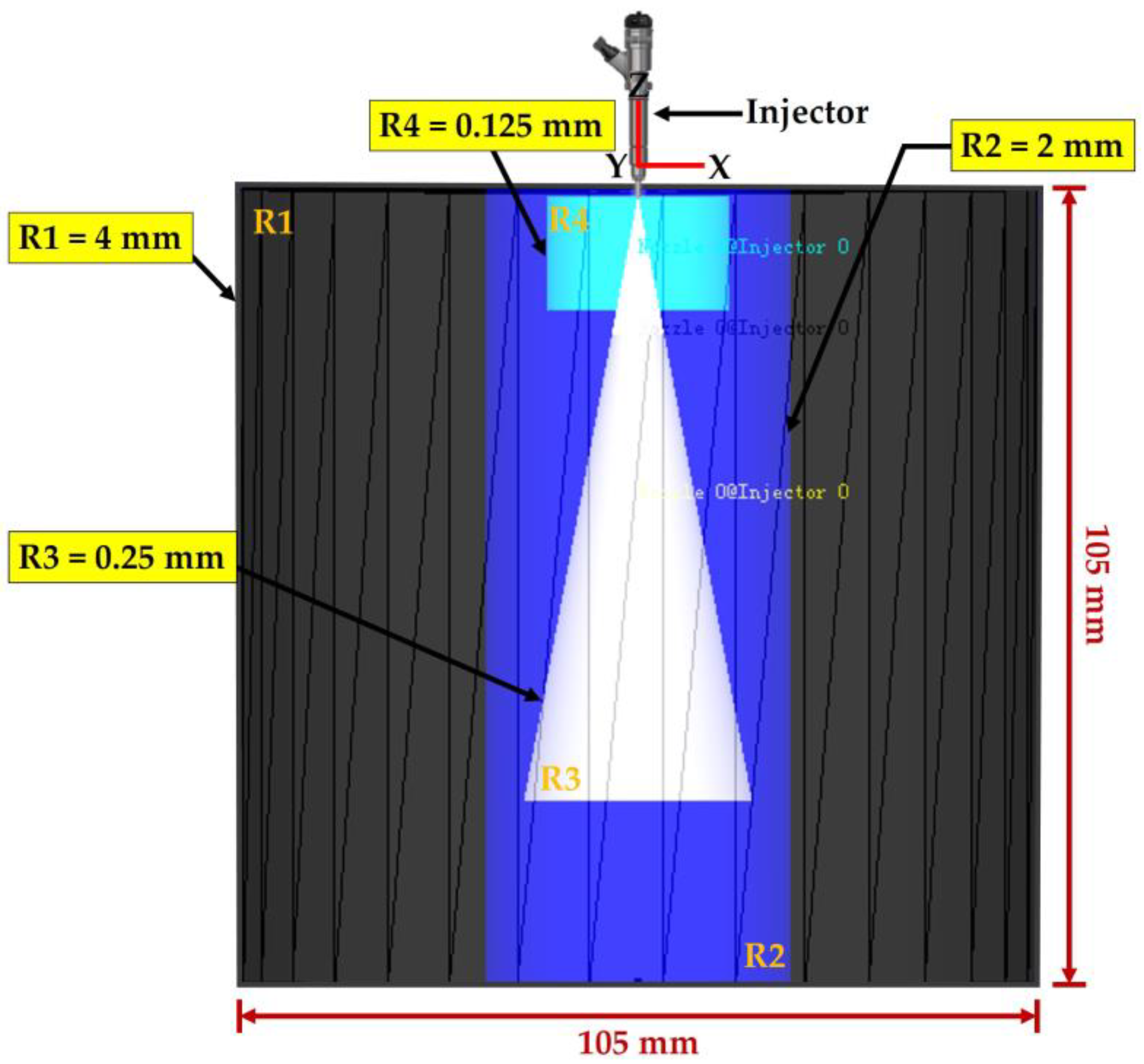
2. Numerical Setup
2.1. Spray Breakup Modeling
2.2. Turbulence Modeling
2.3. Combustion Modeling
3. Results and Discussion
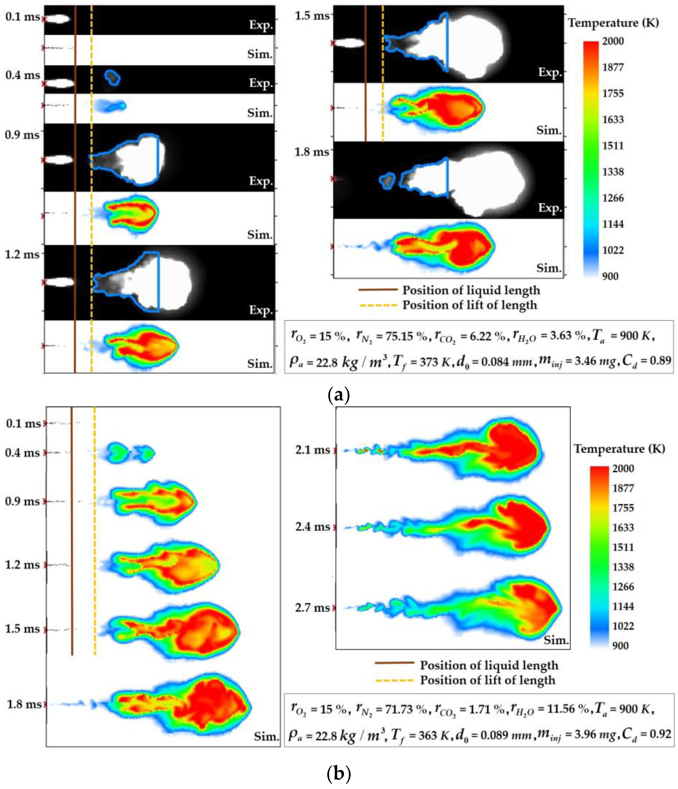
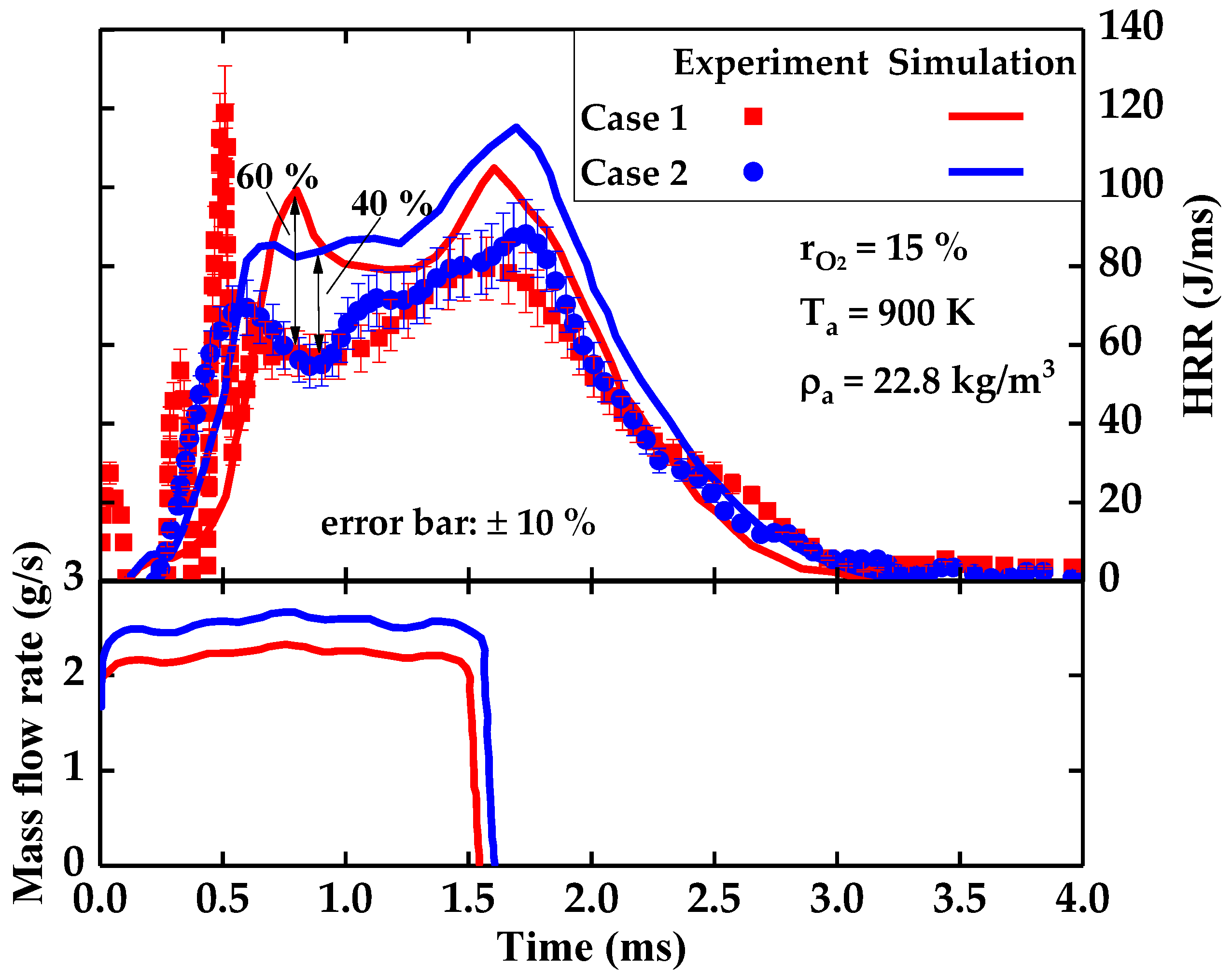
3.1. Model Validation
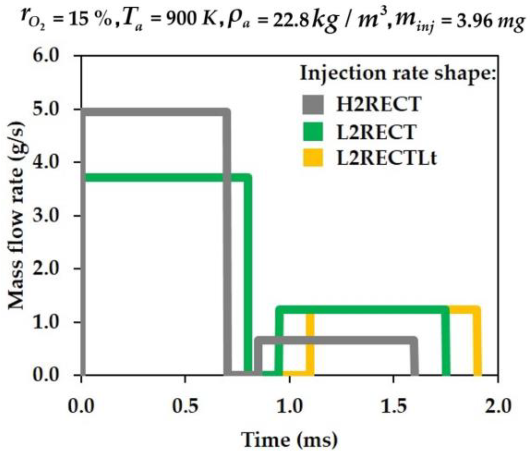
3.2. Impact of Flexible Injection Rates
4. Conclusions
- (1)
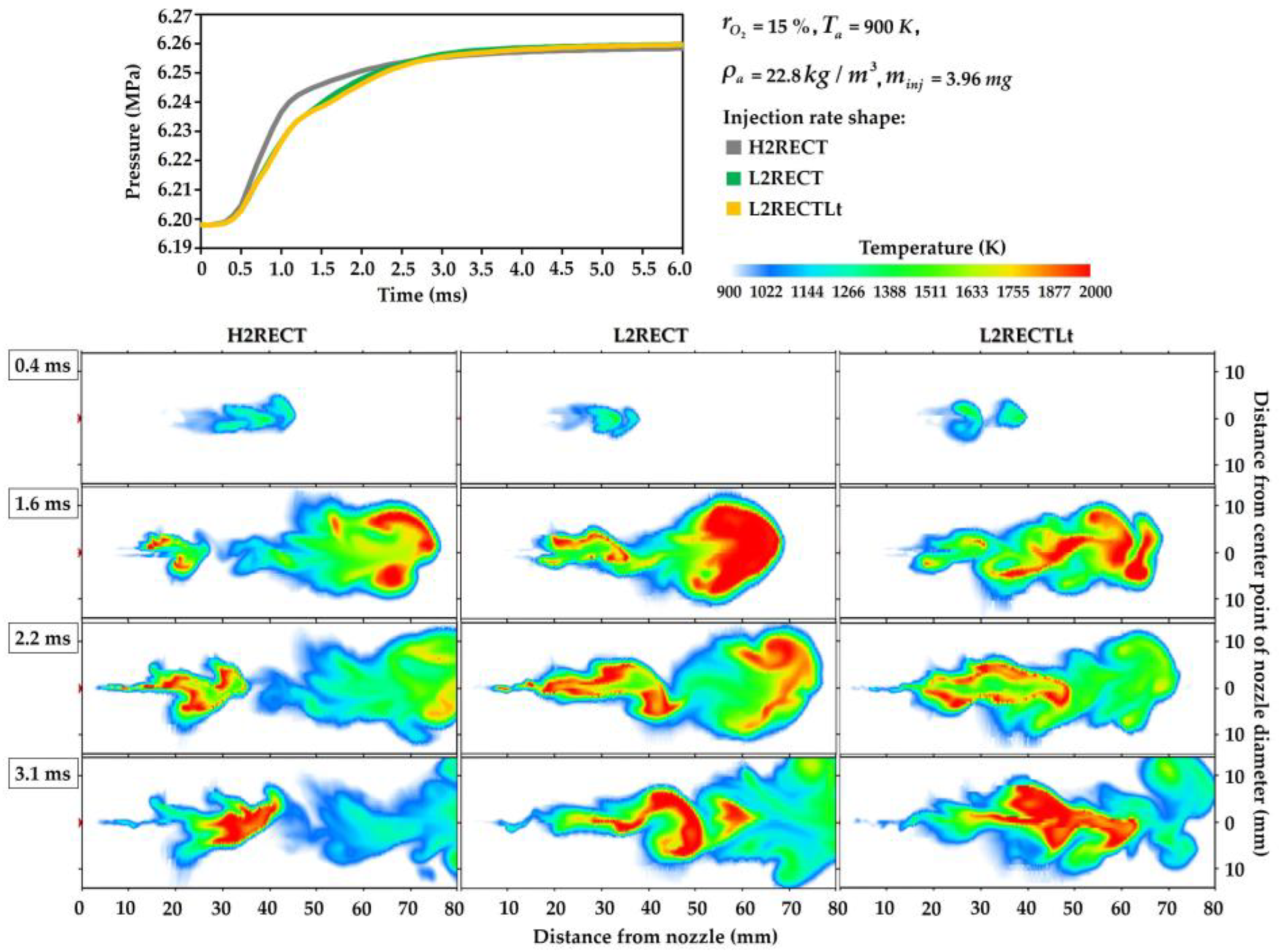
- The initial ultrahigh injection pressure had a significant influence on the spray axial penetration while the dwell time mainly affected the spray radial expansion.
- (2)
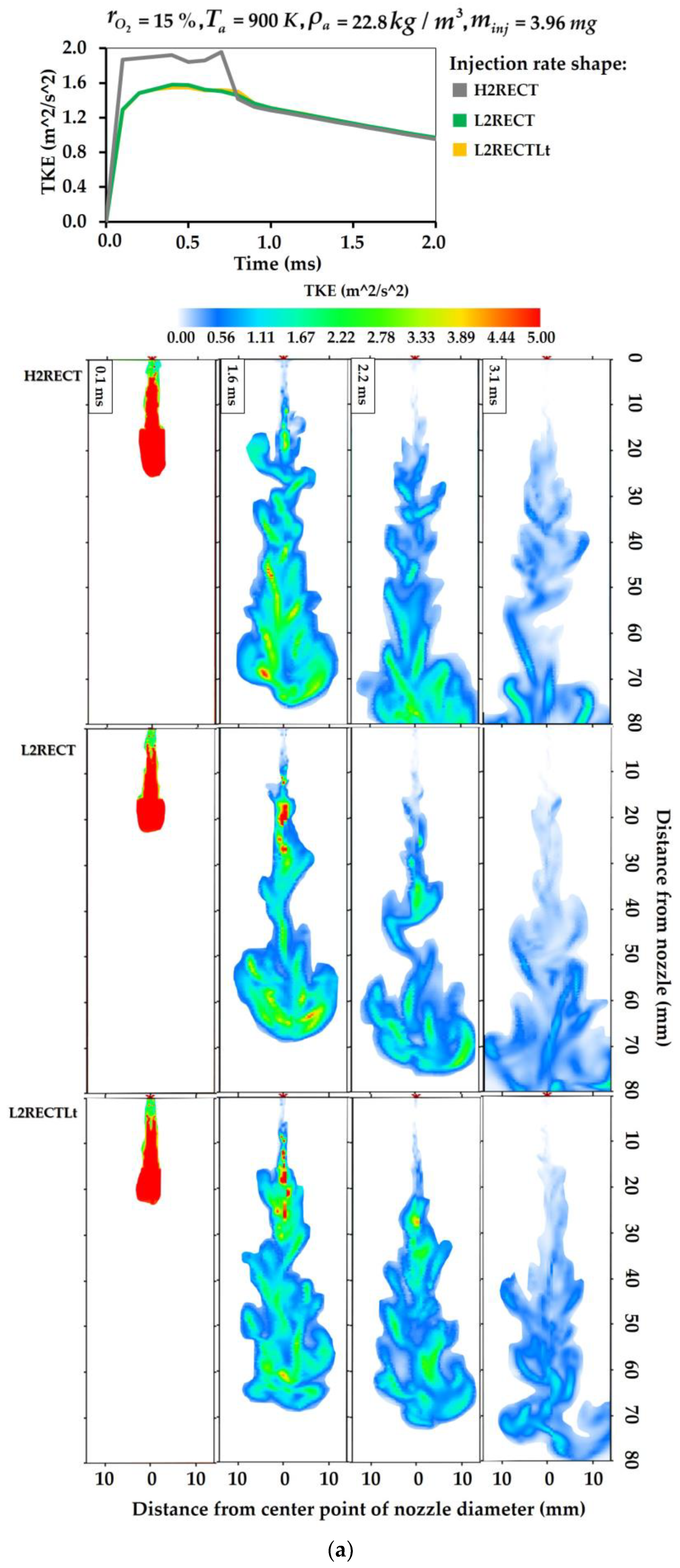
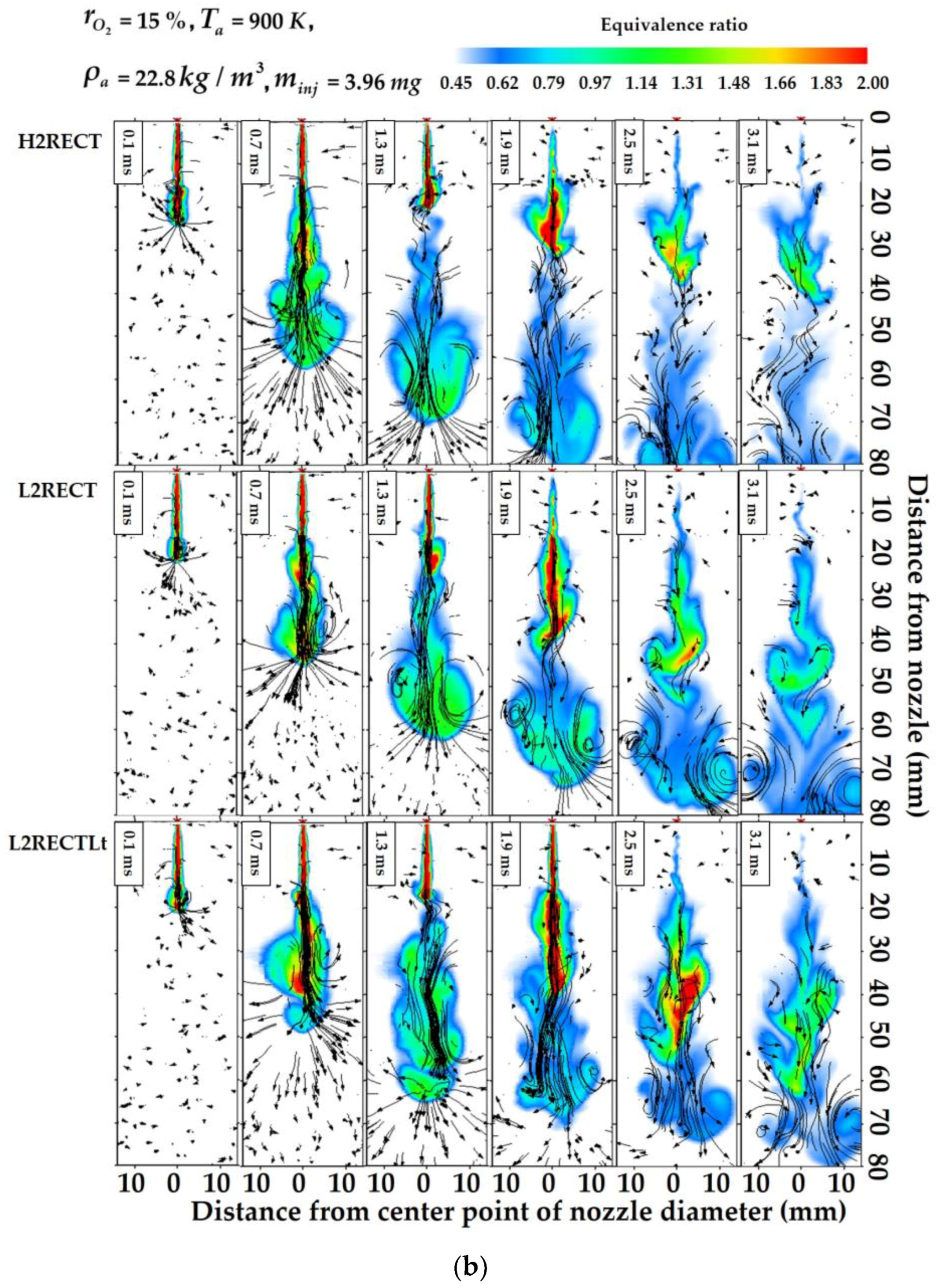
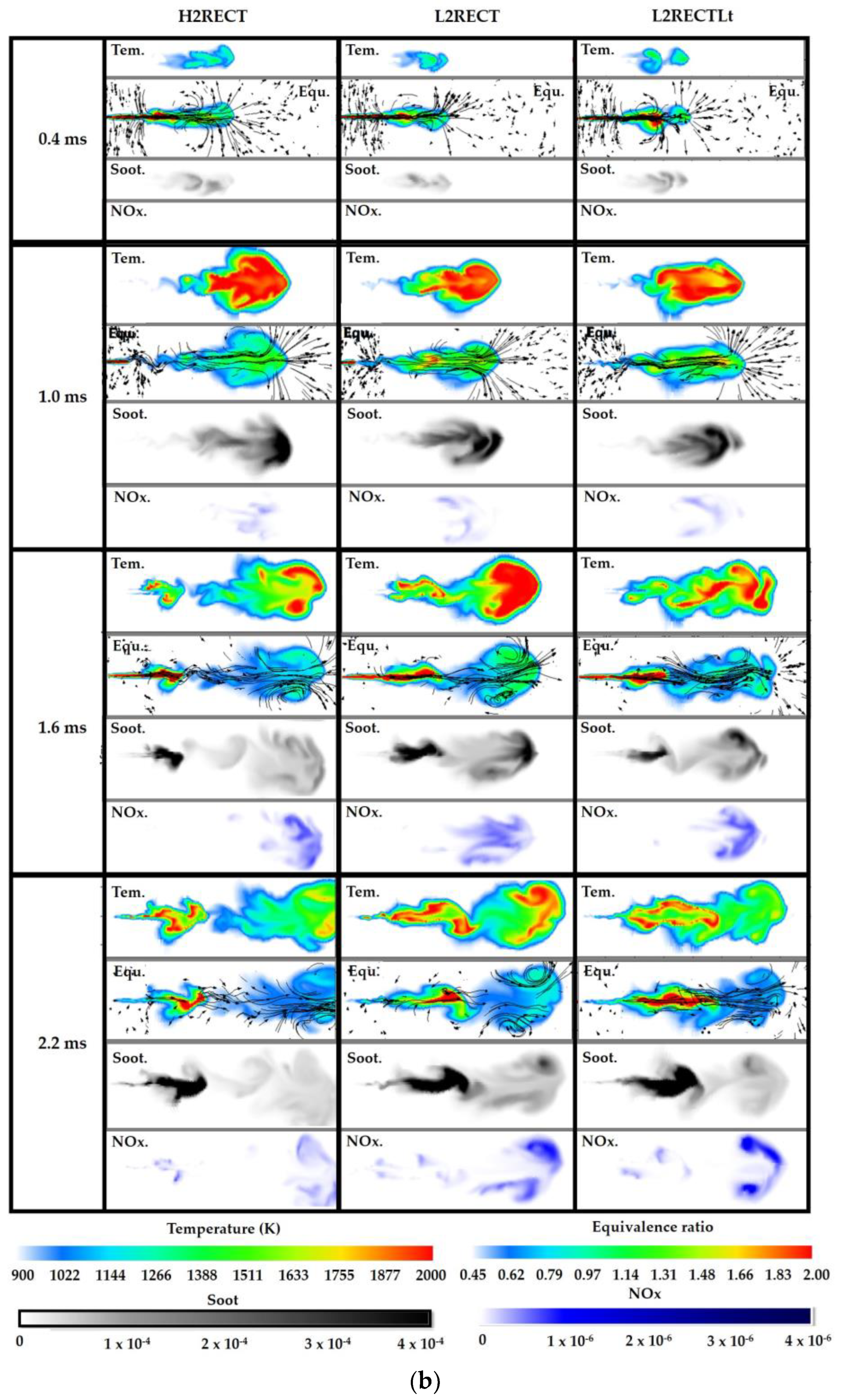
- The H2RECT injection pattern obtained a 20% larger TKE than the L2RECT and the L2RECTLt injection patterns during the first injection due to the initial ultrahigh injection pressure. In the H2RECT injection pattern, the vortex at the spray tip and the downstream flow field were much stronger, contributing to a faster dilute equivalence ratio. There was always a strong flow field going through the whole spray plume in the H2RECT injection pattern, which was beneficial for the material transfer and fuel–air interaction.
- (3)
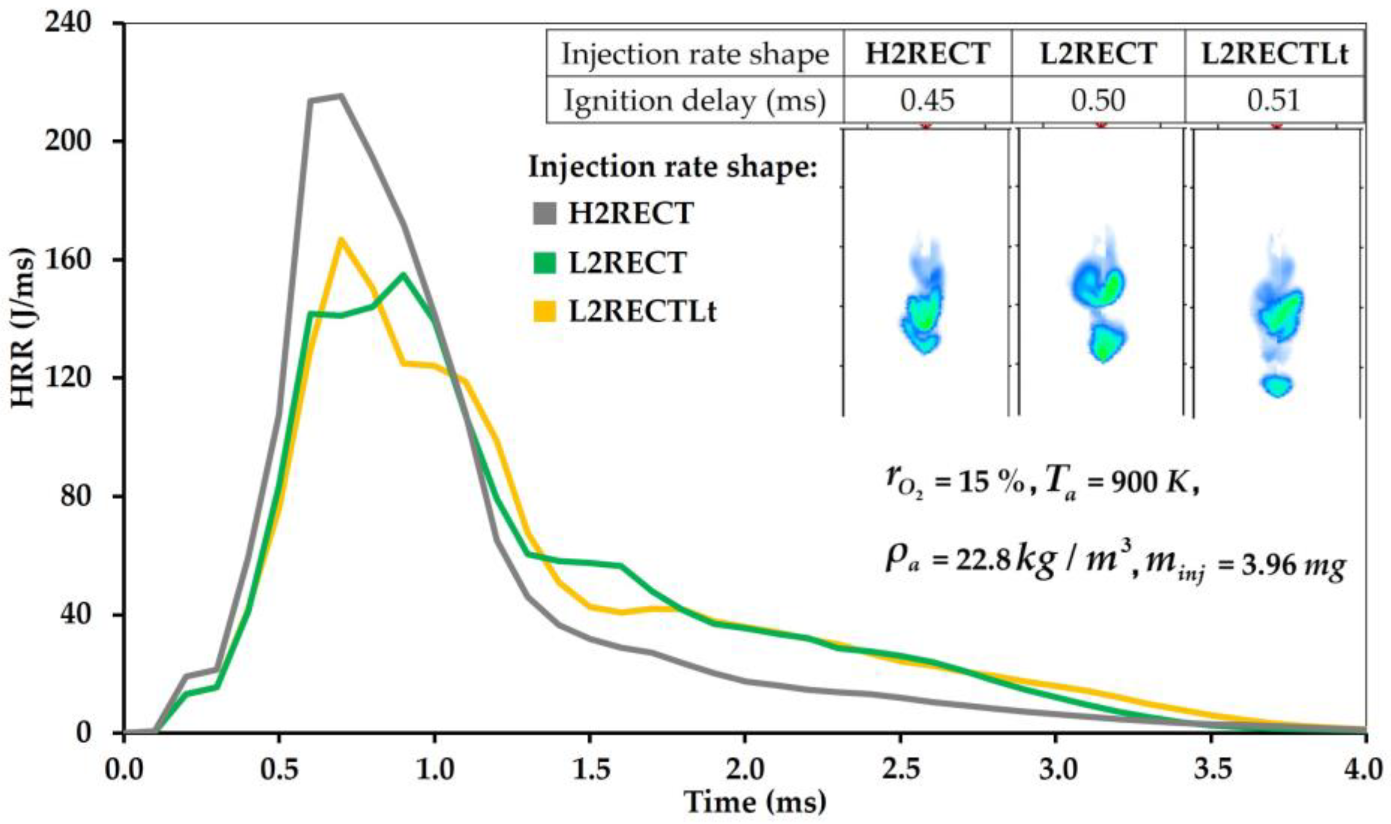
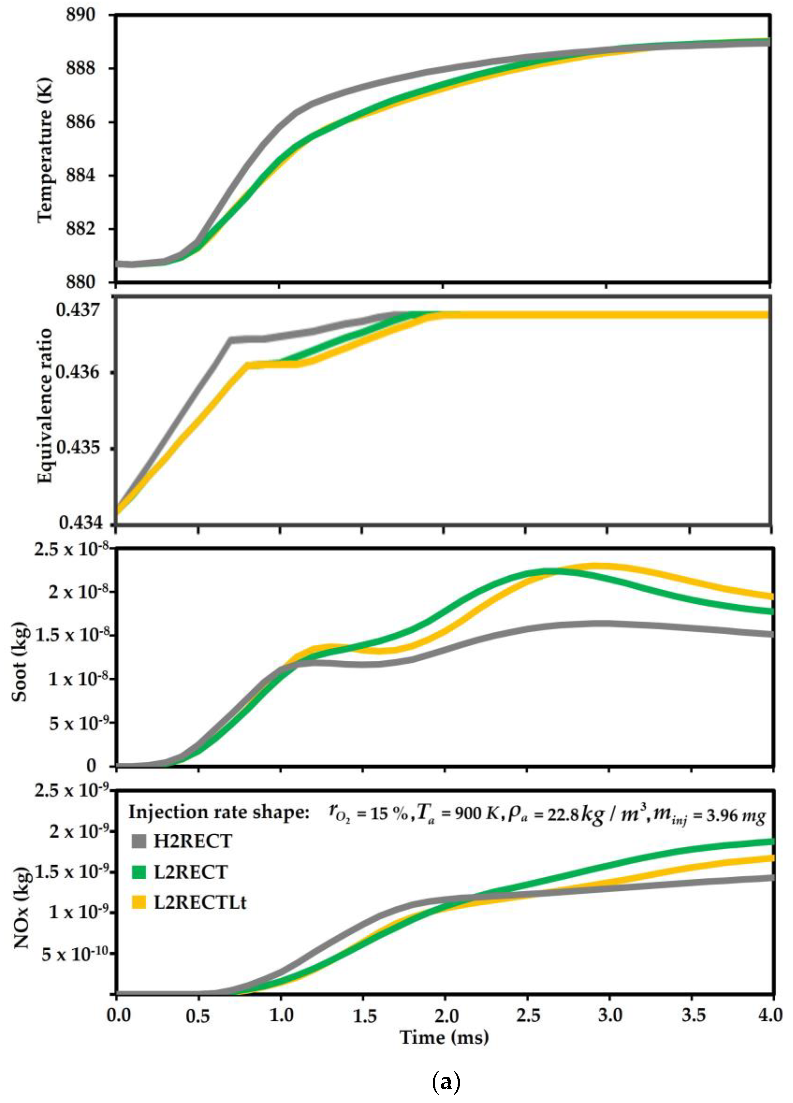
- The H2RECT injection pattern showed an approximately 46.7% higher peak HRR than that of the L2RECT injection pattern because its ultrahigh peak injection pressure brought more combustible fuel in the initial period. The L2RECTLt injection pattern had an approximately 13.3% larger peak HRR than the L2RECT injection pattern due to the better turbulence mixing process from the increased dwell time. However, comparatively, increasing the first injection rate seemed to have a tremendous edge over increasing the dwell time for promoting the combustion efficiency.
- (4)
- The final soot amount of H2RECT was approximately 16.7% and 33.5% lower than that of L2RECT and L2RECTLt, respectively, which was because the late burning of the H2RECT injection pattern was not as strong as that of the L2RECT and L2RECTLt injection patterns due to the lower second injection rate, contributing to a lower formation amount of soot for the H2RECT injection pattern during that stage.
- (5)
- The final NOx amount of H2RECT was approximately 31.4% and 20.0% lower than that of L2RECT and L2RECTLt, respectively. It was because the peak injection pressure of the H2RECT injection pattern greatly improved the spray turbulent mixing process, leading to a homogeneous temperature distribution with a low temperature, which prevented the high-temperature combustion reaction, so the NOx formation was greatly reduced.
Author Contributions
Funding
Institutional Review Board Statement
Informed Consent Statement
Data Availability Statement
Conflicts of Interest
Nomenclature
| 3D | three-dimensional |
| factor of pre-exponential | |
| KH model constant | |
| temperature exponent | |
| CFD | computational fluid dynamics |
| CVCC | constant volume combustion chamber |
| correction factor in RT model | |
| molar constant-pressure specific heat of species | |
| mass diffusivity | |
| ECN | Engine Combustion Network |
| EGR | exhaust gas recirculation |
| activation energy | |
| enthalpy | |
| H2RECT | high 2 rectangular injection rate shape |
| HRR | heat release rate |
| sensible enthalpy | |
| molar specific enthalpy of species | |
| total enthalpy | |
| KH | Kelvin–Helmholtz |
| equilibrium coefficient | |
| equilibrium constant | |
| forward rate coefficient | |
| reverse rate coefficient | |
| L2RECT | low 2 rectangular injection rate shape |
| L2RECTLt | low 2 rectangular injection rate with long dwell time shape |
| LES | large-eddy simulation |
| LTC | low temperature combustion |
| NTC | no time counter |
| pressure | |
| PCCI | premixed charge combustion ignition |
| PISO | Pressure-Implicit with Splitting of Operators |
| atmospheric pressure | |
| radius of the initial droplets | |
| constant of gas | |
| constant of universal gas | |
| entropy | |
| energy source term | |
| momentum source term | |
| species source term | |
| mass source term | |
| RT | Rayleigh–Taylor |
| TKE | turbulence kinetic energy |
| velocity component in direction | |
| URANS | unsteady Reynolds averaged Navier–Stokes |
| chemical species mass fraction | |
| density | |
| viscosity diffusion rate | |
| disruptive growth rate in KH model | |
| growth rate in RT model | |
| wavelength in KH model | |
| wavelength in RT model | |
| KH breakup time | |
| RT breakup time | |
| viscous stress tensor |
References
- Nayak, S.K.; Nižetić, S.; Pham, V.V.; Huang, Z.; Ölçer, A.I.; Bui, V.G.; Wattanavichien, K.; Hoang, A.T. Influence of injection timing on performance and combustion characteristics of compression ignition engine working on quaternary blends of diesel fuel, mixed biodiesel, and t-butyl peroxide. J. Clean. Prod. 2022, 333, 130160. [Google Scholar] [CrossRef]
- Hoang, A.T.; Pham, V.V. A review on fuels used for marine diesel engines. J. Mech. Eng. Res. Dev. (JMERD) 2018, 41, 22–32. [Google Scholar] [CrossRef]
- Bui, V.G.; Tu Bui, T.M.; Hoang, A.T.; Nižetic, S.; Nguyen Thi, T.X.; Vo, A.V. Hydrogen-enriched biogas premixed charge combustion and emissions in direct injection and indirect injection diesel dual fueled engines: A comparative study. J. Energy Resour. Technol.—Trans. ASME 2021, 143, 120907. [Google Scholar] [CrossRef]
- Iqbal, M.; Wang, T.; Li, G.; Li, S.; Hu, G.; Yang, T.; Gu, F.; Al-Nehari, M. Development and Validation of a Vibration-Based Virtual Sensor for Real-Time Monitoring NOx Emissions of a Diesel Engine. Machines 2022, 10, 594. [Google Scholar] [CrossRef]
- Gürbüz, H.; Demirtürk, S.; Akçay, İ.H.; Akçay, H. Effect of port injection of ethanol on engine performance, exhaust emissions and environmental factors in a dual-fuel diesel engine. Energy Environ. 2021, 32, 784–802. [Google Scholar] [CrossRef]
- United States Environmental Protection Agency. Available online: https://www.epa.gov/regulations-emissions-vehicles-and-engines (accessed on 17 March 2022).
- Jo, S.; Cha, J.; Park, S. Exhaust emission characteristics of stoichiometric combustion applying to diesel particulate filter (DPF) and three-way catalytic converter(TWC). Energy 2022, 254, 124196. [Google Scholar] [CrossRef]
- Bobi, S.; Kashif, M.; Laoonual, Y. Combustion and emission control strategies for partially-premixed charge compression ignition engines: A review. Fuel 2022, 310, 122272. [Google Scholar] [CrossRef]
- Batool, S.; Naber, J.D.; Shahbakhti, M. Multi-mode Low Temperature Combustion (LTC) and Mode Switching Control. In Advanced Combustion for Sustainable Transport; Agarwal, A.K., Martínez, A.G., Kalwar, A., Valera, H., Eds.; Energy, Environment, and Sustainability; Springer: Singapore, 2022; pp. 43–93. ISBN 9789811684173. [Google Scholar]
- Chen, D.; Wang, T.; Yang, T.; Li, G.; Chen, Y.; Qiao, T. Effects of EGR combined with DOC on emission characteristics of a two-stage injected Fischer-Tropsch diesel/methanol dual-fuel engine. Fuel 2022, 329, 125451. [Google Scholar] [CrossRef]
- Payri, R.; Gimeno, J.; Viera, J.P.; Plazas, A.H. Needle lift profile influence on the vapor phase penetration for a prototype diesel direct acting piezoelectric injector. Fuel 2013, 113, 257–265. [Google Scholar] [CrossRef] [Green Version]
- Macian, V.; Payri, R.; Ruiz, S.; Bardi, M.; Plazas, A.H. Experimental study of the relationship between injection rate shape and Diesel ignition using a novel piezo-actuated direct-acting injector. Appl. Energy 2014, 118, 100–113. [Google Scholar] [CrossRef]
- Aalam, C.S.; Saravanan, C.G.; Anand, B.P. Impact of high fuel injection pressure on the characteristics of CRDI diesel engine powered by mahua methyl ester blend. Appl. Therm. Eng. 2016, 106, 702–711. [Google Scholar] [CrossRef]
- Nishida, K.; Zhu, J.; Leng, X.; He, Z. Effects of micro-hole nozzle and ultra-high injection pressure on air entrainment, liquid penetration, flame lift-off and soot formation of diesel spray flame. Int. J. Engine Res. 2017, 18, 51–65. [Google Scholar] [CrossRef]
- Vera-Tudela, W.; Haefeli, R.; Barro, C.; Schneider, B.; Boulouchos, K. An experimental study of a very high-pressure diesel injector (up to 5000 bar) by means of optical diagnostics. Fuel 2020, 275, 117933. [Google Scholar] [CrossRef]
- Naruemon, I.; Liu, L.; Mei, Q.; Ma, X. Investigation on an injection strategy optimization for diesel engines using a one-dimensional spray model. Energies 2019, 12, 4221. [Google Scholar] [CrossRef] [Green Version]
- Naruemon, I.; Liu, L.; Liu, D.; Ma, X.; Nishida, K. An analysis on the effects of the fuel injection rate shape of the diesel spray mixing process using a numerical simulation. Appl. Sci. 2020, 10, 4983. [Google Scholar] [CrossRef]
- Boggavarapu, P.; Singh, S. Computational Study of Injection Rate-Shaping for Emissions Control in Diesel Engines; SAE Technical Paper 2011-26-0081; SAE International: Warrendale, PA, USA, 2011. [Google Scholar] [CrossRef]
- Ramirez, A.I.; Som, S.; Rutter, T.P.; Longman, D.E.; Aggarwal, S.K. Investigation of the Effects of Rate of Injection on Combustion Phasing and Emission Characteristics: Experimental and Numerical Study. In Proceedings of the Central States Section of the Combustion Institute Spring Technical Meeting, Dayton, OH, USA, 23–24 April 2012. [Google Scholar]
- Mohan, B.; Yang, W.; Yu, W.; Tay, K.L.; Chou, S.K. Numerical investigation on the effects of injection rate shaping on combustion and emission characteristics of biodiesel fueled CI engine. Appl. Energy 2015, 160, 737–745. [Google Scholar] [CrossRef]
- Tay, K.L.; Yang, W.; Zhao, F.; Yu, W.; Mohan, B. Effects of triangular and ramp injection rate-shapes on the performance and emissions of a kerosene-diesel fueled direct injection compression ignition engine: A numerical study. Appl. Therm. Eng. 2017, 110, 1401–1410. [Google Scholar] [CrossRef]
- Skeen, S.; Manin, J.; Pickett, L.M. Visualization of Ignition Processes in High-Pressure Sprays with Multiple Injections of n-Dodecane. SAE Int. J. Engines 2015, 8, 696–715. [Google Scholar] [CrossRef]
- Bolla, M.; Chishty, M.A.; Hawkes, E.R.; Kook, S. Modeling combustion under engine combustion network Spray A conditions with multiple injections using the transported probability density function method. Int. J. Engine Res. 2017, 18, 6–14. [Google Scholar] [CrossRef]
- Cung, K.; Moiz, A.; Johnson, J.; Lee, S.Y.; Kweon, C.B.; Montanaro, A. Spray-combustion interaction mechanism of multiple-injection under diesel engine conditions. Proc. Combust. Inst. 2015, 35, 3061–3068. [Google Scholar] [CrossRef] [Green Version]
- Moiz, A.A.; Ameen, M.M.; Lee, S.Y.; Som, S. Study of soot production for double injections of n-dodecane in CI engine-like conditions. Combust. Flame 2016, 173, 123–131. [Google Scholar] [CrossRef] [Green Version]
- Zheng, Z.; Yue, L.; Liu, H.; Zhu, Y.; Zhong, X.; Yao, M. Effect of two-stage injection on combustion and emissions under high EGR rate on a diesel engine by fueling blends of diesel/gasoline, diesel/n-butanol, diesel/gasoline/n-butanol and pure diesel. Energy Convers. Manag. 2015, 90, 1–11. [Google Scholar] [CrossRef]
- Naruemon, I.; Liu, L.; Mei, Q.; Wu, Y.; Ma, X.; Nishida, K. Investigating the effect of split injection with different injection patterns on diesel spray mixing. Front. Energy Res. 2022, 10, 933591. [Google Scholar] [CrossRef]
- Rostampour, A.; Shojaeefard, M.H.; Molaeimanesh, G.R. A comprehensive investigation of RANS and LES turbulence models for diesel spray modeling via experimental diesel schlieren imaging. Proc. Inst. Mech. Eng. Part C J. Mech. Eng. Sci. 2022, 236, 8321–8337. [Google Scholar] [CrossRef]
- Nemati, A.; Ong, J.C.; Walther, J.H. CFD analysis of combustion and emission formation using URANS and LES under large two-stroke marine engine-like conditions. Appl. Therm. Eng. 2022, 216, 119037. [Google Scholar] [CrossRef]
- Salehi, F.; Ghiji, M.; Chen, L. Large eddy simulation of high pressure spray with the focus on injection pressure. Int. J. Heat Fluid Flow 2020, 82, 108551. [Google Scholar] [CrossRef]
- Wen, X.; Gierth, S.; Rieth, M.; Chen, J.H.; Hasse, C. Large-eddy simulation of a multi-injection flame in a diesel engine environment using an unsteady flamelet/progress variable approach. Phys. Fluids 2021, 33, 105107. [Google Scholar] [CrossRef]
- Senecal, P.K.; Pomraning, E.; Richards, K.J.; Briggs, T.E.; Choi, C.Y.; McDavid, R.M.; Patterson, M.A. Multi-Dimensional Modeling of Direct-Injection Diesel Spray Liquid Length and Flame Lift-Off Length Using CFD and Parallel Detailed Chemistry; SAE Technical Paper 2003-01-1043; SAE International: Warrendale, PA, USA, 2003. [Google Scholar] [CrossRef]
- Sun, X.; Liang, X.; Shu, G.; Wang, Y.; Wang, Y.; Yu, H. Effect of different combustion models and alternative fuels on two-stroke marine diesel engine performance. Appl. Therm. Eng. 2017, 115, 597–606. [Google Scholar] [CrossRef]
- Gong, C.; Jangi, M.; Bai, X.S. Large eddy simulation of n-Dodecane spray combustion in a high pressure combustion vessel. Appl. Energy 2014, 136, 373–381. [Google Scholar] [CrossRef]
- Engine Combustion Network. Available online: http://www.sandia.gov/ecn (accessed on 17 March 2022).
- Som, S.; Aggarwal, S.K. Effects of primary breakup modeling on spray and combustion characteristics of compression ignition engines. Combust. Flame 2010, 157, 1179–1193. [Google Scholar] [CrossRef]
- Mehl, M.; Pitz, W.J.; Westbrook, C.K.; Curran, H.J. Kinetic modeling of gasoline surrogate components and mixtures under engine conditions. Proc. Combust. Inst. 2011, 33, 193–200. [Google Scholar] [CrossRef]


| Modeling Tool | Converge |
|---|---|
| Spray models | |
| Drop evaporation model | Frossling model |
| Collision model | NTC collision |
| Collision outcome | O’Rourke collision outcomes |
| Drop drag model | Dynamic drop drag |
| Breakup | KH-RT model |
| Turbulence model | LES, Dynamic Structure |
| Combustion model | SAGE |
| Parameters | Case 1 | Case 2 |
|---|---|---|
| Fuel | n-dodecane | n-dodecane |
| Nominal nozzle diameter (μm) | 84 | 89 |
| Injection pressure (MPa) | 150 | 150 |
| Injection duration (ms) | 1.54 | 1.60 |
| Ambient temperature (K) | 900 | 900 |
| Ambient density (kg/m3) | 22.8 | 22.8 |
| Molar concentration of O2 (%) | 15 | 15 |
| Injection Rate Shape | 1st Injection Duration (ms) | Dwell (ms) | 2nd Injection Duration (ms) |
|---|---|---|---|
| H2RECT | 0.70 | 0.15 | 0.75 |
| L2RECT | 0.80 | 0.15 | 0.80 |
| L2RECTLt | 0.80 | 0.30 | 0.80 |
Disclaimer/Publisher’s Note: The statements, opinions and data contained in all publications are solely those of the individual author(s) and contributor(s) and not of MDPI and/or the editor(s). MDPI and/or the editor(s) disclaim responsibility for any injury to people or property resulting from any ideas, methods, instructions or products referred to in the content. |
© 2023 by the authors. Licensee MDPI, Basel, Switzerland. This article is an open access article distributed under the terms and conditions of the Creative Commons Attribution (CC BY) license (https://creativecommons.org/licenses/by/4.0/).
Share and Cite
Mei, Q.; Naruemon, I.; Liu, L.; Wu, Y.; Ma, X. Numerical Investigation on the Combustion and Emission Characteristics of Diesel Engine with Flexible Fuel Injection. Machines 2023, 11, 120. https://doi.org/10.3390/machines11010120
Mei Q, Naruemon I, Liu L, Wu Y, Ma X. Numerical Investigation on the Combustion and Emission Characteristics of Diesel Engine with Flexible Fuel Injection. Machines. 2023; 11(1):120. https://doi.org/10.3390/machines11010120
Chicago/Turabian StyleMei, Qihao, Intarat Naruemon, Long Liu, Yue Wu, and Xiuzhen Ma. 2023. "Numerical Investigation on the Combustion and Emission Characteristics of Diesel Engine with Flexible Fuel Injection" Machines 11, no. 1: 120. https://doi.org/10.3390/machines11010120