
The Neutral Voltage Difference Signal as a Means of Investigating Eccentricity and Demagnetization Faults in an AFPM Synchronous Generator

Abstract
:1. Introduction
2. Materials and Methods
2.1. The AFPM Synchronous Generator
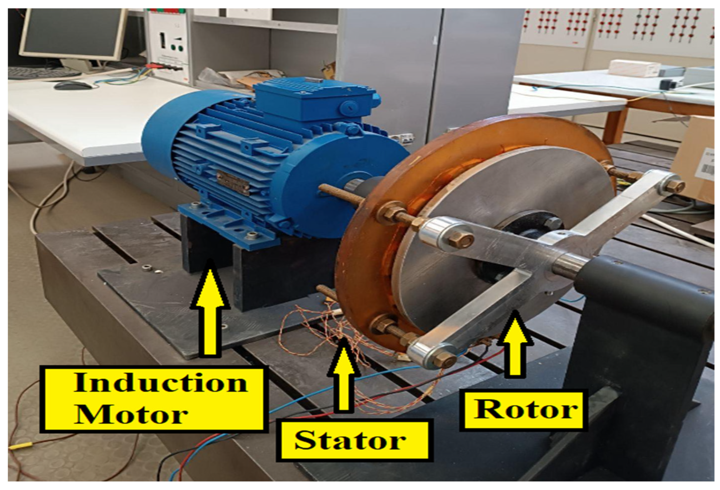
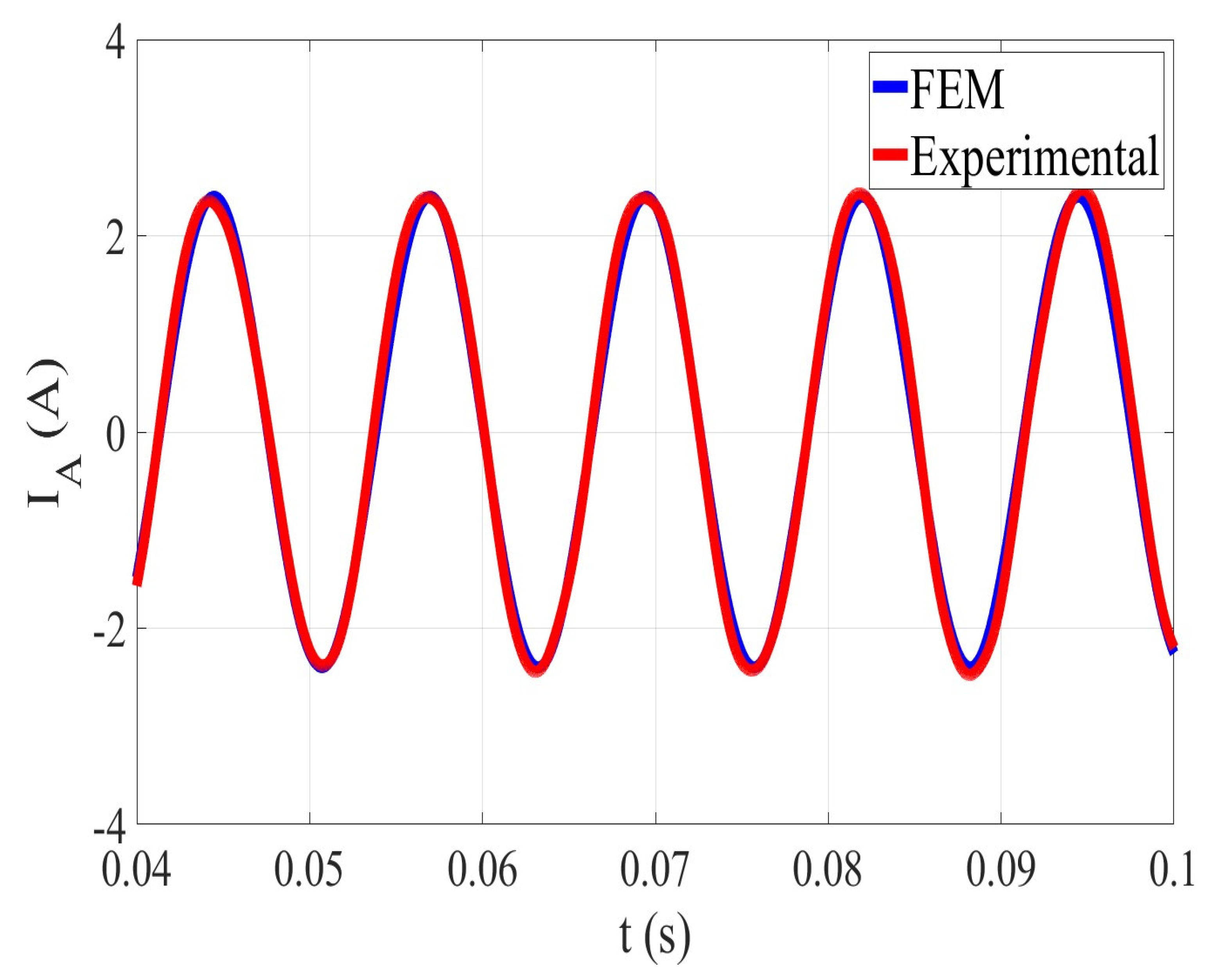
2.2. Experimental Validation of the Generator Model
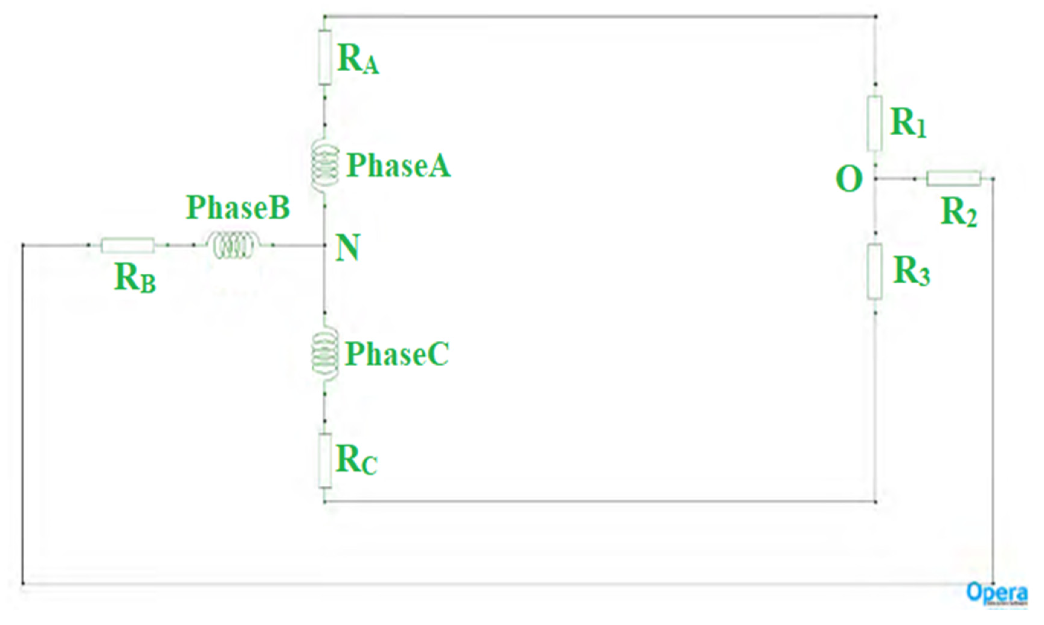
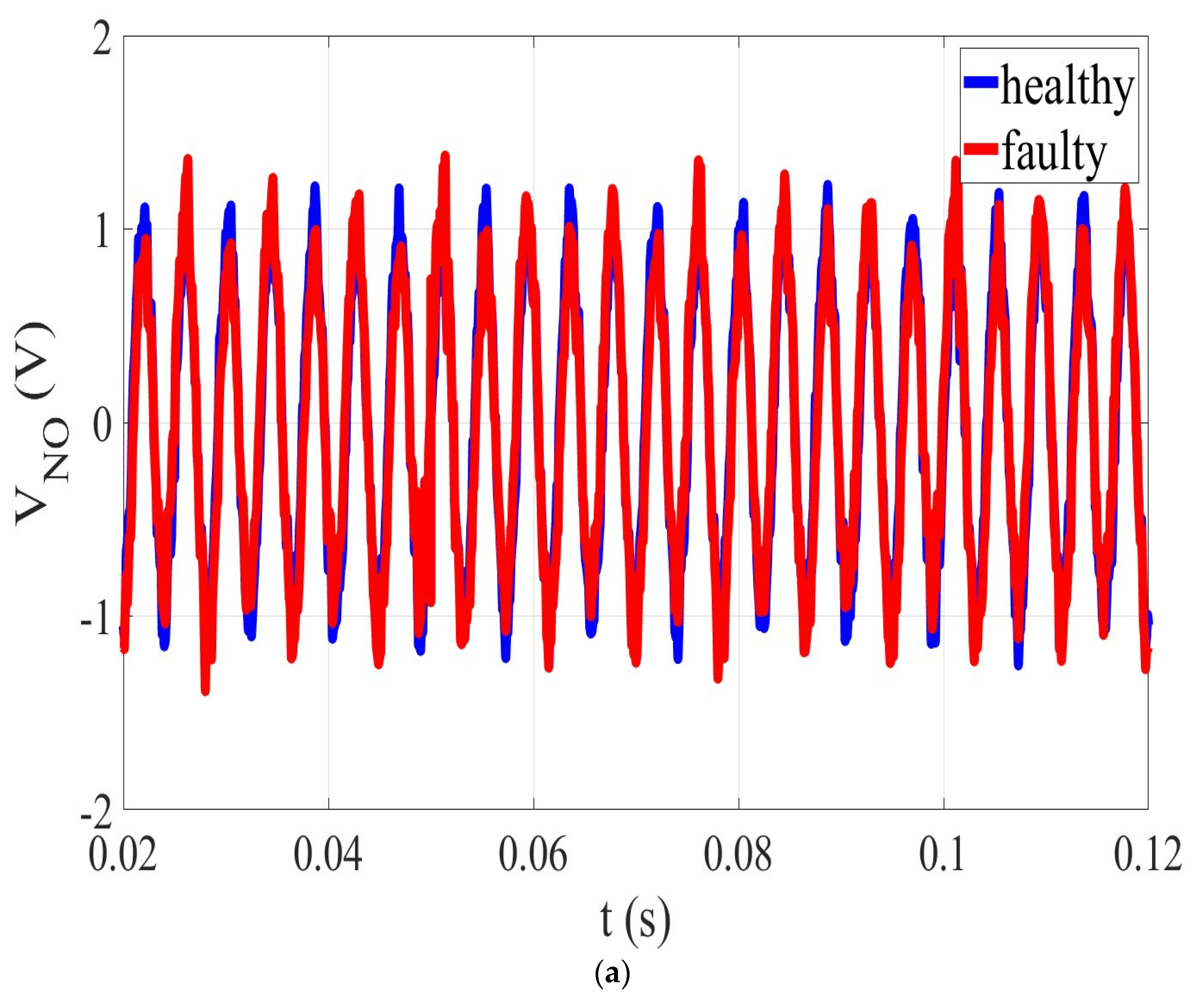
2.3. The Proposed Method
3. Results
3.1. Demagnetization Fault
3.2. Eccentricity Fault
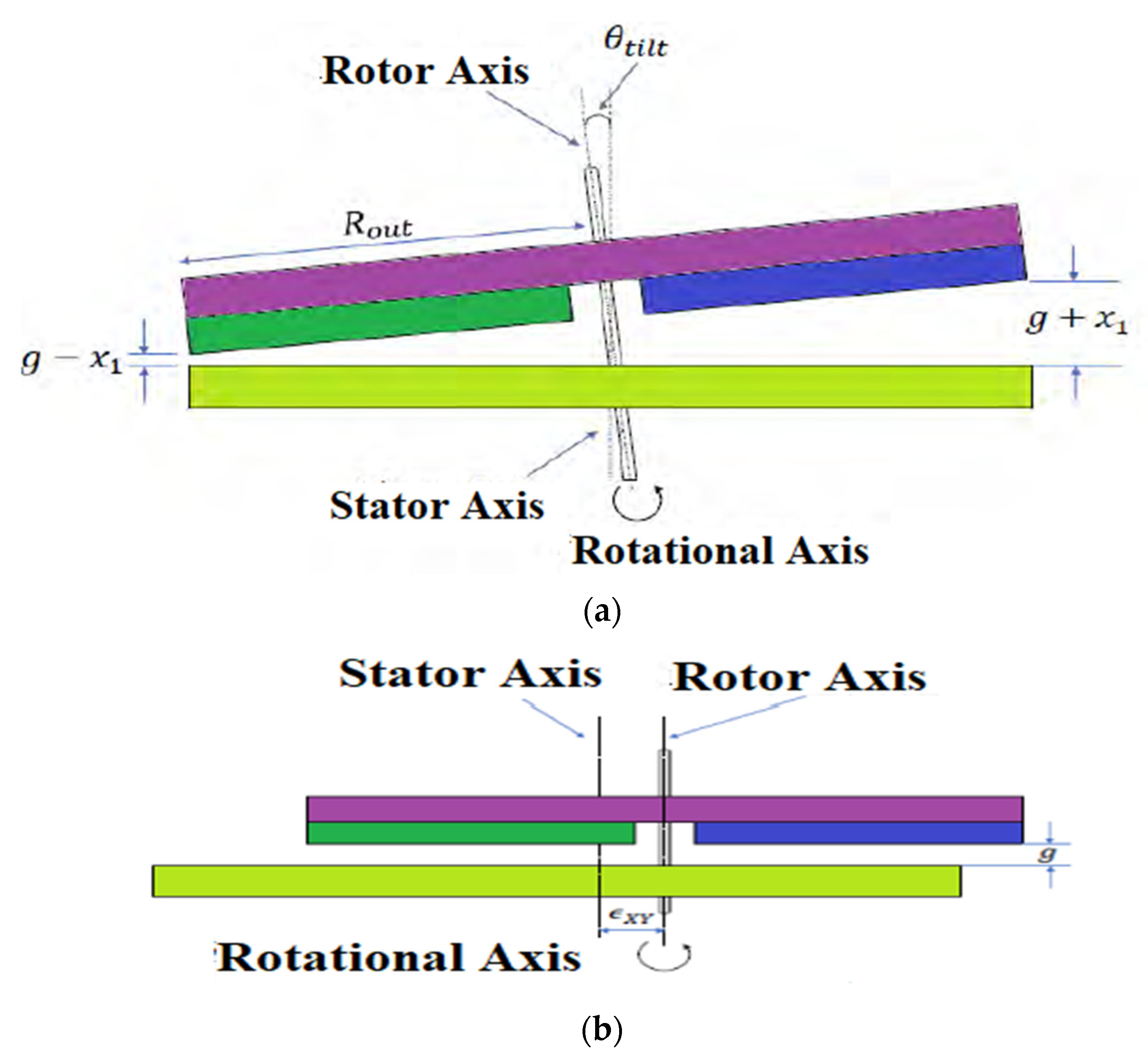
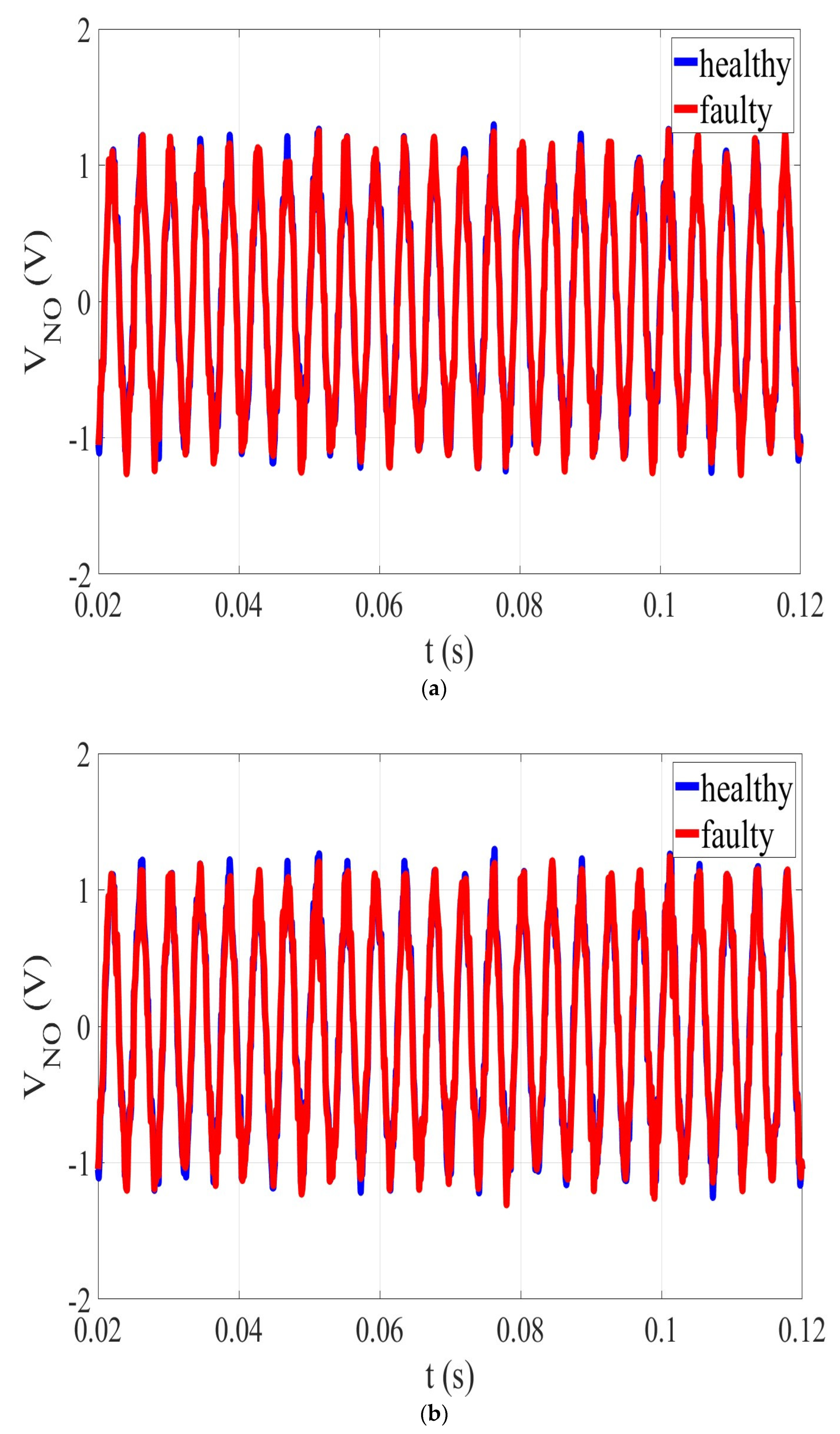
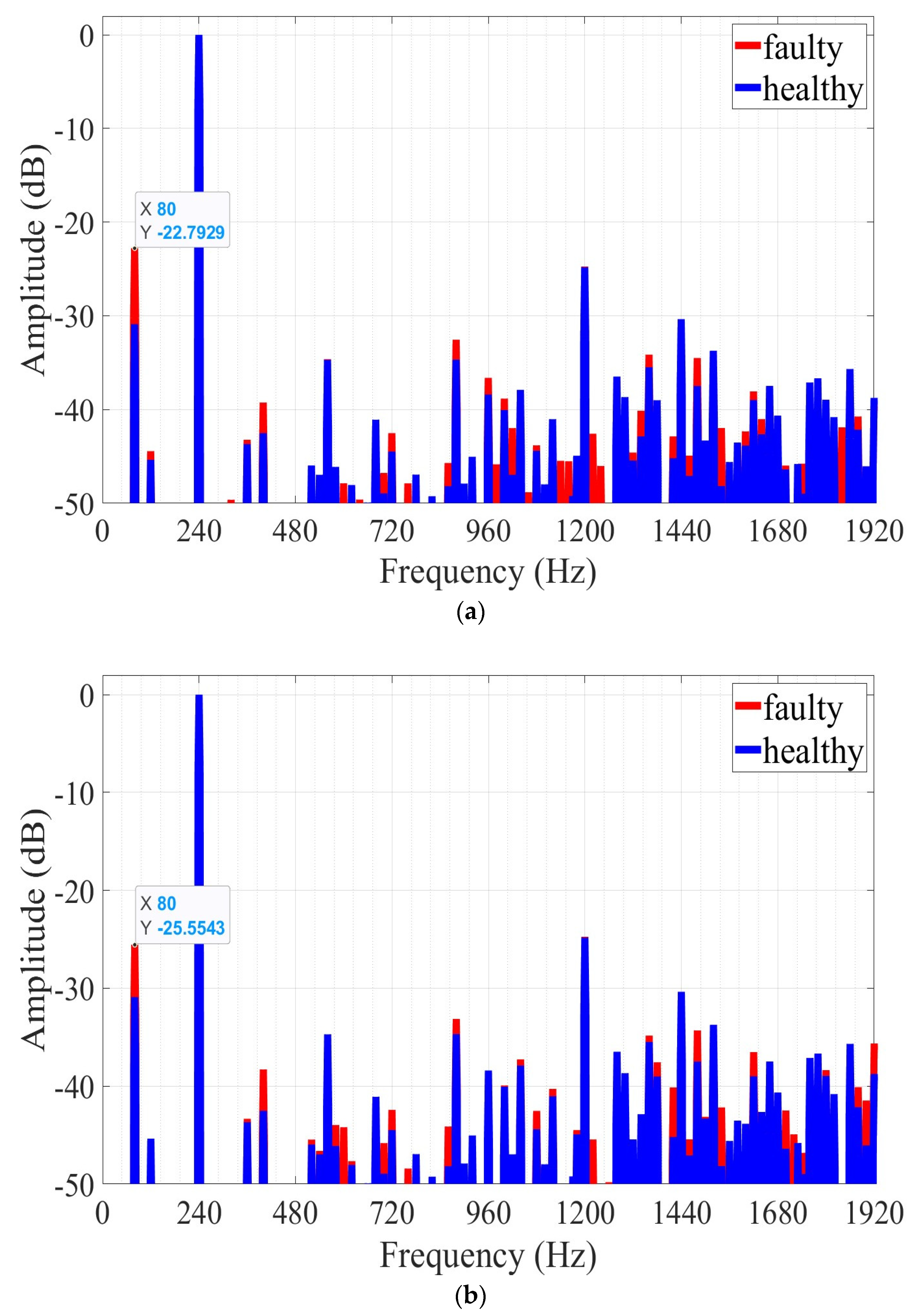
3.2.1. Angular Eccentricity Fault
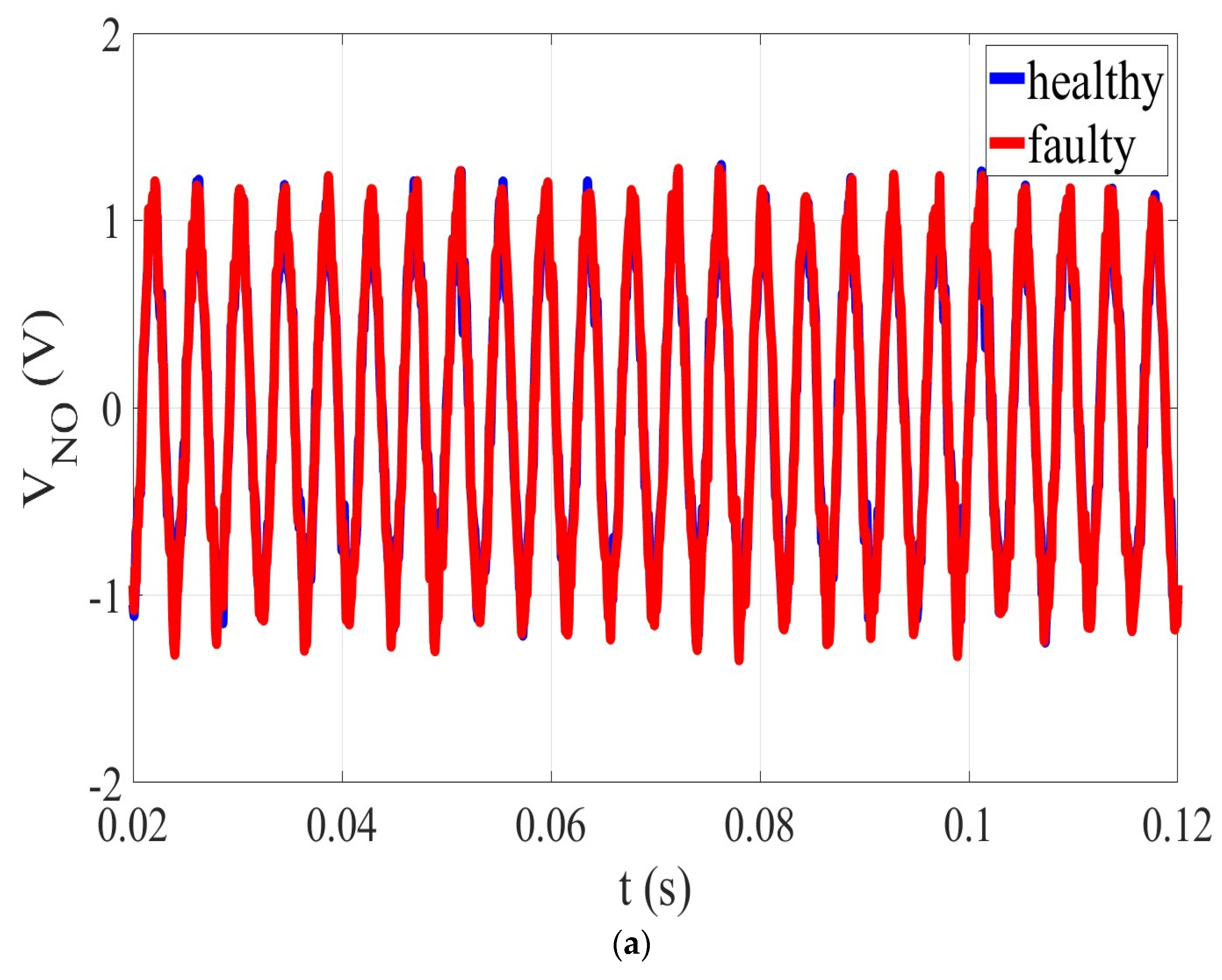
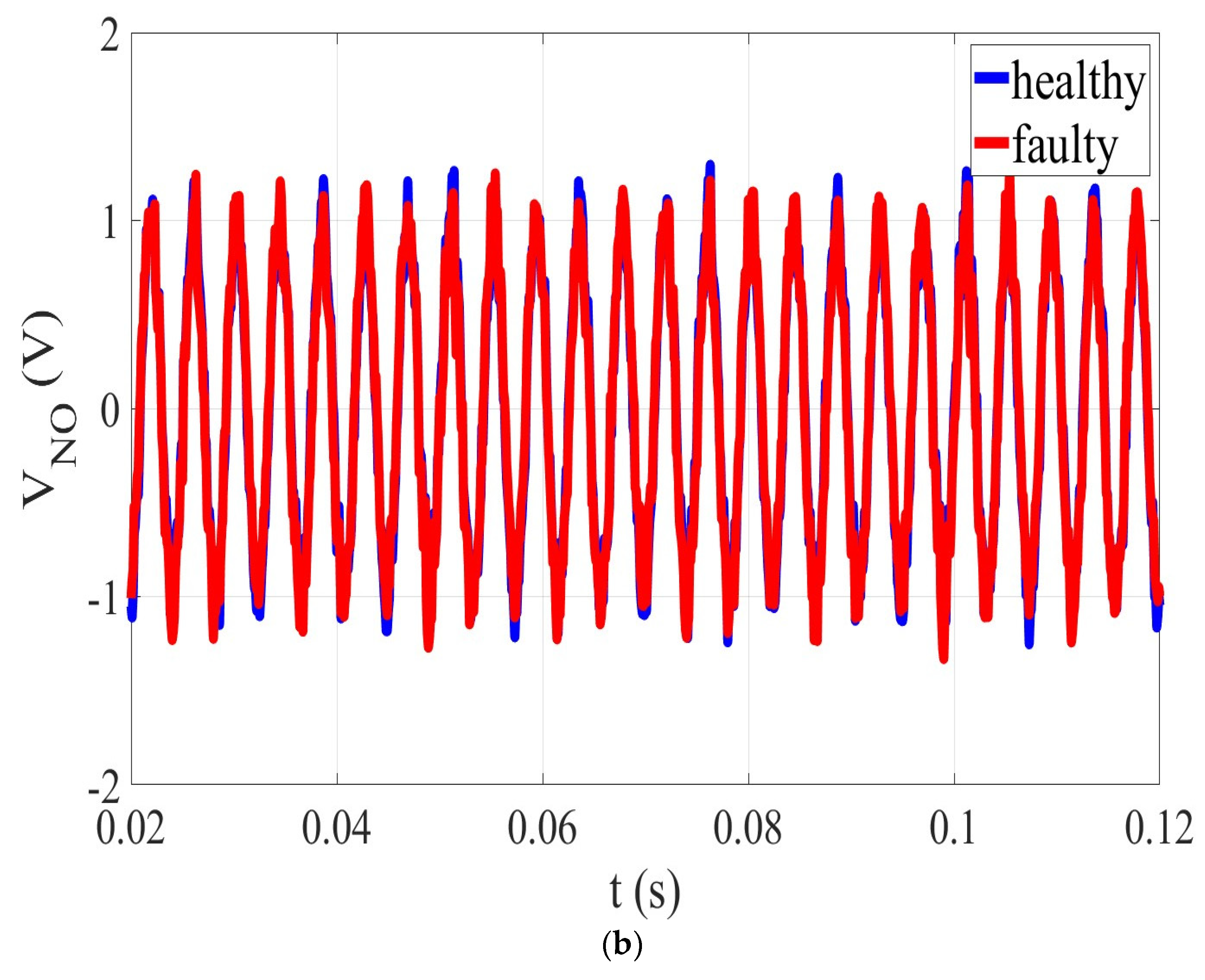
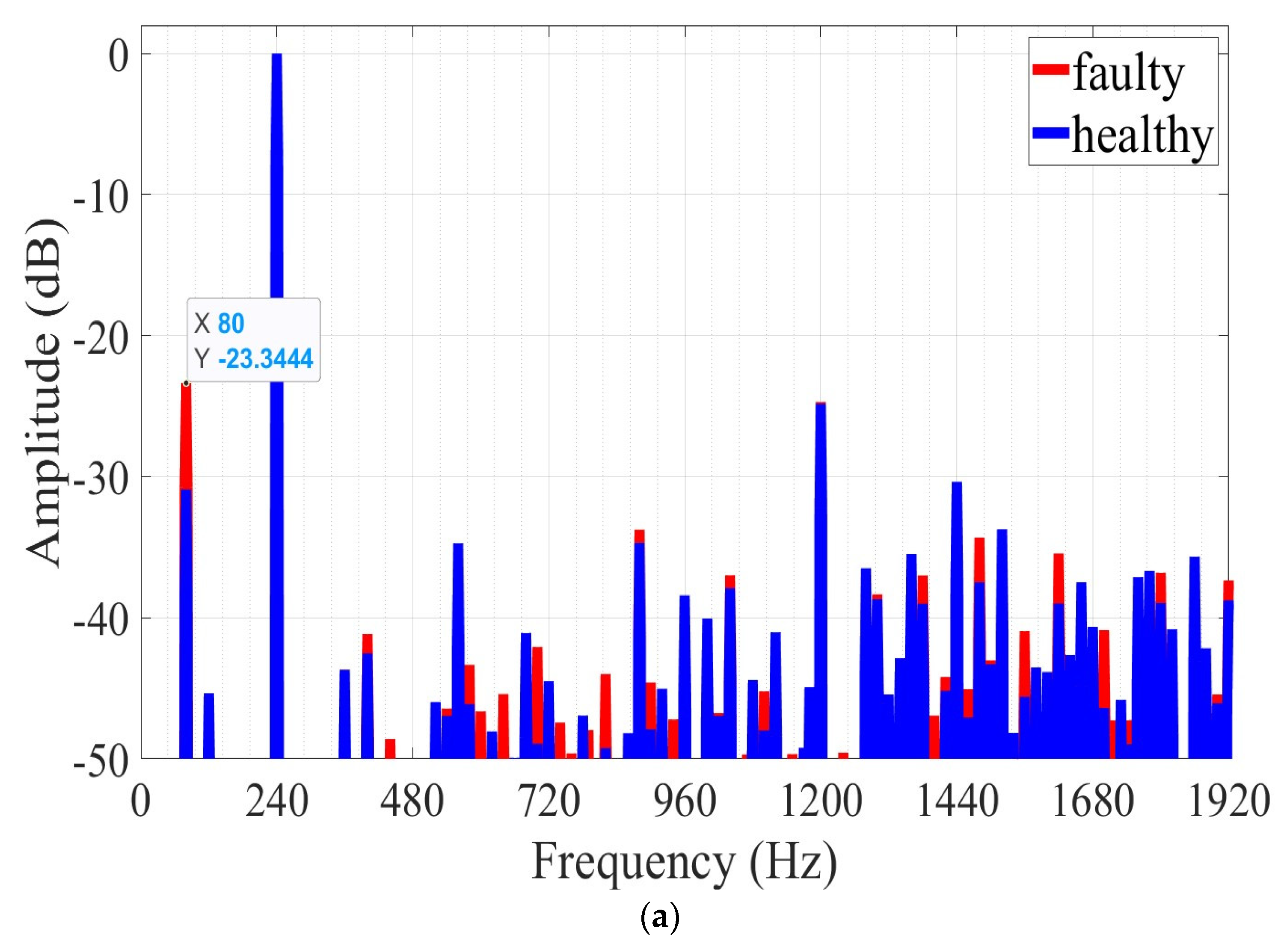
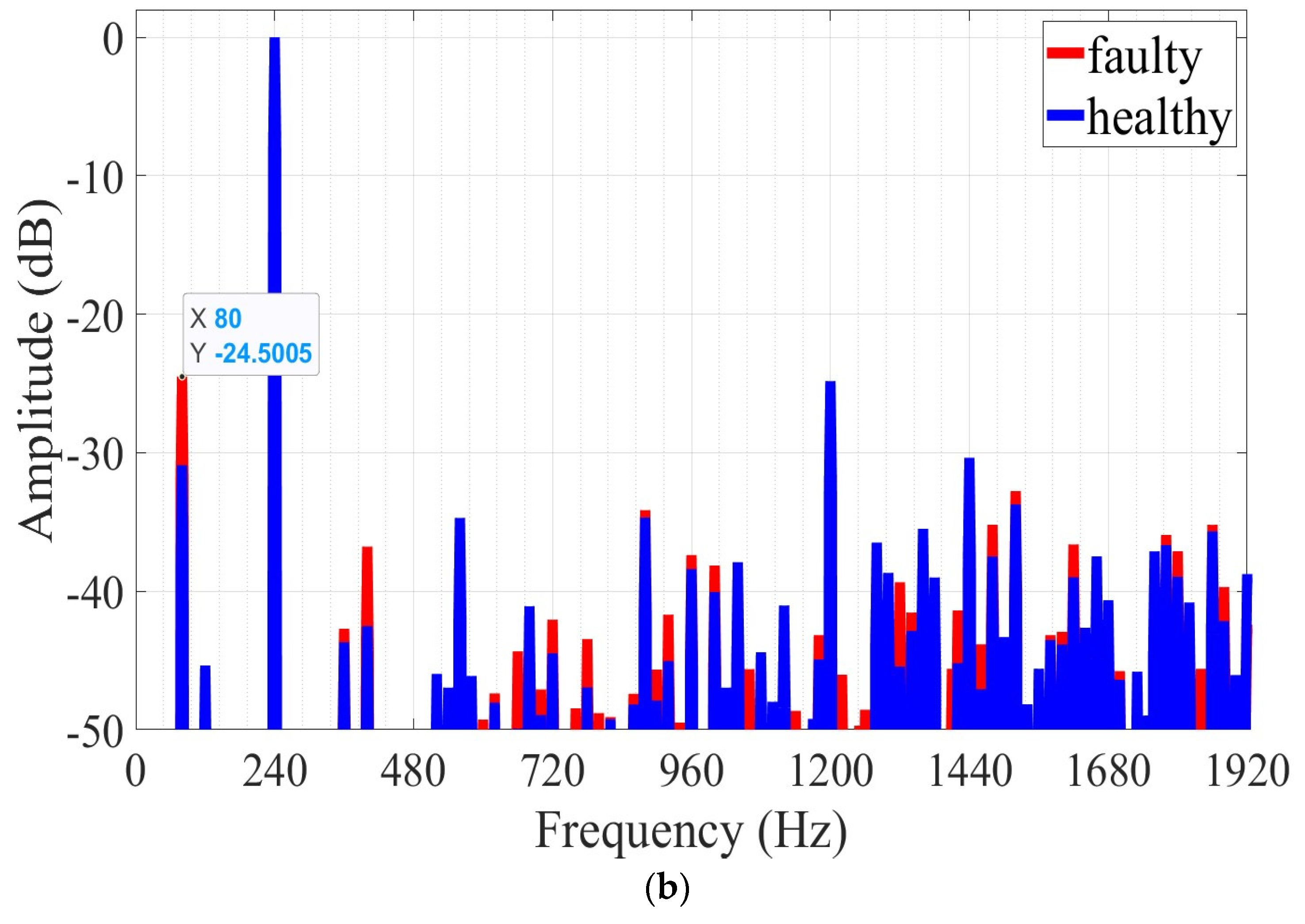
3.2.2. Axial Eccentricity Fault
4. Discussion
Funding
Acknowledgments
Conflicts of Interest
References
- Hyun, D.; Lee, S.; Hong, J.; Bin Lee, S.; Nandi, S. Detection of Airgap Eccentricity for Induction Motors Using the Single-Phase Rotation Test. IEEE Trans. Energy Convers. 2012, 27, 689–696. [Google Scholar] [CrossRef]
- Siddique, A.; Yadava, G.S.; Singh, B. A Review of Stator Fault Monitoring Techniques of Induction Motors. IEEE Trans. Energy Convers. 2005, 20, 106–114. [Google Scholar] [CrossRef]
- Atta, M.E.E.D.; Ibrahim, D.K.; Gilany, M.I. Broken Bar Fault Detection and Diagnosis Techniques for Induction Motors and Drives: State of the Art. IEEE Access 2022, 10, 88504–88526. [Google Scholar] [CrossRef]
- Filippetti, F.; Franceschini, G.; Tassoni, C.; Vas, P. Recent Developments of Induction Motor Drives Fault Diagnosis Using AI Techniques. IEEE Trans. Ind. Electron. 2000, 47, 994–1004. [Google Scholar] [CrossRef]
- Sunal, C.E.; Dyo, V.; Velisavljevic, V. Review of Machine Learning Based Fault Detection for Centrifugal Pump Induction Motors. IEEE Access 2022, 10, 71344–71355. [Google Scholar] [CrossRef]
- Kahourzade, S.; Member, S.; Mahmoudi, A. A Comprehensive Review of Axial-Flux Permanent-Magnet Machines Revue de Littérature Sur Les Machines à Aimant Permanent à Flux Axiale. Can. J. Electr. Comput. Eng. 2014, 37, 19–33. [Google Scholar] [CrossRef]
- Lee, C.H.T.; Chau, K.T.; Liu, C.; Ching, T.W.; Li, F. A High-Torque Magnetless Axial-Flux Doubly Salient Machine for in-Wheel Direct Drive Applications. IEEE Trans. Magn. 2014, 50, 1–5. [Google Scholar] [CrossRef] [Green Version]
- Zhao, J.; Quan, X.; Sun, X.; Lin, M.; Niu, S. Influence of Rotor-Pole Number on Electromagnetic Performance of Novel Double-Rotor Hybrid Excited Axial Switched-Flux Permanent-Magnet Machines for EV/HEV Applications. IEEE Trans. Magn. 2020, 56, 1–6. [Google Scholar] [CrossRef]
- Ullah, Z.; Hur, J. A Comprehensive Review of Winding Short Circuit Fault and Irreversible Demagnetization Fault Detection in PM Type Machines. Energies 2018, 11, 3309. [Google Scholar] [CrossRef] [Green Version]
- Choi, S.; Haque, M.S.; Tarek, M.T.B.; Mulpuri, V.; Duan, Y.; Das, S.; Garg, V.; Ionel, D.M.; Masrur, M.A.; Mirafzal, B.; et al. Fault Diagnosis Techniques for Permanent Magnet AC Machine and Drives-A Review of Current State of the Art. IEEE Trans. Transp. Electrif. 2018, 4, 444–463. [Google Scholar] [CrossRef]
- Goktas, T.; Zafarani, M.; Akin, B. Discernment of Broken Magnet and Static Eccentricity Faults in Permanent Magnet Synchronous Motors. IEEE Trans. Energy Convers. 2016, 31, 578–587. [Google Scholar] [CrossRef]
- Henao, H.; Capolino, G.A.; Fernandez-Cabanas, M.; Filippetti, F.; Bruzzese, C.; Strangas, E.; Pusca, R.; Estima, J.; Riera-Guasp, M.; Hedayati-Kia, S. Trends in Fault Diagnosis for Electrical Machines: A Review of Diagnostic Techniques. IEEE Ind. Electron. Mag. 2014, 8, 31–42. [Google Scholar] [CrossRef]
- Moon, S.; Jeong, H.; Lee, H.; Kim, S.W. Detection and Classification of Demagnetization and Interturn Short Faults of IPMSMs. IEEE Trans. Ind. Electron. 2017, 64, 9433–9441. [Google Scholar] [CrossRef]
- Barmpatza, A.C.; Kappatou, J.C. Study of the Total Demagnetization Fault of an AFPM Wind Generator. IEEE Trans. Energy Convers. 2021, 36, 725–736. [Google Scholar] [CrossRef]
- Duan, Y.; Toliyat, H. A Review of Condition Monitoring and Fault Diagnosis for Permanent Magnet Machines. In Proceedings of the 2012 IEEE Power and Energy Society General Meeting, San Diego, CA, USA, 22–26 July 2012; pp. 9–12. [Google Scholar] [CrossRef]
- Thiele, M.; Heins, G. Computationally Efficient Method for Identifying Manufacturing Induced Rotor and Stator Misalignment in Permanent Magnet Brushless Machines. IEEE Trans. Ind. Appl. 2016, 52, 3033–3040. [Google Scholar] [CrossRef]
- Ogidi, O.O.; Barendse, P.S.; Khan, M.A. Detection of Static Eccentricities in Axial-Flux Permanent-Magnet Machines with Concentrated Windings Using Vibration Analysis. IEEE Trans. Ind. Appl. 2015, 51, 4425–4434. [Google Scholar] [CrossRef]
- Mirimani, S.M.; Vahedi, A.; Marignetti, F.; Di Stefano, R. An Online Method for Static Eccentricity Fault Detection in Axial Flux Machines. IEEE Trans. Ind. Electron. 2015, 62, 1931–1942. [Google Scholar] [CrossRef]
- Mirimani, S.M.; Vahedi, A.; Marignetti, F. Effect of Inclined Static Eccentricity Fault in Single Stator-Single Rotor. IEEE Trans. Magn. 2012, 48, 143–149. [Google Scholar] [CrossRef]
- Ogidi, O.O.; Barendse, P.S.; Khan, M.A. Influence of Rotor Topologies and Cogging Torque Minimization Techniques in the Detection of Static Eccentricities in Axial-Flux Permanent-Magnet Machine. IEEE Trans. Ind. Appl. 2017, 53, 161–170. [Google Scholar] [CrossRef]
- De Bisschop, J.; Vansompel, H.; Sergeant, P.; Dupré, L. Demagnetization Fault Detection in Axial Flux PM Machines by Using Sensing Coils and an Analytical Model. IEEE Trans. Magn. 2017, 53, 1–4. [Google Scholar] [CrossRef]
- Ajily, E.; Ardebili, M.; Abbaszadeh, K. Magnet Defect and Rotor Eccentricity Modeling in Axial-Flux Permanent-Magnet Machines via 3-D Field Reconstruction Method. IEEE Trans. Energy Convers. 2016, 31, 486–495. [Google Scholar] [CrossRef]
- Lamprokostopoulos, A.; Mitronikas, E.; Barmpatza, A. Detection of Demagnetization Faults in Axial Flux Permanent-Magnet Synchronous Wind Generators. Energies 2022, 15, 3220. [Google Scholar] [CrossRef]
- De Bisschop, J.; Abdallh, A.; Sergeant, P.; Dupre, L. Identification of Demagnetization Faults in Axial Flux Permanent Magnet Synchronous Machines Using an Inverse Problem Coupled with an Analytical Model. IEEE Trans. Magn. 2014, 50, 1–4. [Google Scholar] [CrossRef]
- De Bisschop, J.; Abdallh, A.A.E.; Sergeant, P.; Dupré, L. Analysis and Selection of Harmonics Sensitive to Demagnetisation Faults Intended for Condition Monitoring of Double Rotor Axial Flux Permanent Magnet Synchronous Machines. IET Electr. Power Appl. 2018, 12, 486–493. [Google Scholar] [CrossRef] [Green Version]
- Saavedra, H.; Riba, J.R.; Romeral, L. Magnet Shape Influence on the Performance of AFPMM with Demagnetization. In Proceedings of the IECON 2013—39th Annual Conference of the IEEE Industrial Electronics Society, Vienna, Austria, 10–13 November 2013; pp. 973–977. [Google Scholar] [CrossRef] [Green Version]
- De Bisschop, J.; Sergeant, P.; Hemeida, A.; Vansompel, H.; Dupré, L. Analytical Model for Combined Study of Magnet Demagnetization and Eccentricity Defects in Axial Flux Permanent Magnet Synchronous Machines. IEEE Trans. Magn. 2017, 53, 1–12. [Google Scholar] [CrossRef]
- Bahador, N.; Darabi, A.; Hasanabadi, H. Demagnetization Analysis of Axial Flux Permanent Magnet Motor under Three Phase Short Circuit Fault. In Proceedings of the PEDSTC 2013—4th Annual International Power Electronics, Drive Systems and Technologies Conference, Tehran, Iran, 13–14 February 2013; pp. 333–337. [Google Scholar] [CrossRef]
- Barmpatza, A.C.; Kappatou, J.C. Demagnetization Faults Detection in an Axial Flux Permanent Magnet Synchronous Generator. In Proceedings of the 2017 IEEE 11th International Symposium on Diagnostics for Electrical Machines, Power Electronics and Drives (SDEMPED), Tinos, Greece, 29 August–1 September 2017; pp. 153–159. [Google Scholar] [CrossRef]
- Barmpatza, A.C.; Kappatou, J.C. Study of the Demagnetization Fault in an AFPM Machine in Relation with the Magnet Location. In Proceedings of the 2018 XIII International Conference on Electrical Machines (ICEM), Alexandroupoli, Greece, 3–6 September 2018; pp. 1952–1958. [Google Scholar] [CrossRef]
- Skarmoutsos, G.A.; Gyftakis, K.N.; Mueller, M. Analytical Prediction of the MCSA Signatures Under Dynamic Eccentricity in PM Machines With Concentrated Non-Overlapping Windings. IEEE Trans. Energy Convers. 2022, 37, 1011–1019. [Google Scholar] [CrossRef]
- Skarmoutsos, G.A.; Gyftakis, K.N.; Mueller, M.A. A New Approach to PM Machine Fault Diagnostics Using Two Magnetically-Coupled Search-Coils. In Proceedings of the 2022 International Conference on Electrical Machines (ICEM), Valencia, Spain, 5–8 September 2022; pp. 1616–1621. [Google Scholar] [CrossRef]
- Gyftakis, K.N.; Garcia-Calva, T.A.; Skarmoutsos, G.A.; Morinigo-Sotelo, D.; Mueller, M.; Romero-Troncoso, R.d.J. Demagnetization Monitoring and Identification in PM Generators With Concentrated Windings During Transient Conditions. IEEE Trans. Ind. Appl. 2022, 59, 1510–1518. [Google Scholar] [CrossRef]
- Haddad, R.Z. Detection and Identification of Rotor Faults in Axial Flux Permanent Magnet Synchronous Motors Due to Manufacturing and Assembly Imperfections. IEEE Trans. Energy Convers. 2020, 35, 174–183. [Google Scholar] [CrossRef]
- Ogidi, O.O.; Barendse, P.S.; Khan, M.A. Detection of Static Eccentricity Faults in AFPM Machine with Asymmetric Windings Using Vibration Analysis. In Proceedings of the 2014 International Conference on Electrical Machines (ICEM), Berlin, Germany, 2–5 September 2014; pp. 1549–1554. [Google Scholar] [CrossRef]
- Ogidi, O.O.; Barendse, P.S.; Khan, M.A. Fault Diagnosis and Condition Monitoring of Axial-Flux Permanent Magnet Wind Generators. Electr. Power Syst. Res. 2016, 136, 1–7. [Google Scholar] [CrossRef]
- Barmpatza, A.C.; Kappatou, J.C.; Skarmoutsos, G.A. Investigation of Static Angular and Axis Misalignment in an AFPM Generator. In Proceedings of the 2019 IEEE Workshop on Electrical Machines Design, Control and Diagnosis (WEMDCD), Athens, Greece, 22–23 April 2019; pp. 163–168. [Google Scholar] [CrossRef]
- Barmpatza, A.C.; Kappatou, J.C. A Study of Static Angular and Axis Eccentricity in a Double-Sided Rotor AFPM Generator Using 3D-FEM. In Proceedings of the 2019 IEEE 12th International Symposium on Diagnostics for Electrical Machines, Power Electronics and Drives (SDEMPED), Toulouse, France, 27–30 August 2019; pp. 94–100. [Google Scholar] [CrossRef]
- Guo, B.; Huang, Y.; Peng, F.; Guo, Y.; Zhu, J. Analytical Modeling of Manufacturing Imperfections in Double-Rotor Axial Flux PM Machines: Effects on Back EMF. IEEE Trans. Magn. 2017, 53, 5090. [Google Scholar] [CrossRef] [Green Version]
- Di Gerlando, A.; Foglia, G.M.; Iacchetti, M.F.; Perini, R. Effects of Manufacturing Imperfections in Concentrated Coil Axial Flux PM Machines: Evaluation and Tests. IEEE Trans. Ind. Electron. 2014, 61, 5012–5024. [Google Scholar] [CrossRef]
- Huang, Y.; Guo, B.; Hemeida, A.; Sergeant, P. Analytical Modeling of Static Eccentricities in Axial Flux Permanent-Magnet Machines with Concentrated Windings. Energies 2016, 9, 892. [Google Scholar] [CrossRef] [Green Version]
- Marignetti, F.; Vahedi, A.; Mirimani, S.M. An Analytical Approach to Eccentricity in Axial Flux Permanent Magnet Synchronous Generators for Wind Turbines. Electr. Power Compon. Syst. 2015, 43, 1039–1050. [Google Scholar] [CrossRef]
- Verkroost, L.; De Bisschop, J.; Vansompel, H.; De Belie, F.; Sergeant, P. Active Demagnetization Fault Compensation for Axial Flux Permanent-Magnet Synchronous Machines Using an Analytical Inverse Model. IEEE Trans. Energy Convers. 2020, 35, 591–599. [Google Scholar] [CrossRef]
- Barmpatza, A.C.; Kappatou, J.C. Investigation of the Combined Eccentricity and Demagnetization Fault in an AFPMSG. In Proceedings of the 2020 International Conference on Electrical Machines (ICEM), Gothenburg, Sweden, 23–26 August 2020; pp. 1377–1383. [Google Scholar] [CrossRef]
- Barmpatza, A.C.; Kappatou, J.C. Study of a Combined Demagnetization and Eccentricity Fault in an AFPM Synchronous Generator. Energies 2020, 13, 5609. [Google Scholar] [CrossRef]
- Barmpatza, A.C.; Kappatou, J.C. Fault Diagnosis in an AFPM Synchronous Generator through Phase EMF Voltage Sum. In Proceedings of the 2021 IEEE 13th International Symposium on Diagnostics for Electrical Machines, Power Electronics and Drives (SDEMPED), Dallas, TX, USA, 22–25 August 2021; pp. 365–371. [Google Scholar] [CrossRef]


| Nominal Speed | Nominal Frequency | Nominal Voltage | Nominal Load | Number of Coils | Number of Turns per Coil | Number of Poles | Thickness of the Stator | Thickness of the Airgap | Thickness of the Rotor | External Radius | Internal Radius |
|---|---|---|---|---|---|---|---|---|---|---|---|
| 375 rpm | 50 Hz | 70 V | 30 Ohm | 12 | 210 | 16 | 18 mm | 3 mm | 12 mm | 158 mm | 60 mm |
| Frequency (Hz) | Healthy (dB) | 20% Partial Demagnetization (dB) | 50% Partial Demagnetization (dB) |
|---|---|---|---|
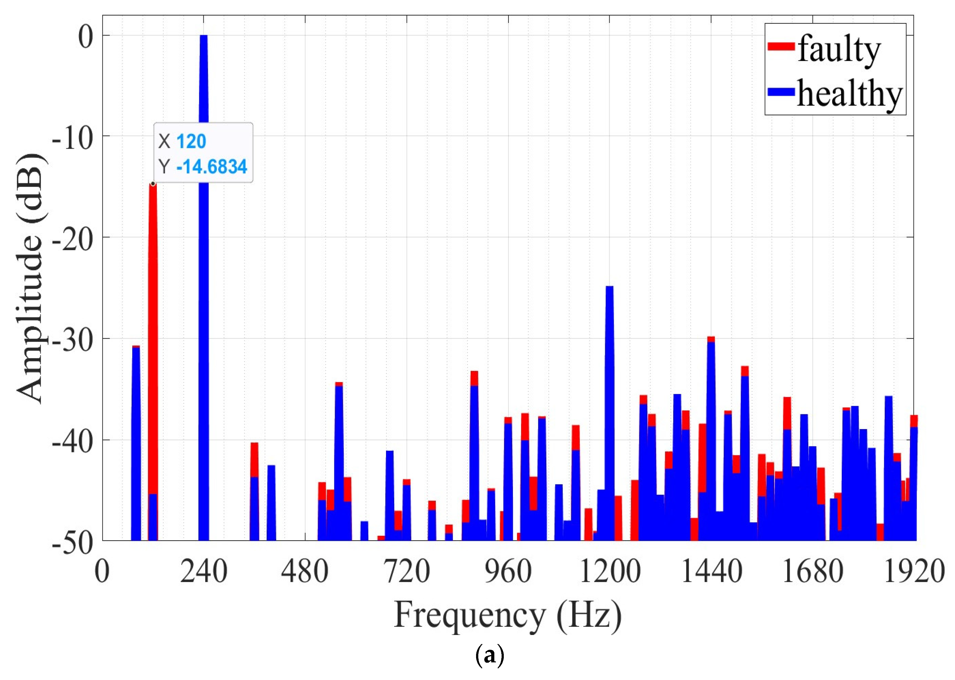
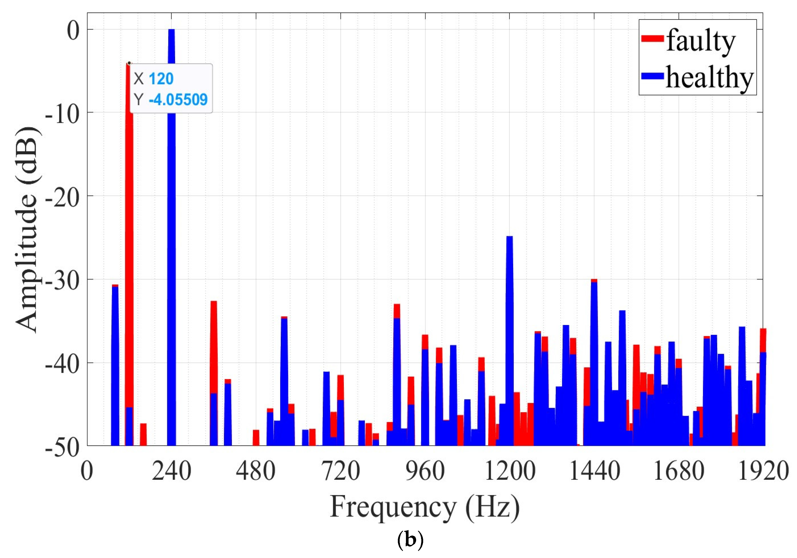
| 80 | −30.90 | −30.9 | −30.62 |
| 120 | −45.35 | −14.68 | −4.05 |
| 360 | −43.68 | −40.28 | −32.60 |
| 520 | −45.97 | −44.19 | −45.48 |
| 560 | −34.70 | −34.30 | −34.46 |
| 580 | −46.12 | −43.69 | −44.94 |
| 700 | −48.94 | −47.01 | −45.90 |
| 720 | −44.48 | −43.90 | −41.48 |
| 820 | −49.24 | −48.38 | −48.48 |
| 860 | −48.18 | −45.93 | −47.12 |
| 880 | −34.68 | −33.20 | −32.95 |
| 920 | −45.04 | −44.80 | −41.67 |
| 960 | −38.40 | −37.76 | −36.64 |
| 1000 | −40.05 | −37.38 | −38.20 |
| 1120 | −41.03 | −38.55 | −39.36 |
| 1150 | - | −46.78 | −43.99 |
| 1220 | - | −43.53 | −43.54 |
| 1260 | - | −43.98 | −44.83 |
| 1280 | −36.48 | −35.59 | −36.23 |
| 1300 | −38.67 | −37.45 | −36.87 |
| 1380 | −39.00 | −37.11 | −37.05 |
| 1420 | −45.19 | −38.41 | −40.56 |
| 1560 | −45.59 | −41.41 | −37.84 |
| 1580 | −43.51 | −42.22 | −41.17 |
| 1600 | −43.84 | −43.12 | −41.36 |
| 1620 | −38.99 | −35.77 | −38.02 |
| 1740 | −48.97 | −45.24 | −45.28 |
| 1840 | - | −48.28 | −48.36 |
| 1850 | - | −48.28 | −46.21 |
| 1920 | −38.76 | −37.56 | −35.89 |
| Frequency (Hz) | Healthy (dB) | 30% Angular Eccentricity (dB) | 40% Angular Eccentricity (dB) |
|---|---|---|---|
| 80 | −30.90 | −22.79 | −25.55 |
| 360 | −43.68 | −43.21 | −43.33 |
| 400 | −42.51 | −39.25 | −38.29 |
| 600 | - | −47.86 | −44.19 |
| 700 | −48.94 | −46.75 | −45.81 |
| 720 | −44.48 | −42.51 | −42.42 |
| 760 | - | −47.87 | −48.41 |
| 860 | −48.18 | −45.70 | −44.12 |
| 880 | −34.68 | −32.55 | −33.13 |
| 1000 | −40.05 | −38.83 | −39.93 |
| 1080 | −44.40 | −43.82 | −42.52 |
| 1220 | - | −42.58 | −45.44 |
| 1360 | −35.48 | −34.14 | −34.84 |
| 1420 | −45.19 | −42.86 | −40.13 |
| 1460 | −47.07 | −44.91 | −45.42 |
| 1480 | −37.49 | −34.50 | −34.30 |
| 1540 | −48.16 | −41.97 | −42.17 |
| 1620 | −38.99 | −38.06 | −36.52 |
| 1700 | −46.38 | −45.97 | −42.47 |
| 1880 | −42.15 | −40.74 | −40.10 |
| Frequency (Hz) | Healthy (dB) | 1 mm Axial Eccentricity (dB) | 2 mm Axial Eccentricity (dB) |
|---|---|---|---|
| 80 | −30.90 | −23.34 | −24.50 |
| 400 | −42.51 | −41.16 | −36.77 |
| 600 | - | −46.63 | −49.26 |
| 700 | −48.94 | −42.06 | −47.09 |
| 760 | - | −49.61 | −48.44 |
| 880 | −34.68 | −33.79 | −34.14 |
| 900 | −47.89 | −44.59 | −45.65 |
| 940 | - | −47.21 | −49.47 |
| 1420 | −45.19 | −44.19 | −41.38 |
| 1460 | −47.07 | −45.07 | −43.83 |
| 1480 | −37.49 | −34.31 | −35.19 |
| 1620 | −38.99 | −35.44 | −36.62 |
| 1700 | −46.38 | −40.86 | −45.76 |
| 1800 | −38.94 | −36.80 | −37.10 |
Disclaimer/Publisher’s Note: The statements, opinions and data contained in all publications are solely those of the individual author(s) and contributor(s) and not of MDPI and/or the editor(s). MDPI and/or the editor(s) disclaim responsibility for any injury to people or property resulting from any ideas, methods, instructions or products referred to in the content. |
© 2023 by the author. Licensee MDPI, Basel, Switzerland. This article is an open access article distributed under the terms and conditions of the Creative Commons Attribution (CC BY) license (https://creativecommons.org/licenses/by/4.0/).
Share and Cite
Barmpatza, A.C. The Neutral Voltage Difference Signal as a Means of Investigating Eccentricity and Demagnetization Faults in an AFPM Synchronous Generator. Machines 2023, 11, 647. https://doi.org/10.3390/machines11060647
Barmpatza AC. The Neutral Voltage Difference Signal as a Means of Investigating Eccentricity and Demagnetization Faults in an AFPM Synchronous Generator. Machines. 2023; 11(6):647. https://doi.org/10.3390/machines11060647
Chicago/Turabian StyleBarmpatza, Alexandra C. 2023. "The Neutral Voltage Difference Signal as a Means of Investigating Eccentricity and Demagnetization Faults in an AFPM Synchronous Generator" Machines 11, no. 6: 647. https://doi.org/10.3390/machines11060647