Article

Dynamic Characteristics of a Rotating Blade with a Dovetail Fixture

1
Aero Engine Corporation of China, Beijing 100097, China
2
School of Mechanics and Aerospace Engineering, Southwest Jiaotong University, Chengdu 610031, China
3
Applied Mechanics and Structure Safety Key Laboratory of Sichuan Province, Southwest Jiaotong University, Chengdu 610031, China
4
Key Laboratory of Vibration and Control of Aero-Propulsion System Ministry of Education, Northeastern University, Shenyang 110819, China
5
School of Mechanical Engineering and Automation, Northeastern University, Shenyang 110819, China
6
AECC Sichuan Gas Turbine Establishment, Mianyang 621000, China
*
Authors to whom correspondence should be addressed.
Machines 2023, 11(6), 643; https://doi.org/10.3390/machines11060643
Submission received: 6 May 2023 / Revised: 8 June 2023 / Accepted: 10 June 2023 / Published: 12 June 2023
(This article belongs to the Special Issue Research on Rotor Dynamics and Vibration Control)

Abstract

:
Considering rotation-induced centrifugal stiffening, spin softening, and Coriolis effects, the reduced dynamic model of a rotating blade with a dovetail fixture is established in the ANSYS environment via the fixed-interface method for higher computational efficiency and lower memory consumption. Then some parameters such as rotating speed, friction factor, and stator blade number affecting the nonlinear vibration responses of the system under the combined actions of aerodynamic force, centrifugal force, and gravity are elaborately discussed. The results show that: (1) the contact-induced nonlinearity between the tenon and the mortise mainly results in the frequency multiplications of the aerodynamic excitation frequency; (2) a larger friction factor results in a lower magnitude of contact pressure and a higher resonance frequency, while a larger stator blade number results in a lower magnitude of the uniform and continuous contact pressure distribution; (3) the excitation of the resonant mode caused by the aerodynamic force is primarily characterized by the first-order bending mode of the system.

1. Introduction

The blisks (for bladed discs) with mortise-tenon joints are widely used in modern aero-engines such as the fan, the compressor, and the turbine for the purpose of vibration attenuation, easy maintenance, and cost reduction. With the development of the modern aviation industry, key performance indicators such as a high thrust-to-weight ratio, low fuel consumption, and high reliability are becoming increasingly popular with aeronautical engineers, thus resulting in a much harsher working environment such as high speed, high temperature, and high load for the rotating blisk. This can easily aggravate the severe stress concentration located at the tenon joint, thus causing the blisk failure. Therefore, it is rather important to comprehensively understand their dynamic behaviors for engineering design and fault diagnosis purposes.
Numerous studies on the dynamic characteristics of the blisk with mortise-tenon joints have been published. Ma et al. [1] utilized the unreduced three-dimensional finite element model of a single blisk sector with the mortise-tenon joint fixture to study the effects of rotating speeds and penetration depths on the corresponding rubbing characteristics. Quaegebeur et al. [2] adopted the component nonlinear complex mode synthesis method integrated with the dynamic Lagrangian frequency time algorithm to analyze the effects of friction factor, rotating speed, and traveling/standing wave excitation on the amplitude-frequency responses of an industrial blisk with the mortise- tenon joint. Li et al. [3] used the plane beam elements to simulate the in-plane flapwise vibration of a mock blade with a dovetail fixture and analyzed the effects of rotating speed, friction factor, and excitation level on the amplitude-frequency curves and hysteretic characteristics of the system. In their later works [4], the incremental harmonic balance method combined with a linearization method of friction was adopted to analyze the nonlinear dynamics of the model in Ref. [3]. Considering the bending-bending-axial coupling vibration of a pre-twisted blade, She et al. [5] expanded the single blisk sector in Refs. [3,4] to the whole blisk and investigated the corresponding eigenvalues of veering and merging phenomena. Shangguan et al. [6] investigated the dynamic responses of a compressor blade with dovetail attachment under different rotating speeds from an experimental point of view, and the experimental results showed the existence of an optimal centrifugal force causing the minimal resonant amplitude and best damping effect. In their later works [7], a fractal contact friction model was introduced to describe the friction force situated at the mortise-tenon contact surfaces, and the multi-harmonic balance method combined with the Newton iterative algorithm was used to analyze the nonlinear vibration responses of a loosely assembled blade with a dovetail root. Using the one-way coupled and harmonic balance methods, Lassalle and Firrone [8] investigated the limit cycle oscillations of a blisk with a dovetail fixture caused by flutter and friction. Zucca et al. [9] developed a refined version of the state-of-the-art contact model to simulate the microslip between the blade and the disk contact surfaces and evaluated their effects on the forced responses of a blisk. Appaji et al. [10] investigated the stress state at the contact interface of a dovetail blisk attachment for varying friction factors and rotating speeds, and the results showed that the peak stress decreased with the increasing friction factor. Chen et al. [11] built the two- and three-dimensional finite element models of both simplified and realistic blade-root structures and discussed the effects of contact interface parameters, contact interface geometry, and various loading conditions on the hysteresis characteristics. In their later works [12], the high-fidelity calculation of modal damping at root joints for a lone blade as well as for a tuned blisk was performed. Using the lumped-parameter model with dry friction nonlinearity between the blade root and the disk to simulate the fundamental sector of a blisk, Joannin et al. [13] studied the forced responses and nonlinear complex modes for a tuned system under different excitation levels and for a mistuned system under random stiffness mistuning and different excitation levels. Schwarz et al. [14] carried out the nonlinear experimental modal analysis, which verified the phase-resonant method to isolate nonlinear modes in accordance with the extended periodic motion concept and the extracted nonlinear modal frequency and damping ratio in good agreement with the near-resonant frequency response tests. Based on the lumping parameter model of a single blisk sector subjected to dry damping under harmonic excitation, Liu et al. [15] used a multi-harmonic method combined with a continuation procedure to investigate the effects of excitation level, tangential stiffness of the friction model, and normal contact force on the steady vibration responses of the system. For the purpose of predicting the residual life, Canale et al. [16] adopted the commercial software FRANC3D to analyze the low cycle fatigue crack propagation of a rotating blade with a dovetail fixture, and the results showed 45° with respect to 30° and 60° flank angles and a lower friction factor resulting in a lower crack propagation rate. Yuan et al. [17] investigated a novel adaptive reduced order modeling method to reduce the high-fidelity fan blisk with dovetail joints and then analyzed the nonlinear modal characteristics under different friction factors and pre-loadings. Anandavel et al. [18] performed an analysis of the effects of preloading at the dovetail interface on the contact tractions, slip levels, and contact stress distribution for a single blisk sector, and the results indicated that the preloading effect was beneficial to reducing the peak contact pressure and stress difference between top and bottom contact edges. Fernandes et al. [19] investigated the change rules of stress intensity factors KI, KII, and KIII varying with crack width for both a single blade and a blisk using commercial software ANSYS and FRANC3D and analyzed the corresponding natural frequency changing with crack size and rotating speed. Wei et al. [20] used the finite element method to study the variation of the contact state in a dovetail attachment and pointed out that the movement of the contact edge was dominated by the relative slip and compaction of the tenon-mortise joint.
From the literature listed above, it can be concluded that most research focused on the analysis of the contact properties, hysteresis behavior located at the contact region, and modal characteristics of a single blisk sector with a dovetail fixture; however, less attention is paid to the nonlinear vibration features caused by the mortise-tenon joints, which can be rather helpful to realize the on-line monitoring and fault diagnosis. In addition, a macroslip model to describe the contact behaviors between the mortise and the tenon is relatively inaccurate, especially when quantitatively analyzing the dynamic characteristics of the rotating blisk with a dovetail fixture. In order to make up for the existing deficiencies, a single blisk sector with a dovetail fixture is taken as an example, whose three-dimensional finite element model is built via the solid and contact elements in the ANSYS environment. Then the fixed-interface method is adopted to establish the reduced blisk sector model, and the corresponding availability is verified via frequency convergence and vibration mode analysis. Next, the effects of rotating speed, friction factor, and stator blade number in front of the studied model on the nonlinear dynamic characteristics of the system under the combined action of aerodynamic force, centrifugal force and gravity are elaborately discussed. Finally, some conclusions are drawn.

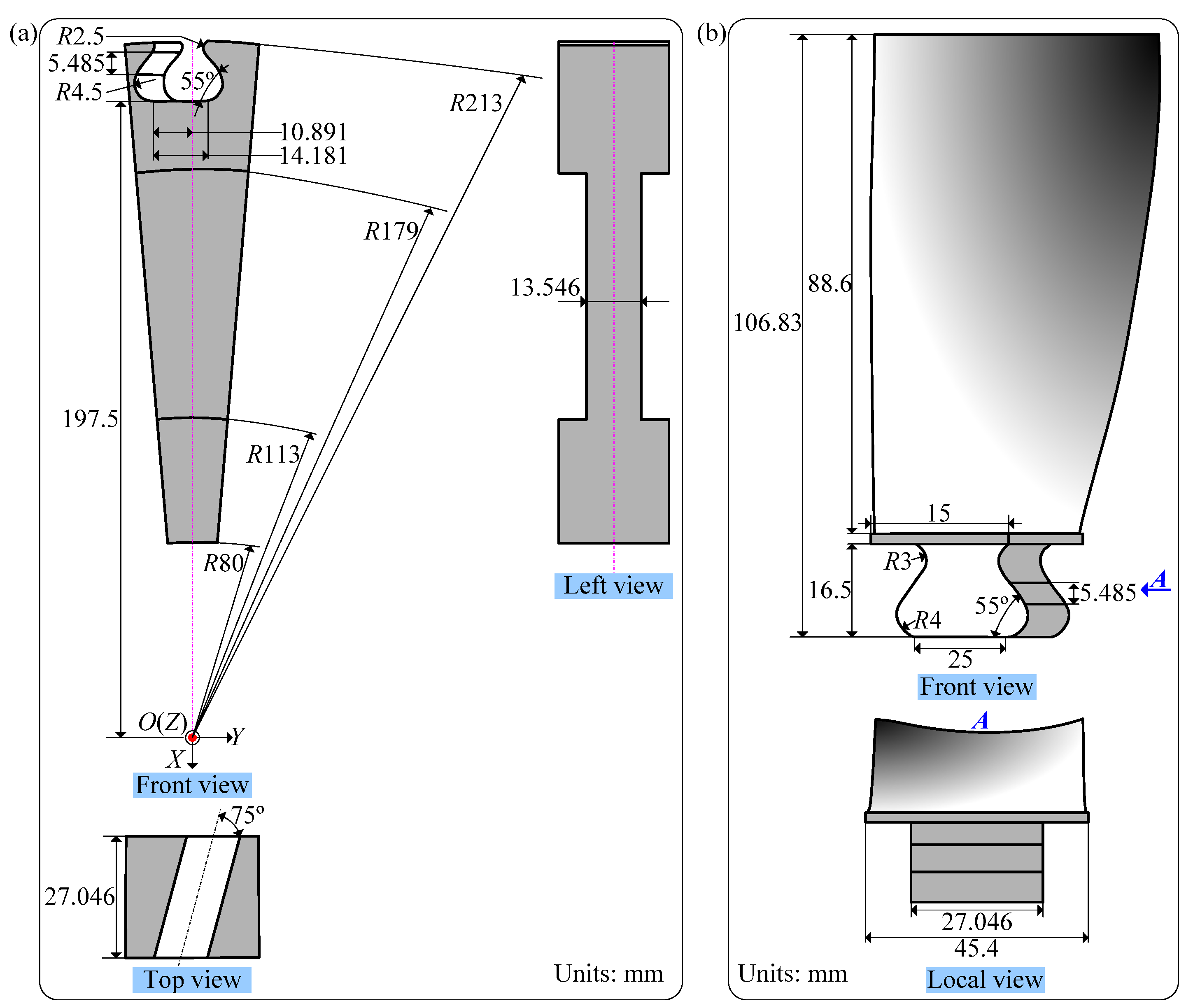
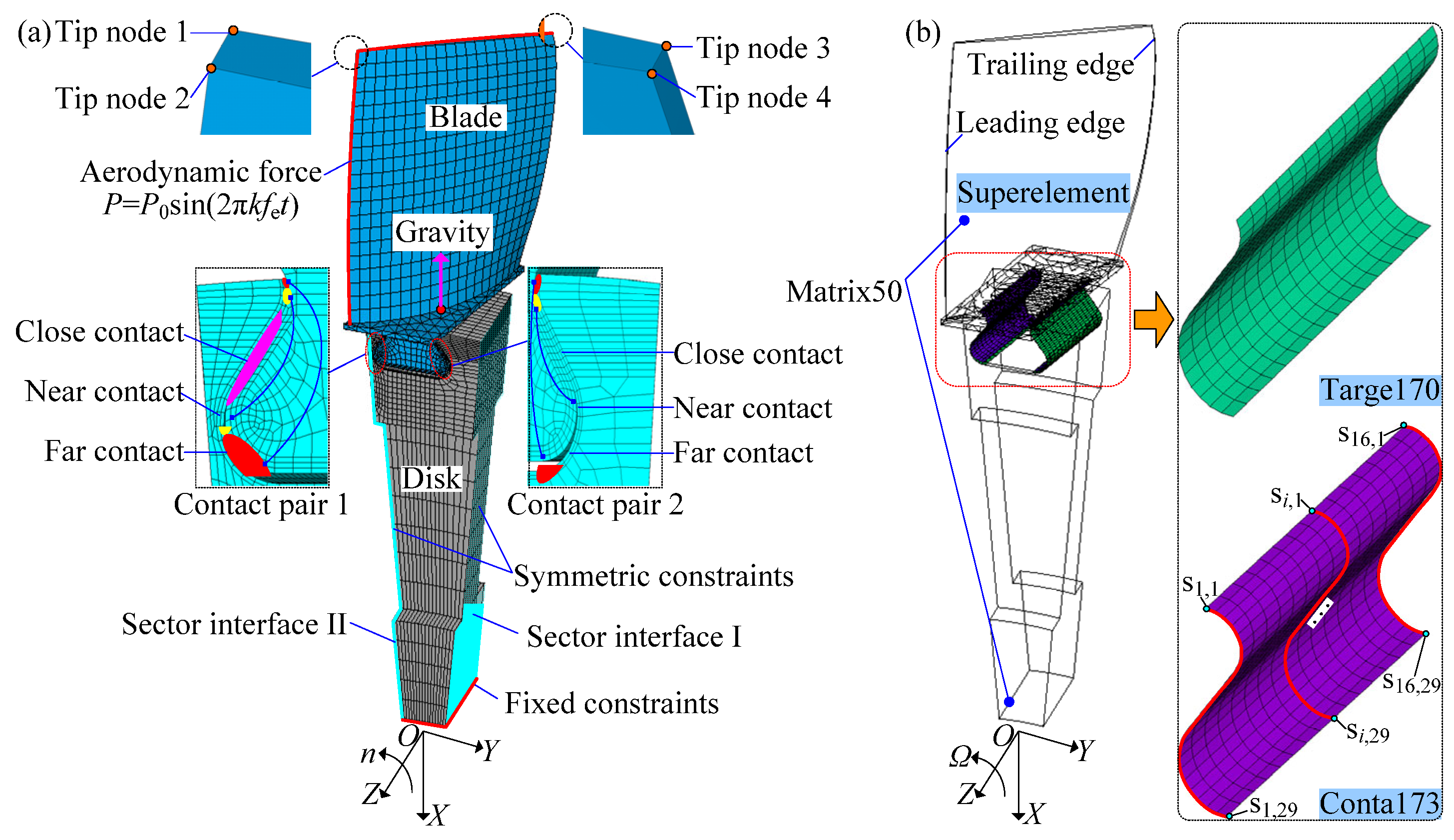
2. Finite Element Model

The geometric sizes for the disk sector and the blade made of TA11 (Ti-8Al-1Mo-1V) titanium alloy are shown in Figure 1. Then the three-dimensional finite element model of a blade with a dovetail fixture rotating at n rev/min is meshed by Solid45 elements in the ANSYS environment, and the entire model is divided into 14,746 elements and 17,019 nodes, as is shown in Figure 2a. In addition, the material properties of TA11 titanium alloy are defined as follows: Young’s modulus E = 125 GPa, Poisson’s ratio ν = 0.3, and material density ρ = 4370 kg/m3. Given that only one cyclic sector corresponding to a single blade (1/38 blisk) is included, the symmetric constraints applied to the sector interfaces I and II are considered in the Cartesian coordinate system OXYZ (see Figure 2a). Ignoring the relative motions between the disk and the shaft, the fixed constraints are applied to the inner hole of the disk sector (see Figure 2a). Here, the contact behaviors located at contact pairs 1 and 2 are simulated via the standard unilateral contact with the penalty function method, and the contact surfaces located at the tenon and the mortise are meshed by Conta173 and Targe170 elements, respectively (see Figure 2b). Besides, in order to avoid the expensive computational cost caused by the repeated contact iterations of the mortise-tenon joint, a possible initial contact configuration is artificially adjusted according to their geometric details under the influence of centrifugal force, i.e., the close contact, the near contact, and the far contact in Figure 2a. Furthermore, the effects of both the simplified aerodynamic force P = P0·sin(2πkfrt) acting on the pressure surface and the gravity acting on the whole model are included (see Figure 2a). Here, P0, k, fr, and t represent the aerodynamic amplitude, the number of stator blades in front of the studied model, rotational frequency (i.e., fr = n/60 Hz), and time, respectively.
In light of the large number of degrees of freedom and nonlinearity induced by two contact pairs in the model (see Figure 2), the fixed-interface method is then utilized to reduce the model for improving computation efficiency and decreasing memory consumption with the goal of ensuring model accuracy. Generally, the equations of motion of the full model in Figure 2a can be written as follows:
M u ¨ + D u ˙ + K u = F D = D R + C K = K e + K s + K c F = P + F cen + F con
where  M D R C K e K s , and  K c  are the mass, Rayleigh damping, Coriolis, structural stiffness, centrifugal stiffening, and spin softening matrices, respectively; Fcen and Fcon are the centrifugal and contact force vectors, respectively;  u ¨ u ˙ , and  u  are the acceleration, velocity, and displacement vectors, respectively; D, K, and F are the combinations of relevant matrices, respectively. Here, the expression of DR is further shown below:
D R = α M + β K α = 2 ξ 2 / ω 2 ξ 1 / ω 1 / 1 / ω 2 2 1 / ω 1 2 β = 2 ξ 2 ω 2 ξ 1 ω 1 / ω 2 2 ω 1 2
where ω1 = 2πf1 and ω2 = 2πf2 are the first two-order natural circular frequencies corresponding to n, while f1 and f2 are the corresponding natural frequencies, respectively; α and β are the mass and stiffness matrix multipliers for the damping, respectively; ξ1 and ξ2 are the first two-order modal damping ratios, respectively. In this paper, ξ1 = ξ2 = 0.03 is assumed.
In terms of the fixed-interface method, the degree of freedoms (DoFs) of the studied model in Equation (1) are first separated into slave and master DoFs. The corresponding adjusted equations of motion are then written as follows:
M ss M sm M ms M mm u ¨ s u ¨ m + D ss D sm D ms D mm u ˙ s u ˙ m + K ss K sm K ms K mm u s u m = F s F m
where the subscripts ‘s’ and ‘m’ represent the slave and master DoFs, respectively. In this study, the tip nodes 1, …, 4 (see Figure 2a) and contact nodes located at the contact pairs 1, 2 (see Figure 2b) are set as master nodes, while the others are defined as slave nodes.
According to the principle of the fixed-interface method, the relationship between the physical DoFs u and the generalized DoFs q can be written as follows:
u = u s u m = Φ ss j s Φ sm 0 ms I mm q s q m = Φ q
where  Φ ss = K ss 1 K sm Φ ss j s  is the retained first-js order fixed interface normal modes.
Substituting Equation (4) into Equation (3), the equations of motion of the reduced model in Figure 2b can then be expressed as follows:
M ^ q ¨ + D ^ q ˙ + K ^ q = F ^
where  M ^ = Φ T M Φ D ^ = Φ T D Φ , and  K ^ = Φ T K Φ . Here, it should be noted that the matrix dimension in Equation (5) is (m + js).
In Figure 2b, the reduced model obtained from the fixed-interface method is characterized by the Matrix50 element, while the nonlinear contact between the mortise and the tenon is still simulated via the Conta173 and Targe170 elements. Furthermore, it is worth noting that si,j in Figure 2b is used to extract the contact pressure of the jth node at the ith section of the contact surface, which varies with time in the following analysis.

3. Dynamic Characteristic Analysis

This section will discuss the influences of js, rotating speed n, friction factor μ, and the number of stator blades in front of the studied model k on the dynamic characteristics of the model. The corresponding simulation parameters are listed in Table 1.

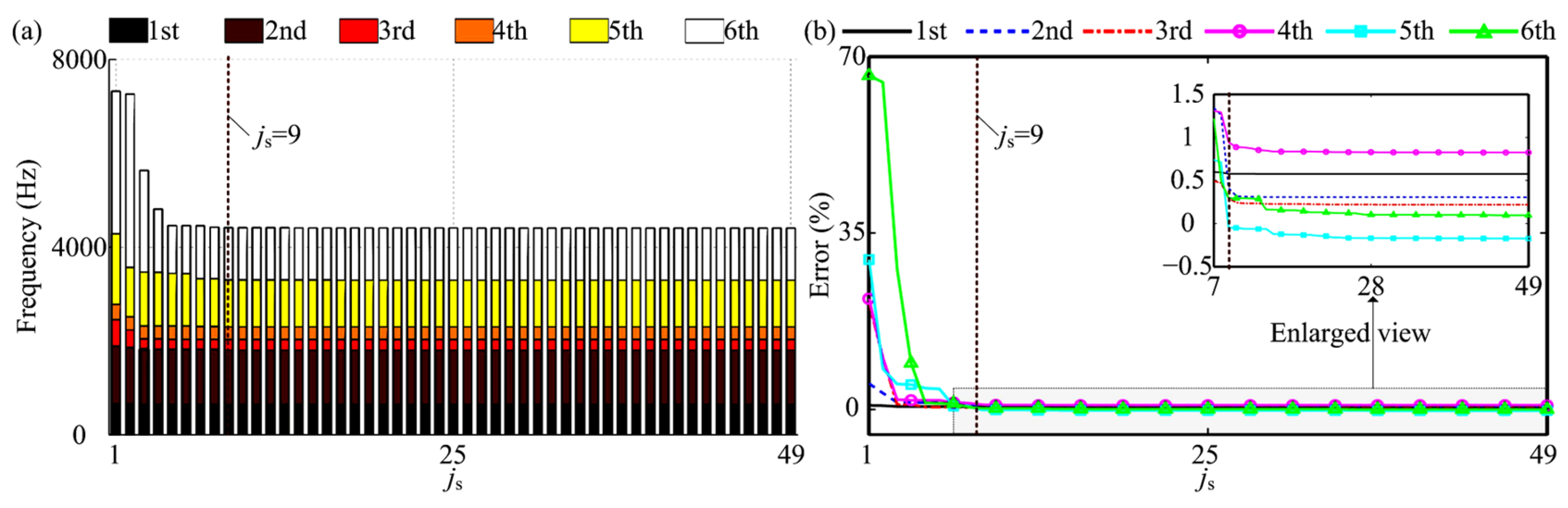
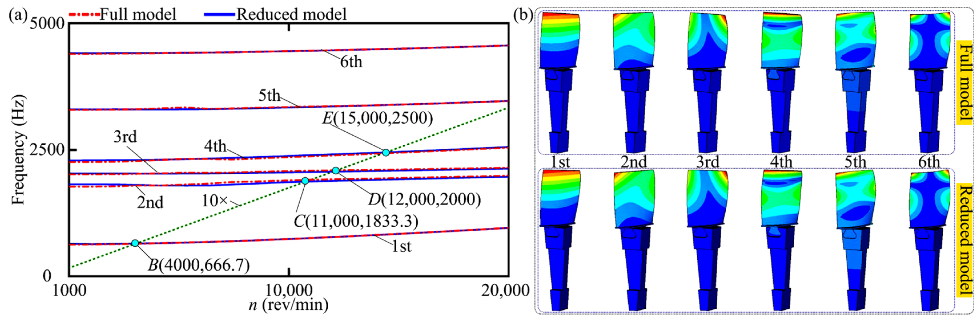
3.1. Modal Characteristics

(1) Case 1: effects of the number of normal modes js
When n = 4000 rev/min, the effects of js on the first-six-order natural frequencies are shown in Figure 3. Corresponding simulation parameters are shown in Case 1 in Table 1. It can be seen from Figure 3a that with increasing js, all the first-six-order natural frequencies are gradually convergent. Especially when js ≥ 9, the natural frequencies are almost unchanged. Taking the results of the full model under n = 4000 rev/min as a benchmark, the frequency error varying with js is shown in Figure 3b. The results indicate that the maximum error for the first-six-order natural frequencies is no more than 1% when js ≥ 9. Based on this, js = 10 is then adopted in the following study.
(2) Case 2: effects of the rotating speed n
The first-six-order natural frequencies obtained from the full and reduced models varying with n are shown in Figure 4a. Corresponding model parameters can be found in Case 2 in Table 1. It can be seen from the figure that the natural frequencies of each order increase with the increase of n. Corresponding modal shapes under n = 4000 rev/min are plotted in Figure 4b. As a whole, both the dynamic frequencies and modal shapes obtained from both models show good agreement with each other. However, it takes about 80 s for the reduced model and 120 s for the full model. This strongly shows that the reduced model has good precision and a low computational cost. In Figure 4a, it can be seen that fe = 10fr results in the four possible resonance points within n∈[1000, 20,000] rev/min, i.e., A (4000 rev/min, 649.4 Hz), B (11,000 rev/min, 1867.8 Hz), C (12,000 rev/min, 2064.5 Hz), and D (15,000 rev/min, 2454.3 Hz) (see Figure 4a).

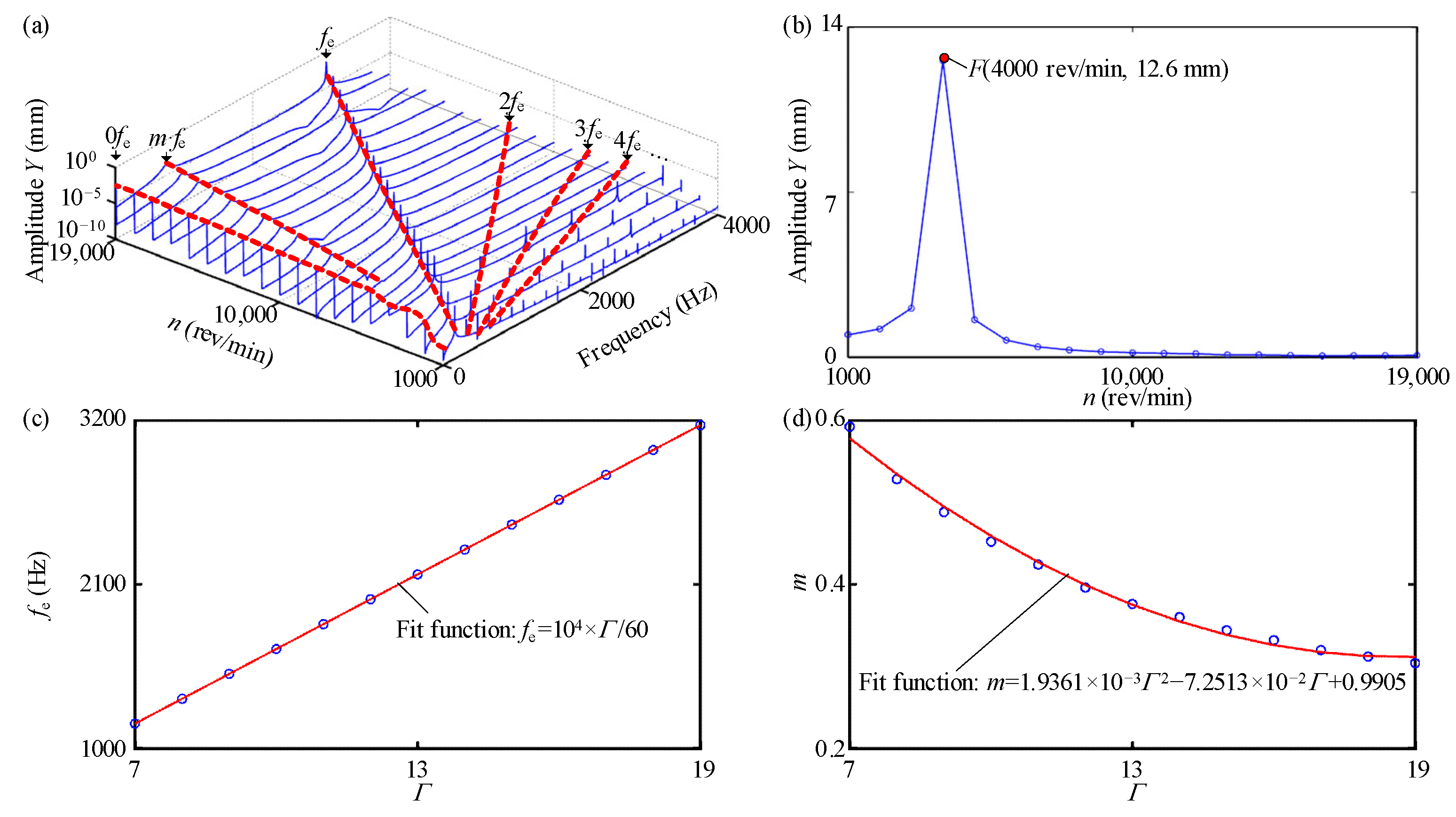
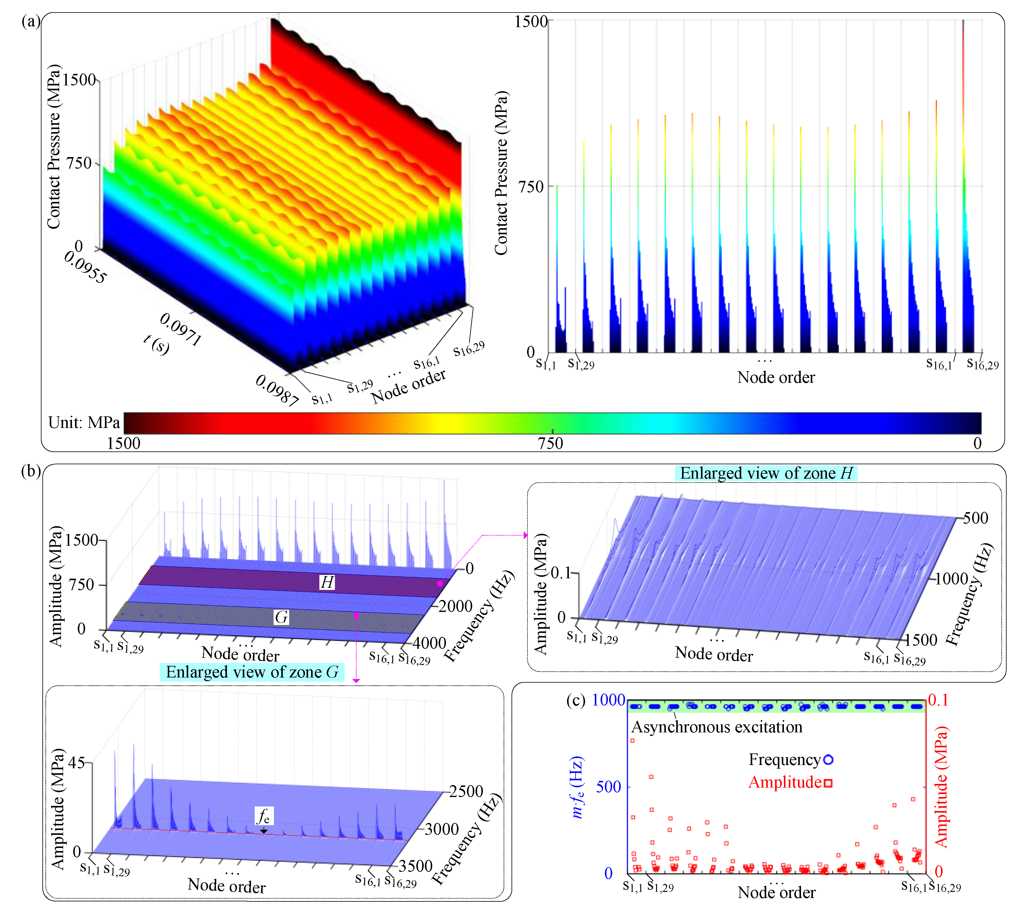
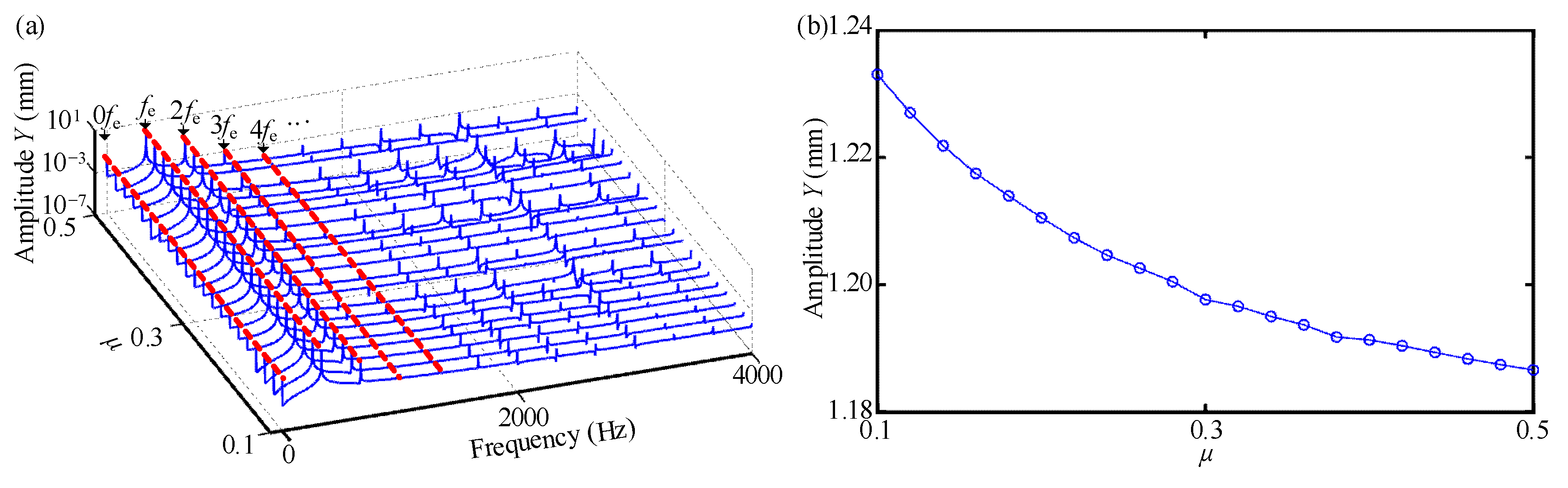
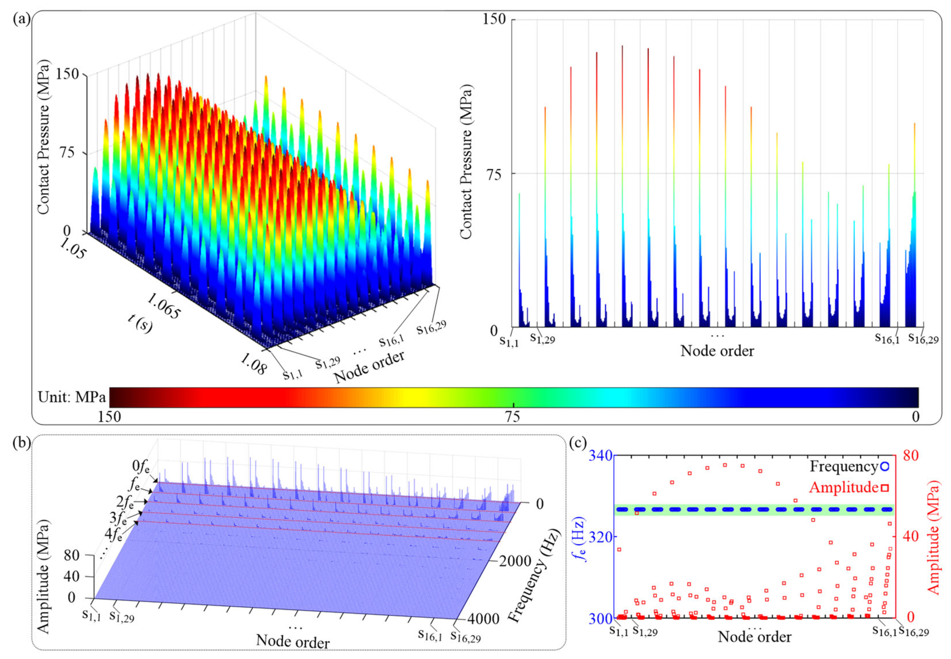
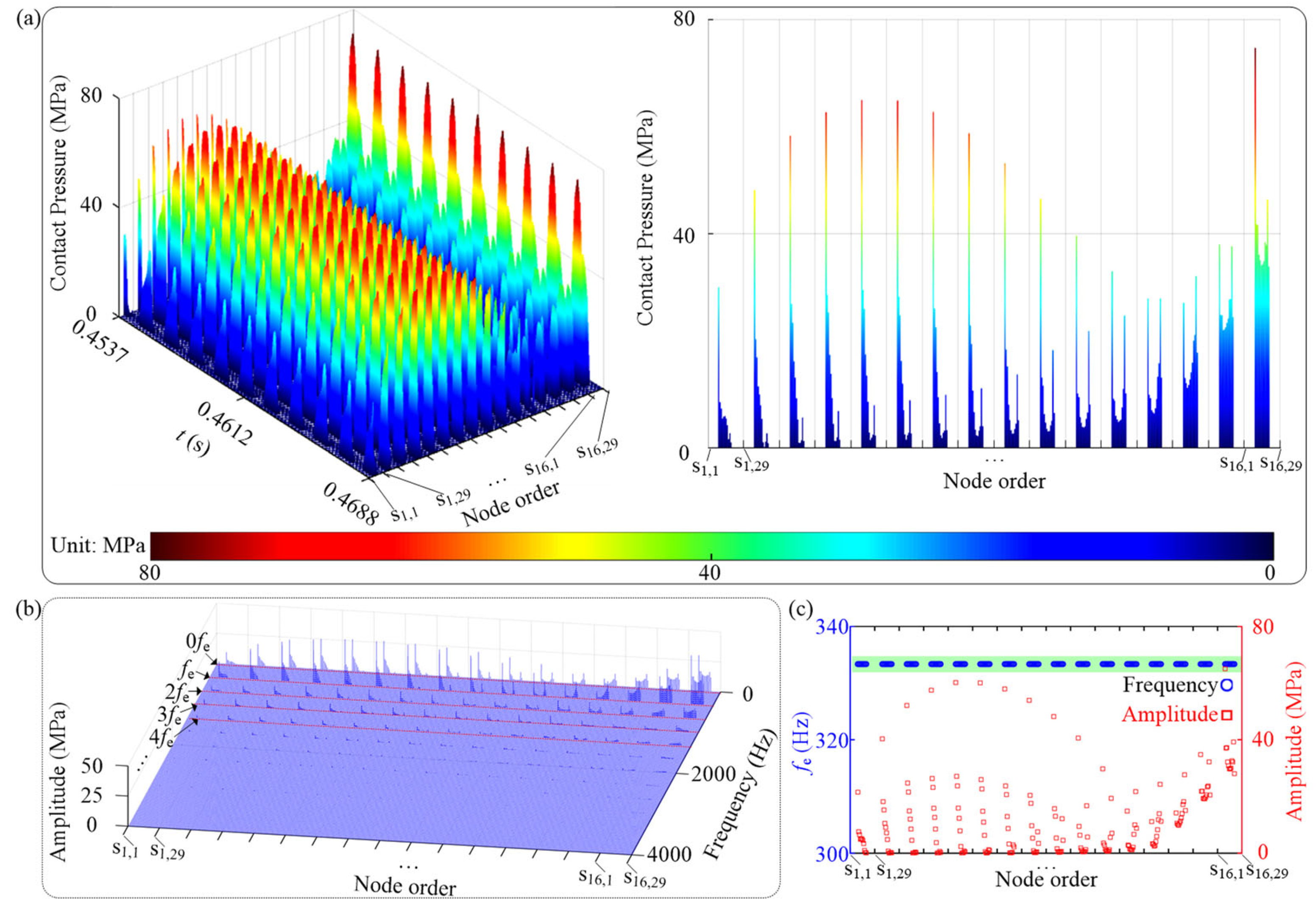
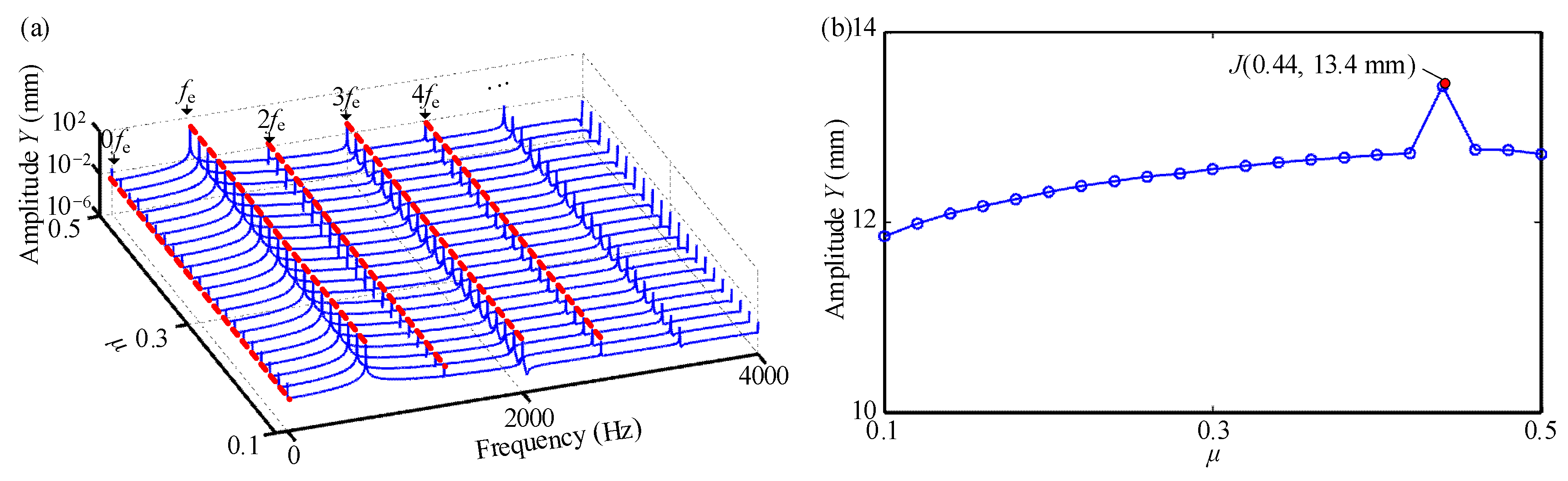
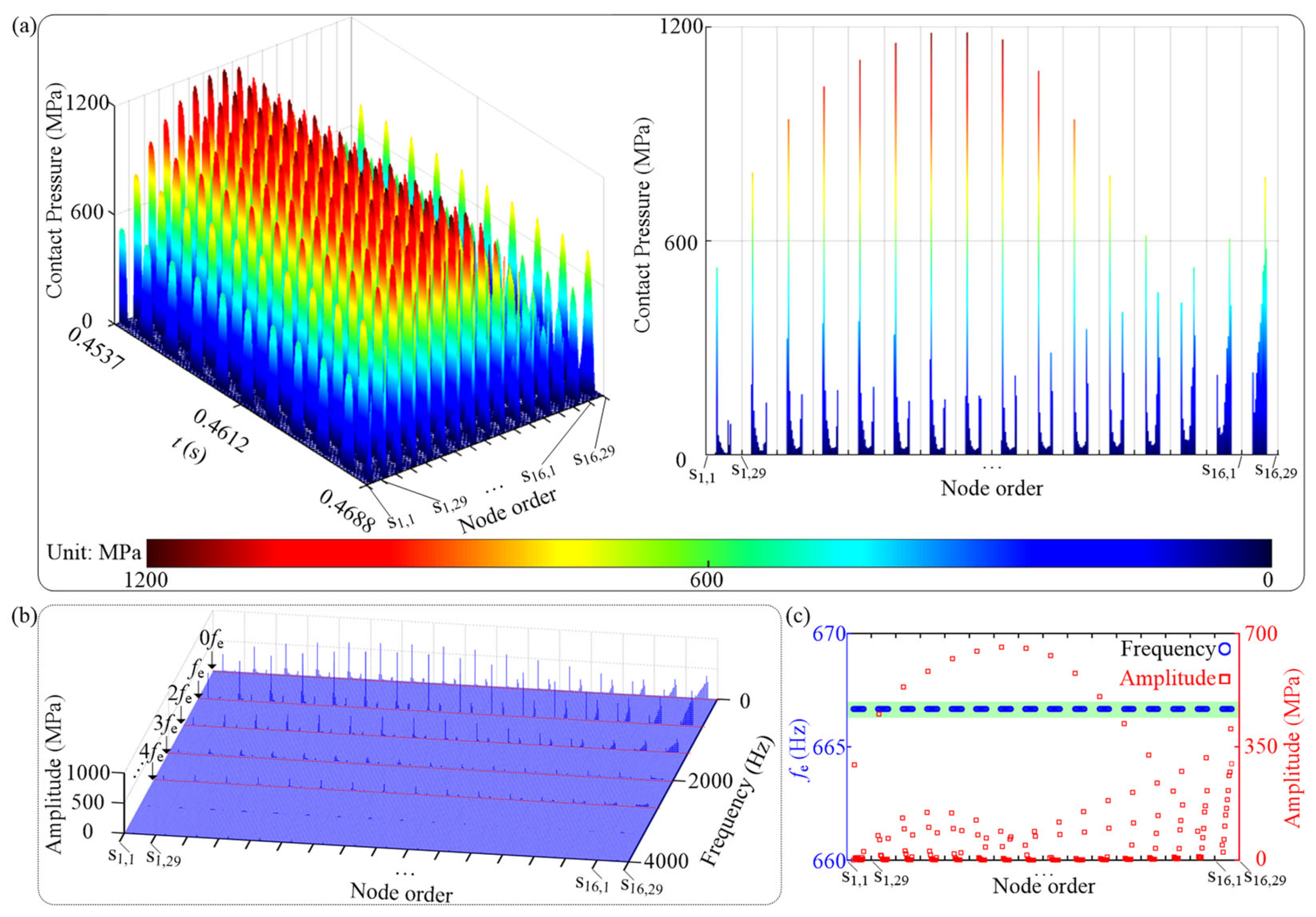
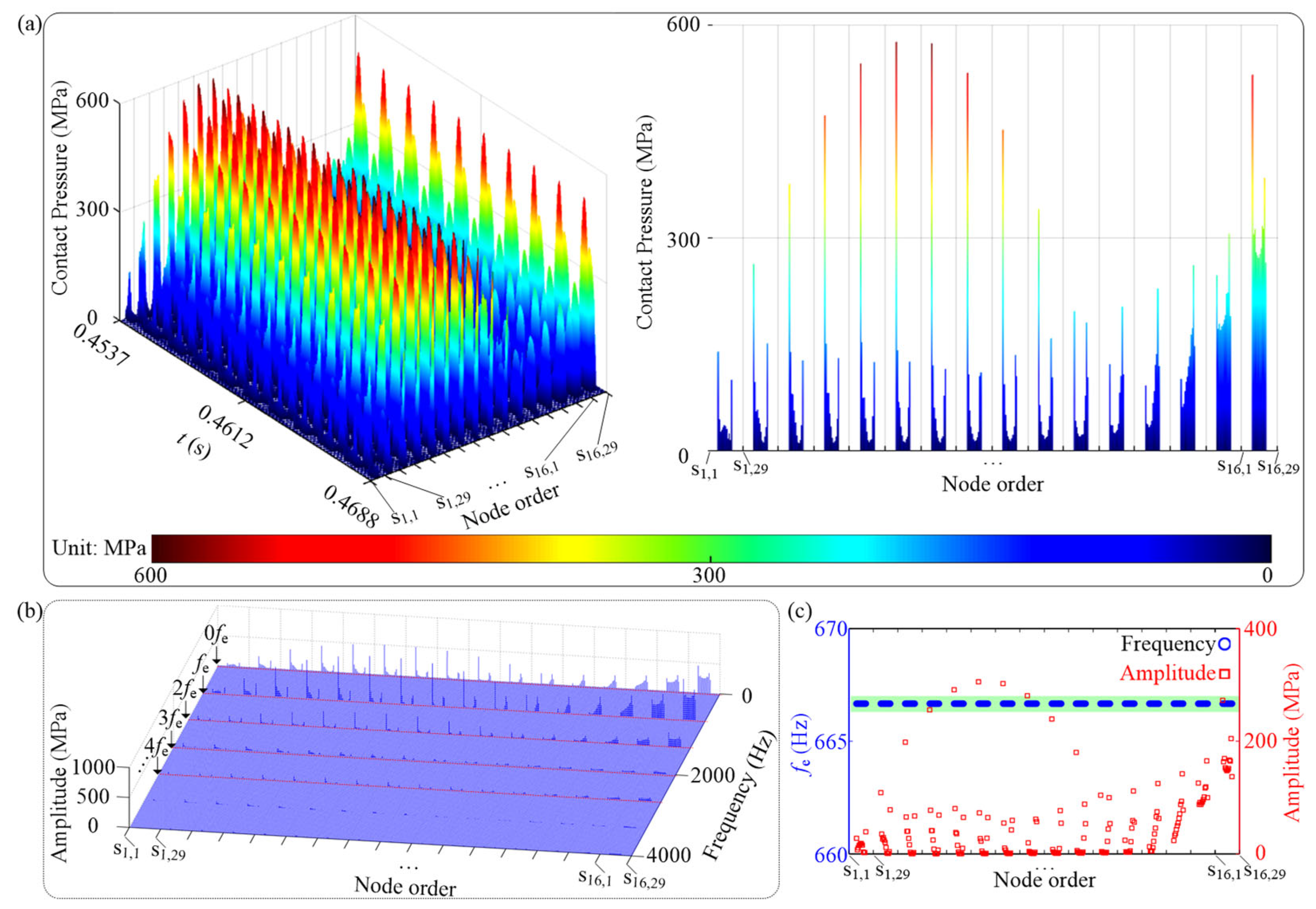
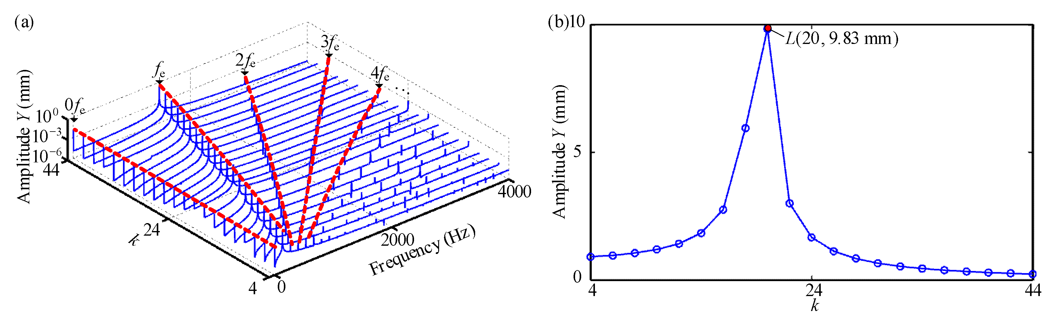
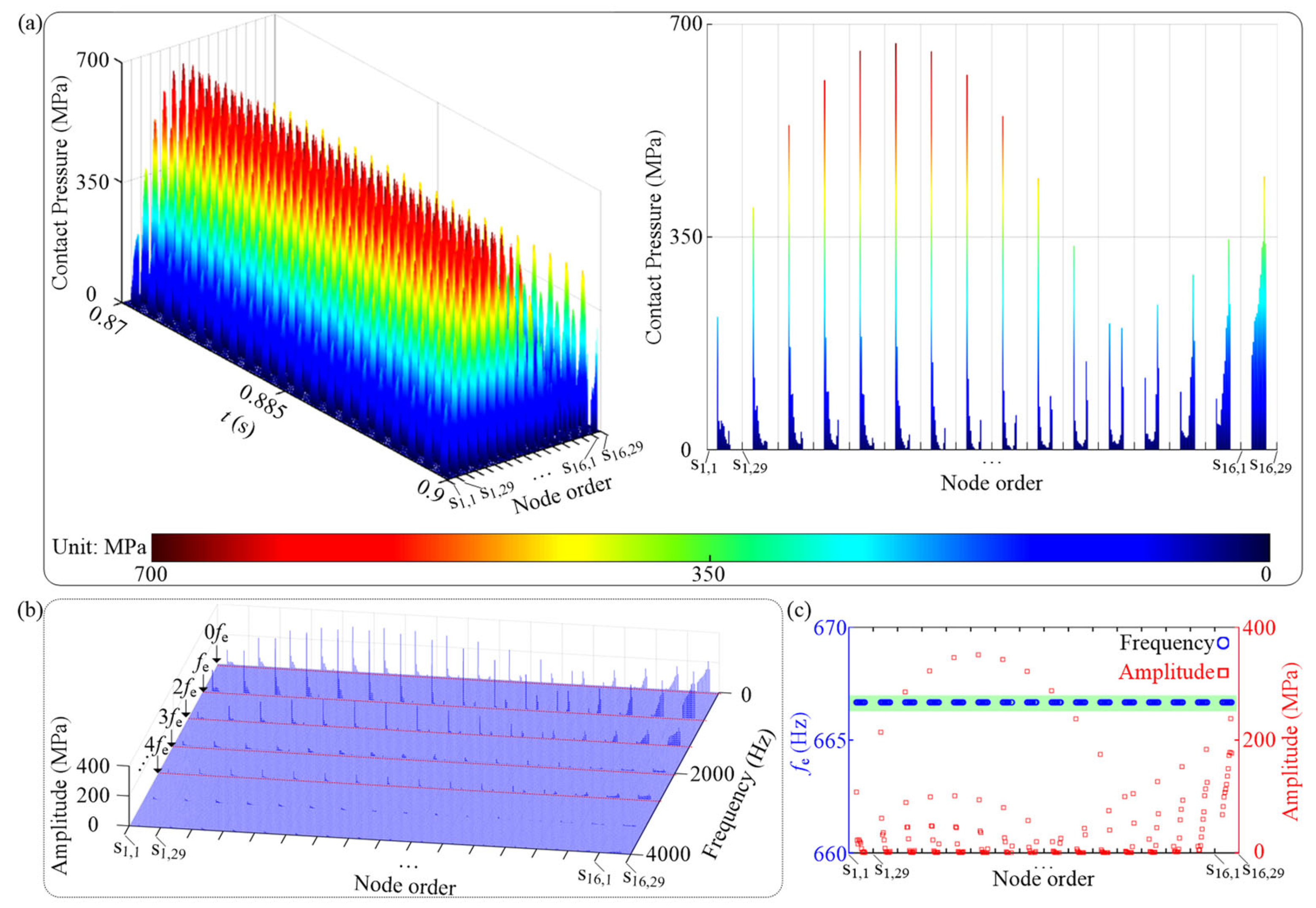
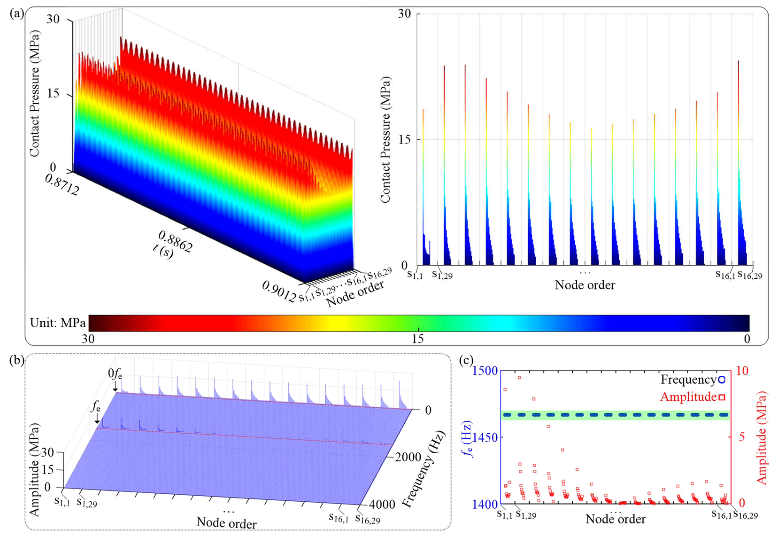
3.2. Nonlinear Vibration Characteristics

(1) Case 3: effects of the rotating speed n
In this section, the simulation parameters of the system are shown in Case 3 in Table 1. Then the Y-spectrum of tip node 1 (see Figure 2a) extracted from the last 25 rotation periods (i.e., 25 × 1/fr s) is plotted in Figure 5a. Besides fe in Figure 5a, there are multiple frequency components (i.e., 2fe, 3fe, 4fe, …) when n∈[1000, 5000] rev/min, and this indicates that the model has strong nonlinearity under the action of aerodynamic force. With increasing n, the high multiple frequency components disappear when n∈[6000, 19,000] rev/min, and this indicates that the nonlinearity of the model is weakened and even disappears. In Figure 5b, the amplitude Y at fe varies with n is depicted. The figure shows that the resonance point is F(4000 rev/min, 12.6 mm), and this is in accordance with the results shown in Figure 4a. A particularly interesting phenomenon is that there exists a frequency component m·fe. Here, both fe and m varying with a normalized parameter Γ (Γ = n/1000) are plotted in Figure 5c,d, respectively. It can be seen from the figures that the variation of fe has good agreement with those obtained from the fit function 104 × Γ/60, i.e., fe is the actual aerodynamic excitation frequency, while m in Figure 5d varies with Γ.
In order to further clarify the above issues, some in-depth analyses are made. In terms of the nonlinearity phenomenon presented in Figure 5a, the corresponding explanations are given below: the centrifugal force under low rotating speeds is relatively small, thus leading to more intermittent contacts between the mortise and the tenon than under high rotating speeds, which directly cause the impulse and continuous contact force distributions located at the tenon joint interfaces under the action of the aerodynamic force, respectively (see Figure 6a and Figure 7a). The vibration responses of the contact pressure for contact pair 1 (see Figure 2a) under n = 4000 rev/min and 19,000 rev/min are taken as examples (see Figure 6 and Figure 7), respectively. In Figure 6a, the contact pressure has obvious impulse characteristics, thus leading to a strong broadband excitation, and the corresponding spectrum cascade in Figure 6b also illustrates it. Here, it is worth noting that the node order in Figure 6 can refer to Figure 2b. The spectrum cascades related to Figure 6a are shown in Figure 6b. Besides fe, there are high multiple frequencies such as 2fe, 3fe, 4fe, …, and a constant frequency component 0fe, and this is in accordance with the spectrum distribution in Figure 5a. In addition, both the frequency and amplitude at fe varying with n are extracted, as shown in Figure 6c. The figure shows that fe at all the contact nodes is in good agreement with 104 × Γ/60, and the maximum contact pressure is no more than 600 MPa.
The contact pressure distribution under n = 19,000 rev/min is shown in Figure 7. In Figure 7a, the contact pressure has obvious continuous harmonics with a non-zero mean value. This indicates that the mortise and the tenon are always in contact with each other, thus weakening the nonlinearity of the model. The spectrum cascades in Figure 7b show that the amplitude at 0fe caused by high centrifugal force is much larger than that at other frequencies, and this also indicates that the close contact between interfaces will weaken the nonlinearity of the rotating blade with a dovetail fixture. In addition, fe at all the nodes in region G is always stable at 104 × Γ/60, which indicates a frequency-locking phenomenon. However, the frequency at all the nodes in region H is fluctuant (see Figure 7c), which indicates an asynchronous excitation. The phenomenon strongly illustrates that single pair rather than distributed contact pairs is actually inaccurate to simulate the interactions between the mortise and the tenon.
(2) Case 4: effects of the friction factor μ
The discussion made in the foregoing analysis indicates that the relatively low rotating speed results in the rich dynamic behaviors of the studied system. Based on this, n = 2000 rev/min and 4000 rev/min (resonance speed in Figure 5b) are taken as typical examples to further understand the nonlinear vibration responses of the studied system under various μ. Corresponding parameter settings can be found in Case 4 in Table 1.
When n = 2000 rev/min, the Y-vibration responses of tip node 1 and the vibration responses of contact pressure for contact pair 1 are shown in Figure 8, Figure 9 and Figure 10. The spectrum cascades in Figure 8a indicate that nonlinearity induced by the tenon and the mortise only results in integer multiples of fe under the combined effect of aerodynamic force, centrifugal force, and gravity. The amplitude-frequency curve in Figure 8b shows that the vibration amplitude of tip node 1 is decreasing with increasing μ. The colormaps of contact pressure for contact pair 1 in Figure 9 and Figure 10 indicate that the increasing μ causes the decreasing amplitude of contact pressure. Besides, a larger μ leads to a more prominent contribution to contact pressure within the contact zone for contact pair 1 close to the trailing edge of the blade (see Figure 2b, Figure 9 and Figure 10). In addition, fe in Figure 9c and Figure 10c has a good frequency-locking feature and is always stable at 333.33 Hz.
When n = 4000 rev/min, the effects of μ on the Y-vibration responses of tip node 1 are shown in Figure 11. In Figure 11a, besides 0fe, it is mainly reflected in the frequency multiplication of fe (i.e., 2fe, 3fe, 4fe, …). It seems that the increasing μ (μ∈[0.1, 0.5]) has little impact on the spectrum distribution (see Figure 11a). The corresponding amplitude-frequency curves are shown in Figure 11b. Compared with Figure 5b, it can be concluded that the increasing μ results in the right shift of the resonance point (i.e., F(0.3, 12.6 mm)→J(0.44, 13.4 mm)) thus showing a hard nonlinearity phenomenon. The vibration responses of contact pressure for contact pair 1 under μ = 0.1, 0.3, and 0.44 are shown in Figure 12, Figure 6 and Figure 13, respectively. It can be concluded from the figures that with increasing μ, the amplitude of contact pressure is decreasing. In addition, the frequency components of contact pressure consist of 0fe, 1fe, 2fe, 3fe, 4fe,…, and fe is maintained at 333.33 Hz. In addition, comparing Figure 12 (Figure 13) with Figure 9 (Figure 10), it can be observed that a larger n results in a larger amplitude of contact pressure, but the increasing n seemingly has no effect on the distribution rules of contact pressure when intermittent contact between the tenon and the mortise occurs.
(3) Case 5: effects of the number of stator blades in front of the studied model k
In this section, the effects of k on the dynamic characteristics of the studied system are elaborately analyzed. Corresponding parameter settings are listed in Case 5 in Table 1. In Figure 14a, besides the constant value component 0fe in the spectrum cascades, there are also integer multiples of fe such as 2fe, 3fe, 4fe, and so on. The amplitude-frequency curve in Figure 14b indicates that there is a resonance point L(20, 9.83 mm), and the corresponding resonance frequency is about 666.7 Hz, close to the first-order natural frequency of the studied system (referring to Figure 4). Then the distribution rules of contact pressure for contact pair 1 under k = 20 and 24 are taken as examples to analyze corresponding contact characteristics, as is shown in Figure 15 and Figure 16. It can be seen from the figures that with increasing k, the time domain waveform of the contact pressure is gradually changing from intermittent to continuous. Moreover, a larger k results in a relatively uniform distribution of contact pressure between the tenon and the mortise. Moreover, compared with Figure 15b and Figure 16b, the disappearance of multiple frequency components in the spectrum cascades illustrates that the nonlinearity of the studied system will be weakened under a larger k. Owing to the uniform distribution of contact pressure located at the contact surfaces under a larger k, the magnitude of contact pressure is generally smaller than that under a smaller k.

4. Conclusions

In this paper, the three-dimensional finite element model of a rotating blade with a dovetail fixture is established via the commercial software ANSYS. In order to improve computational efficiency, the fixed-interface method is then used to reduce the model under the premise of assuring the model’s accuracy, and the effects of the number of normal modes on the first six-order dynamic frequencies and modal shapes are elaborately discussed. Then the effects of rotating speed, friction factor, and the number of stator blades on the nonlinear dynamic characteristics of the studied model are studied. Some main conclusions are summarized as follows:
(1) Under low rotating speeds, the intermittent contact between interfaces results in frequency multiplications in the spectrum cascades; under high rotating speeds, the distributed contact within contact regions results in asynchronous excitation, thus leading to a complicated frequency distribution.
(2) A larger friction factor results in a more prominent contribution to the magnitude of the contact pressure close to the trailing edge of the blade. Furthermore, the larger the friction factor is, the lower the magnitude of the contact pressure. Moreover, the increasing friction factor results in a higher resonance frequency, characterizing a hard nonlinearity phenomenon.
(3) The increasing number of stator blades make the time-domain waveform of the contact pressure change from an intermittent contact state to a continuous contact state. Moreover, a larger stator blade number of results in a relatively uniform distribution of contact pressure between the tenon and the mortise, thus resulting in a lower contact pressure magnitude.

Author Contributions

Conceptualization, J.Z. and Y.Y.; methodology, J.Z. and H.M.; software, J.Z. and W.L.; validation, X.F.; formal analysis, J.Z., H.M., X.F., C.F. and S.F.; resources, C.F. and S.F.; data curation, J.Z. and W.L.; writing—original draft preparation, X.F.; writing—review and editing, X.F., J.Z., C.F. and S.F.; visualization, X.F., W.L., C.F. and S.F.; funding acquisition, J.Z., Y.Y. and C.F. All authors have read and agreed to the published version of the manuscript.

Funding

This research was funded by the National Natural Science Foundation (Grant nos. 12202368, 12172307), the Natural Science Foundation of Sichuan Province (Grant nos. 22NSFSC0576, 22NSFSC0666, 2023NSFSC0068), the Opening Project of Applied Mechanics and Structure Safety Key Laboratory of Sichuan Province (No. SZZZKT-202206), the Key Laboratory of Vibration and Control of Aero-Propulsion System, Ministry of Education, Northeastern University of China (No. VCAME202205, VCAME202103), and the Fundamental Research Funds for the Central Universities (Grant nos. 2682021CX081, 2682021ZTPY036).

Data Availability Statement

Not applicable.

Conflicts of Interest

The authors declare no conflict of interest.

References

  1. Ma, H.; Wang, D.; Tai, X.Y.; Wen, B.C. Vibration response analysis of blade-disk dovetail structure under blade tip rubbing condition. J. Vib. Control 2017, 23, 252–271. [Google Scholar] [CrossRef]
  2. Quaegebeur, S.; Chouvion, B.; Thouverez, F. Nonlinear dynamic analysis of three-dimensional bladed-disks with frictional contact interfaces based on cyclic reduction strategies. Int. J. Solids Struct. 2022, 236–237, 111277. [Google Scholar] [CrossRef]
  3. Li, C.F.; Shen, Z.C.; Zhong, B.F.; Wen, B.C. Study on the nonlinear characteristics of a rotating flexible blade with dovetail interface feature. Shock. Vib. 2018, 2018, 4923898. [Google Scholar] [CrossRef]
  4. Li, C.F.; Liu, X.W.; Tang, Q.S.; Chen, Z.L. Modeling and nonlinear dynamics analysis of a rotating beam with dry friction support boundary conditions. J. Sound Vib. 2021, 498, 115978. [Google Scholar] [CrossRef]
  5. She, H.X.; Li, C.F.; Tang, Q.S.; Wen, B.C. Veering and merging analysis of nonlinear resonance frequencies of an assembly bladed disk system. J. Sound Vib. 2021, 493, 115818. [Google Scholar] [CrossRef]
  6. Shangguan, B.; Xu, Z. Experimental study of friction damping of blade with loosely assembled dovetail attachment. Proc. Inst. Mech. Eng. Part A J. Power Energy 2012, 226, 738–750. [Google Scholar] [CrossRef]
  7. Shangguan, B.; Yu, F.L.; Duan, J.Y.; Gao, S.; Xiao, J.F. A fractal contact friction model and nonlinear vibration response studies of loosely assembled blade with dovetail root. In Proceedings of the ASME Turbo Expo 2016: Turbomachinery Technical Conference and Exposition, Seoul, Republic of Korea, 13–17 June 2016. [Google Scholar]
  8. Lassalle, M.; Firrone, C.M. A parametric study of limit cycle oscillation of a bladed disk caused by flutter and friction at the blade root joints. J. Fluids Struct. 2018, 76, 349–366. [Google Scholar] [CrossRef]
  9. Zucca, S.; Firrone, C.M.; Gola, M.M. Numerical assessment of friction damping at turbine blade root joints by simultaneous calculation of the static and dynamic contact loads. Nonlinear Dyn. 2012, 67, 1934–1955. [Google Scholar] [CrossRef]
  10. Appaji Gowda, B.M.; Yeshovanth, H.R.; Siddaraju, C. Investigation and efficient modeling of an dovetail attachment in aero-engine. Procedia Mater. Sci. 2014, 5, 1873–1879. [Google Scholar] [CrossRef] [Green Version]
  11. Chen, J.J.; Zang, C.P.; Zhou, B.; Petrov, E.P. A study of friction microslip modeling for dynamic analysis of bladed discs with root joints. J. Mech. Eng. Sci. 2018, 233, 2599–2641. [Google Scholar] [CrossRef]
  12. Chen, J.J.; Zang, C.P.; Zhou, B.; Petrov, E.P. High-fidelity calculation of modal damping caused by friction at blade roots for single blades and tuned bladed disc assemblies. Proc. Inst. Mech. Eng. Part C J. Mech. Eng. Sci. 2021, 235, 2810–2831. [Google Scholar] [CrossRef]
  13. Joannin, C.; Chouvion, B.; Thouverze, F.; Mbaye, M.; Ousty, J.P. Nonlinear modal analysis of mistuned periodic structures subjected to dry friction. J. Eng. Gas Turbines Power 2016, 138, 072504. [Google Scholar] [CrossRef] [Green Version]
  14. Schwarz, S.; Kohlmann, L.; Hartung, A.; Gross, J.; Scheel, M.; Krack, M. Validation of a turbine blade component test with frictional contacts by phase-locked-loop and force-controlled measurements. J. Eng. Gas Turbines Power 2020, 142, 051006. [Google Scholar] [CrossRef]
  15. Liu, T.Y.; Zhang, D.; Xie, Y.H. A nonlinear vibration analysis of forced response for a bladed-disk with dry friction dampers. J. Low Freq. Noise Vib. Act. Control 2019, 38, 1522–1539. [Google Scholar] [CrossRef]
  16. Canale, G.; Kinawy, M.; Maligno, A.; Sathujoda, P.; Citarella, R. Study of mixed-mode cracking of dovetail root of an aero-engine blade like structure. Appl. Sci. 2019, 9, 3825. [Google Scholar] [CrossRef] [Green Version]
  17. Yuan, J.; Schwingshackl, C.; Salles, L.; Wong, C.; Patsias, S. Reduced order method based on an adaptive formulation and its application to fan blade system with dovetail joints. In Proceedings of the ASME Turbo Expo 2020: Turbomachinery Technical Conference and Exposition, London, UK, 22–26 June 2020. [Google Scholar]
  18. Anandavel, K.; Prakash, R.V.; Davis, A. Effect of preloading on the contact stress distribution of a dovetail interface. World Acad. Sci. Eng. Technol. 2010, 4, 1107–1112. [Google Scholar]
  19. Fernandes, R.; El-Borgi, S.; Ahmed, K.; Friswell, M.I.; Jamia, N. Static fracture and modal analysis simulation of a gas turbine compressor blade and bladed disk system. Adv. Model. Simul. Eng. Sci. 2016, 3, 30. [Google Scholar] [CrossRef] [Green Version]
  20. Wei, D.S.; Ma, M.D.; Zhang, H.; Hu, C.; Wang, Y.R. Study of the variation of contact state near the contact boundary in a dovetail attachment under different loads. Eng. Fail. Anal. 2019, 105, 518–526. [Google Scholar] [CrossRef]
Figure 1. Geometric size: (a) disk sector, (b) blade.
Machines 11 00643 g001
Figure 2. Finite element model of a rotating blade with a dovetail fixture: (a) full model, (b) reduced model.
Machines 11 00643 g002
Figure 3. Effects of js on the first six-order frequencies under n = 4000 r/min: (a) frequency convergency; (b) error curve.
Machines 11 00643 g003
Figure 4. Modal characteristics varying with n: (a) Campbell diagram, (b) modal shape under n = 4000 rev/min.
Machines 11 00643 g004
Figure 5. Y-vibration of tip node 1: (a) spectrum cascades; (b) amplitude frequency responses; (c) fe vs. Γ; (d) m vs. Γ.
Machines 11 00643 g005
Figure 6. Vibration responses of contact pressure for contact pair 1 under n = 4000 rev/min: (a) time waveform, (b) spectrum cascades, (c) fe and corresponding amplitude vs. node order.
Machines 11 00643 g006
Figure 7. Vibration responses of contact pressure for contact pair 1 under n = 19,000 rev/min: (a) time waveform, (b) spectrum cascades, (c) m·fe and corresponding amplitude vs. node order.
Machines 11 00643 g007
Figure 8. Y-vibration characteristics of tip node 1 when n = 2000 rev/min: (a) spectrum cascades, (b) amplitude-frequency responses.
Machines 11 00643 g008
Figure 9. Vibration responses of contact pressure for contact pair 1 under μ = 0.1 when n = 2000 rev/min: (a) time waveform, (b) spectrum cascades, and (c) fe and corresponding amplitude vs. node order.
Machines 11 00643 g009
Figure 10. Vibration responses of contact pressure for contact pair 1 under μ = 0.44 when n = 2000 rev/min: (a) time waveform, (b) spectrum cascades, and (c) fe and corresponding amplitude vs. node order.
Machines 11 00643 g010
Figure 11. Y-vibration characteristics of tip node 1 when n = 4000 rev/min: (a) spectrum cascades, (b) amplitude-frequency responses.
Machines 11 00643 g011
Figure 12. Vibration responses of contact pressure for contact pair 1 under μ = 0.1 when n = 4000 rev/min: (a) time waveform, (b) spectrum cascades, and (c) fe and corresponding amplitude vs. node order.
Machines 11 00643 g012
Figure 13. Vibration responses of contact pressure for contact pair 1 under μ = 0.44 when n = 4000 rev/min: (a) time waveform, (b) spectrum cascades, and (c) fe and corresponding amplitude vs. node order.
Machines 11 00643 g013
Figure 14. Y-vibration characteristics of tip node 1: (a) spectrum cascades; (b) amplitude-frequency responses.
Machines 11 00643 g014
Figure 15. Vibration responses of contact pressure for contact pair 1 under k = 20: (a) time waveform, (b) spectrum cascades, and (c) fe and corresponding amplitude vs. node order.
Machines 11 00643 g015
Figure 16. Vibration responses of contact pressure for contact pair 1 under k = 44: (a) time waveform, (b) spectrum cascades, and (c) fe and corresponding amplitude vs. node order.
Machines 11 00643 g016
Table 1. Simulation parameters.
CasesAnalysis TypeGravityConstant ParametersVarying Parameters
1Prestressed modalNon = 4000 rev/min, μ = 0.3, P0 = 0 MPajs∈[1, 49], Δjs = 1;
2js = 10, μ = 0.3, P0 = 0 MPan∈[1000, 20,000] rev/min,
Δn = 1000 rev/min;
3TransientYesjs = 10, P0 = 0.1 MPa, μ = 0.3, k = 10fe = k·fr, n∈[1000, 20,000] rev/min, Δn = 1000 rev/min;
4js = 10, P0 = 0.1 MPa, k = 10fe = k·fr, n = 2000 rev/min, 4000 rev/min;
μ∈[0.1, 0.5], Δμ = 0.02
5js = 10, P0 = 0.1 MPa, n = 2000 rev/min, μ = 0.3fe = k·fr, k∈[4, 44] rev/min, Δk = 2
Disclaimer/Publisher’s Note: The statements, opinions and data contained in all publications are solely those of the individual author(s) and contributor(s) and not of MDPI and/or the editor(s). MDPI and/or the editor(s) disclaim responsibility for any injury to people or property resulting from any ideas, methods, instructions or products referred to in the content.

