1. Introduction
The automotive industry (AI) is one of the most innovative, competitive and economically important sectors worldwide [
1]. In the last decade, it has experience constant growth, producing around 91.8 million vehicles during the year 2019 [
2]. In the decade between 2010–2019, it showed constant growth, stabilizing in 2020 and showing a downward trend in the last two years [
3]. This drop is related to the lack of definition in terms of vehicle motorization, as well as the pandemic situation experienced between 2020 and 2022 and the Russia–Ukraine conflict in 2022–2023, situations that induced a sudden rise in inflation, with a particular focus on fossil fuels and energy. Moreover, environmental concerns also affect this sector [
4]. These data are particularly important to put into perspective the coming years, which are approaching as challenging ones [
5]. However, AI has always shown the ability to reinvent itself, and this is, effectively, a transition situation [
6].
The most competitive companies have two fundamental characteristics in their production processes, namely flexibility and agility, which allow them to be prepared for constant changes that the market is currently undergoing [
7,
8,
9,
10]. Industrial flexibility is the ability of a company to deal with variations in the components or products within its manufacturing processes, such as changes in raw materials, product size and weight, geometry and changes in product complexity [
11,
12,
13]. Flexibility, in addition to allowing the system to absorb product variations, also possesses the ability to minimize interruptions in production changeovers [
14,
15,
16]. These systems can produce different types of parts or, when they become obsolete, be easily converted, covering new needs [
17,
18,
19]. Industrial agility reflects the ability of companies to react quickly to market needs or to new levels of quality and innovation presented by competitors, maintaining their capacity to follow new market trends without losing competitiveness [
19].
Studies on wire bending mainly focus on phenomena related to fatigue [
20,
21,
22,
23,
24,
25,
26,
27,
28,
29]. As in other types of mechanical analyses, the simulation was also applied to wires to predict their behavior in certain loading cases, both in the form of wire and steel cables [
30,
31,
32]. There are still studies on the manipulation of steel bent wires, both in the manipulation of wires to feed plastic injection equipment [
33] and in the organization of wires in wire-bending equipment [
34]. Moreover, the damping of the oscillation effect in the wire-bending process has also been studied [
35]. However, research on wire and steel cable bending is very scarce, making this subject more attractive in terms of research due to the market’s need to solve numerous problems related to this area of the industry. In addition, the automotive industry uses numerous products that base their working principle on steel cables or bent wires, such as Bowden cables and comfort systems related to the support of motor vehicle seats [
36,
37].
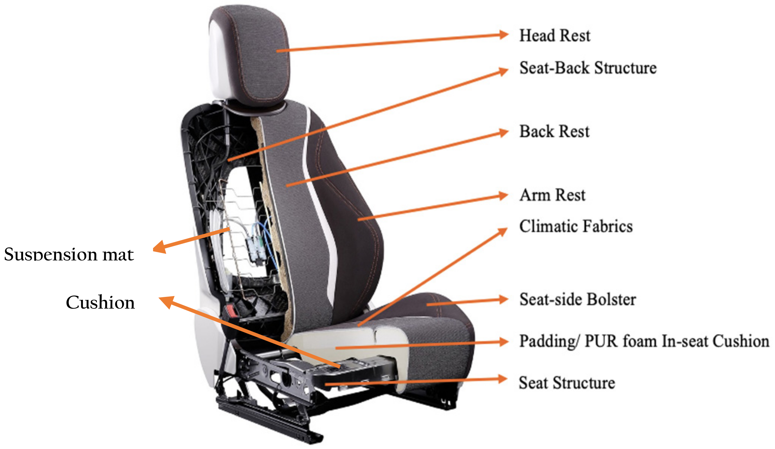
Indeed, cars are is made up of several components that complement each other. One of these components is the seat, which is one of the key elements of the safety and comfort of occupants. This makes it possible to ensure that the occupants remain solid with the structure of the car in the event of accidents or sudden movements. In addition to all the safety requirements that a seat must guarantee, it must ensure the comfort of its occupants, for both short and long trips, reducing the maximum the vibrations caused by the track, as well as by the various components that make up the seat.
Figure 1 illustrates the main components that make up a car seat:
In the cushion/suspension mat manufacturing industry, a significant loss of competitiveness was identified in the wire-bending process, as it had very flexible equipment with little productivity and equipment with high productivity, in which the implementation of new projects is quite expensive, i.e., they had poor flexibility. There exists equipment on the market that is flexible and has good productivity but has some limitations in terms of the manufacturing of wires for car seat comfort systems, namely in the minimum dimension between folds in the central part of the cushions/suspension mats. This equipment usually has two bending tools controlled by CNC and a wire rotation system positioned between the tools [
39,
40,
41]. These rotation systems usually limit the size of the wire in the central part. This identified the literature gap in the development of automatic wire-bending systems for the automotive industry and justifies the development of this work. It then became necessary to think of a new system from scratch, while taking advantage of some of the existing concepts. To this end, the subsystems presenting characteristics that fit the new wire-bending philosophy to be implemented were firstly identified. Thus, the strengths and weaknesses of the equipment on the market and in the industry were dissected through a benchmark that included the systems that fit the development to be carried out, as well as the typical characteristics of cushions/suspension mats. After selecting these subsystems, they were integrated into an innovative concept that yields levels of flexibility and productivity not achieved so far.
A new concept was then developed following design science research (DSR) [
42,
43,
44,
45], which integrated some existing subsystems with others developed from scratch, forming a set that responds to the intended requirements. DSR is a methodology used to develop new products from existing ones and can also be applied in other types of situations. Teixeira et al. [
46] refers to DRS as a useful methodology due to its “technological background and its focus on developing models and methods that address complex and ill-defined problems”. Siedhoff [
47] developed a new sequence of nominal processes for DSR based on the work of Devitt and Robbins [
48] to be implemented after general problem identification, combining design thinking with pre-existing DSR phases, including research activities and the cycle principle. The process was divided into exploration (problem clarification/definition and solution establishment) and prescriptive investigation, which, as shown by Peffers et al. [
49] and Lepenioti et al. [
50], are solution recommendations that lead to optimal decision making ahead of time. For the development of the new concept of wire bending used in the cushion manufacturing industry, the DSR methodology used by Siedhoff [
46], as well as by Tojal et al. [
51], was realized as the best option. It was intended to design an evolution of the previous equipment, creating a new concept while incorporating some knowledge previously acquired.
This work also wants to show that it is possible to develop equipment with high flexibility and high productivity following the right methodology because the product is properly known.
2. Benchmarking: Concepts Existing on the Market
The market presents several solutions to bending metallic wire, ranging from the most generic equipment, which customers have to adapt themselves to the features of the equipment and create products based on their limitations, to the most personalized equipment that seeks to satisfy some of the most particular needs of customers, being much more flexible. Because this flexibility is sufficient for almost all applications, these devices do not always have the necessary productivity. The continuous use of this type of equipment and deeper knowledge of the products and techniques needed to make them translate into knowledge that can be used to develop even more flexible and productive equipment. Thus, benchmarking is then carried out on the existing equipment on the market with a qualitative evaluation of the same, showing the capabilities and limitations.
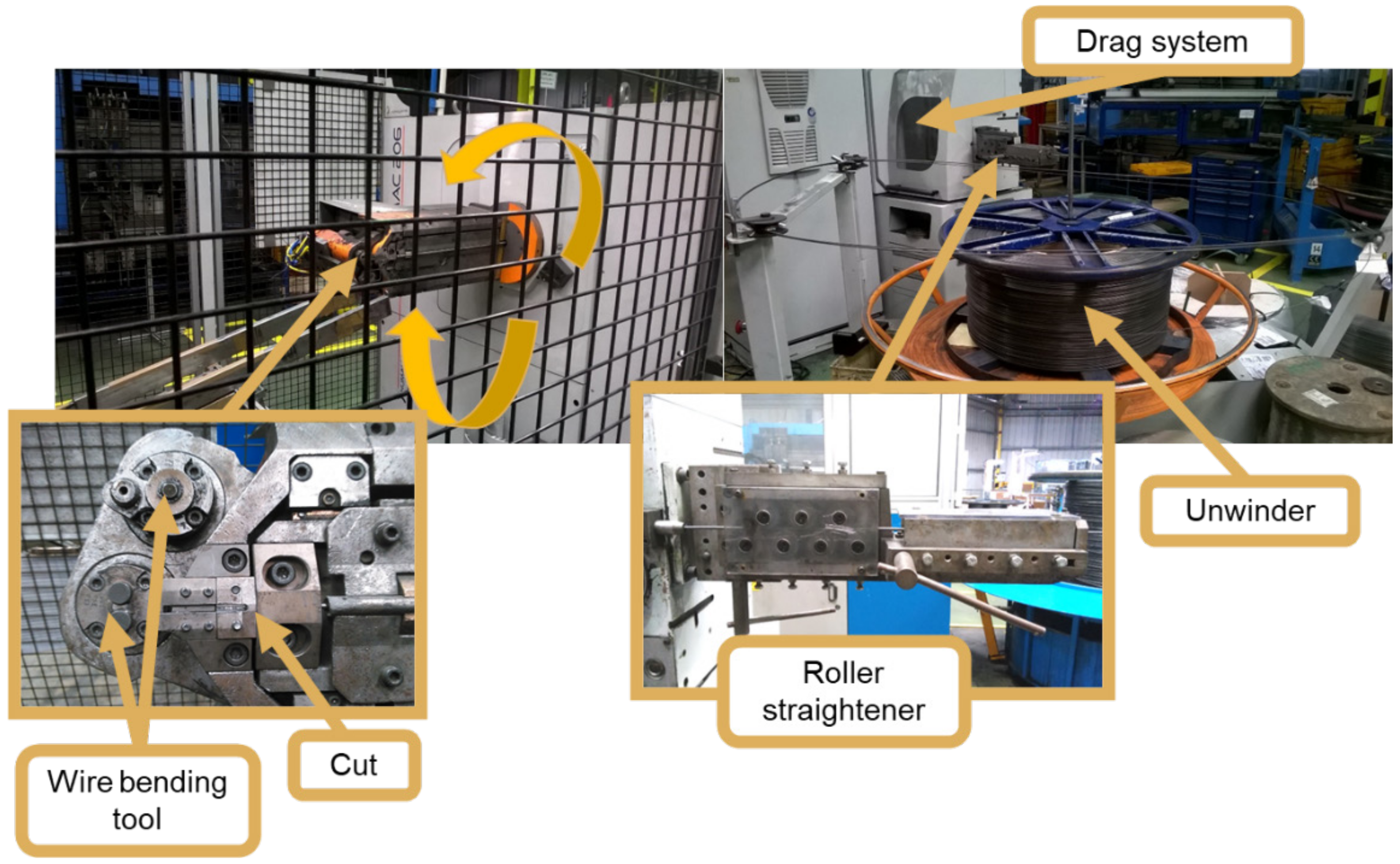
The wire-bending machines shown in
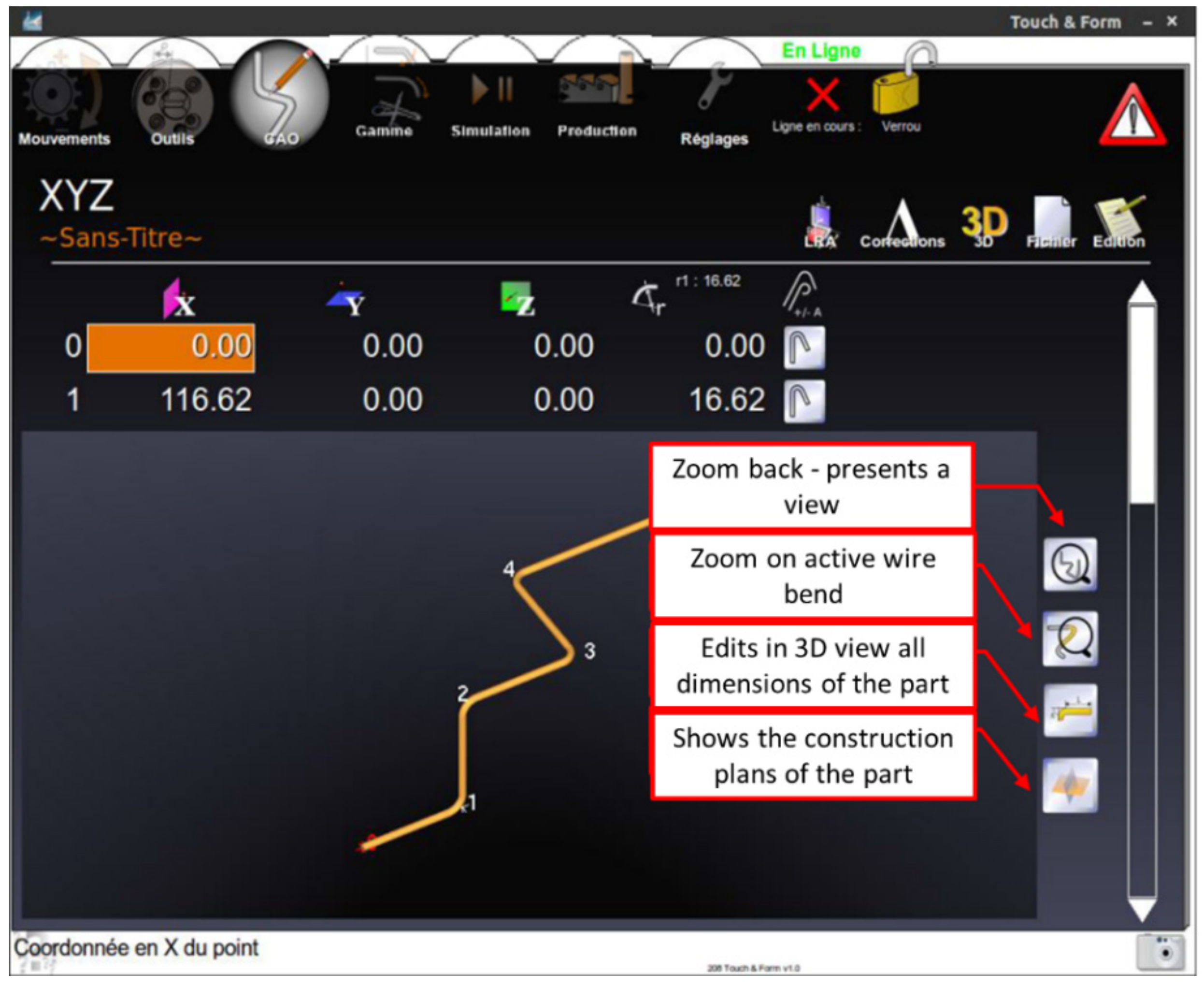
Figure 2 are the most versatile and intuitive machines on the market (Robomac concept). They consist of the following features: (a) a motorized unwinder; (b) a two-plane roller straightener; (c) a drag system with four drive wheels; (d) an encoder; and (e) a cutting system and two folding heads. The wire is pulled by the drag system, straightening the wire on the roller straightener, thus arriving perfectly straight at the bending tools. The machine is only capable of performing a single bend at each step; thus, the subproduct remains suspended under its weight during the last bends. These machines have a very intuitive and accessible interface for the user, allowing a 3D perspective of the wire (
Figure 3) and adjustment based on the dimensions of the wire, rather than the positional reference of the bending tools.
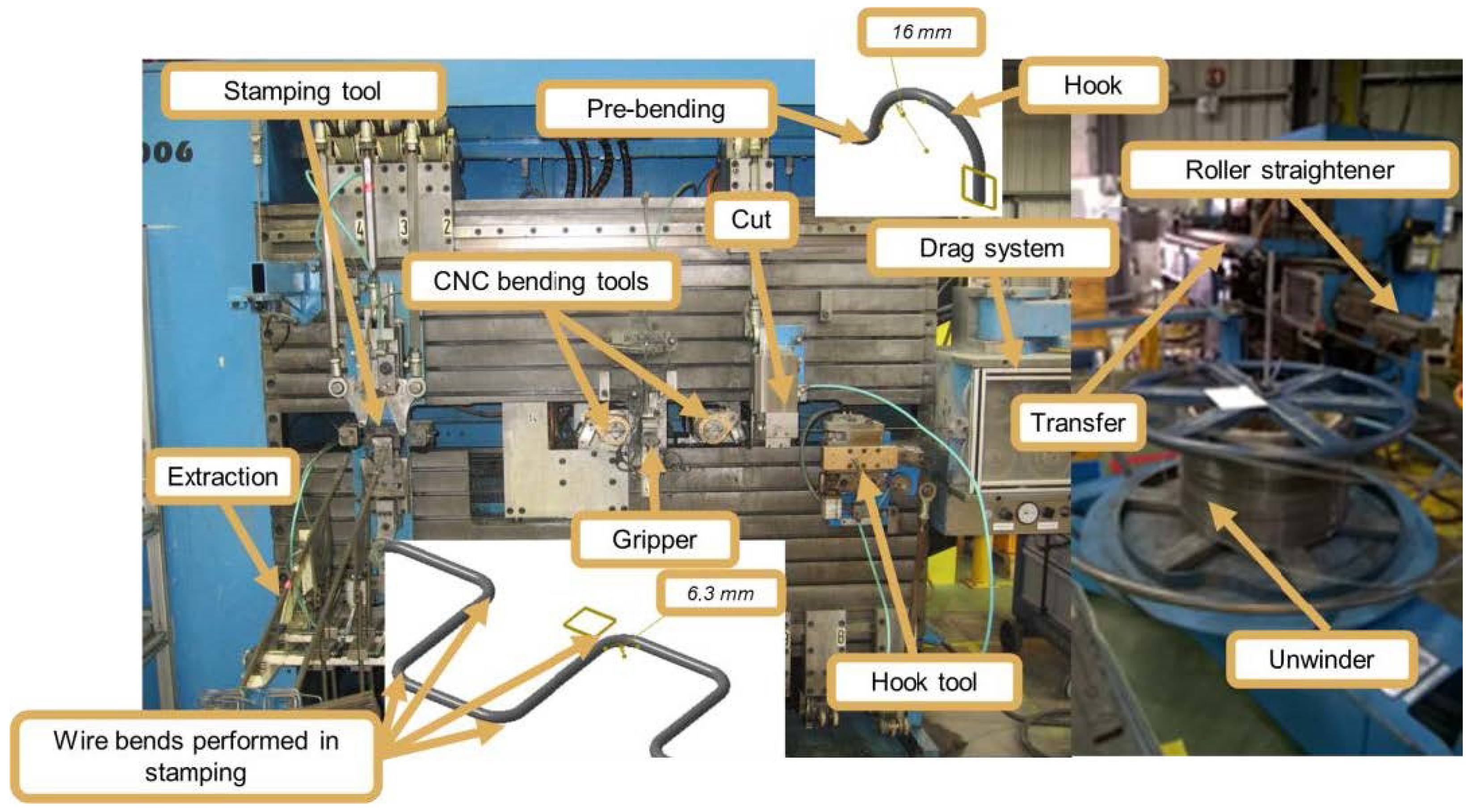
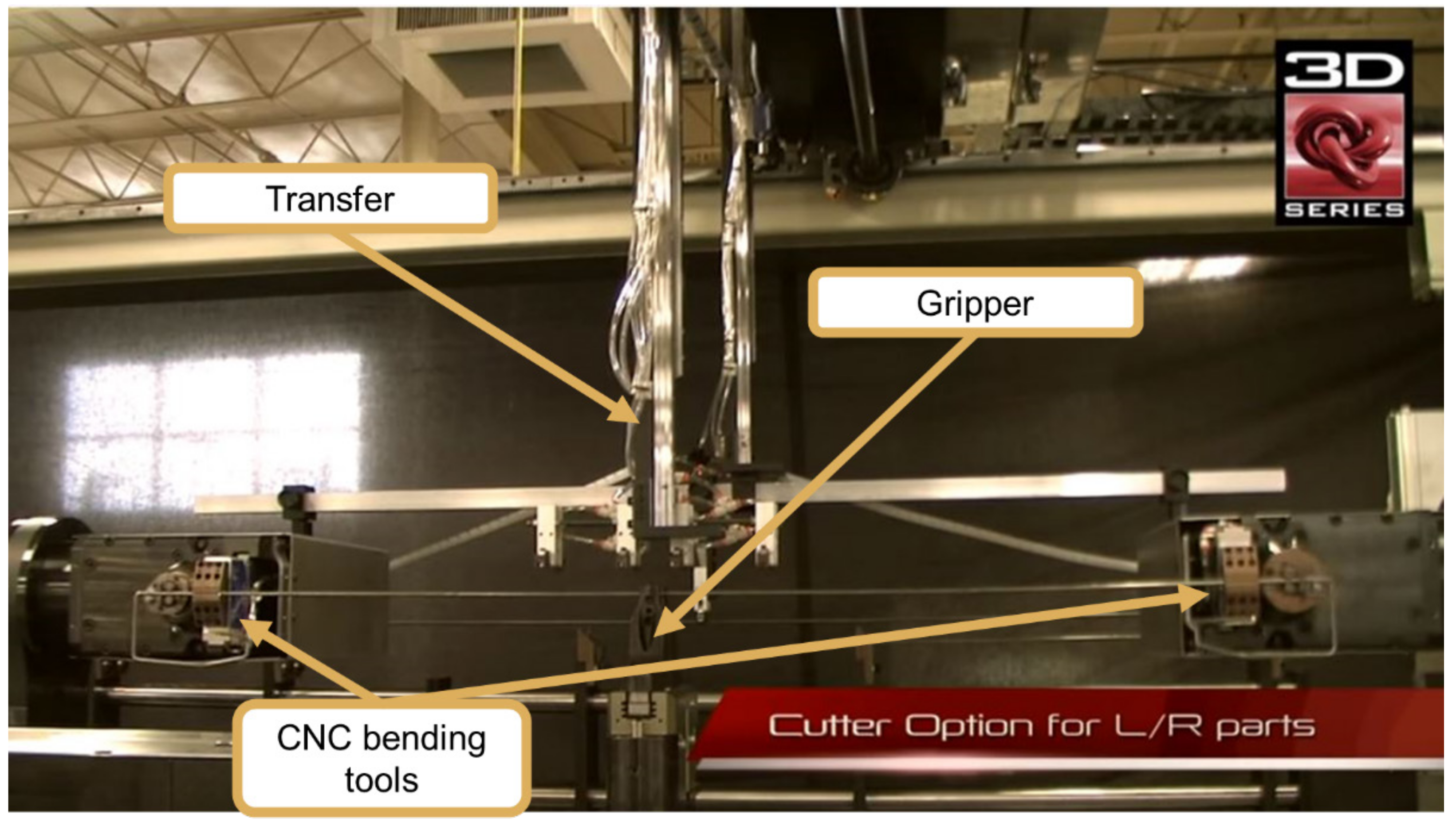
Wire-bending machines equipped with two CNC heads (Latour brand type) (
Figure 4) maintain some of the sequence described in the previous example: unwinder, straightener and drag system. However, after dragging, the machine has a folding device that makes the hook and pre-folding (folds that most cushions need to have). Immediately afterwards, the cutting device is located, which is only actuated after the wire is in the CNC bending heads. Finally, the wire is transported by a transfer system to a stamping tool, where the wire is finished.
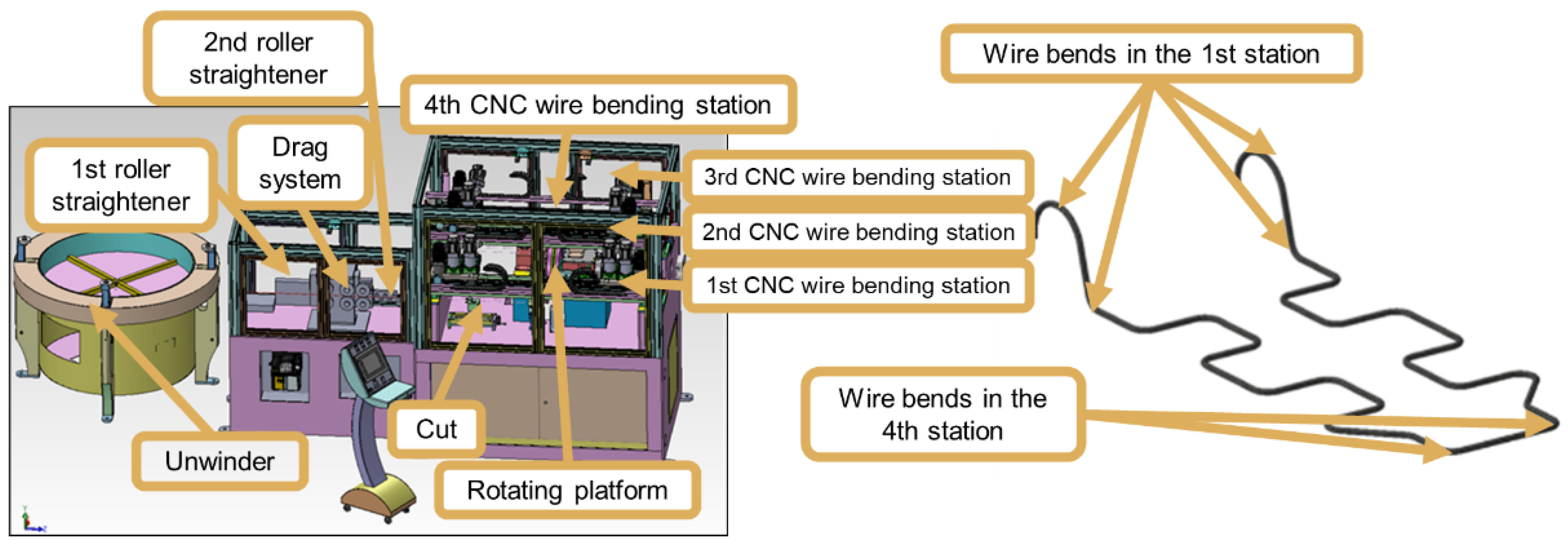
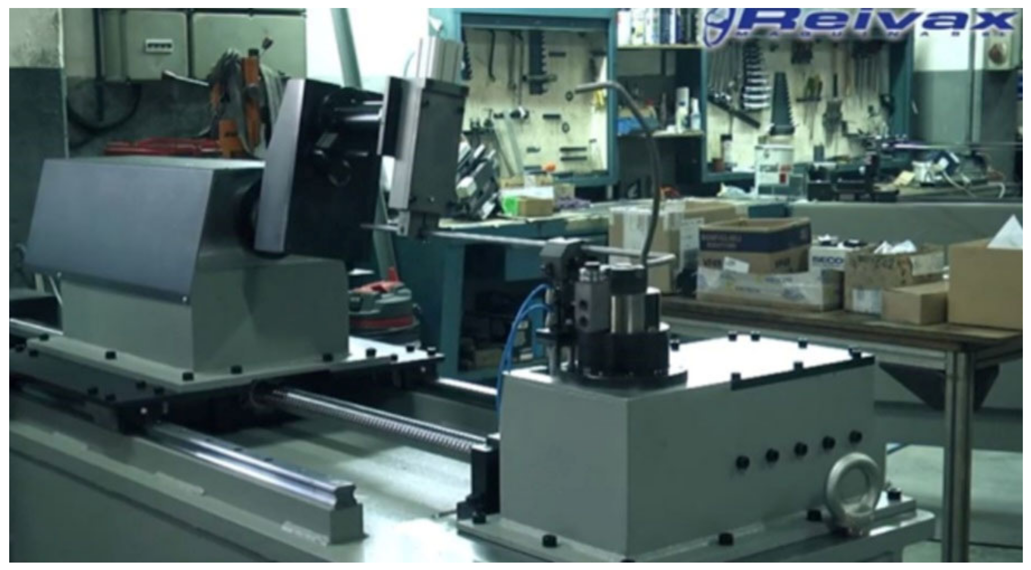
There are also specific machines for bending wires, mainly for U-shaped bending (Inovmaq brand, for example), as shown in
Figure 5. In this machine, the unwinder is not motorized, unlike the previous ones. After the unwinder, there is a two-plane roll straightener, a drag system with an encoder, a roll straightener, and a cutting device. After cutting, the wire is held by one of eight grippers that are on a rotating plate. The rotating plate moves the wire to the CNC bending stations, where the wire is formed. There are normally four CNC wire-bending stations, with the first station responsible for making the hooks and pre-bends and the last station responsible for making the two central bends.
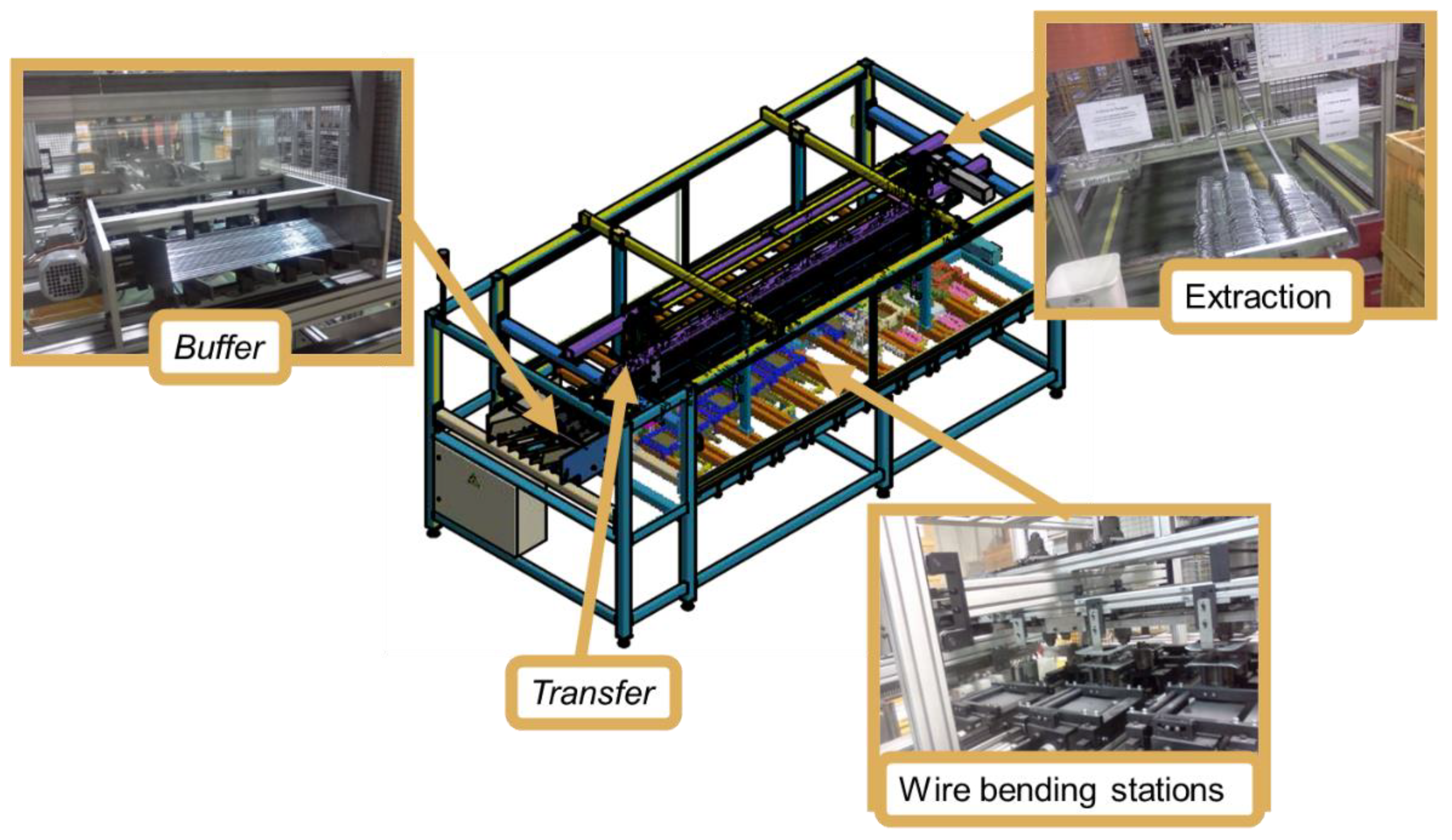
There are also specific wire-bending machines equipped with a transfer system (TEC, for example) shown in
Figure 6, in which the wire placed in the buffer is supplied to the transfer clamps. On average, each rig has twenty clamps. The transfer, in its work cycle, places the wire at the bending stations and, on average, each machine has twenty of these stations. The bending stations have the particularity of being actuated by pneumatic cylinders, the adjustment of the bends being carried out by mechanical end-of-course stops.
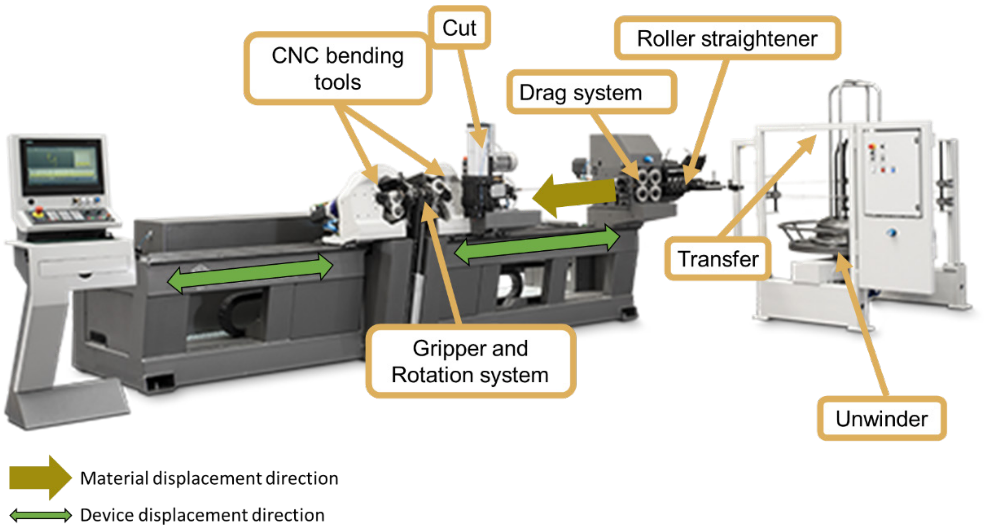
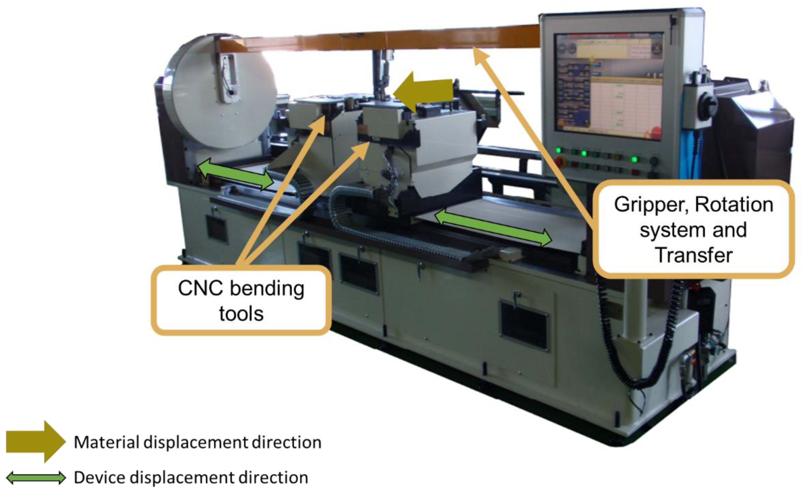
In the DH4012 VGP (BLM Group, Cantù, Italy) type bending equipment shown in
Figure 7, the wire is used in a coil. The equipment consists of a roller straightener, a drag system, a CNC cutting system, two CNC bending heads and a rotating central gripper.
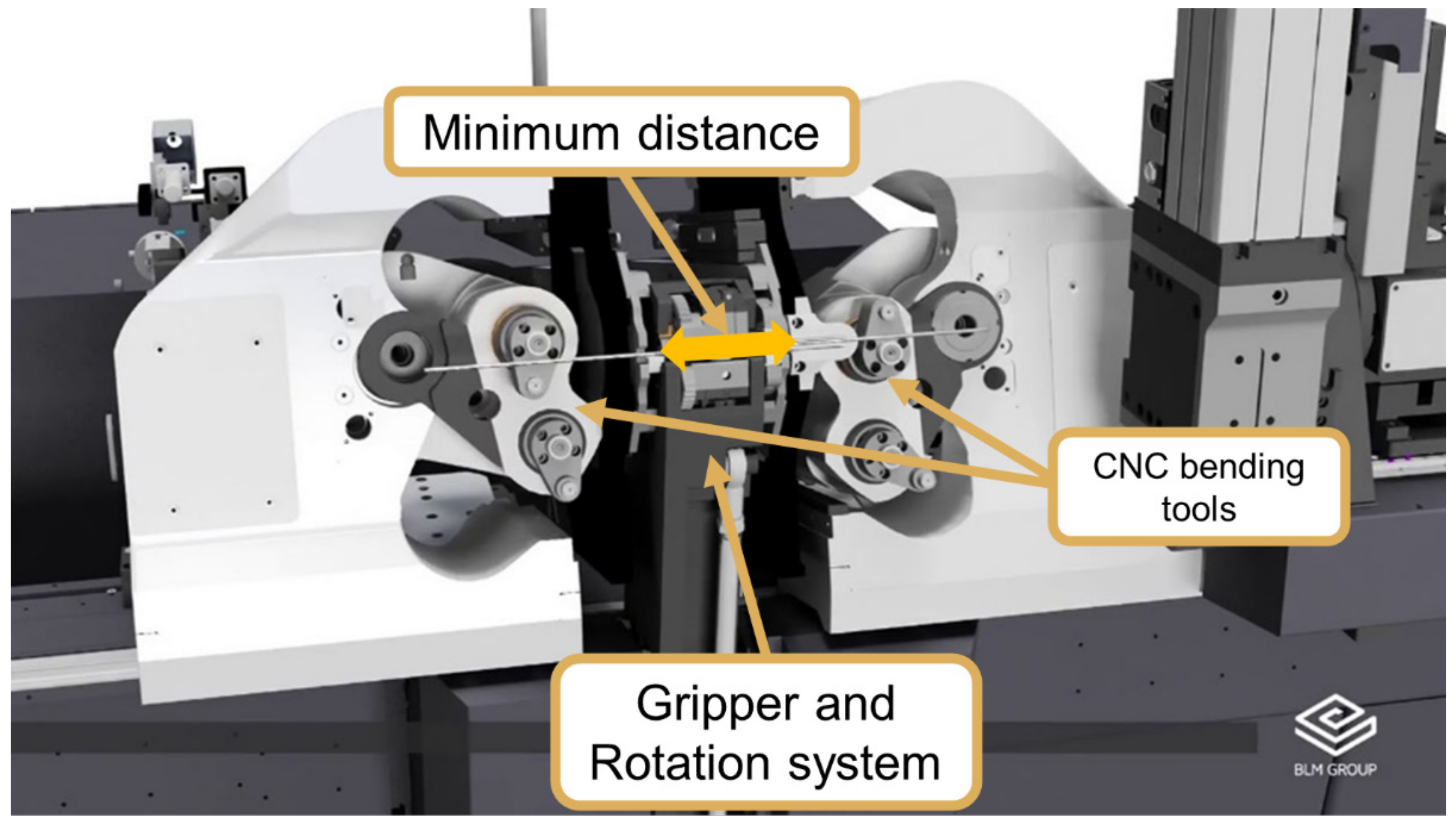
The rotary gripper makes it possible to perform the different wire planes that need to be produced.
Figure 8 details the configuration of the gripper with the bending heads. As the gripper is quite wide, it limits the central dimensions of the wire. This one has upward and downward vertical movement. When the gripper descends, it allows the bending heads to move closer together and shortens the central dimensions. However, in order to keep the wire fixed, these have clamps that are activated when the gripper is lowered.
In the TWF-C07AD bending equipment shown in
Figure 9, the concept is similar to the previous one, but wire fixation is promoted by a clamp provided with rotation movement. The system has two rotation axes, both with support at both ends of the machine. One has the center of the bending tools as a reference, while the other supports the gripper at the end in order to be able to supply and extract the wire.
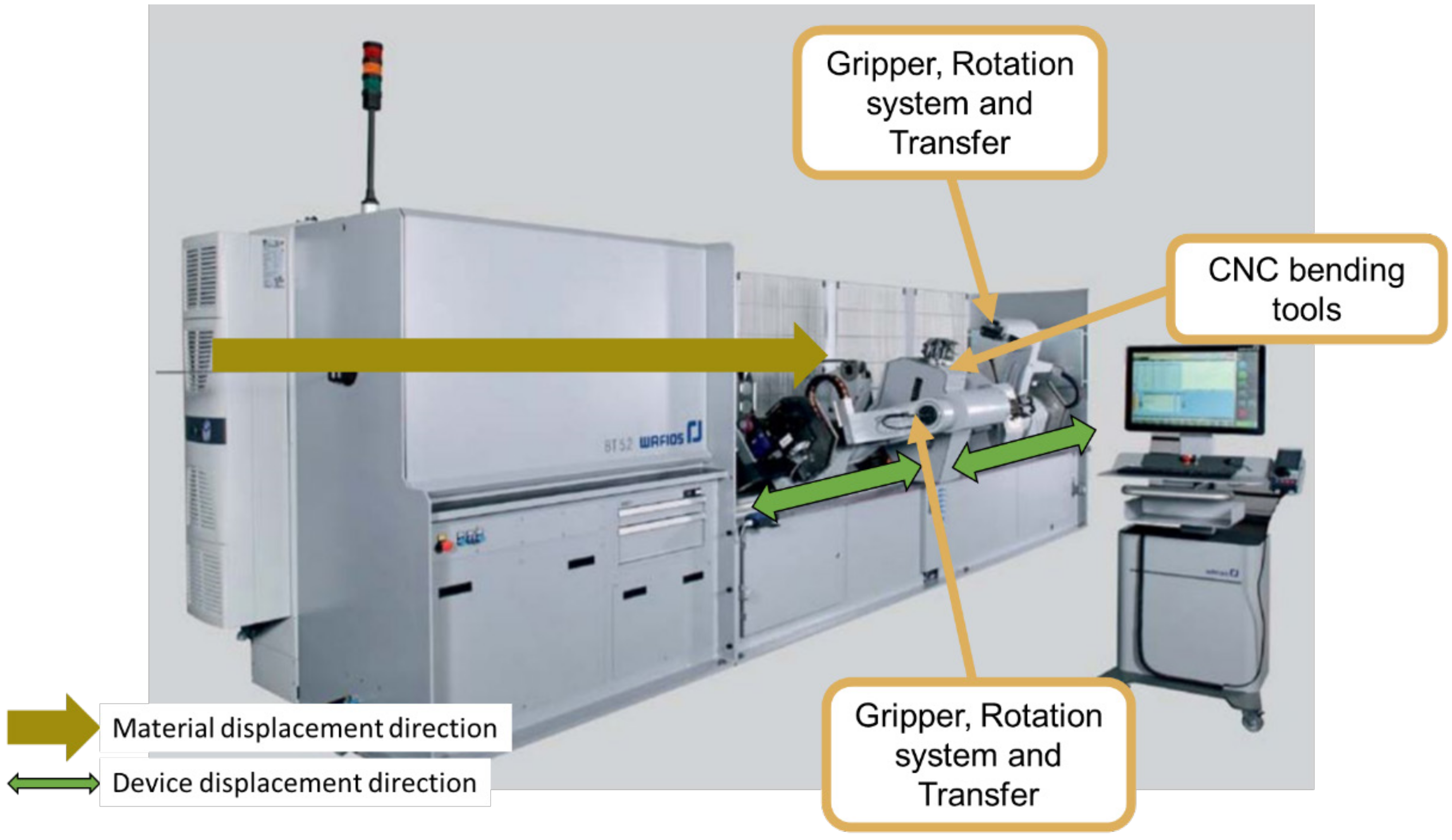
The BT5.2 bending equipment shown in
Figure 10 presents a different approach. In this equipment, the bending heads are fixed, which is done in two different bending axes. The manipulators can move in X to change the folding position. In addition to this movement, they have two more rotation axes, one on the bending tool axis and another on the bottom to move between bending, feeding and extraction stations.
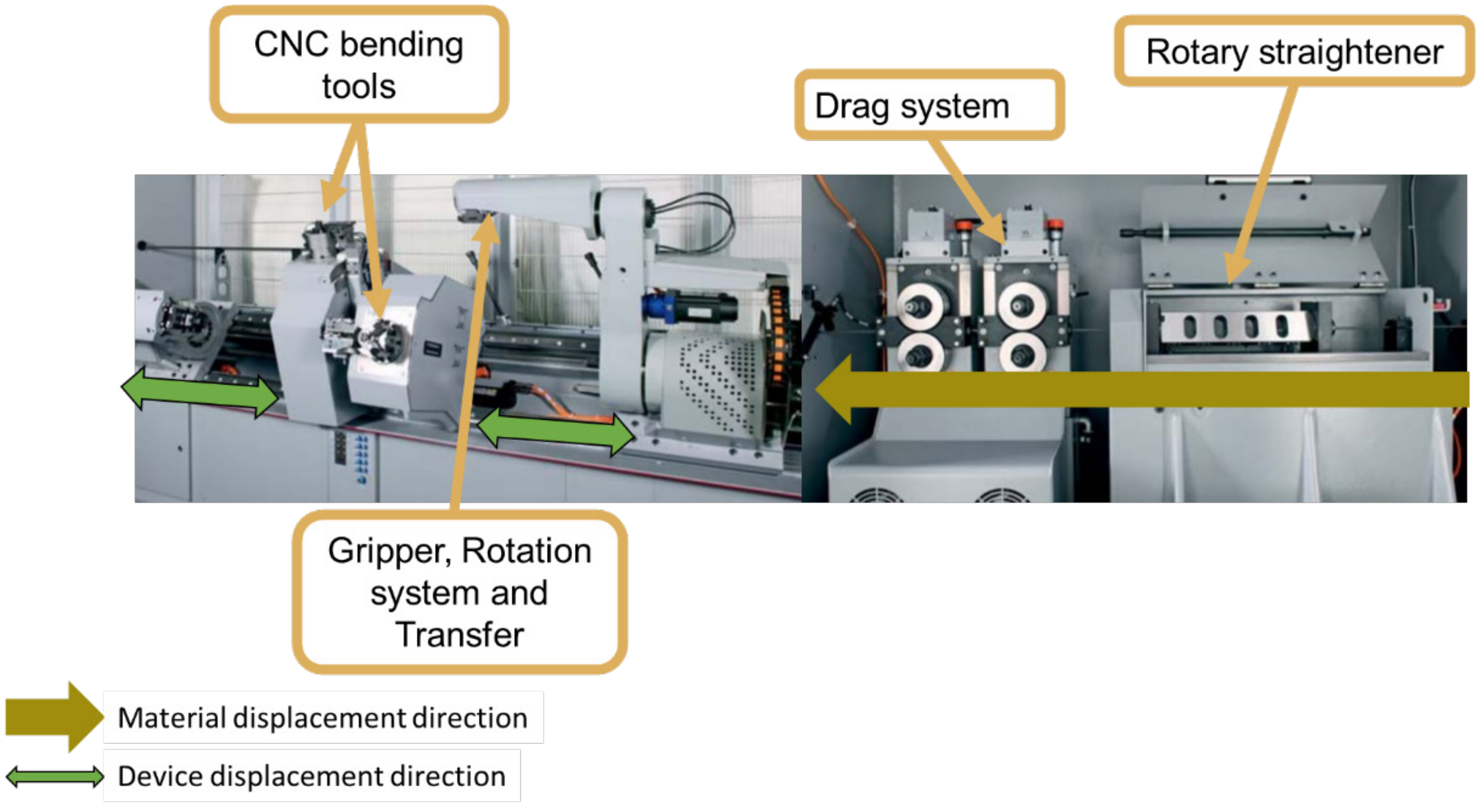
The BT5.2 equipment has a rotary straightener, whose approach is also different in relation to the previous ones, as can be seen in
Figure 11. As it has two bending stations on different axes, the wire is forced to be fixed alternately by each one of the handlers. The manipulators have clamping systems, as well as folding stations, to ensure better transition between stations.
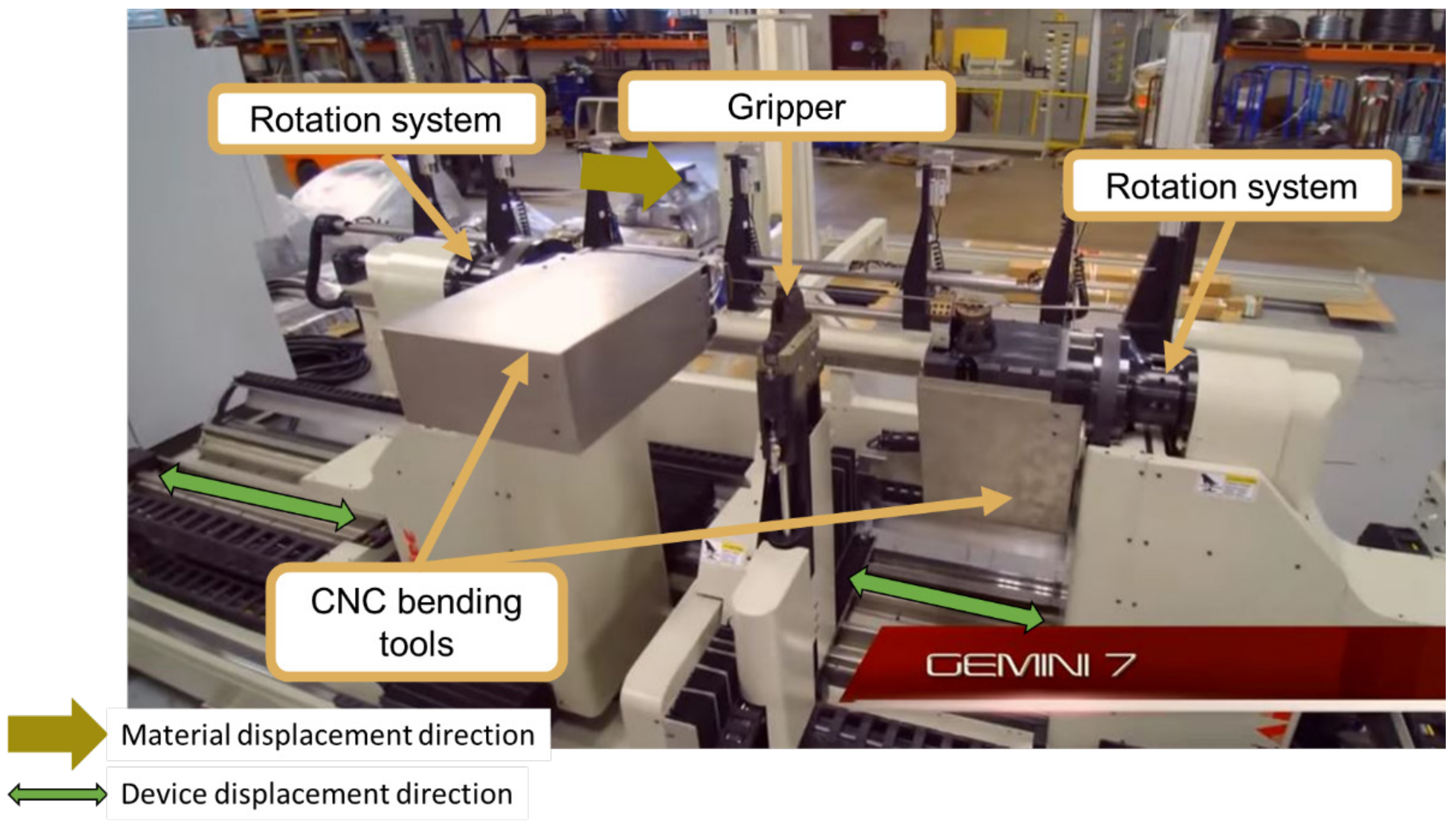
The Gemini 7 equipment shown in
Figure 12 has a central clamping system, and the bending heads rotate around the bending axis and move along the X axis, making the equipment more versatile.
The positioning and extraction of the wire are performed through two upper transfers, as can be seen in
Figure 13. It has independent movement, thus not limiting the movement of the bending heads.
The 3D-CN-8-M bending equipment shown in
Figure 14 presents a different concept, in which the bending head is fixed and the manipulator is responsible for the displacement in X. However, it presents the particularity of having only a rotation axis in the manipulator and a very compact clamping system.
Table 1 intends to summarize the main characteristics of the different concepts previously described in the perspective of the top management of any company. Thus, the main characteristics evaluated are flexibility, productivity and cost. This table does not intend to serve as a reference to further purchase decisions; thus, it is qualitative. Moreover, only some specific technical aspects are important to take them into consideration during the development of a new concept, taking the best ideas and trying to find solutions to overcome other ideas that do not work as well as expected regarding the requirements initially proposed.
Through a summary description of the main characteristics of the equipment already on the market, it can be inferred that they have very particular advantages. However, they also have some limitations that are restrictive to combining a very high productive capacity and sufficient flexibility, in the same equipment, for any company to be able to easily change the type of wire produced without significantly interfering with its productivity, which would have obvious implications for the competitiveness of the manufactured products. This justifies the need to create a new equipment concept capable of combining flexibility with high productivity.
3. Methodology: Drawing the Formability Concept
The suspension system of a vehicle seat (
Figure 15) has foam and flexible structures in wire following a spring shape, which have the capacity to filter vibrations. The level of vibration isolation varies depending on the type of vehicle. In sports cars, drivers seek to have a more direct connection with the car, with the aim of feeling the sensations that the car transmits better. As a result, more rigid seats are designed, that is, with a lower damping rate. Luxury cars have exactly the opposite requirements in that, in addition to elementary suspension systems, they have additional systems that allow adaptation to different occupants [
52].
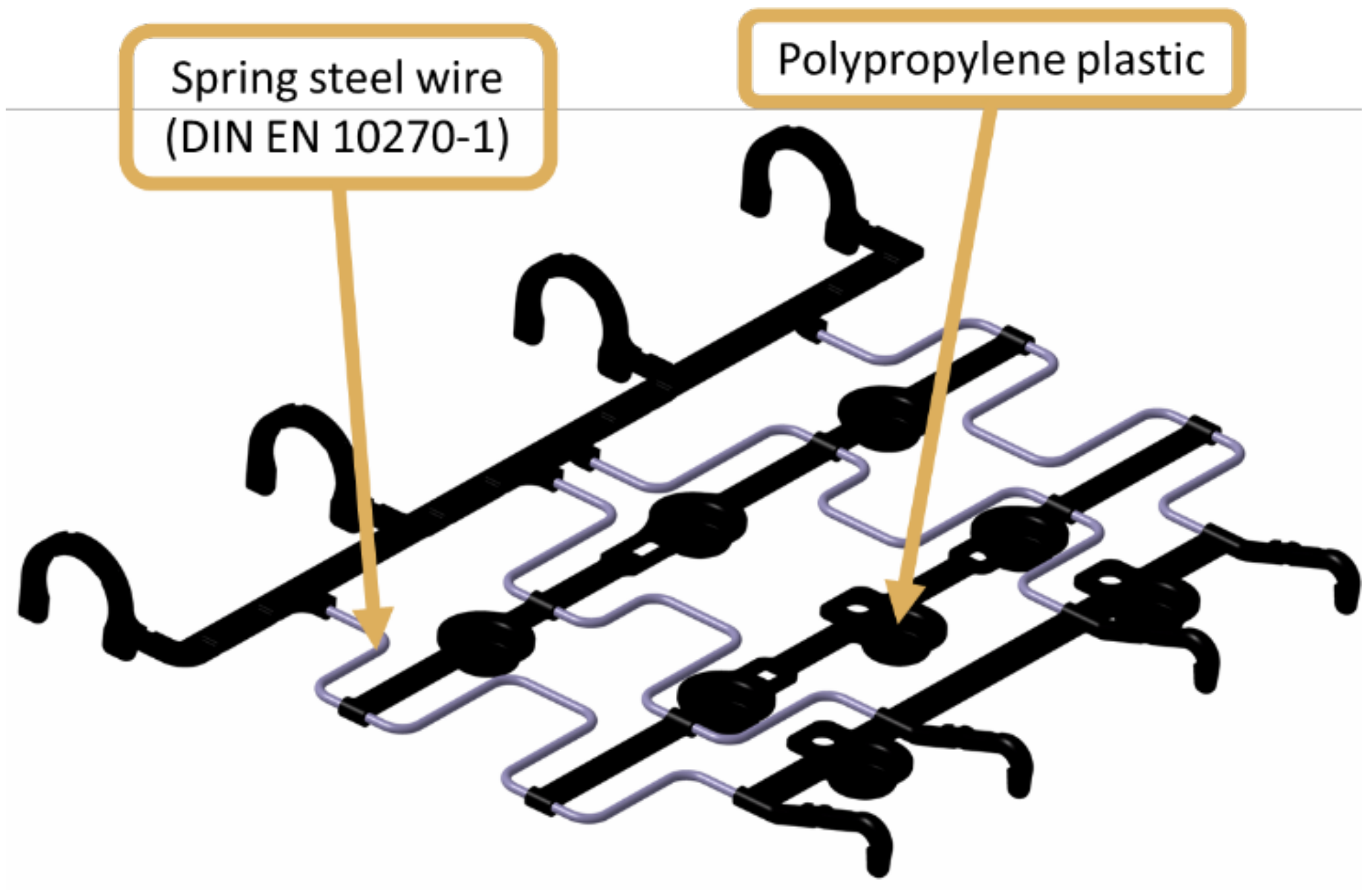
Taking into account the components of the suspension system of a vehicle seat, in
Figure 2, the marked component is the one that corresponds to the scope of this work. This is the cushion (also pointed out in
Figure 1), which is conceived from the over-injection of plastic in previously formed wires. The plastic used is usually polypropylene and the wire is made from spring steel.
In the process of folding the cushions, as well as the suspension mats whose structure is very similar, equipment existing until now had a significant gap as the most flexible ones have low productivity, not being indicated for projects with a large production volume. On the other hand, there is also equipment that shows high productivity but is not flexible. Being more suitable for large-volume projects, that is, they follow the principle of fixed automation. For this reason, the modification of high-productivity equipment for new projects entails high costs, which customers are increasingly unwilling to pay, affecting the competitiveness of companies in the field.
In order to make the equipment more flexible, and after the wire class has been established, it is necessary to identify and characterize the wires produced. To this end, a survey about the following features of the wires needs to be performed:
Wire diameter;
Number of folds;
Number of different radii per wire;
Number of bending planes per wire;
Wire length;
Number of hooks;
Minimum radius able to avoid crack induction on the wires.
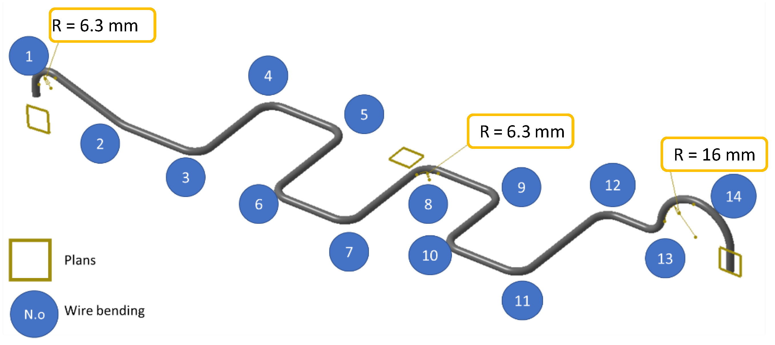
A typical wire used in cushions is shown in
Figure 16, which can be used as an example for the development of the concept. In this cushion, four wire references are used, in which the wire diameter is 3.4 mm, the wire class is SH (high tensile strength, following the EN 10270-1 standard), it has fourteen bends, two different radii, three planes of folding, two hooks and is 583 mm in length. The references are two symmetrical pairs.
In
Figure 16, folds 1 and 14 are commonly referred to as hooks, and at a minimum, each pad has a hook. Based on a company producing this type of components for seats of motor vehicles, a typification study of its main characteristics was carried out to guide the design of the new equipment.
Table 2 shows a summary from which it can be concluded that the wire diameter varies between 3 and 4 mm, the number of bending planes varies between two and five, the number of hooks varies between one and two, the number of radii used in each wire cushion range varies between two and four, the length of the wire fluctuates between 400 mm and 1120 mm, the number of bends varies from thirteen to twenty-five and the wire grade is SH or SM.
4. The New Concept
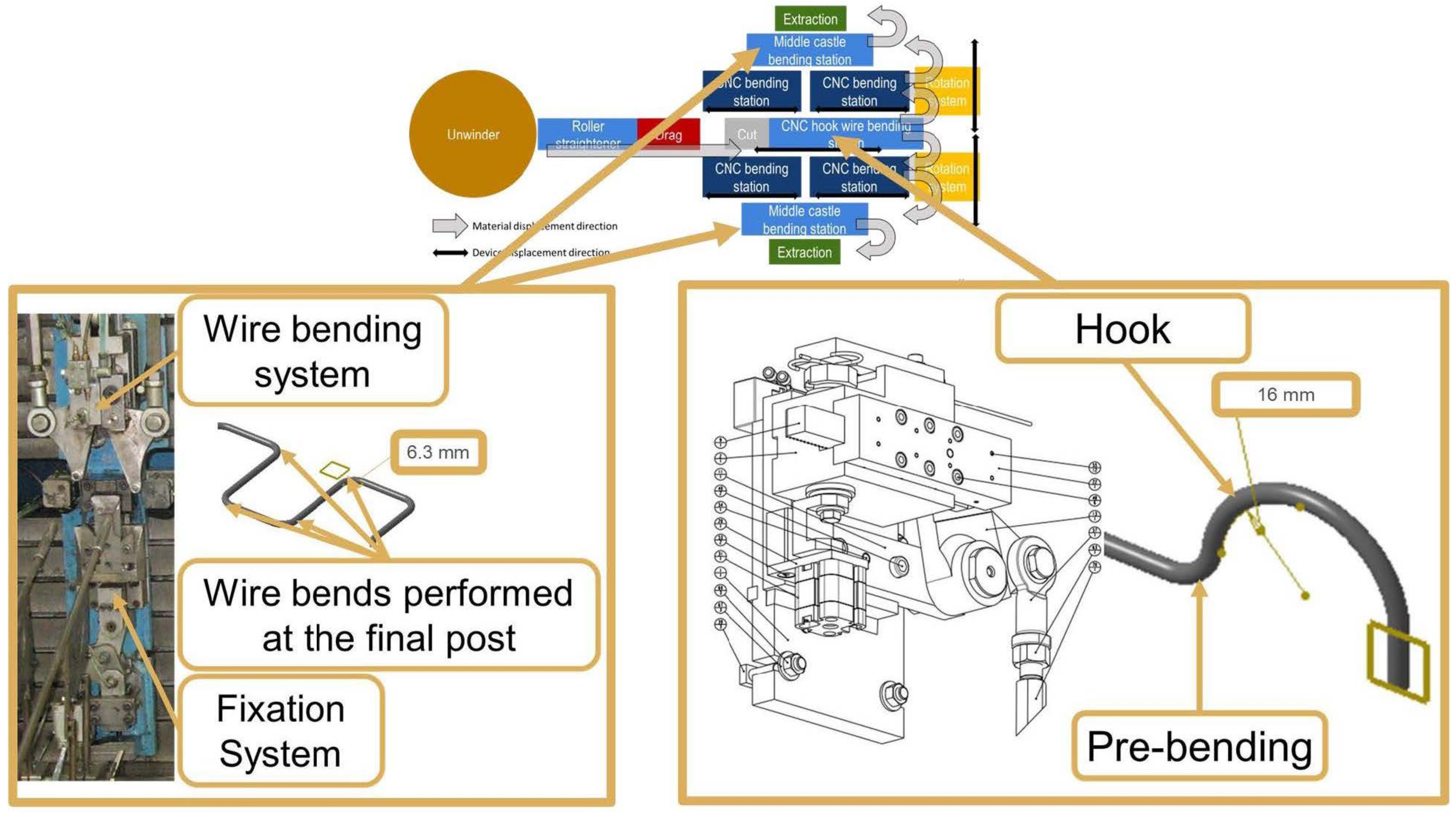
Thus, a new equipment concept was conceived and designed using Catia V6 software (Dassault Systèmes), which is schematically represented in
Figure 17. In this new concept, it was understood that the wire was pulled by the drag system, being subsequently taken to the straight position through a two-plane roller straightener. After dragging, the wire is cut by the cutting device, which has movement capacity to perform various cut lengths, thus meeting the intended flexibility requirement. The wire piece is fixed in a system of clamps, ready to be picked up by the manipulator. The manipulator, in addition to transporting the wire between stations, has a rotation system, which yields several planes in the wire-bending process. The manipulator will take the wire to the cutting system, moving it to the CNC bending stations and to the final bending stations. For increased cadence, the center post has a hook fold and pre-fold station, similar to what Latour equipment uses. After the CNC folding stations, it has a folding station that makes the last two central folds. It is similar to the last station usually used by Latour and Inovmaq (
Figure 17).
What makes this concept more innovative are the stations used to make the hooks and the final folds, as shown in
Figure 18. The station used to make the hook, in addition to allowing the overlapping of operations as allowed by the Latour concept, also increases flexibility as its position is given by a servomotor, together with the cutting device.
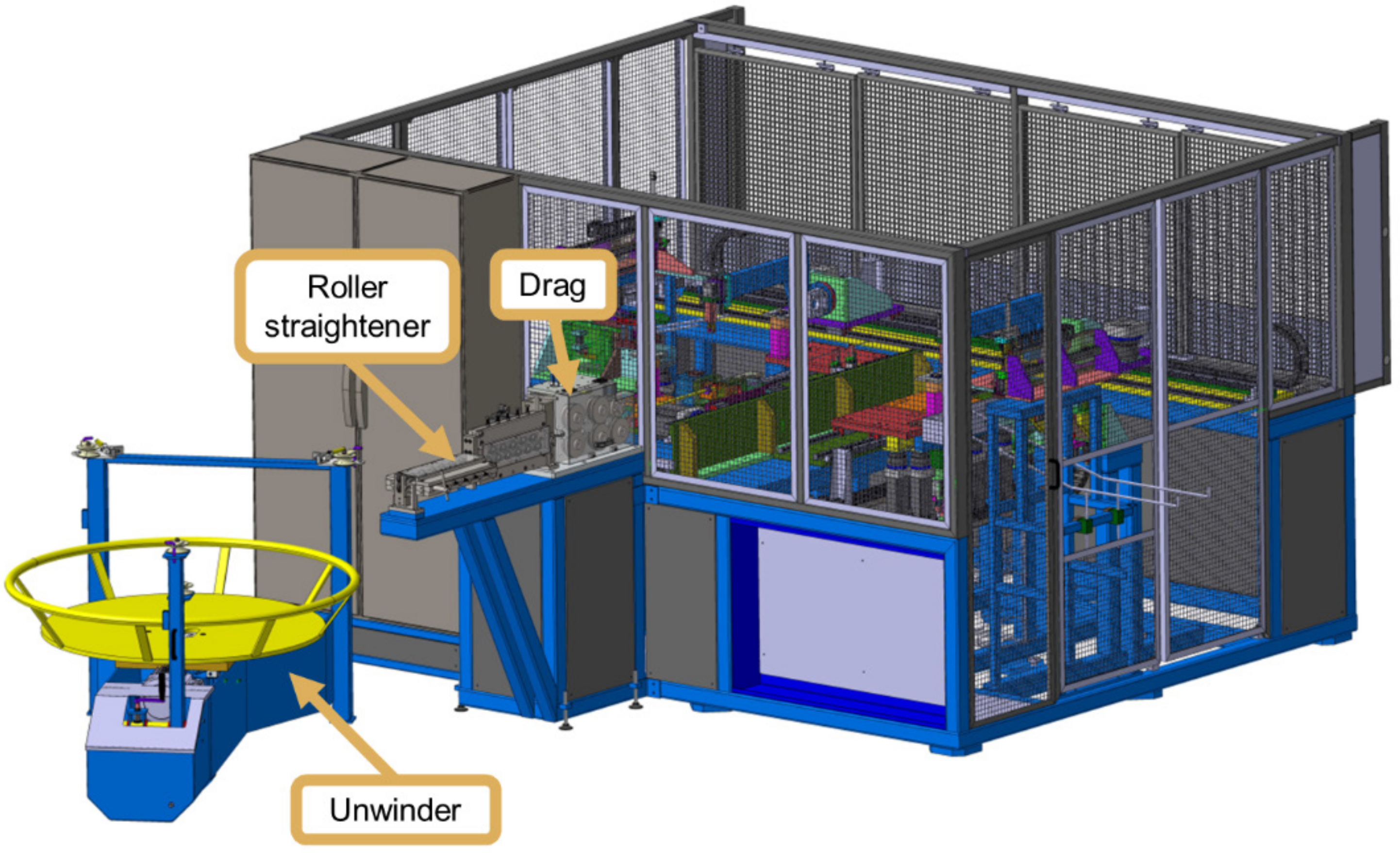
Like most of the concepts already presented, this equipment has an unwinder, roll straightener and drag, as can be seen in
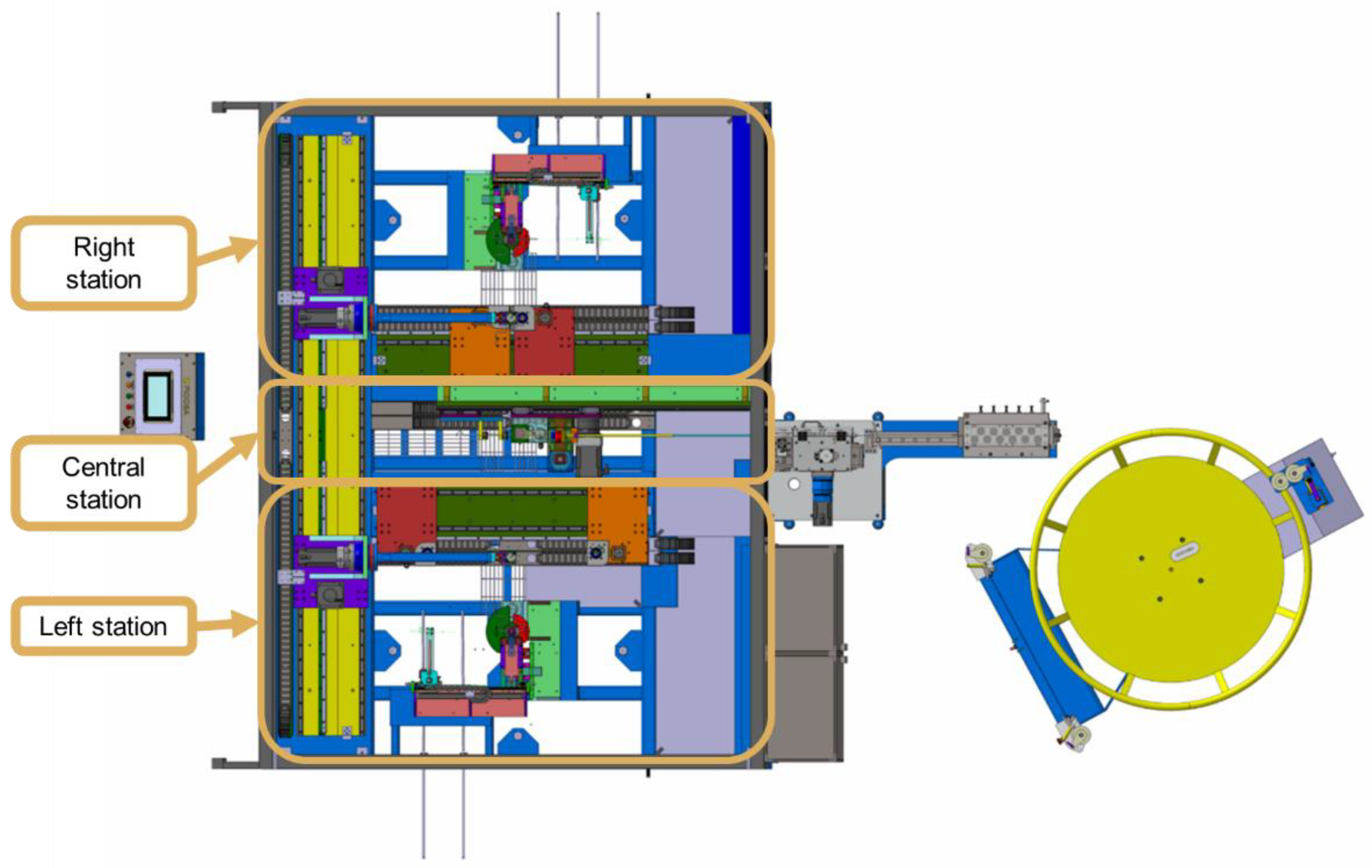
Figure 19. In this concept, the equipment can be divided into three large groups of subsets, as it is possible to observe in
Figure 20. These groups are the following:
Central post;
Left post;
Right post.
At the central station, which can be seen in
Figure 21, the raw material is fed into coils, thus avoiding the use of cutting equipment and the existence of intermediate stocks, as in the TEC concept (
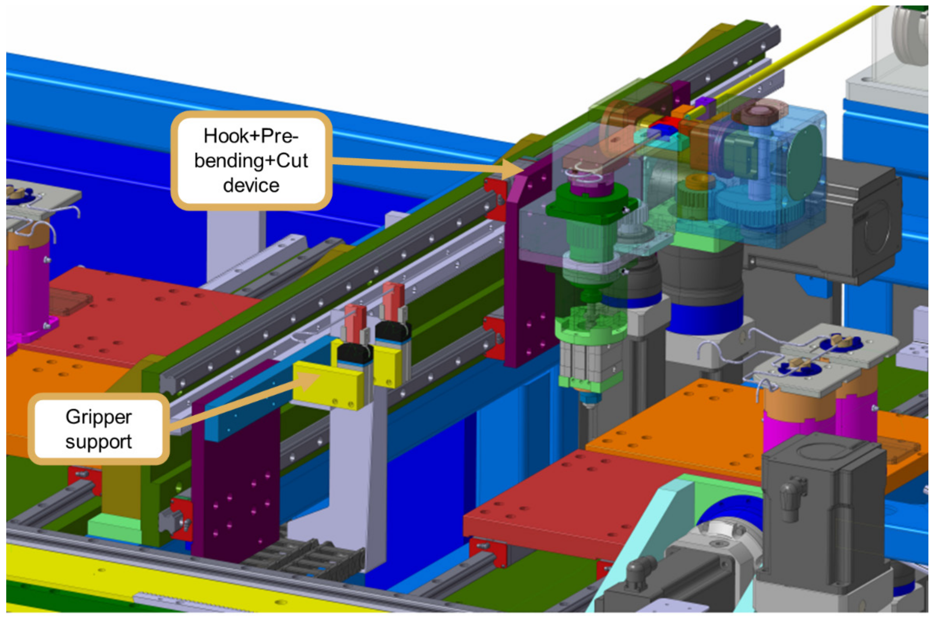
Figure 8). At the central station, the coil is placed in the unwinder where it is unwound, maintaining constant tension. The wire is pulled by the drag system, forcing it to unwind and straighten. Wire alignment is carried out when passing through the two-plane roller straightener. After dragging, the wire passes through the cutting system and reaches the hook tool, where hook bending and pre-bending takes place. With these operations carried out, more wire is fed until it reaches its cutting position. Once in the cutting position, the support claws are activated, and then the cut is performed. Finally, the device that performs the Hook + Pre-bend + Cut set withdraws, and the wire is available for the subsequent operations. The devices that make up the central station are as follows:
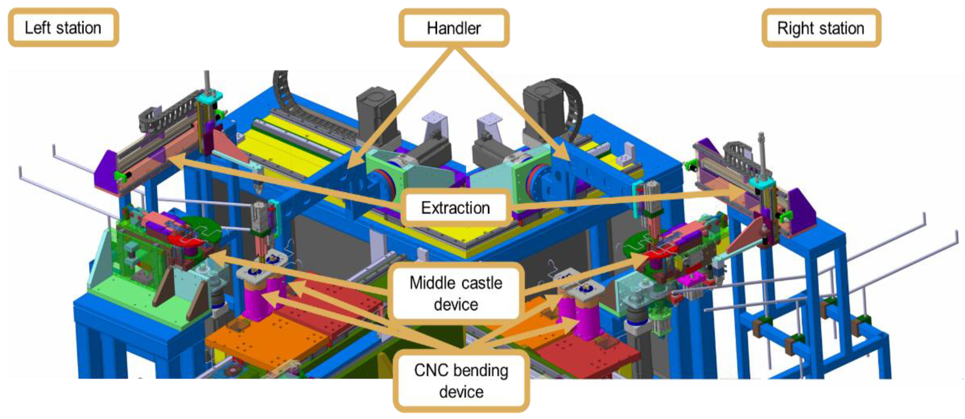
The wire available at the central station is picked up by the left or right handler (
Figure 22). Afterwards, it moves to the CNC bending devices. Here, several bends are performed, always with the wire fixed to the manipulator. With the bends completed, it moves to the middle fixation device. The wire is fixed in this device and the central bends of the wire are performed. Finally, the extraction system removes the shaped wire and drop-off it onto the equipment’s exit ramps.
The devices that make up the left and right stations are as follows:
CNC bending device;
Middle fixing device;
Handler;
Extraction.
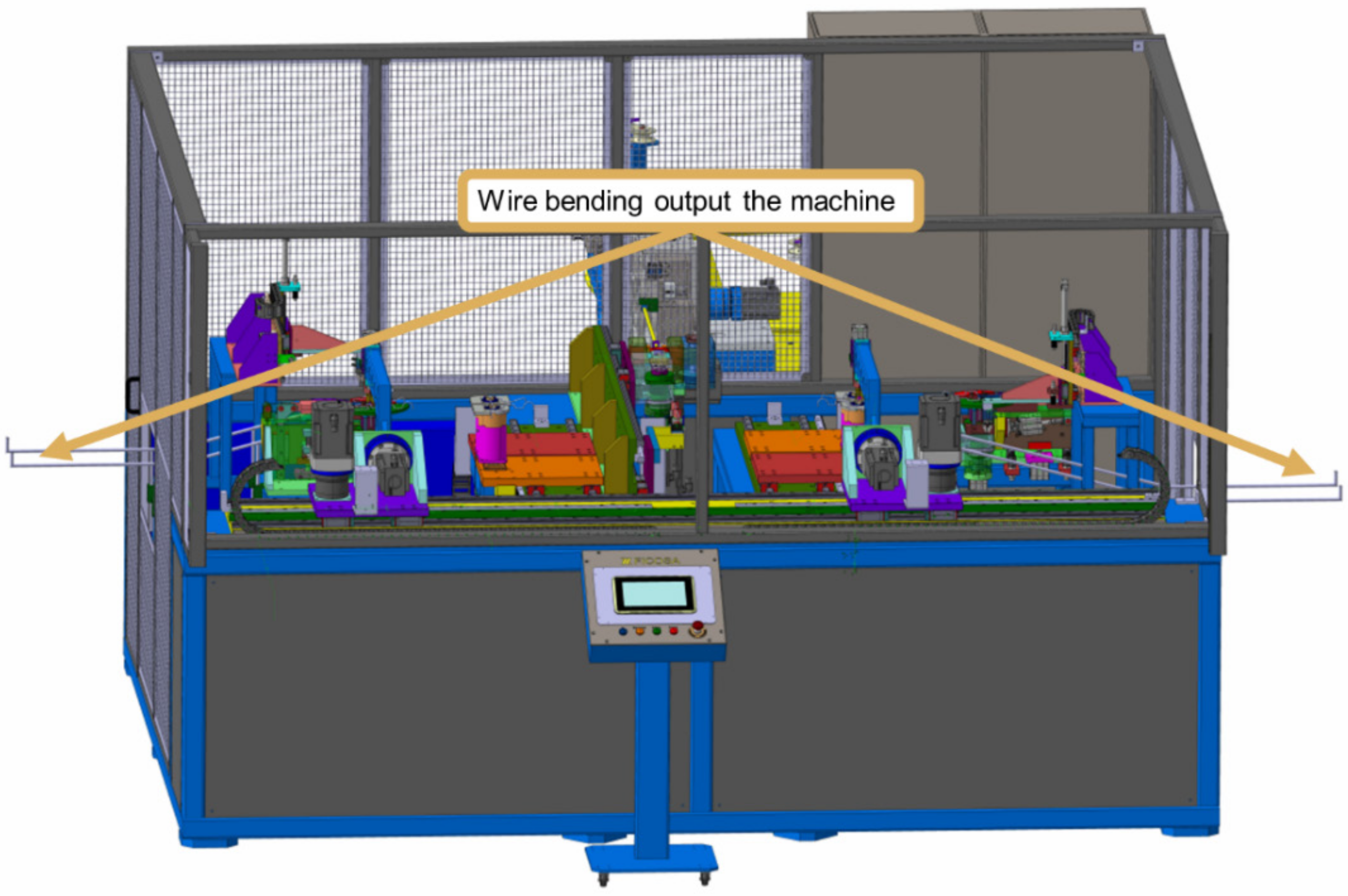
The equipment is capable of bending wire from 3 to 4 mm, with a maximum length of 1100 mm. The wire is dispensed on both sides of the equipment, as shown in
Figure 23.
In terms of productivity, and considering only five of several references produced by the company used as target for the implementation of this concept and considering the concept now developed face to face with the TEC and the Robomac concepts previously described, a comparative study is presented in
Table 3, yielding an understanding of the differences.
In addition to productivity gains, this concept yields the implementation of new wire references, changing only the tool kit, as can be seen from the different references already implemented. Therefore, this concept is proven to be much more flexible and productive than any of the concepts already existing on the market. The flexibility of this concept is also verified in the ability to produce two symmetrical references simultaneously, or even different references on each side of the equipment, a situation that is also innovative, as there is currently no equipment that uses this concept and is capable of allowing different programming for each side of the machine. This point is extremely important for the manufacture of bent wires for car seats, as it is extremely common for each component on one side to have a corresponding one on the other side (symmetrical). However, in certain situations, there are differences in detail (no symmetry), which can be easily managed by this new equipment, producing equivalent parts, although with specific formats. This possibility significantly facilitates the management of stocks and setups, as production is flexible, allowing the perfect adjustment of the quantity to be produced to the quantity ordered by the customer and, when it comes to symmetrical components, the quantity obtained from one side of the equipment is exactly equal to that obtained from the other (imposed by the cadence of the equipment), which makes it possible to complete the amount of shaped wires necessary so that the cushions or suspension mats can be produced immediately (the next product where the bent wires are applied), with a shorter lead time. Thus, the advantages presented by this innovative concept are clear, both in terms of productivity and flexibility, as well as the advantages in terms of internal logistics that it provides.
The cost of this new concept is 3% lower than that of the TEC concept because the last one uses a high number of mechanical parts. Taking into account the Robomac concept, it is 19% higher. However, the productivity gain is around 230%, largely offsetting any disadvantage in the initial investment. With regard to the necessary investment in tools, there are significant differences in terms of their cost. The cost of the tools for the new equipment is about the double that of the Robomac tools cost, which is compensated by increased productivity. On the other hand, the tools of the new concept are 87% lower than the cost of new tools for the TEC concept. It is easy to understand that, although some differences exist, the increased productivity provided by the new concept overlaps the small costs of the tools and allows a flexibility level completely incomparably higher.
5. Discussion
This work was developed with the aim of solving the need for concrete of companies that produce components for car seats, whose products have a relatively low added value, and where any increase in productivity without deteriorating the quality is extremely welcome. Analyzing existing equipment on the market (benchmarking), it was possible to detect an opportunity to develop a new concept that would significantly increase productivity, without jeopardizing flexibility. The concept aims to take advantage of the dead time that the wire feeding system has in relation to bending systems, which are necessarily slower. A concept was then conceived that aimed to achieve double production, doubling the bending systems around a common wire feeding system.
Given that vehicle customization led to an increase in the model variants available to customers, setup time has become a problem that needs to be resolved quickly as tool changes and process fine-tuning heavily penalizes productivity [
13]. It also became necessary to create an agile system for changing tools, which were not excessively expensive, but which fully complied with what was intended, i.e., to switch production from one model to another in an extremely expeditious manner [
14,
15,
16].
In addition to this, it was possible to establish two ways in the same equipment, programmable in a different way, which allow two different references or mirrored references, to be carried out simultaneously. In terms of bending-wire operations with this complexity, this is a novel concept.
In addition to extremely significant gains in terms of productivity and flexibility, it was also found that, in terms of internal logistics, there are significant advantages. In fact, two symmetrical models can be produced simultaneously, producing exactly the same amount of both products at the same time, which allows these wires to move simultaneously to the next production step (manufacturing cushions or suspension mats) simultaneously, which allows a much more organized production management. In case there is a need to produce different products, lead time is also greatly reduced, as it is not necessary to finish the production of a model to start the production of another. Thus, industrial management is much more agile, allowing different combinations of products as necessary to respond to demand.
Thus, it can be said that this work is in line with some work that has already been carried out in this area [
7,
33,
34,
52], where an attempt was made to increase productivity, also significantly improving the logistics around these processes that normally have low added value. Management techniques, in many cases, solve serious problems in terms of lack of competitiveness in products of this nature [
16,
36,
37], but sometimes it is even necessary to promote necessary changes in terms of the equipment involved. Automation plays an extremely relevant role in this regard, mainly flexible automation, but it is necessary to select the best set of devices so that the desired results can be obtained [
4]. In addition, a high critical state of mind is necessary, so that truly innovative solutions can be obtained, disruptive with what has been conducted so far, in order to achieve new standards of productivity and flexibility [
4,
19].
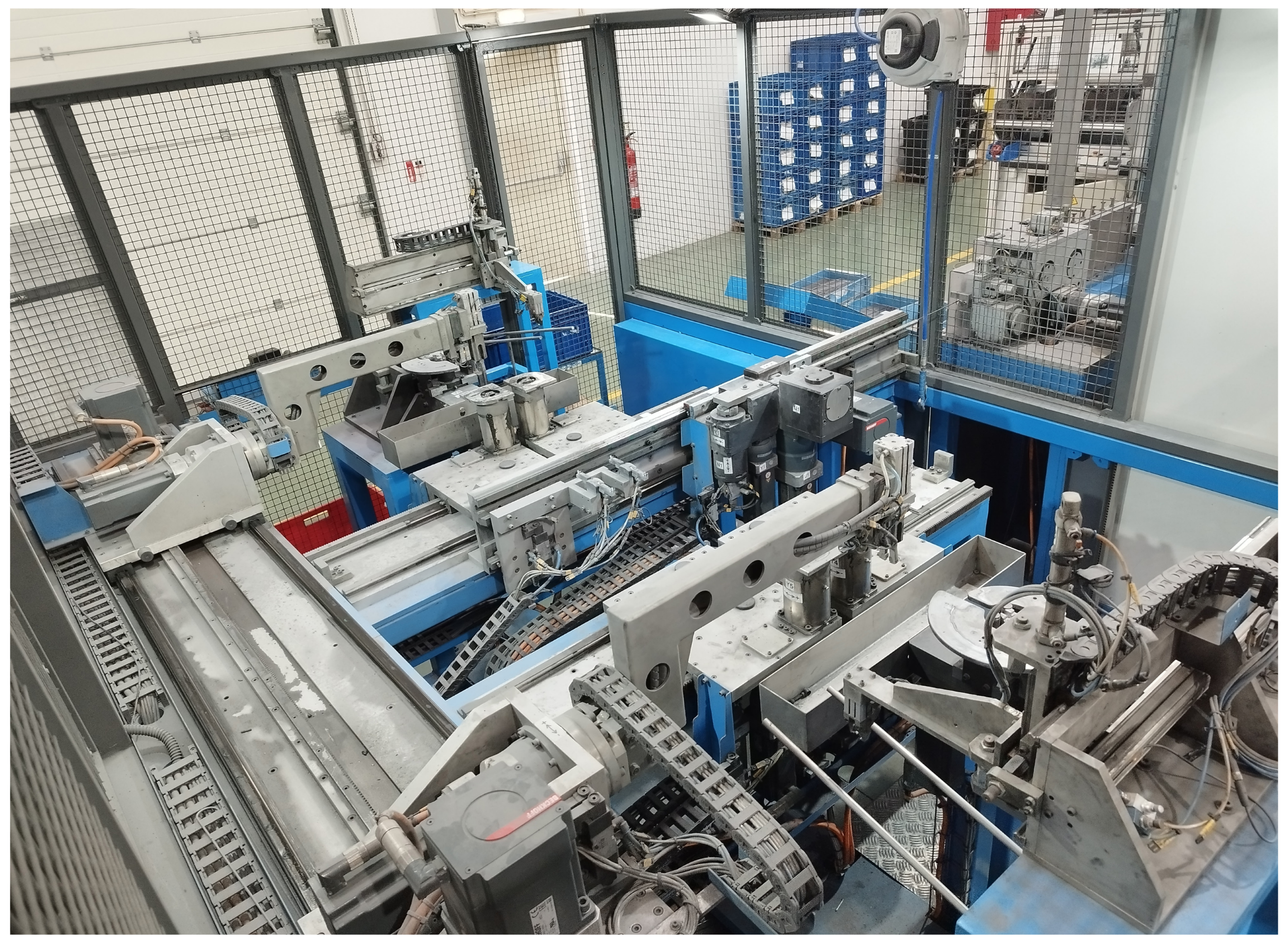
Figure 24 intends to illustrate the implementation of the previously described concept, which only became viable through a full demonstration of the advantages that it would entail for an increase in flexibility and productivity. The equipment is based on 1400 different parts and devices, comprising electrical actuators, pneumatic actuators, sensors, electrical components, standard parts and several mechanical parts specifically designed to this equipment, especially conceived to be easily replaced through planned maintenance operations.
6. Conclusions
Given the characteristics of the wires and the volumes of the projects, budgetary restrictions and production objectives are usually imposed. An innovative solution for wire-bending equipment is developed, requiring a low budget and complying with the requirements and constraints initially pointed out. The concept consists of equipment provided with three stations, a central one where the wire is unwound from the coil, straightened, shaped (double bends are made) and cut. In the lateral stations, left and right, the wire, after being picked up by the manipulator at the central station, is shaped in CNC bending devices with the wire always fixed in the manipulator. At the end, it is placed by the manipulator at the final bending station to finish shaping the wire. After forming, the wire is extracted onto material exit guides.
The implementation of this new concept yielded an output in productivity of around 230% in relation to flexible equipment previously existing, and a gain of 12.5% in relation to high-cadence equipment on the market. In addition to productivity gains, this concept yields the implementation of new wire references by changing only the tool kit. The flexibility of this concept is also verified in the ability to produce two symmetrical references simultaneously, or even different references (albeit similar). This point is extremely important in the management of stocks and setups.
The cost of this new concept is 3% lower than the TEC concept and 19% higher, relative to the Robomac concept, but with the previously described productivity gain.
The cost of new tools is double that of the Robomac concept, which is 87% cheaper than the cost of new tools for the TEC concept. It is thus verified that this concept is much more competitive in the implementation of new projects. The new concept was also thought to be easier to repair. Knowing the main drawbacks of the other equipment, some solutions were developed, taking into account forecasted problems. Moreover, because all development is made “in house” mode, the domain of all devices and mechanical parts are easier to deal with. A maintenance guide is provided to the maintenance department with all care needed in the different zones of the equipment, identifying and solving the most common problems.
Table 4 intends to summarize the main advantages and limitations of the developed concept.
This work followed the design search research methodology, taking solutions already implemented in the market as a starting point and promoting an evolution of knowledge from these initial ideas, reaching a level of knowledge that can be shared and expanded to other business areas, equally successfully. In fact, the knowledge produced can be used in other industries linked to the same sector, or even to different sectors, yielding the development of new concepts with greater efficiency. Indeed, the DSR methodology structured the thought and achieved the desired results, thus verifying that it is extremely useful in the study of upgrading production systems.


