Article

Wall Thickness Uniformity in ISF of Hydraulic Support: System Design, Finite Element Analysis and Experimental Verification

1
School of Mechanical and Precision Instrument Engineering, Xi’an University of Technology, Xi’an 710048, China
2
School of Mechanical and Material Engineering, Xi’an University, Xi’an 710065, China
*
Author to whom correspondence should be addressed.
Machines 2023, 11(3), 353; https://doi.org/10.3390/machines11030353
Submission received: 25 January 2023 / Revised: 25 February 2023 / Accepted: 1 March 2023 / Published: 4 March 2023
(This article belongs to the Section Advanced Manufacturing)

Abstract

:
Uniform wall thickness plays an essential role in avoiding forming failure in incremental sheet forming. However, it is challenging to promote the uniform distribution of wall thickness in single-pass forming of high wall angle and complex three-dimensional thin-walled parts using flexible dieless incremental sheet forming technology. In this article, based on the hydraulic support single-point incremental sheet forming technology, the finite element software is used to simulate and analyze the influence of different support pressure on the wall thickness distribution and the uniform critical angle of single-pass incremental sheet forming truncated pyramid parts. The results show that the hydraulic support can effectively improve the thickness uniformity and critical forming angle. In addition, a single-point increment experiment system of hydraulic support is designed, and the uniform critical angle of wall thickness corresponding to different support pressure is obtained. The experimental results are consistent with the finite element simulation results. Therefore, this article provides guidance for manufacturing high wall angles and complex parts with uniform wall thickness in single-pass incremental sheet forming.

1. Introduction

Incremental sheet forming (ISF) is a recently emerging flexible sheet metal forming technology that evolved from traditional processes such as stamping and drawing and has great potential in rapid prototyping and small batch production [1]. In the early 1990s, Matsubara proposed the application of ISF technology to CNC machine tools for the first time and compared it with traditional technologies [2], which proved that this technology is advanced and has higher formability. ISF technology is based on the principle of “layered manufacturing”, which enables the cutting tool to process the edge-clamped sheet metal layer by layer according to the predefined path. Normally, the digital manufacturing of infinite kinds of complex three-dimensional (3D) shape sheet metal parts can be realized through a general tool head [3]. In the ISF process, no special die is needed, thus greatly saving the cost of manufacturing, maintenance, and storage of die sets, special fixtures, and special tools in traditional forming [4]. In recent years, the application of ISF has been expanded to include aeronautical/astronomical engineering, product prototypes, medical implants, automobiles, molds, transportation, architecture, and other fields. As a more efficient and environmentally-friendly technology, it enjoys a brighter prospect for application [5]. However, the defects of ISF in wall thickness uniformity, geometric accuracy, and process limitations hinder the large-scale industrial application of the technology.
In the ISF process, excessively high local stress and over-concentrated plastic strain easily cause non-uniform strain distribution of wall thickness. Excessive wall thickness strain tends to cause excessive thinning, rupture, and fracture of the sheet, which affects the structural integrity of the formed parts and limits the formability of the process. The uneven wall thickness distribution seriously affects the geometric accuracy, formability, and forming quality of parts. Therefore, improving the wall thickness uniformity and wall thickness uniform critical angle is essential for enhancing the ability of ISF technology to manufacture complex parts and promote the industrial promotion of ISF.
In the past decade, many researchers have adopted new strategies, tools, and methods to improve the uniform distribution of wall thickness in single-point incremental forming (SPIF). Azaouzi et al. [6] determined the optimal forming strategy by combining finite element analysis with the response surface method and sequential quadratic programming algorithm, thus realizing the tool path optimization, shortening the manufacturing time of asymmetric parts, and obtaining a uniform wall thickness distribution. Ben Said et al. [7] optimized the single-point incremental forming process by comparing the influence of four tool path strategies on the thickness change of the square box’s final shape. Nirala et al. [8] put forward the Fractal Geometry Rooted Incremental Toolpath strategy, which has a better wall thickness distribution than the traditional incremental sheet forming. Cao et al. [9] developed a new tool for incremental sheet forming to analyze the fracture behavior of sheet metal. They found that the meridional bending deformation produced by the new tool is larger than the tensile deformation of ordinary incremental sheet forming, which can ensure a more uniform wall thickness distribution and better crack resistance. Bouhamed et al. [10] studied the homogenization of elastoplastic functionally graded materials (FGM) based on representative volume element (RVE) for the first time. The effective properties of elastoplastic spheres-reinforced FGM composite were determined using the numerical RVE method and Mori-Tanaka model. Through parametric analysis, the study of truncated pyramid wall angle and sheet metal thickness on formability and thinning process is realized. Ben Said et al. [11] realized the study of the damage mechanism of conical parts in the process of single-point incremental forming by comparing the thickness changes of the two hardening models after spring back. In addition to the above single-pass research, more studies have been conducted to promote the uniform distribution of wall thickness through the method of multi-pass incremental sheet forming. Liu et al. [3] put forward the method of multi-pass deformation design in sheet metal incremental sheet forming, which quantitatively controlled the thickness strain distribution and material flow in multi-pass forming. It was found that the local weighted average thickness strain and the additional material around the final part area can make the thickness strain distribution more uniform. Liu et al. [12] adopted the new strategy of a multi-stage deformation path, while Zhu et al. [13] adopted the new strategy of multi-stage incremental sheet forming tool path planning and generation. They all found that the thickness thinning can be improved, and the distribution of sheet wall thickness can be more uniform by controlling material flow. Based on the simplified model of sequential limit analysis, Mirnia et al. [14] proposed a new multi-stage incremental sheet forming strategy, and experiments prove that this method can obviously improve the wall thickness distribution. When establishing the finite element model of multi-pass forming of truncated pyramids, Li et al. [15] used the three-dimensional coordinate program in NC machining code to make the tool path in simulation consistent with the tool path in actual machining. They found that increasing the plastic deformation zone can make the thickness distribution in the forming more uniform. However, most of the previous research on new strategies, tools, and methods in single-point incremental forming cannot quantitatively control the increase of uniform thickness distribution and the improvement of critical conditions by means of hydraulic pressure.
In addition to the above-mentioned research on single-point incremental forming, other researchers have tried to add support under the sheet metal to improve the formability and promote the uniform distribution of wall thickness. Ullah et al. [16] studied a complex part with convex, concave, and redundant features by two-point incremental sheet forming and verified the effectiveness of forming complex parts using the optimal tool path strategy. Li et al. [17] adopted the multi-stage two-point incremental sheet-forming strategy to improve the thickness distribution at the wall and corner of the truncated pyramids. This shows that the supporting die under the two-point incremental sheet forming sheet is beneficial to machining high wall angles and complex parts. Smith et al. [18] studied the deformation mechanics of SPIF and accumulative double-sided incremental sheet forming (ADSIF). By comparing the differences in plastic strain, hydrostatic pressure, and shear strain, ADSIF with supporting tools has higher formability than SPIF. Praveen et al. [19] studied the influence of support force on the quality of double-sided incremental sheet forming. They found that by controlling the support force of the support tool, not only the residual stress of the parts can be effectively reduced, but also the fatigue life of the parts can be improved. Jin et al. [20] studied the critical angle of punch support of round tables in incremental sheet forming. It was found that the round table diameter in a certain range can effectively promote the uniform distribution of wall thickness and that the critical angle can also be used as a critical condition to quantitatively measure the uniform distribution of wall thickness. Ben et al. [21] proposed to produce concave-convex geometric parts for the first time using the active medium incremental sheet forming process. They found that using the active medium as an auxiliary support tool under controllable pressure can help produce concave-convex parts that are difficult to produce by traditional incremental sheet forming. Yu et al. [22] used nickel foam as a flexible support mold for the first time and found that the appropriate density of nickel foam can effectively improve the geometric accuracy of the sheet. Kucukturk et al. [23] applied pressurized fluid in the opposite direction of the forming surface and found that hydraulic support can effectively improve the formability of the product and show a uniform wall thickness distribution. Hassan et al. [24] compared the constitutive models of three different materials on the basis of pressure-assisted single-point incremental forming for the first time. The results show that in the range of materials and parameters tested, the material model of the fracture forming limit diagram agrees with the experimental results. Kumar et al. [25] adopted the improved multi-stage and multi-step forming strategy in hydraulic incremental sheet forming and successfully realized the production of high-forming angle parts. It is also found that the auxiliary support of pressurized fluid can greatly improve the formability of the composite and effectively alleviate the failure problem caused by sheet thinning. Bai et al. [26] introduced hydrostatic support into incremental sheet forming and found that the wall thickness distribution at the bottom of the sheet was more uniform through simulation, reducing the possibility of fracture. These studies show that increasing support in incremental sheet forming can improve the forming quality of parts, promote the uniform distribution of wall thickness, and produce parts with high wall angles and complex shapes. However, in most of the existing auxiliary support studies, it is still impossible to quantitatively control and measure the influence of flexible support pressure on the uniform critical angle of wall thickness in the single-pass incremental forming process.
Based on the hydraulic support single-point incremental forming process, this paper studies the variation law of thickness uniformity and critical angle in the process of single-pass truncated pyramid forming of Al 1060 sheet. The influence of different hydraulic parameters on wall thickness distribution and critical angle is simulated and analyzed using ABAQUS finite element software. The favorable pressure range and the uniform critical angle of wall thickness corresponding to different hydraulic parameters are determined. Compared with ordinary single-point incremental forming, it is quantitatively shown that the hydraulic support incremental sheet forming process has a beneficial effect on raising the critical forming angle of uniform wall thickness. In addition, the experimental system of hydraulic incremental sheet forming is designed, and the influence of flexible support pressure on the critical angle is studied through experiment. The finite element analysis is compared with the experimental results to verify the correctness of the simulation.

2. Materials and Methods

This section provides a pressure-controlled hydraulic support single-point incremental forming (HS-SPIF) system, methodology, and materials. Firstly, an HS-SPIF system that can realize variable hydraulic control is designed. Then, the critical forming angle, which can be used to measure the uniform distribution of wall thickness, is introduced. In addition, the finite element model of HS-SPIF is established, and the simulation and analysis methods are pointed out. Finally, the experimental equipment and experimental verification methods are introduced.

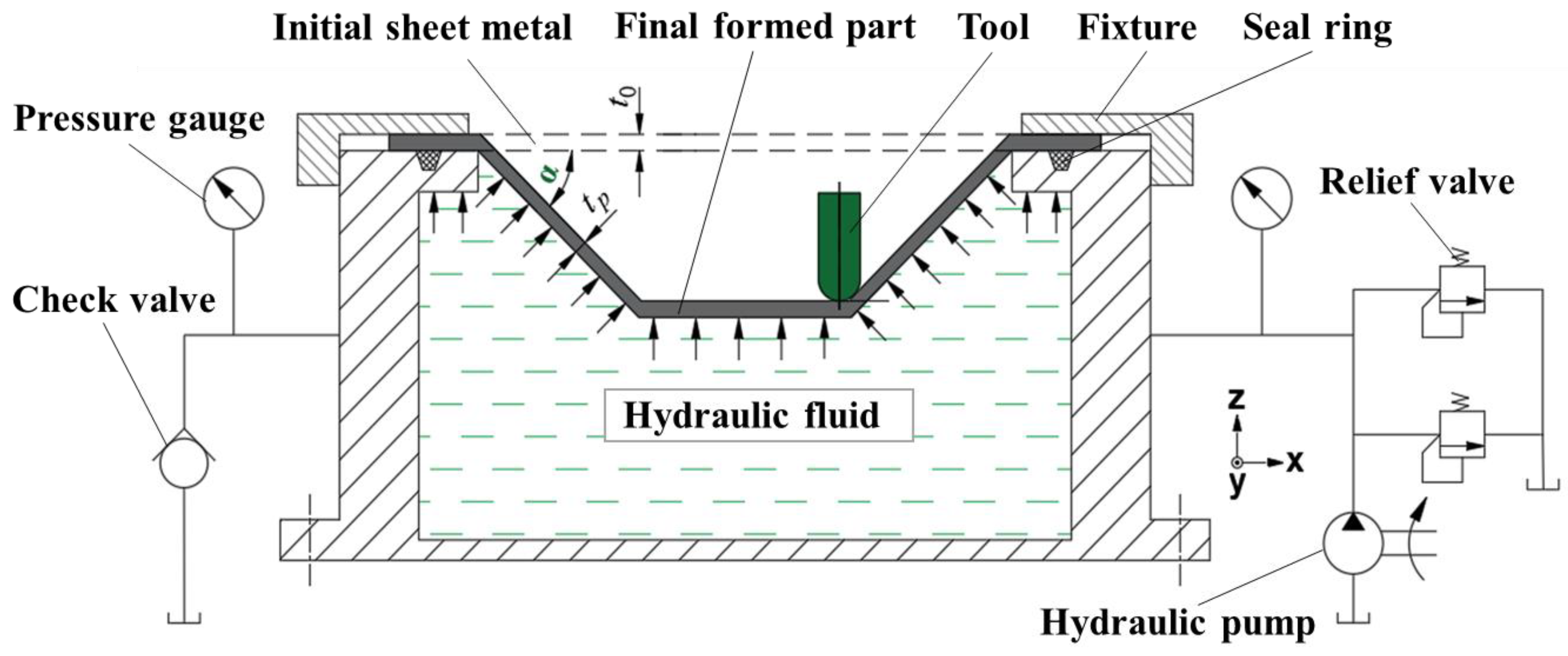
2.1. Design of HS-SPIF System

The HS-SPIF device adds pressure-controlled hydraulic oil to the back of the suspended sheet on the basis of SPIF, which enables the formed sheet to be supported by static pressure with different pressures and variable pressure support at different stages. Figure 1 shows the schematic diagram of the HS-SPIF principle. The hydraulic system includes a fuel tank, hydraulic pump, pressure gauge, relief valve, check valve, sealing ring, and hydraulic hose. By adjusting the relief valve and monitoring the pressure gauge, the preset pressure can be applied to the back of the sheet to be formed.
In the forming process, in order to accurately adjust the value of hydraulic pressure and realize stage-by-stage variable pressure control, two low-pressure relief valves are installed on the oil intake line of the cavity. In order to accurately measure the applied pressure, a hydraulic pressure gauge with a measuring range of 0.25 MPa is installed on the oil intake line and the oil outlet line.

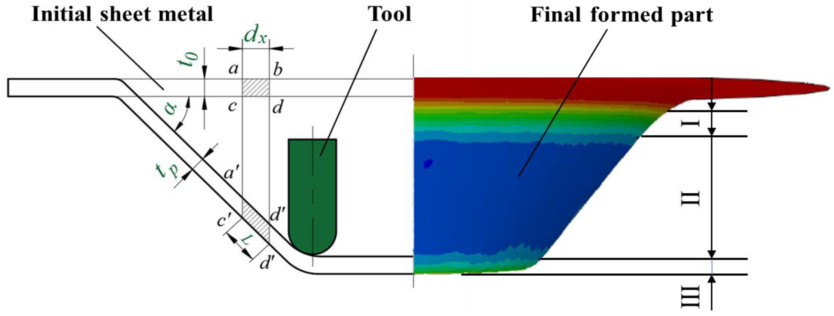
2.2. Critical Angle of Uniform Thickness

In the process of single-pass truncated pyramid forming, it is assumed that there is no radial flow and only shear deformation, which satisfies the principle of volume invariance in material plastic deformation. The schematic diagram of the wall thickness change is shown in Figure 2, the left part of the Figure is the schematic diagram of the theoretical change, and the right part is the schematic diagram of the simulation change. Under the combined action of tool head pressure and hydraulic support, the sheet produces continuous tensile thinning along the sidewall, the wall thickness gradually decreases from the initial wall thickness t0 to tp, and the forming angle between the sidewall and the horizontal line of the target part is α. Along the Z direction, these parts are divided into three regions: I, II, and III, among which I is the excessive bending zone, II is the main deformation zone, and III is the stable bottom zone. The initial element abcd of length dx becomes a parallelogram a’b’c’d’ with an L side length after plastic deformation. Based on the assumption of volume constancy,
t 0   ·   d x = t p   ·   L ,   d x = L   ·   cos α .
That is,
t p = t 0   ·   cos α .
From Equation (2), it is obtained that the wall thickness is the theoretical wall thickness of single-pass incremental forming. In the process of truncated pyramid forming, with the gradual increase of the forming angle, the side wall of the part will gradually show a banded thin-walled area in the circumferential direction, that is, the “thinning zone”. Before the appearance of the thinning band, the wall thickness of the product is basically consistent with the theoretical wall thickness calculated by the cosine law, and the distribution of the wall thickness is basically uniform.
In general, when judging whether there is excessive thinning or not, as long as the error between the wall thickness T of the main deformation zone and the theoretical wall thickness t p of the cosine theorem after sheet metal forming is less than ± 10 % [20,27], which satisfies Equation (3), it is considered that there is no excessive thinning of the formed parts. Therefore, the wall thickness is approximately uniformly distributed in the forming process.
0 . 9 t p   T     1 . 1 t p
If Equation (2) is substituted into Equation (3), then.
0 . 9 t 0 cos α     T     1 . 1 t 0 cos α .
It can be seen from Equation (4) that when the initial wall thickness t0 is constant, the forming angle α is an important factor affecting the uniform distribution of wall thickness. The maximum forming angle α max without excessive thinning is called the uniform critical forming angle θ of wall thickness. That is, when the forming angle is α max , the wall thickness of the main deformation zone of the part satisfies Equation (4); when the forming angle is α max + 1 ° , the wall thickness of the main deformation zone of the part does not satisfy Equation (4), and the maximum forming angle α max is regarded as the wall thickness uniform critical forming angle θ , which is referred to as the critical angle.

2.3. Finite Element Model and Analysis Method

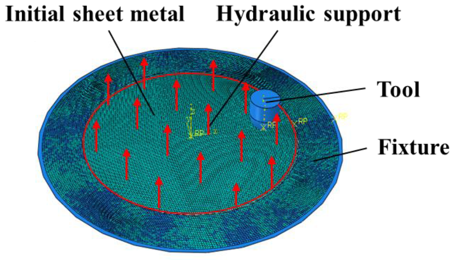
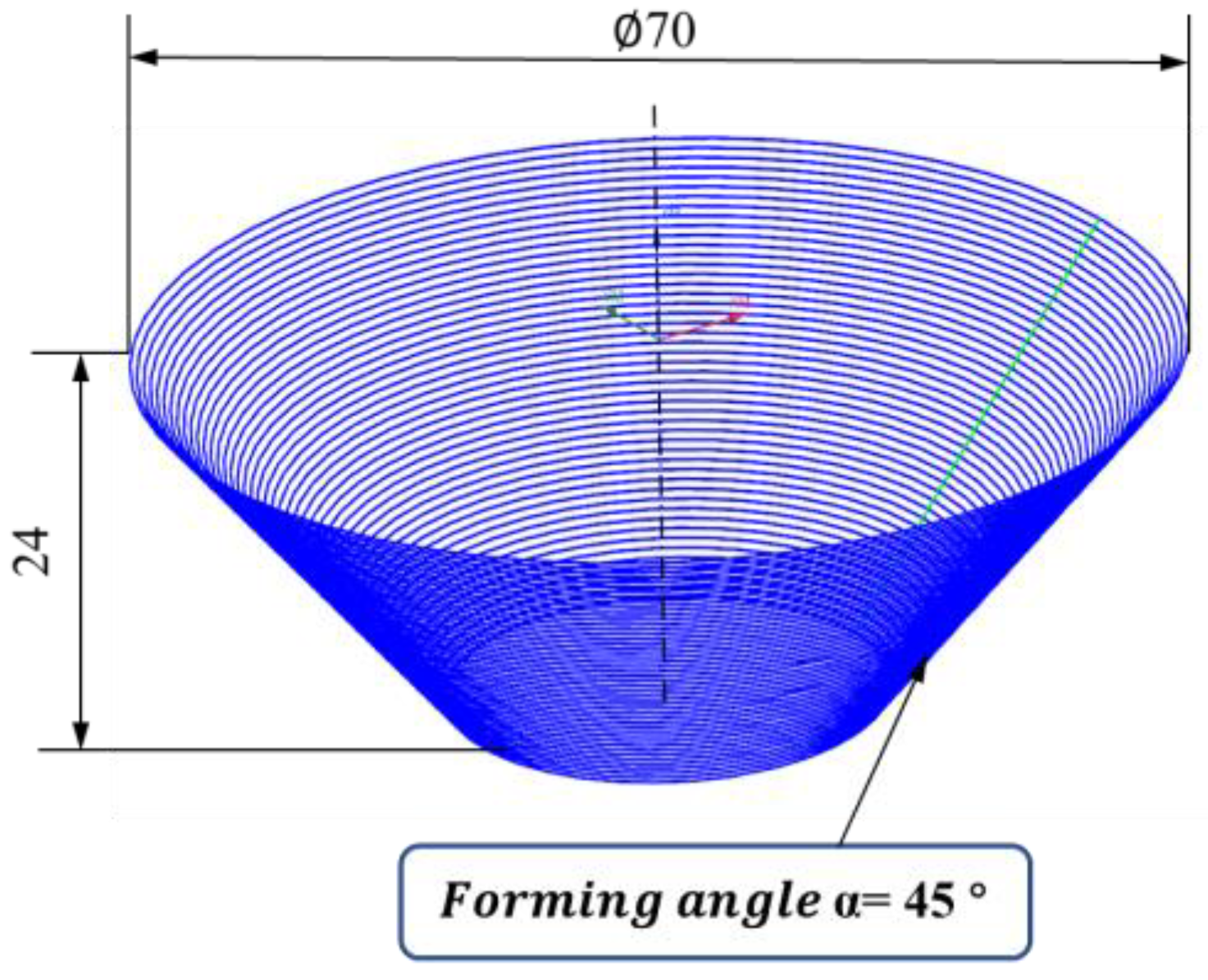
2.3.1. Establishment of Finite Element Model

In order to analyze the influence of different hydraulic parameters on the wall thickness distribution and critical angle in the process of single-pass truncated pyramid forming, it is necessary to establish the finite element model of HS-SPIF.
Using ABAQUS®/Explicit 6.14 software, a simplified finite element model of the HS-SPIF process is established, as shown in Figure 3. When the sheet metal is pressurized to 1.6 bar, the final shape of the 45° truncated pyramid is simulated, as shown in Figure 4.
The HS-SPIF finite element model includes the initial sheet metal, the forming tool head, and the fixture. A circular aluminum sheet with a diameter of 136 mm and an initial thickness of 1 mm is used in the simulation. The diameter of the tool head is 14 mm. For the fixture, we used a circle with an outer ring radius of 70mm and an inner ring radius of 55 mm. For both the fixture and the tool head, we adopt an analytical rigid body model. The edge of the sheet is clamped by the fixture. Therefore, the six degrees of freedom of the upper and lower sheets are constrained. During the forming process, the rotation of the sheet metal in the X, Y, and Z directions is constrained so that only plastic deformation occurs; the rotation of the tool head in the X and Y directions is restrained so that the displacement in the X, Y, and Z directions and the rotation in the Z direction may occur. The sheet is considered to be a deformable body, and the shell element of the S4R reduction integral is used for meshing. The unit dimension is 1 mm × 1 mm, the number of units is 17,606; and the number of nodes is 17,821. When the six degrees of freedom of the edge surface of the sheet are constrained, and the tool head rotates around the plate, the type of contact between the tool head and the sheet is surface-to-surface contact. For the friction behavior, we adopt Coulomb Friction Law, and the friction coefficients between the sheet and the fixture and between the sheet and the tool head are set at 0.2 and 0.1, respectively.
In this study, an Al 1060 sheet with a thickness of 1.004 mm was used for the tensile test, and the mechanical properties of the sheet were tested by rolling, diagonal and transverse experiments. It can be supposed that the material is isotropic [28,29], and the true stress values for three directions can be averaged, similar to r-value averaging, as shown in Equation (5):
σ ¯ = σ 0 + 2 σ 45 + σ 90 4
The true stress-strain curve can be fit by the Hollomon power law, as shown in Equation (6):
σ ¯ = K ε ¯ n
where K is the strength coefficient, n is the strain-hardening exponent, σ ¯ is flow stress, and ε ¯ is plastic strain.
The true stress-strain curve obtained from the tensile test is shown in Figure 5. The ratio of stress to strain is Young’s modulus. On this basis, the material properties of the Al 1060 sheet with a thickness of 1.004 mm are summarized in Table 1.
The CAD shape of the forming truncated pyramid table is imported into NX CAM 10.0, which can generate the tool motion trajectory and be used to define the tool motion during the forming process. Contour milling is adopted, and the lower pressure of each layer is set at 0.5 mm during forming. In the finite element simulation and experimental test, the diameter of the forming truncated pyramid table is 70 mm, and the height is 24 mm. Figure 6 shows the motion path of the contour milling tool with a forming angle of 45°.

2.3.2. Analysis Method

Based on the established HS-SPIF model, the effects of different hydraulic parameters on the wall thickness distribution and critical angle can be analyzed by modifying the hydraulic load on the lower surface of the sheet. First of all, under different hydraulic parameters, the pressure range of favorable wall thickness distribution is found by single-pass incremental forming and truncated pyramid parts with α = 45° and α = 50°. Then, in the favorable pressure range, according to the order of pressure from small to large, the forming angle corresponding to different hydraulic values is determined through gradual pressurization.

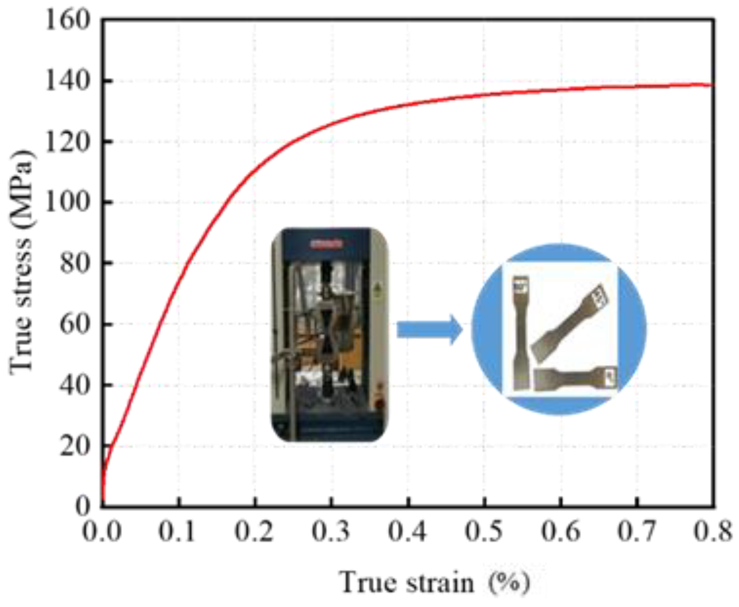
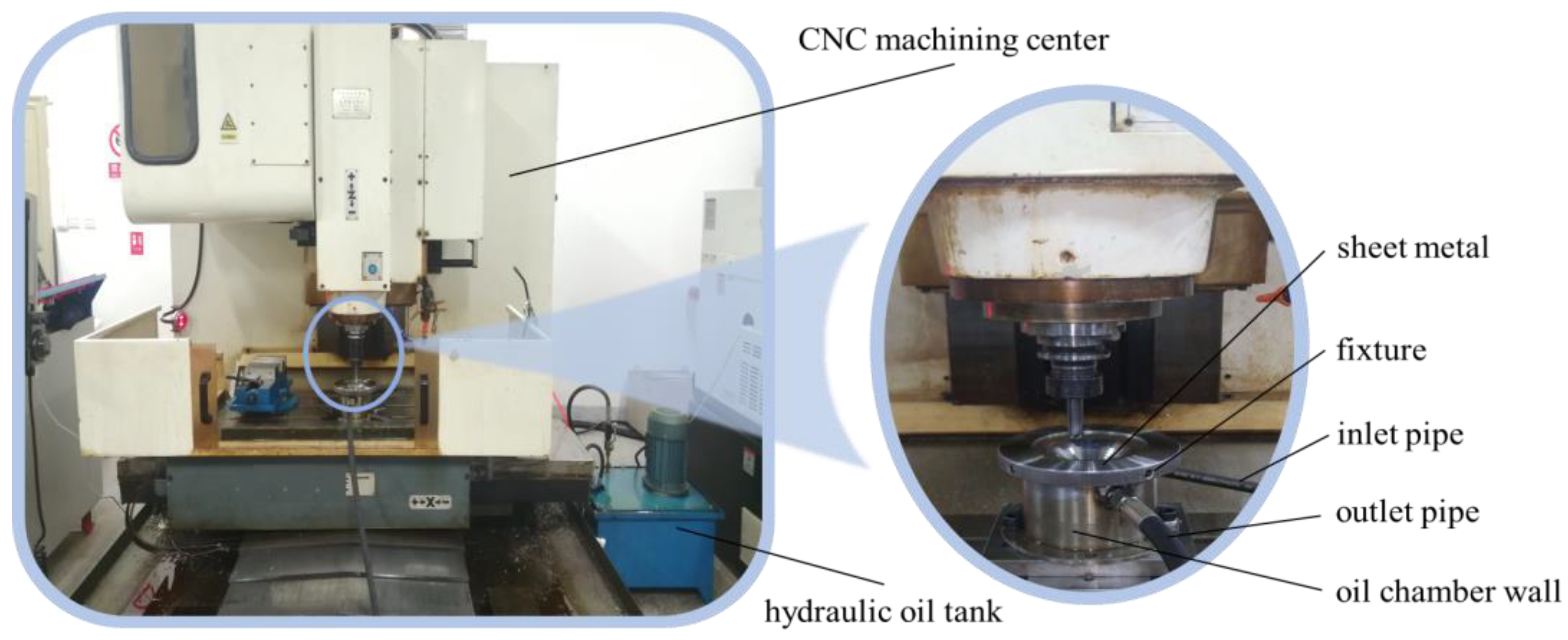
2.4. Experimental Equipment and Verification Scheme

2.4.1. Experimental Equipment

Experimental tests are carried out on the HS-SPIF experimental system equipment to verify the correctness of the simulation. Table 2 shows the equipment of the HS-SPIF experimental system.
Figure 7 shows the experimental system of HS-SPIF. In the experiment, the sheet to be formed is fixed on the upper part of the oil cavity through the fixture, and the oil inlet and outlet of the hydraulic system are arranged on the side wall of the oil cavity. The magnitude and variation of the uniform critical angle of wall thickness under different hydraulic parameters are studied by quantitatively controlling hydraulic oil pressure.

2.4.2. HS-SPIF Experimental Verification Scheme

The verification experiments include the minimum critical angle, the critical middle angle, and the maximum critical angle obtained by HS-SPIF simulation. At the same time, under the hydraulic parameters corresponding to each critical angle, two forming angles adjacent to the critical angle must be tested to analyze the critical angles corresponding to different hydraulic parameters under experimental conditions.
In the course of the experiment, the selected sheets are consistent with the finite element simulation; both are Al 1060 sheets with a diameter of 136 mm and an initial thickness of 1 mm. The tool head material is quenched high-speed steel with a diameter of 14 mm. Using the tool path and machining program generated by NX CAM 10.0, the program is input into the CNC vertical milling machine, and the sheet metal is machined by controlling the forming tool head. The feed speed is 600 mm/min, and the tool head speed is 700 r/min.

3. Results

This part includes two aspects: simulation results and experiment results. First, Section 3.1 and Section 3.2 provide the results of the finite element simulation of the cases studied in Section 2.3.2. Then, Section 3.3 provides the experimental results of the Section 2.4.2 HS-SPIF verification scheme and compares it with the finite element simulation and theoretical values.

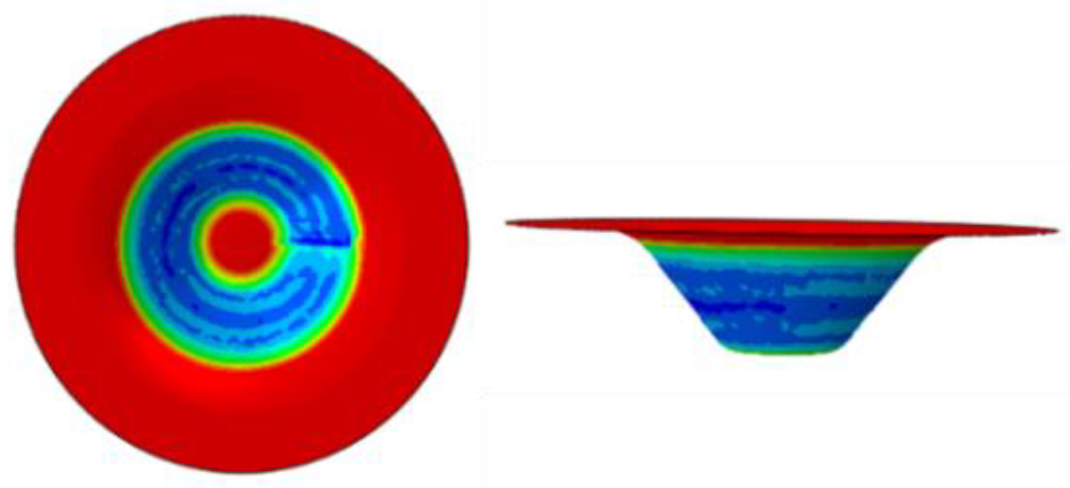
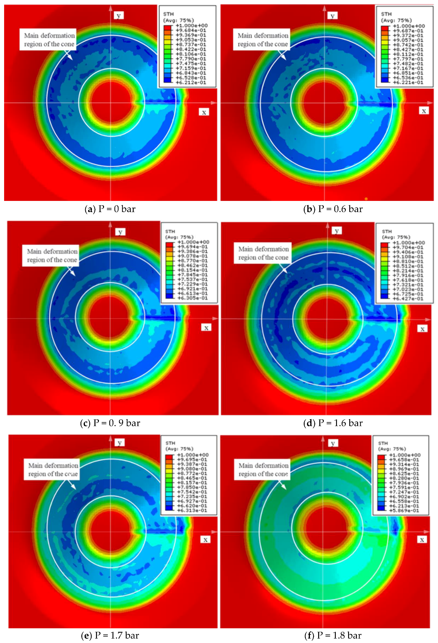
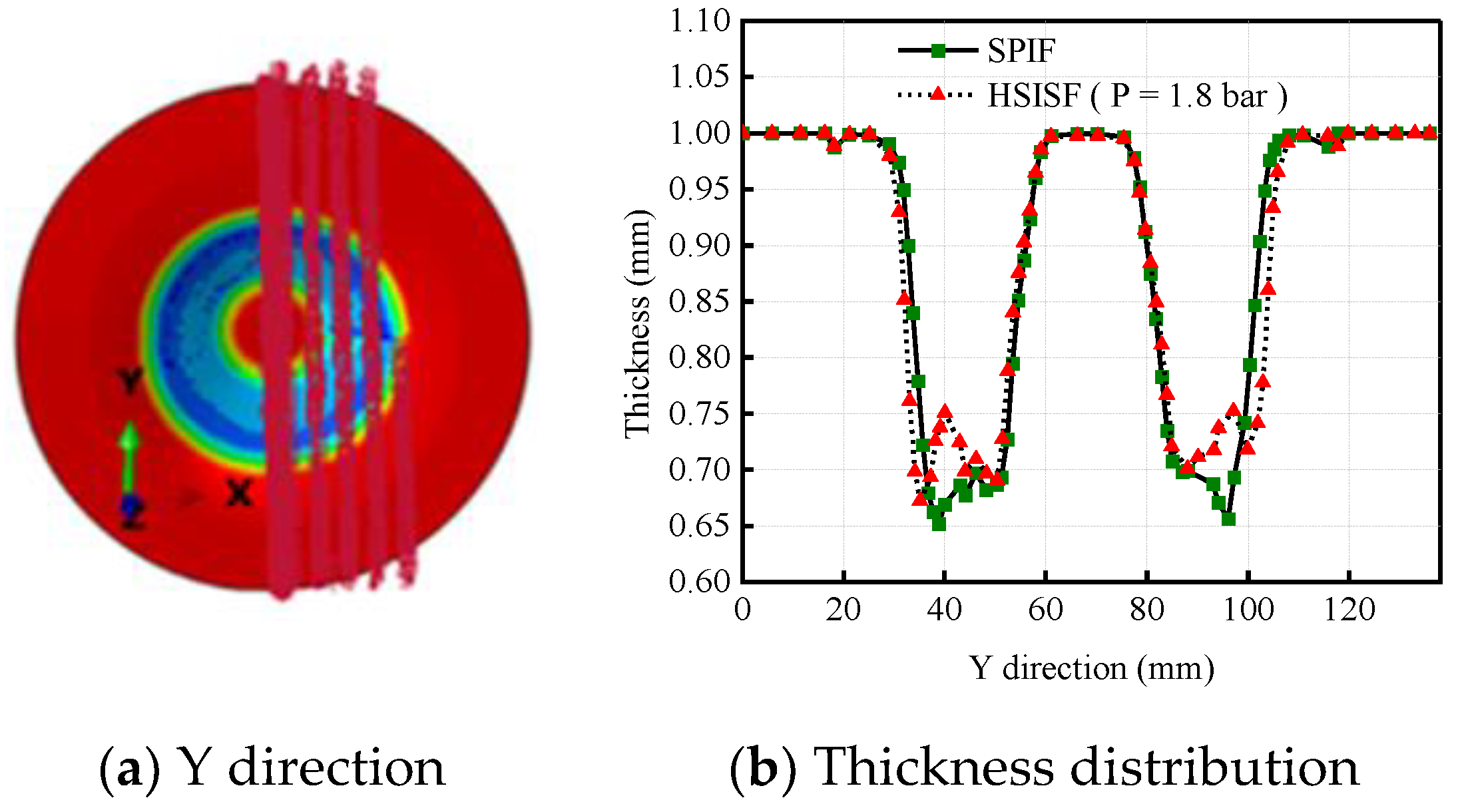
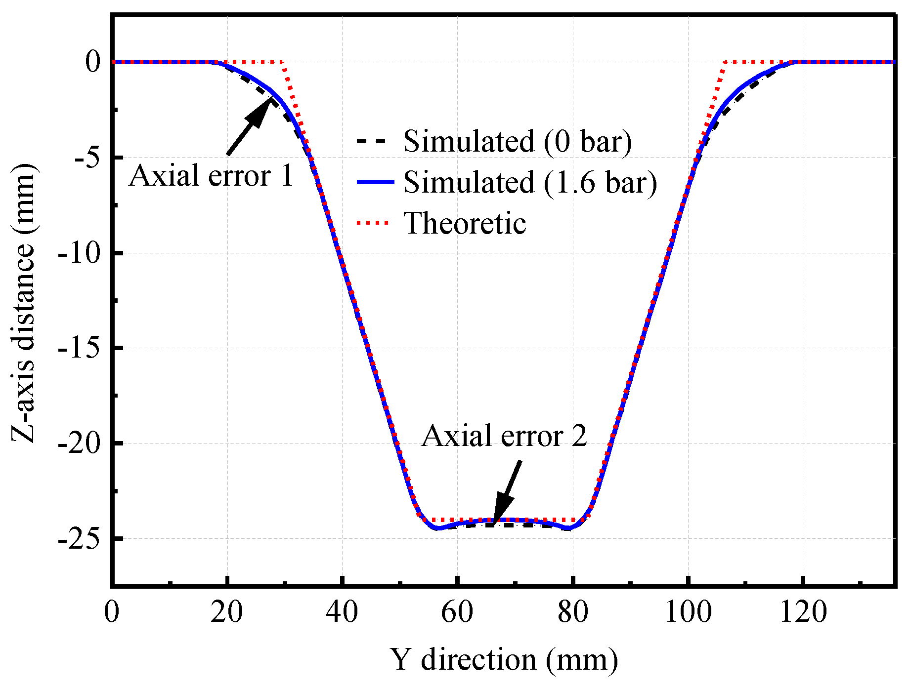
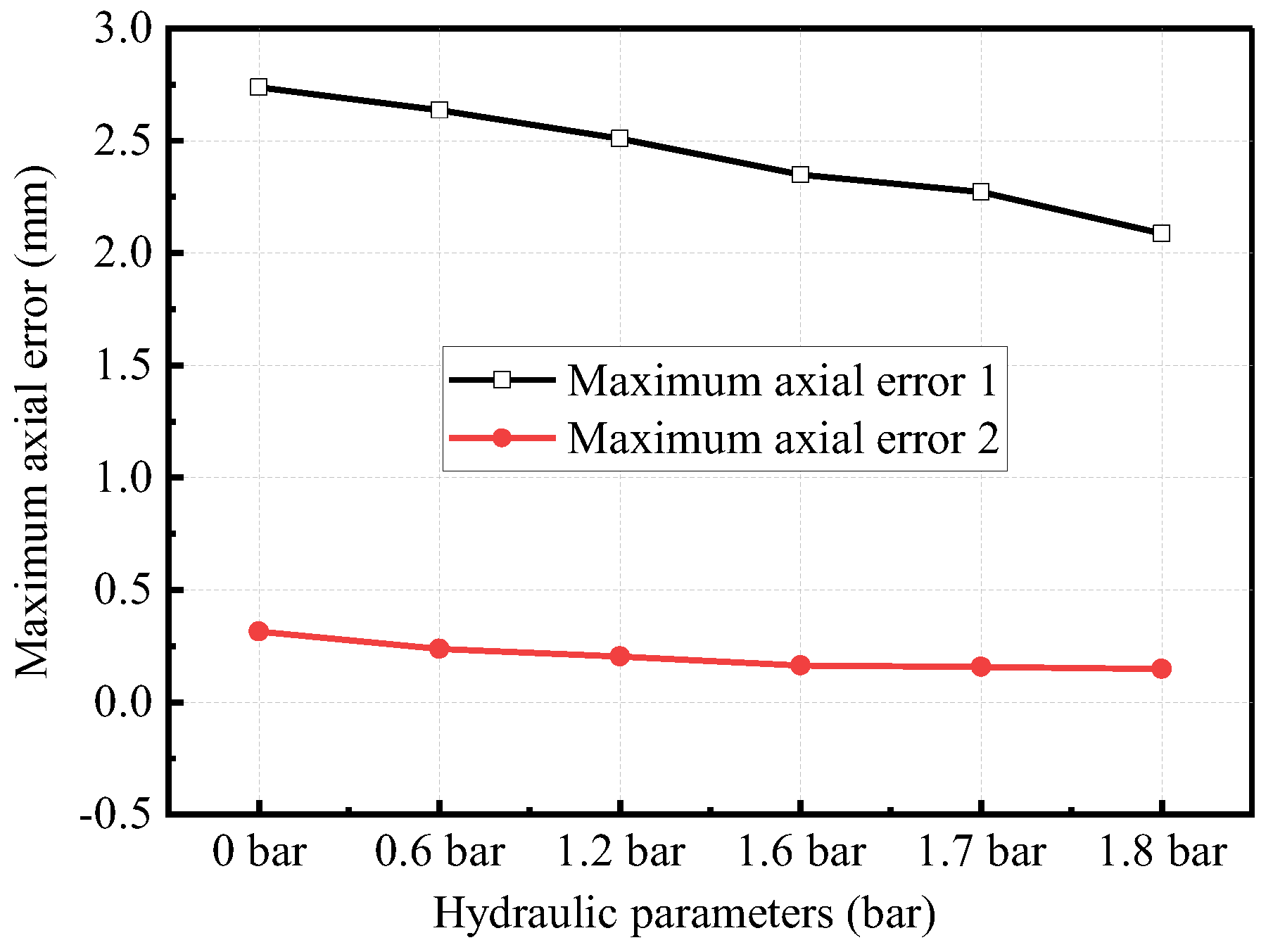
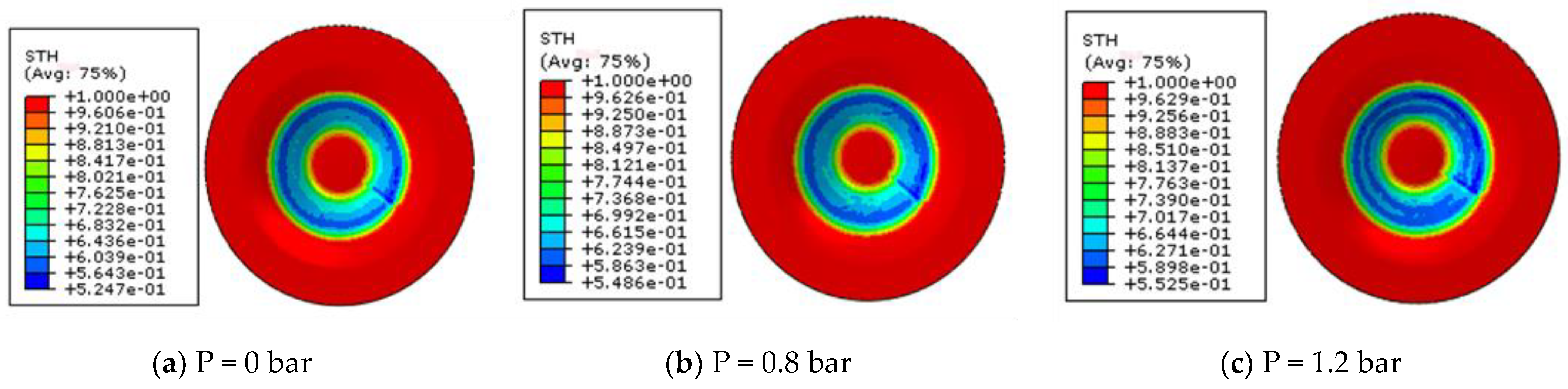
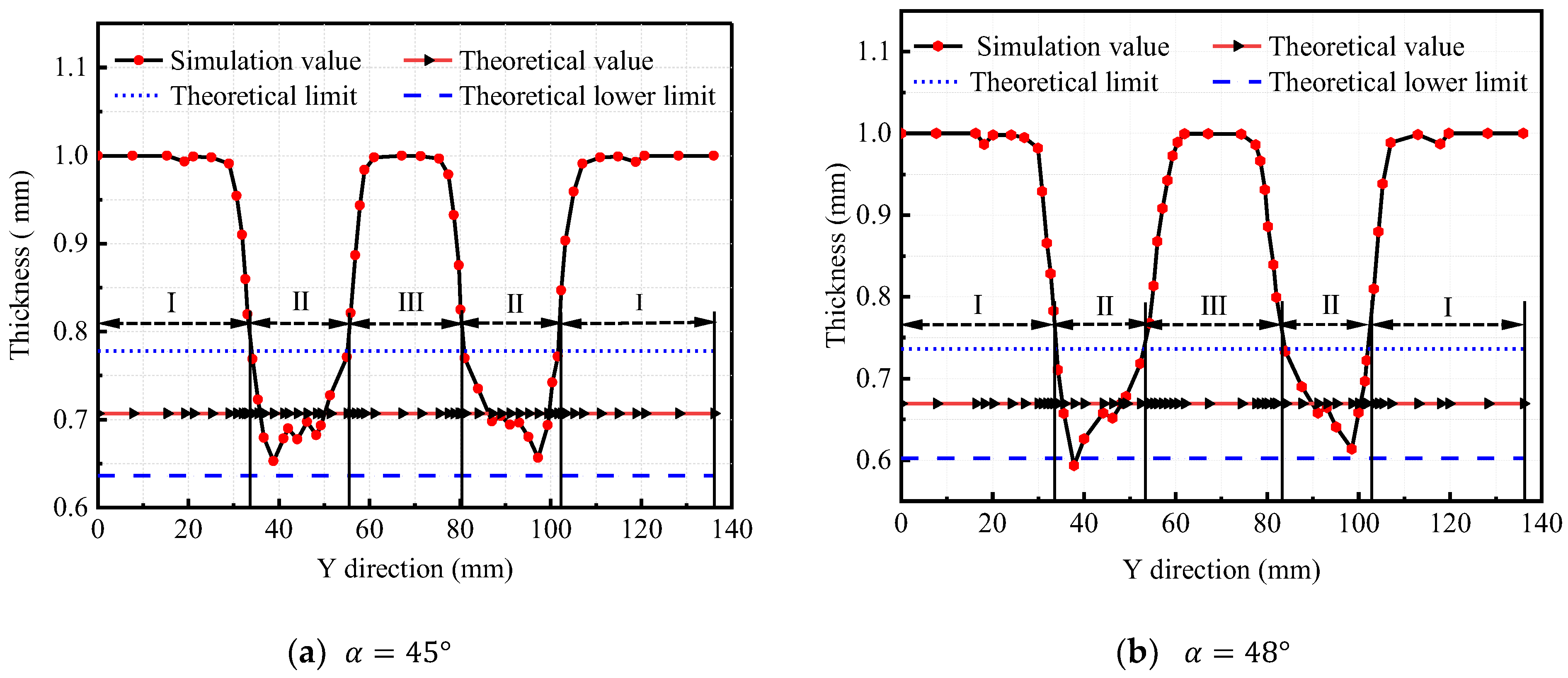
3.1. Simulation Results of Wall Thickness Distribution

In order to analyze the influence of different hydraulic parameters on the wall thickness distribution, the truncated pyramid parts with single-pass incremental forming α = 45° and α = 50° under different support pressure are selected in this case. Through simulation, it is found that the favorable pressure range is 0–1.7 bar.
Firstly, the truncated pyramid with a 45° wall angle was formed when the supporting pressure was 0 bar, 0.3 bar, 0.6 bar, 0.9 bar, 1.2 bar, 1.5 bar, 1.6 bar, 1.7 bar, and 1.8 bar, respectively. Figure 8 shows the cloud map of thickness distribution at key pressure nodes at 0–1.8 bar, and Figure 8a at 0 bar is also the cloud map of thickness distribution when SPIF is used.
Figure 8a shows that obvious thinning bands (dark blue) appear in the first third of the main forming zone II of ordinary single-point incremental forming, which is also the area most prone to excessive thinning. With the gradual increase of the pressure, the thinning band spreads to the center of the sheet. From Figure 8a–f, the material points in the main forming zone move, and the “sprue pulling” movement occurs on the sheet surface. The blue area is getting wider, but the color is getting lighter, and when you reach Figure 8f, the dark blue thinning band nearly disappears. This phenomenon shows that with the increase of pressure, the over-shallow area becomes less and less, and the wall thickness distribution becomes more and more uniform. This is because in the ordinary SPIF process, there is no support on the lower surface of the sheet, and the excessive local stress on the upper surface of the sheet results in over-concentrated strain. Concentrated strain easily causes sheet instability and fracture, resulting in uneven wall thickness distribution, and an obvious thinning zone will appear. In the HS-SPIF process, the flexible support pressure helps to slow down the local deformation of the sheet, improve stability in the deformation process, and promote the uniform distribution of wall thickness.
In order to quantitatively analyze the influence of hydraulic pressure on the wall thickness distribution of the 45° truncated pyramid, the minimum wall thickness under different pressures was compared. The results show that when the pressure is less than 1.7 bar, the minimum wall thickness is greater than 0 bar (i.e., SPIF). Comparing Figure 8a with Figure 8f, it is found that the minimum wall thickness at 1.8 bar is less than the minimum wall thickness at 0 bar. In order to quantitatively analyze the wall thickness distribution of more nodes at 0 bar and 1.8 bar, 137 nodes on the Y direction of the inner surface of the parts under these two pressures were selected to form a node path, as shown in Figure 9a. The wall thickness distribution curve of SPIF and HS-SPIF (1.8 bar) in the Y direction is shown in Figure 9b. As seen from Figure 9b, compared with the SPIF process, the wall thickness of the parts formed by the HS-SPIF process with a pressure value of 1.8 bar is more prone to excessive thinning in the local micro range. Compared with the wall thickness in the SPIF process, the wall thickness of 1.8 bar is reduced by 0–0.045 mm, which is a 6.91% decrease. This shows that hydraulic support of 1.8 bar can be used for sheet forming; however, hydraulic support of 1.8 bar is a disadvantage for an even distribution of wall thicknesses.
In order to study the influence of hydraulic pressure on sheet forming accuracy, the displacement on the Z axis is taken along the Y path. Figure 10 shows the simulated profile curve when the pressure is 0 bar (i.e., SPIF) and 1.6 bar and the theoretical profile curve. The height difference between the simulated profile and the theoretical profile at each node is the axial error. Figure 10 shows axial error 1 in the bending transition zone and axial error 2 in the stable bottom zone, and the axial error when the pressure is 0 bar is greater than that when the pressure is 1.6 bar. Figure 11 shows the maximum axial error for different hydraulic parameters. As shown in Figure 11, compared with axial error without no hydraulic support, the axial error with hydraulic support can be reduced by 0.007–0.652 mm, i.e., hydraulic support can cause the axial error to reduce by 52.3%. Figure 10 and Figure 11 show that hydraulic support helps to reduce spring back and improve the forming accuracy and quality of parts.
Then, when the supporting pressure is 0 bar, 0.4 bar, 0.8 bar, 1.2 bar, 1.4 bar, 1.6 bar, 1.7 bar, and 1.8 bar, the truncated pyramid parts with a 50° wall angle are formed, respectively. The cloud map of thickness distribution at critical pressure nodes is shown in Figure 12. In the first half of the Y direction, the thickness distribution curve in the main forming zone II is shown in Figure 13.
It can be seen from Figure 12 that with the increase of hydraulic pressure, the dark blue thinning zone gradually spreads in the main forming zone II, and then it disappears gradually. This shows that the hydraulic support can also promote the uniform distribution of corner wall thickness in 50° forming. As can be seen from Figure 13, when the pressure value is below 1.7 bar, the Y direction is most prone to excessive shallowness in the local range, and the wall thickness with hydraulic support is greater than that without hydraulic support. When the pressure is 1.8 bar, the wall thickness of HS-SPIF is smaller than that of SPIF without hydraulic support in the local small over-thinning area (near 36 mm of Y direction in the figure).
According to the research of Yang et al. [30], the strain in the Z direction can be equivalent to tensile plastic deformation, and its plastic strain component εz first reaches the strain limit of an aluminum sheet. The plastic strain component εz along the Y direction under different pressures is shown in Figure 14. It can be seen from the figure that with the increase in pressure, the maximum plastic strain component εz decreases from 0.465 to 0.418. Compared with SPIF (i.e., 0 bar), hydraulic support can reduce plastic strain by 11.2%. This shows that the hydraulic support helps to reduce the plastic strain and promote the plastic forming of the sheet metal. The maximum plastic strain of the blank sheet in this Figure is 0.465, which is less than 0.795 in Figure 5, so the sheet does not fail.
The minimum wall thickness under each pressure is extracted from the cloud images of α = 45° and α = 50° thickness distribution, and the minimum thickness variation curve under various hydraulic parameters is obtained, as shown in Figure 15, where in forming truncated pyramid parts with different angles, the influence trend of hydraulic parameters on wall thickness distribution is consistent. When the hydraulic value is 0–1.7 bar, the minimum wall thickness increases with the increase of hydraulic pressure. When the hydraulic value is greater than 1.7 bar, the minimum wall thickness decreases sharply and is less than the minimum thickness of SPIF. This shows that when the HS-SPIF process forms the truncated pyramid parts with different angles, the favorable pressure range to promote the uniform distribution of wall thickness is 0–1.7 bar. In this range, the hydraulic support can increase the minimum wall thickness by 0.039 mm. Compared with SPIF, HS-SPIF can increase the minimum wall thickness by 0–6.93%. Therefore, after using the HS-SPIF process to analyze the critical angle of uniform wall thickness distribution, the hydraulic pressure setting range is 0–1.7 bar.

3.2. Simulation Results of Critical Angle

In this section, according to the definition of critical angle in Section 2.2, it is determined that the critical angle of SPIF is 46° and the range of critical angle of HS-SPIF is 47 53 ° . The following, combined with the simulation results, are explained respectively.

3.2.1. Assessment of SPIF Critical Angle

The other process parameters remain unchanged, and the finite element simulation of the α = 45° and α = 48° truncated pyramids is carried out. Figure 16 shows the variation curve of the wall thickness of the key nodes in the Y direction when the forming angles are 45° and 48°. As seen from Figure 16a, at that time, when α = 45°, the wall thickness of the main deformation zone of the formed part was within the limit required for uniform distribution of wall thickness. However, it is found from Figure 16b that when α = 48°, the minimum wall thickness of the main deformation zone is less than the lower limit of the theoretical wall thickness. It shows that the phenomenon of excessive thinning occurs in the main deformation zone when the forming angle is 48°. Therefore, it can be determined from Figure 16 that the critical angle of the truncated pyramid parts is between 45 48° when the SPIF process is used.
From Figure 16, it is found that the wall thickness distribution of the main deformation zone II is smaller than the upper limit of the theoretical wall thickness, and the slight difference is related to the extrusion deformation of the material caused by the large tool head radius and the reverse flow of the material. The lower limit of theoretical wall thickness is directly related to the excessive thinning of the sheet. Therefore, this paper focuses on whether the wall thickness of each node is above the lower limit of the theoretical wall thickness. At the same time, the changing trend of wall thickness is symmetrical about the center of the sheet, and the minimum value of wall thickness near the starting point of the tool is slightly smaller than that of the end point of the tool. Therefore, the judgment condition of the critical angle can be simplified, the first half of the direction near the starting point of the tool is selected, and the critical angle is judged by the fact that the minimum simulated wall thickness in this direction is greater than the lower limit of the theoretical wall thickness. In order to accurately determine the critical angle in SPIF, it is necessary to further simulate the truncated pyramid with the forming angles 46 ° and 47°. As is shown in Figure 17, when α = 46 ° , the minimum value of the simulated wall thickness is greater than the lower limit of the theoretical wall thickness, while the minimum value of the simulated wall thickness is less than the lower limit of the theoretical wall thickness. At this time, according to the definition of uniform critical forming angle of wall thickness, the critical angle θ = α max = 46 ° of Al 1060 sheet with 1 mm wall thickness can be determined when the SPIF process is used to form truncated pyramid parts.

3.2.2. Assessment of HS-SPIF Critical Angle

In order to obtain the critical angles under different hydraulic parameters, different forming angles can be gradually pressurized in the range of 0 1.7 bar to obtain the corresponding pressure values of each critical angle. The critical angle of SPIF is also the critical angle of HS-SPIF without pressure; that is, the critical angle of HS-SPIF at 0 bar is 46°. The truncated pyramid parts with 47° and 48° forming angles were gradually pressurized from 0.05 bar, and the finite element simulation was carried out at 0.05 bar each time. Figure 17 shows the simulated thickness distribution corresponding to the critical angle when the pressure is 0.3 bar and 0.7 bar, respectively. Figure 18a shows that the critical angle is 47° when the hydraulic pressure is 0.3 bar, and Figure 18b shows that the critical angle is 48° when the hydraulic pressure is 0.7 bar. Similarly, the critical angles at 0.8 bar, 1.4 bar, 1.6 bar, 1.65 bar, and 1.7 bar are 49°, 50°, 51°, 52°, and 53°, respectively. The relevant data of critical angles obtained by HS-SPIF simulation are shown in Table 3, where the leftmost part is the hydraulic pressure value, while the rightmost part is the final simulated critical angle under a specific pressure value.
In Table 3, the critical angles under different hydraulic parameters can be obtained by comparing the minimum simulated wall thickness of two adjacent forming angles with the lower limit of theoretical wall thickness. For example, when the pressure P = 0.3 bar, the minimum simulated wall thickness in the 47° Y direction is greater than the lower limit of the theoretical wall thickness, while the minimum simulated wall thickness in the 48° Y direction is less than the lower limit of the theoretical wall thickness. Therefore, it can be seen from the table that the critical angle θ of 0.3 bar is 47°. The simulation data of 0.3 bar in Table 3 come from Figure 18a. Similarly, the simulation data of other pressures come from the corresponding wall thickness distribution curve.
The diameter of the sheet used in the simulation and experiment is 136 mm, and the total Y direction length of the part port is 136 mm. The direction generates a total of 137 nodes, and the distance between the two adjacent nodes is about 1 mm. The diameter of the top of the forming truncated pyramid is 70 mm, so the tool head begins to press down near the 34th node. It can be seen from Table 3 that the minimum simulation wall thickness appears at 38–41st nodes and at 35–39 mm of the direction. The node number and direction distance decrease with the increase of the forming angle, which is related to the variation law where the larger the angle, the greater the slope. The location of node number and direction distance shows that the most serious part of sheet thinning is in the first third of the main deformation zone. This is consistent with the simulation results in Figure 16.
To summarize, in HS-SPIF, the influence of pressure value on the critical angle can be shown in Figure 19. When the pressure is in the range of 0–1.7 bar, the critical angle of HS-SPIF will increase with the pressure. Especially when the pressure is in the range of 1.4–1.7 bar, the influence of hydraulic pressure on the critical angle is the most sensitive. In the same other working conditions, the uniform critical angle of the wall thickness of the HS-SPIF process (53°) is 7° higher than that of the SPIF process (46°) when the single-pass incremental forming of truncated pyramid parts. Therefore, the HS-SPIF process is beneficial to the uniform distribution of sheet wall thickness.

3.3. HS-SPIF Experimental Results

In the experiment, different pressures (0 bar, 1.6 bar, 1.7 bar, and 1.8 bar) were used to process 45° truncated pyramid parts, which were used to verify the range of favorable pressures. Five different hydraulic pressures (0 bar, 0.3 bar, 0.8 bar, 1.4 bar, and 1.7 bar) were used to process the target parts with different forming angles, which were used to verify the critical angles under different pressures. During the experiment, other parameters (such as tool diameter, rotational speed, feed speed, reduction, sheet metal thickness, and material) are controlled. The experimental verification scheme and related parameters are shown in Table 4.
During the course of the experiment, the hydraulic pressure is adjusted by the relief valve. On the CNC machine tool, the target parts are machined by the HS-SPIF process. On the on-line cutting machine, the target part is cut along the Y direction, and the cut specimen is shown in Figure 20. Along the actual distance of the Y direction, the cutting specimen is calibrated, and the wall thickness from the direction’s starting point to the sheet metal’s central axis is measured. The measuring tool is shown in Figure 21. Taking the lower pressure point of the tool as the starting point, the wall thickness measuring point is set at every interval of 1 mm along the Y-axis direction, and the thickness of each point is measured using a double-tip spiral micrometer.
When the forming angle is 45°, the minimum wall thickness of the hydraulic pressure of 0 bar, 1.6 bar, 1.7 bar, and 1.8 bar in the Y direction is shown in Figure 22. By comparing the experimental wall thickness with the simulated wall thickness, it can be found that the variation trend of the minimum wall thickness along the Y direction is consistent. With increased hydraulic pressure, the minimum wall thickness first increases and then decreases. When the hydraulic value is 0–1.7 bar, the minimum wall thickness is greater than the minimum thickness of SPIF (0 bar); when the hydraulic value is 1.8 bar, the minimum wall thickness is less than the minimum thickness of SPIF. Therefore, the favorable range of pressure obtained by the experiment is 0–1.7 bar, and the experimental results are consistent with the simulation results. Meanwhile, it is found that when the hydraulic pressure is 0 bar, the difference between the experimental wall thickness and the simulated wall thickness is 0.01431 mm; when the hydraulic pressure is 1.6–1.8 bar, the difference between the experimental wall thickness and the simulated wall thickness is 0.0008–0.001 mm. This shows that the hydraulic support can effectively promote the uniform distribution of wall thickness, which is consistent with the simulation results in Figure 8. In addition, under the same pressure, due to the comparatively ideal model established in the simulation and various errors in the experiment, there are differences between the simulation wall thickness and the experimental wall thickness, though these differences do not affect the determination of the favorable hydraulic range.
Figure 23 shows the wall thickness distribution curve of the critical angle of SPIF obtained in the experiment. The figure shows that when α = 46°, the minimum value (0.648 mm) of the experimental wall thickness is greater than the lower limit (0.625 mm) of the theoretical wall thickness, while α = 47°, the minimum value (0.610 mm) of the experimental wall thickness is less than the lower limit (0.614 mm) of the theoretical wall thickness. Therefore, the critical angle of SPIF forming a truncated pyramid of Al 1060 sheet with a wall thickness of 1 mm is 46°. Therefore, the experimental results of the SPIF critical angle are consistent with the simulation results.
Figure 24 shows the wall thickness distribution curve of HS-SPIF at a pressure of 0.3 bar. The figure shows that the critical angle is 47° when the experimental pressure is 0.3 bar. At the same time, the critical angle of HS-SPIF is 48° when the pressure is 0.8 bar. Therefore, the experimental results of the critical angle obtained by HS-SPIF under different pressures are consistent with the simulation results.
Figure 25 shows the distribution curves of experimental wall thickness, simulated wall thickness, and theoretical wall thickness when the critical angles of HS-SPIF are 50° and 53°. Comparing the experimental wall thickness with the simulated wall thickness shows that the distribution trend of wall thickness is basically the same. When the hydraulic pressure and the forming angle are the same, there are some differences between the experimental and simulated values and the position of the minimum experimental wall thickness shifts to the right. This is because the model established in the simulation is ideal, and the influence of material radial flow is not taken into account. However, during the experiment, the tool head moves clockwise at each layer. Compared with the location of the minimum wall thickness at the critical angle of 46–53°, the experimental data are 1.136–3.293 mm lower than the simulation results. These differences and offsets are related to some assumptions in the simulation. For example, in the simulation, it is assumed that there is no radial flow in the sheet metal forming process, but the radial flow occurs in the experiment. Since these small differences do not affect the determination of the final critical angle, the experimental results and simulation results are effective.

4. Discussion

In this study, it is noted that there are some limitations in the finite element simulation and experimental tests, which are discussed below.
The proposed hydraulic support can not only realize the static pressure support as discussed in this paper but also has the potential of variable pressure support and dynamic pressure support. Although excessive hydraulic support causes excessive thinning in a small area of the main forming area (See Figure 9b), it can lead to more uniform distribution of overall thickness, which can be obtained from the thinning band that has basically disappeared in Figure 8f. Therefore, the follow-up work will be carried out based on the hydraulic experimental device designed in this paper to study the variable pressure control of the over-thinned area.
The uniform critical angle of wall thickness, as studied in this article, is an approximate expression of the uniform distribution of wall thickness and is based on the assumption that there is only shear deformation. This may cause the predicted critical angle to overestimate the actual critical angle. However, based on these results, the current research provides an effective and feasible method to evaluate the critical angle of uniform wall thickness distribution.
The critical angle evaluation of hydraulic support single-point incremental forming is only suitable for truncated pyramid parts with a fixed angle in single-point forming of Al 1060 sheet. In order to facilitate the comparison of critical angles, ordinary ISPF is used as the basis of research, and some process parameters are set to constant. In reality, we can study the critical angle and optimize the parameters for different materials and different shapes of parts.

5. Conclusions

Based on the HS-SPIF process, this article designed an HS-SPIF experimental system, which was used to study the thickness uniformity and critical forming angle in single-pass hydraulic incremental sheet forming. Through finite element simulation, the favorable pressure range to promote the uniform distribution of thickness and the uniform critical angle of wall thickness corresponding to favorable hydraulic parameters are determined. The finite element simulation results are compared with the experimental results to evaluate the uniform critical angle of wall thickness in hydraulic support incremental sheet forming. The comparison of the critical angle between HS-SPIF and SPIF quantitatively shows the beneficial effect of the hydraulic support incremental sheet forming process on improving the uniform critical angle of wall thickness. Through this study, conclusions can be drawn as follows:
(1)
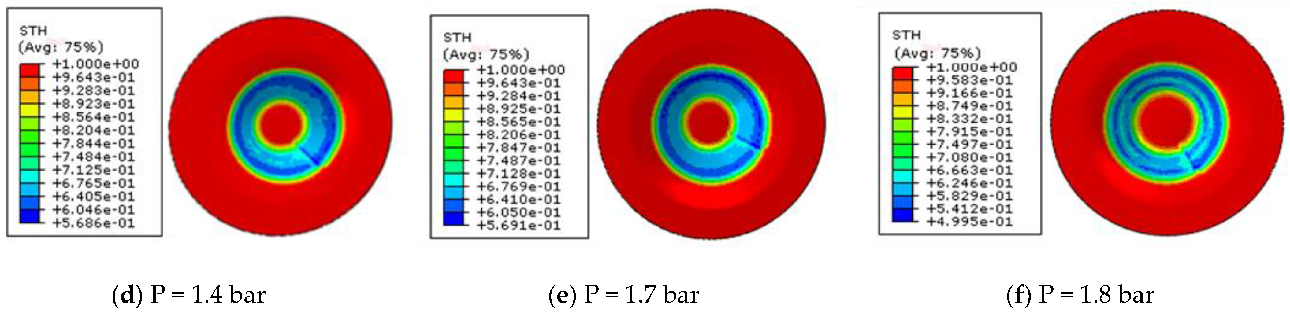
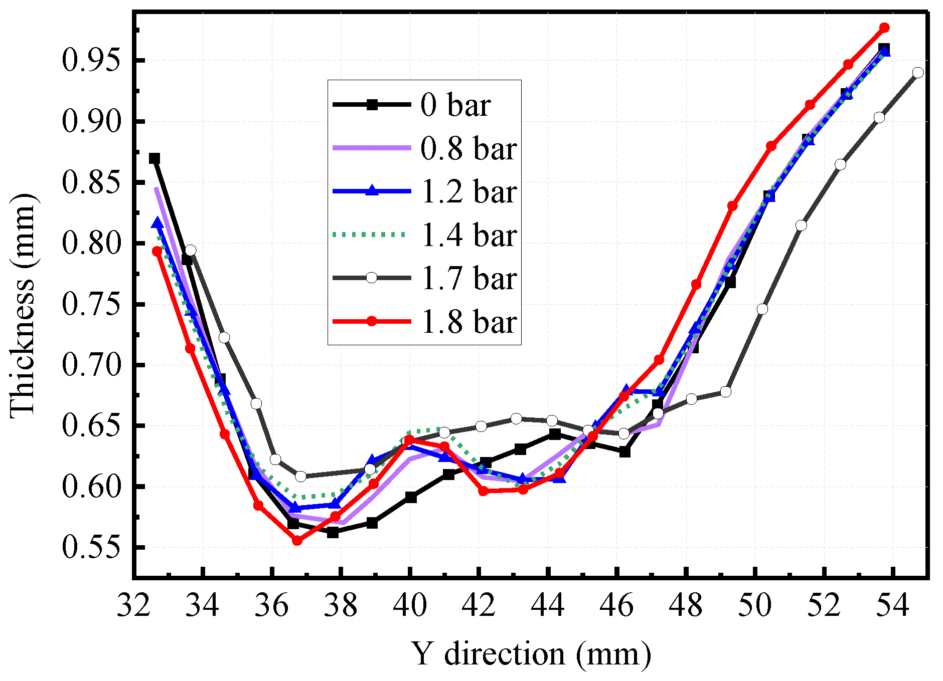
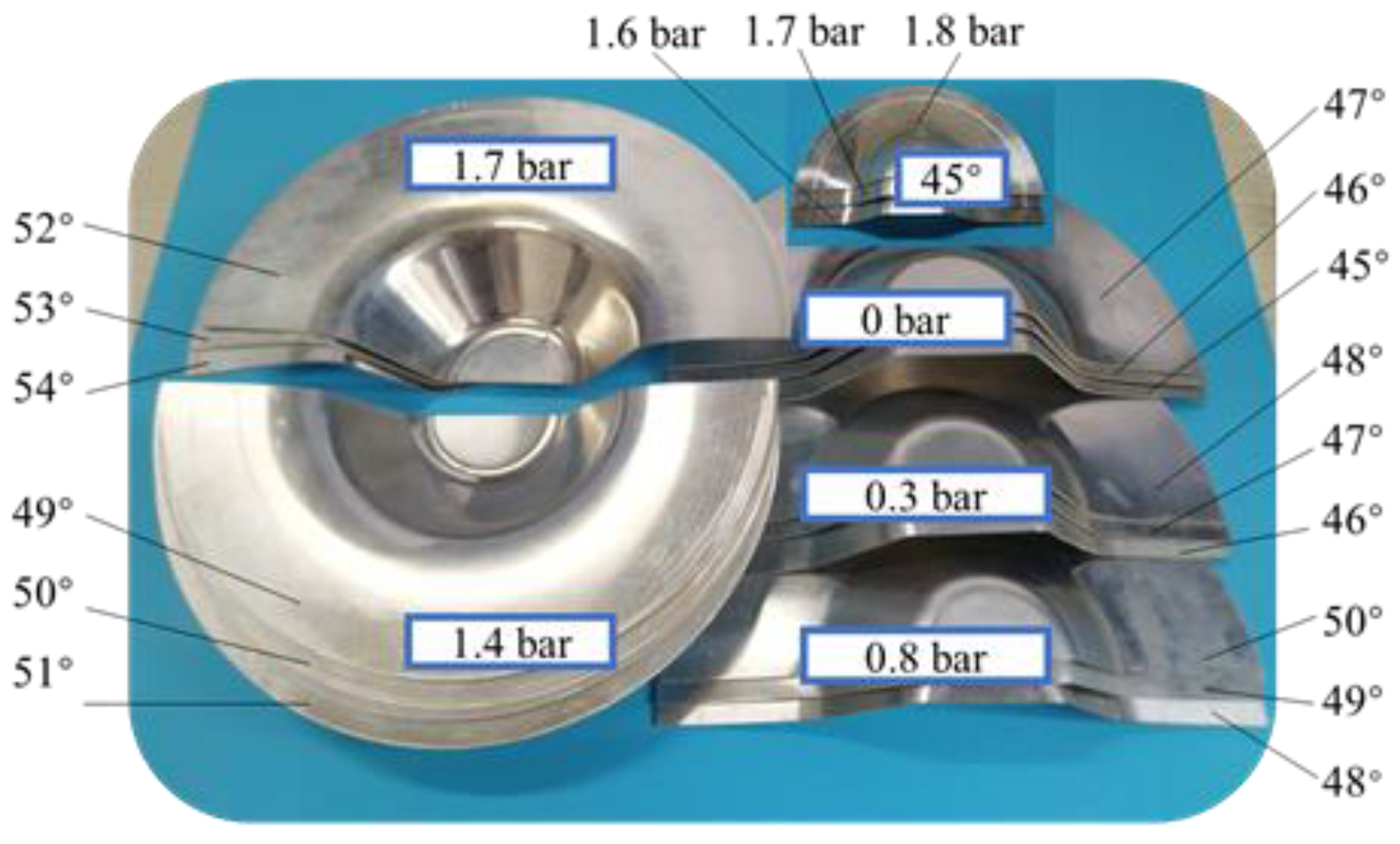
The hydraulic sheet metal incremental sheet forming process can effectively promote the uniform distribution of sheet metal wall thickness. In the range of 0 1.7   bar , with the pressure increase, the thinning zone gradually spreads in the main forming zone II, and the thickness distribution becomes more and more uniform. When the hydraulic pressure is 1.8 bar, the hydraulic support will hinder the uniform distribution of wall thickness in a few small local areas;
(2)
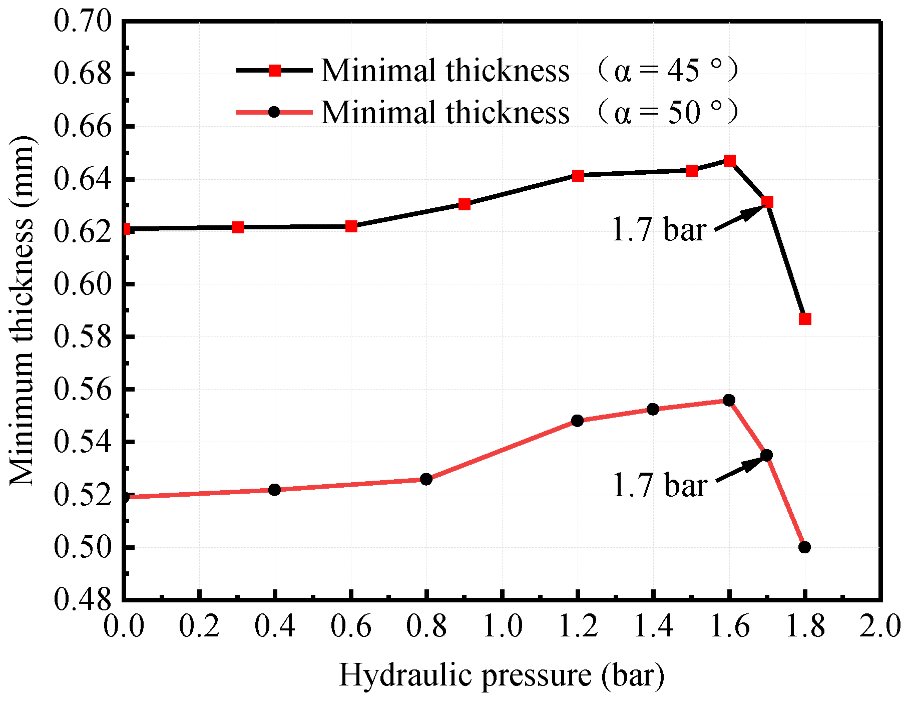
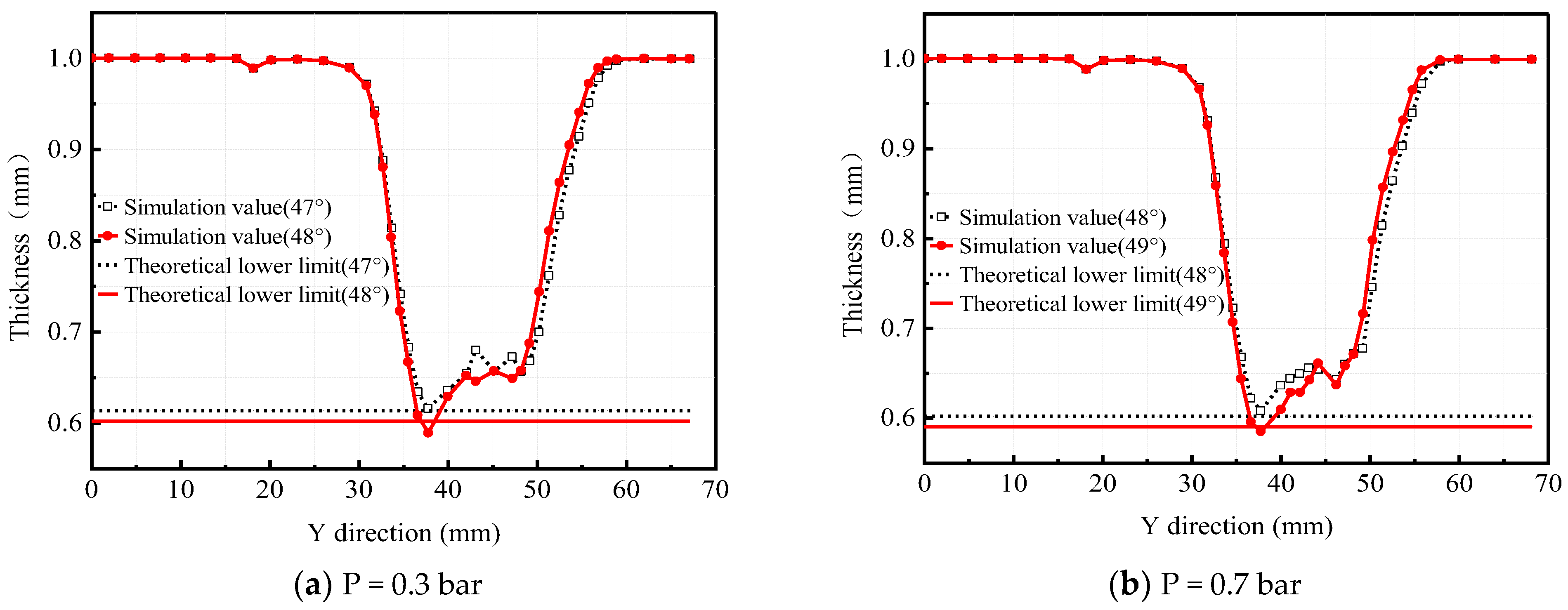
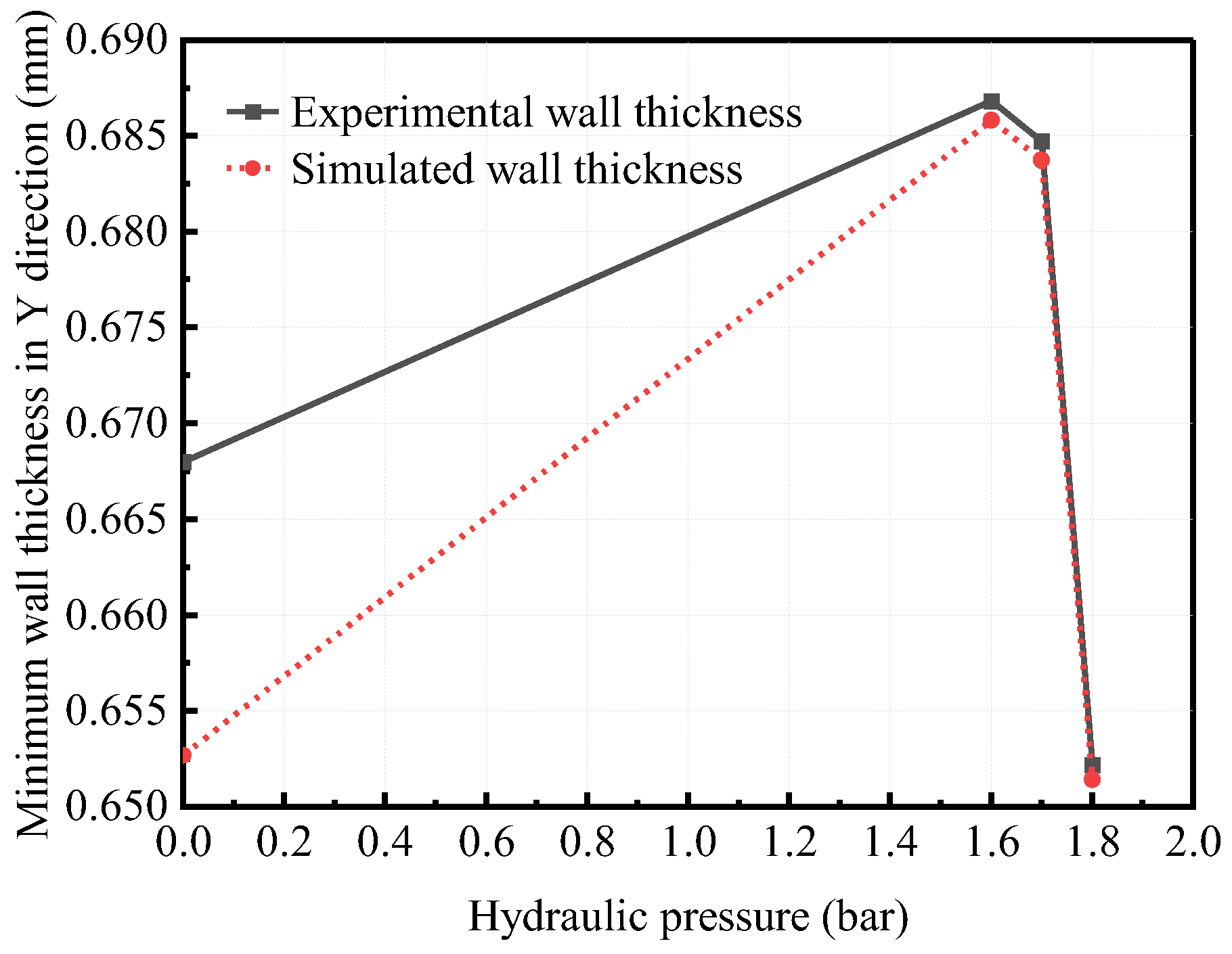
When forming truncated pyramid parts with different angles, the influence trend of hydraulic parameters on wall thickness distribution is consistent. With increased hydraulic pressure, the minimum wall thickness increases first and then decreases. The favorable pressure range of the HS-SPIF process for uniform distribution of wall thickness is 0 1.7   bar ;
(3)
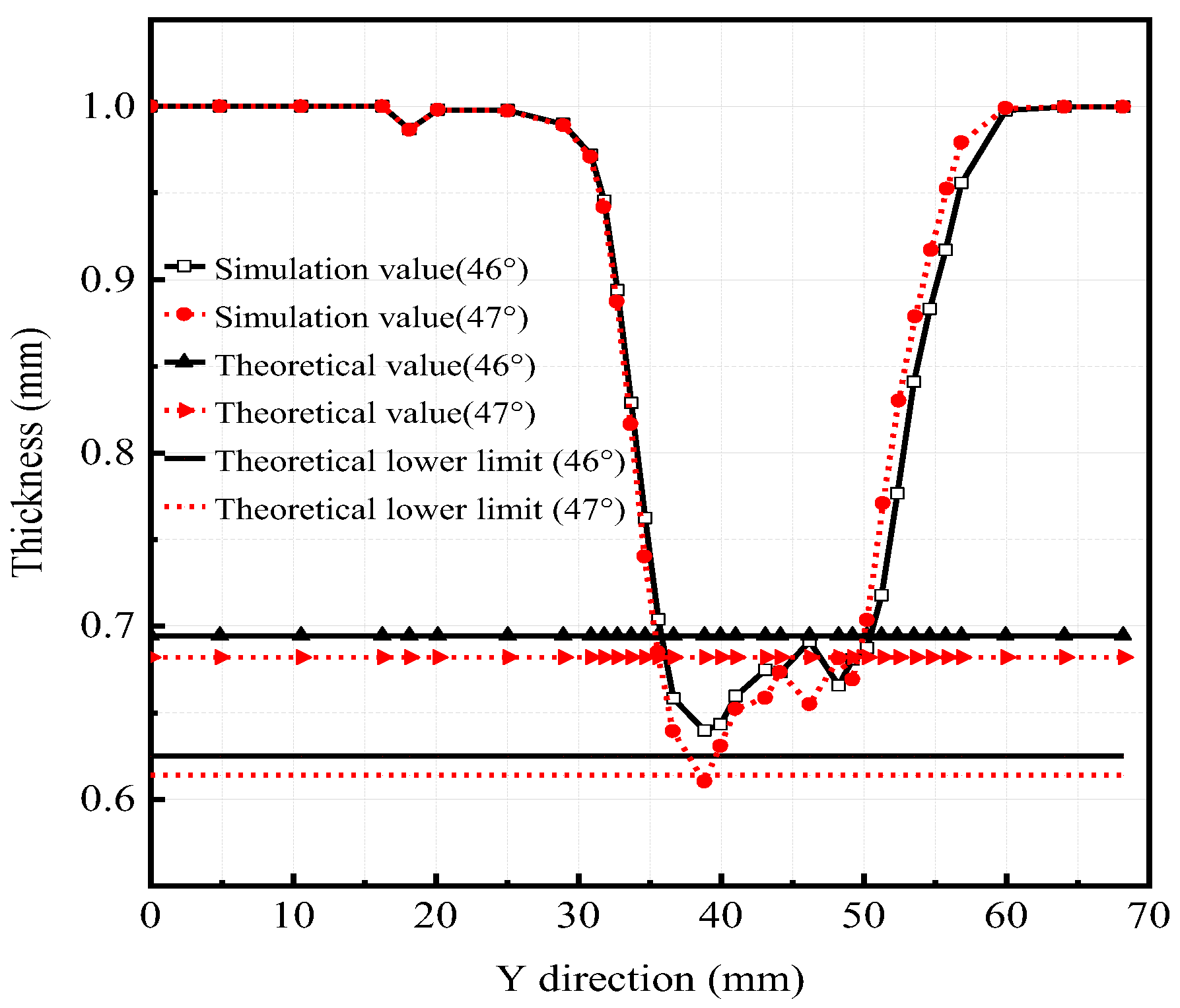
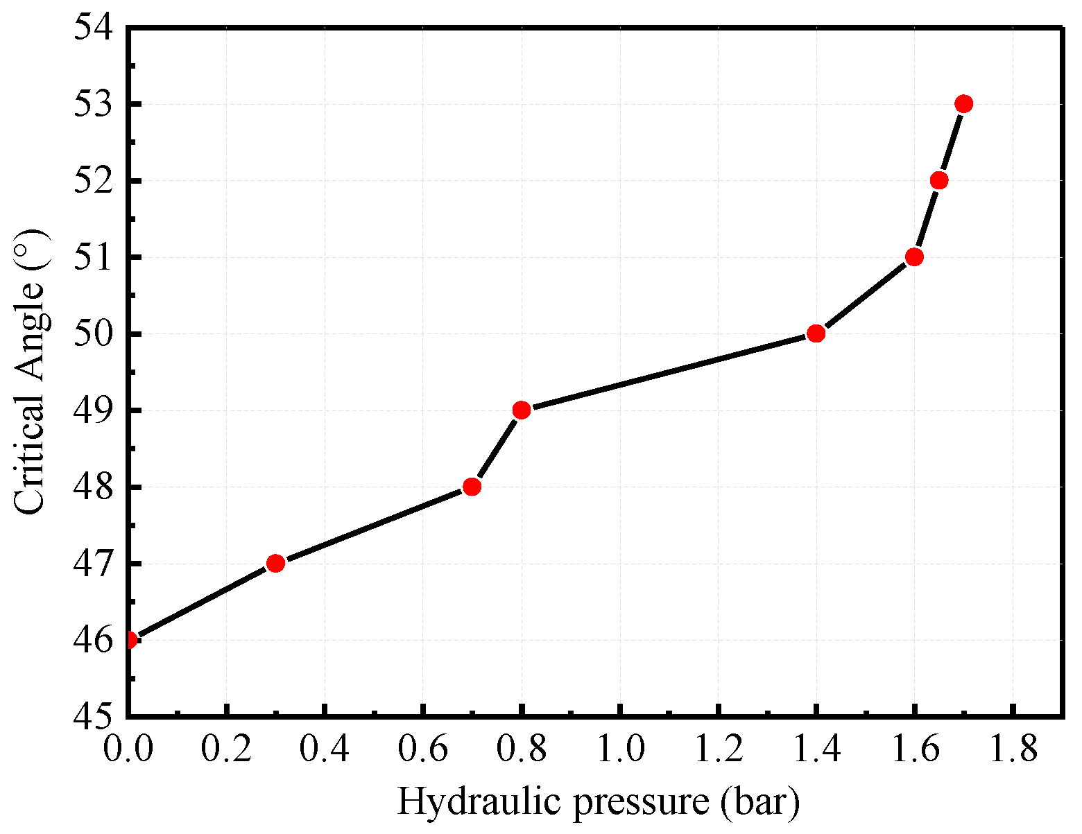
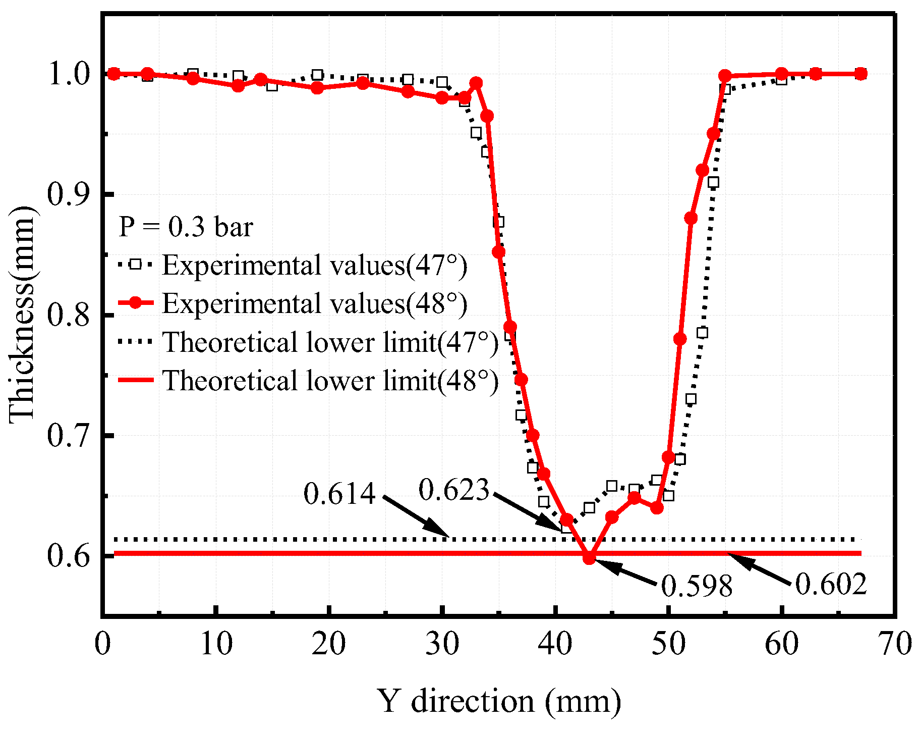
The HS-SPIF process is helpful in improving the uniform critical angle of wall thickness. When the hydraulic pressure is at 0 1.7   bar , the critical forming angle of HS-SPIF will increase with the pressure increase. When hydraulic pressure is used, the hydraulic pressure is the most sensitive to the critical forming angle. In the same other working conditions, the critical angle obtained by the ordinary SPIF process is 46°, while that obtained by the HS-SPIF process is 47 53 ° ;
(4)
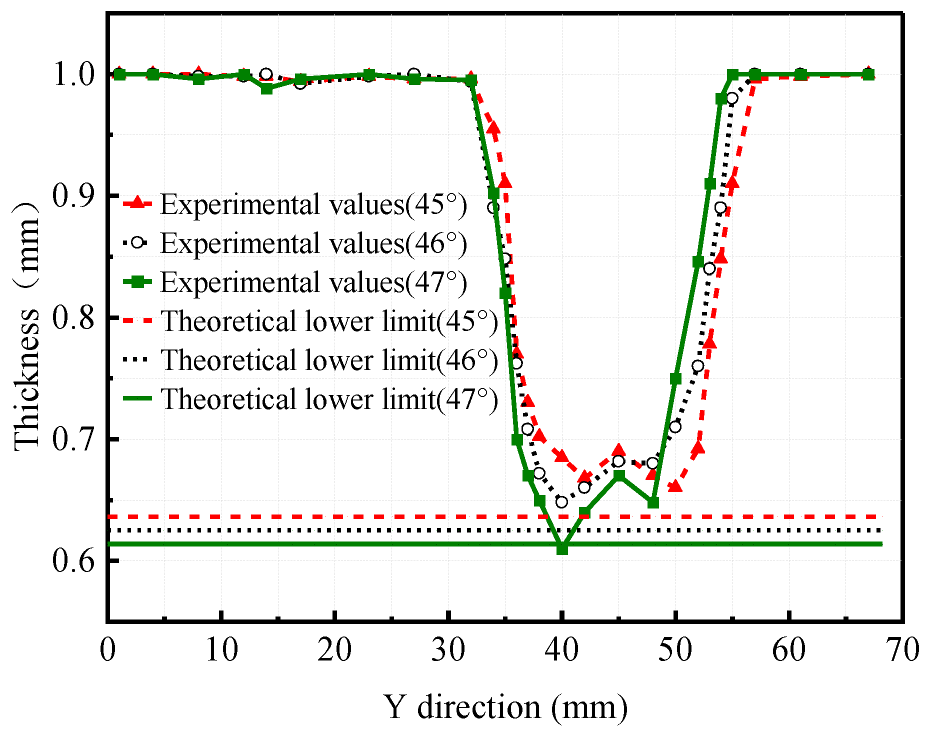
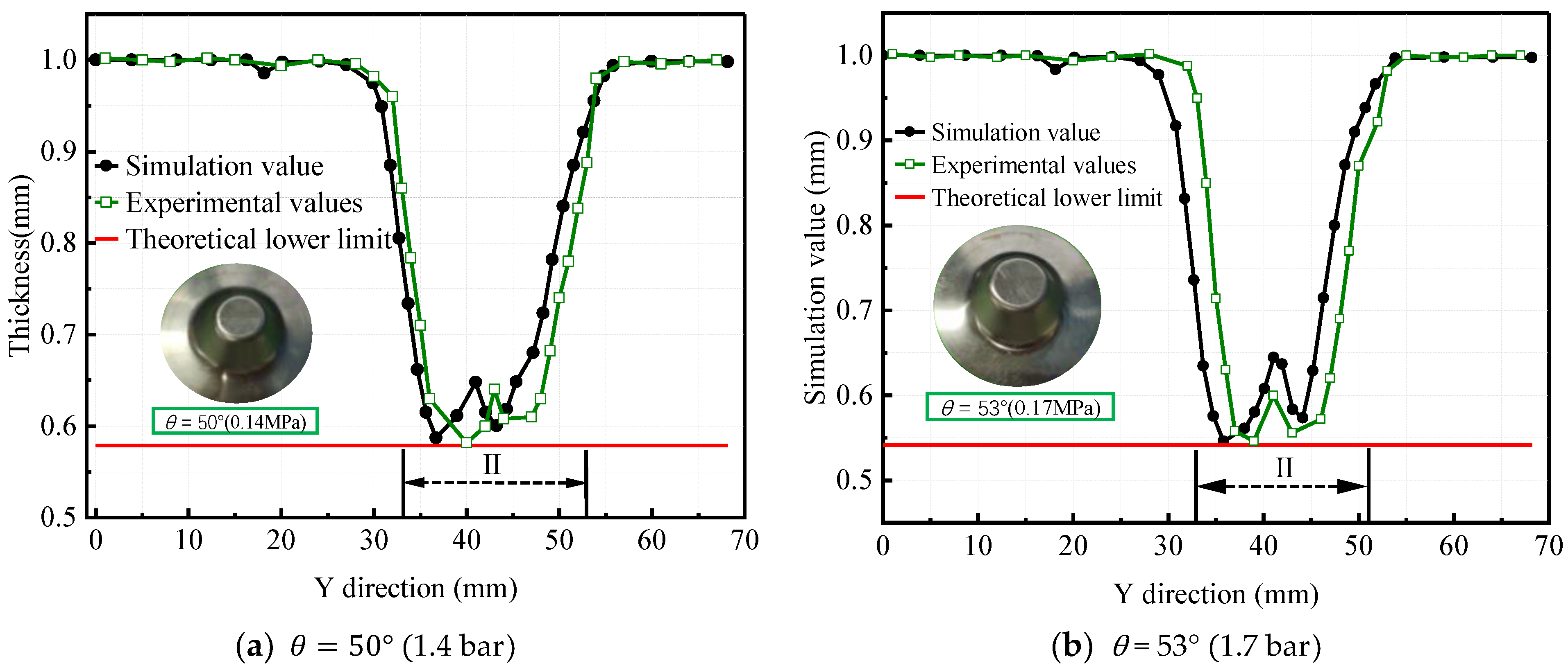
When the truncated pyramid with different forming angles is processed under different pressure, the most serious thinning part of the sheet is basically the same. Based on the assumption that there is only shear deformation, the occurrence of the minimum wall thickness of the experiment is 1.136–3.293 mm later than that of the finite element simulation, but these errors do not affect the determination of the final critical angle. As to the influence of hydraulic parameters on the uniform critical angle of wall thickness, the experimental results are consistent with the simulation results.

Author Contributions

Conceptualization, M.S. and Y.L.; methodology, Y.L.; software, L.B.; validation, M.S. and Y.C.; formal analysis, L.B.; investigation, M.S. and Y.C.; resources, Y.L. and P.L.; data curation, M.S. and Y.C.; writing—original draft preparation, M.S.; writing—review and editing, M.Y. and P.L.; supervision, M.S. and M.Y.; project administration, M.S.; funding acquisition, Y.L. and L.B. All authors have read and agreed to the published version of the manuscript.

Funding

This research was supported by the National Natural Science Foundation of China (Grant Number: 52075437), the Shaanxi Natural Science Basic Research Project (Grant Number: 2021JQ-794), and the Shaanxi Provincial Department of Education Special Scientific Research Project (Grant Number: 21JK0876).

Institutional Review Board Statement

Not applicable.

Informed Consent Statement

Not applicable.

Data Availability Statement

Data are contained within the article as figures and tables.

Conflicts of Interest

The authors declare no conflict of interest.

References

  1. Behera, A.K.; de Sousa, R.A.; Ingarao, G.; Oleksik, V. Single Point Incremental Forming: An Assessment of the Progress and Technology Trends From 2005 to 2015. J. Manuf. Process. 2017, 27, 37–62. [Google Scholar] [CrossRef] [Green Version]
  2. Li, P.Y.; He, J.; Liu, Q.; Yang, M.S.; Wang, Q.D.; Yuan, Q.L.; Li, Y. Evaluation of Forming Forces in Ultrasonic Incremental Sheet Metal Forming. Aerosp. Sci. Technol. 2017, 63, 132–139. [Google Scholar] [CrossRef] [Green Version]
  3. Liu, Z.B.; Daniel, W.; Li, Y.L.; Liu, S.; Meehan, P.A. Multi-Pass Deformation Design for Incremental Sheet Forming: Analytical Modeling, Finite Element Analysis and Experimental Validation. J. Mater. Process. Technol. 2014, 214, 620–634. [Google Scholar] [CrossRef] [Green Version]
  4. Vincze, G.; Pereira, A.B.; Lopes, D.; Yanez, J.; Butuc, M.C. Study on Asymmetric Rolling Process Applied to Aluminum Alloy Sheets. Machines 2022, 10, 641. [Google Scholar] [CrossRef]
  5. Liu, F.Y.; Li, Y.L.; Ghafoor, S.; Cheng, Z.N.; Li, F.Y.; Li, J.F. Sustainability Assessment of Incremental Sheet Forming: A Review. Int. J. Adv. Manuf. Technol. 2022, 119, 1385–1405. [Google Scholar] [CrossRef]
  6. Azaouzi, M.; Lebaal, N. Tool Path Optimization for Single Point Incremental Sheet Forming Using Response Surface Method. Simul. Model. Pract. Theory 2012, 24, 49–58. [Google Scholar] [CrossRef]
  7. Ben Said, L.; Mars, J.; Wali, M.; Dammak, F. Effects of the Tool Path Strategies on Incremental Sheet Metal Forming Process. Mech. Ind. 2016, 17, 411. [Google Scholar] [CrossRef]
  8. Nirala, H.K.; Agrawal, A. Fractal Geometry Rooted Incremental Toolpath for Incremental Sheet Forming. J. Manuf. Sci. Eng.-Trans. ASME 2018, 140, 021005. [Google Scholar] [CrossRef]
  9. Cao, T.T.; Lu, B.; Ou, H.G.; Long, H.; Chen, J. Investigation on a New Hole-Flanging Approach by Incremental Sheet Forming through a Featured Tool. Int. J. Mach. Tools Manuf. 2016, 110, 1–17. [Google Scholar] [CrossRef]
  10. Bouhamed, A.; Jrad, H.; Mars, J.; Wali, M.; Gamaoun, F.; Dammak, F. Homogenization of Elasto-Plastic Functionally Graded Material Based on Representative Volume Element: Application to Incremental Forming Process. Int. J. Mech. Sci. 2019, 160, 412–420. [Google Scholar] [CrossRef]
  11. Ben Said, L.; Mars, J.; Wali, M.; Dammak, F. Numerical Prediction of the Ductile Damage in Single Point Incremental Forming Process. Int. J. Mech. Sci. 2017, 131, 546–558. [Google Scholar] [CrossRef]
  12. Liu, Z.B.; Li, Y.L.; Meehan, P.A. Vertical Wall Formation and Material Flow Control for Incremental Sheet Forming by Revisiting Multistage Deformation Path Strategies. Mater. Manuf. Process. 2013, 28, 562–571. [Google Scholar] [CrossRef]
  13. Zhu, H.; Cheng, G.X.; Jung, D.W. Toolpath Planning and Generation for Multi-Stage Incremental Forming Based on Stretching Angle. Materials 2021, 14, 4818. [Google Scholar] [CrossRef] [PubMed]
  14. Mirnia, M.J.; Dariani, B.M.; Vanhove, H.; Duflou, J.R. Thickness Improvement in Single Point Incremental Forming Deduced by Sequential Limit Analysis. Int. J. Adv. Manuf. Technol. 2014, 70, 2029–2041. [Google Scholar] [CrossRef]
  15. Li, J.C.; Hu, J.B.; Pan, J.J.; Geng, P. Thickness Distribution and Design of a Multi-Stage Process for Sheet Metal Incremental Forming. Int. J. Adv. Manuf. Technol. 2012, 62, 981–988. [Google Scholar] [CrossRef]
  16. Ullah, S.; Li, X.Q.; Xu, P.; Li, D.S. Experimental and Numerical Investigation for Sheet Thickness Thinning in Two-Point Incremental Forming (Tpif). Int. J. Adv. Manuf. Technol. 2022, 122, 2493–2512. [Google Scholar] [CrossRef]
  17. Li, X.Q.; Han, K.; Xu, P.; Wang, H.B.; Li, D.S.; Li, Y.L.; Li, Q. Experimental and Theoretical Analysis of the Thickness Distribution in Multistage Two Point Incremental Sheet Forming. Int. J. Adv. Manuf. Technol. 2020, 107, 191–203. [Google Scholar] [CrossRef]
  18. Smith, J.; Malhotra, R.; Liu, W.K.; Cao, J. Deformation Mechanics in Single-Point and Accumulative Double-Sided Incremental Forming. Int. J. Adv. Manuf. Technol. 2013, 69, 1185–1201. [Google Scholar] [CrossRef]
  19. Praveen, K.; Shivaprasad, C.H.; Reddy, N.V. Effect of Support Force on Quality During Double-Sided Incremental Forming: An Experimental and Numerical Study. Int. J. Adv. Manuf. Technol. 2022, 122, 4275–4292. [Google Scholar] [CrossRef]
  20. Jin, Z.; Gao, J.; Zheng, L. Study on critical forming angle of progressive forming supported by punch of 1060 aluminum plate. Forg. Technol. 2022, 47, 99–106. [Google Scholar]
  21. Ben Khalifa, N.; Thiery, S. Incremental Sheet Forming with Active Medium. CIRP Ann.-Manuf. Technol. 2019, 68, 313–316. [Google Scholar] [CrossRef]
  22. Yu, J.H.; Jung, K.S.; Murugesan, M.; Chung, W.J.; Lee, C.W. Study on the Incremental Sheet Metal Forming Process Using a Metal Foam as a Die. Int. J. Mater. Form. 2022, 15, 71. [Google Scholar] [CrossRef]
  23. Kucukturk, G.; Yazgin, H.V. Improvement of Incremental Sheet Metal Forming with the Help of a Pressurised Fluid System. Mater. Test. 2022, 64, 1214–1222. [Google Scholar] [CrossRef]
  24. Hassan, A.A.; Kucukturk, G.; Yazgin, H.V.; Gurun, H.; Kaya, D. Selection of Constitutive Material Model for the Finite Element Simulation of Pressure-Assisted Single-Point Incremental Forming. Machines 2022, 10, 941. [Google Scholar] [CrossRef]
  25. Kumar, Y.; Kumar, S. Experimental and Analytical Evaluation of Incremental Sheet Hydro-Forming Strategies to Produce High Forming Angle Sheets. Heliyon 2019, 5, e01801. [Google Scholar] [CrossRef] [PubMed] [Green Version]
  26. Bai, L. Study on Single Point Incremental Forming Accuracy and Influence Mechanism of Static Pressure Support and Ultrasonic Vibration. Ph.D. Thesis, Xi’an University of Technology, Xi’an, China, 2019. Available online: https://kns.cnki.net/kcms/detail/detail.aspx.FileName=1020306279.nh&DbName=CDFD2021 (accessed on 2 March 2022).
  27. Shi, W.; Gao, J. Study on the uniform critical angle of wall thickness in progressive forming supported by the outer contour of 1060 aluminum plate convex table. Forg. Technol. 2019, 44, 27–33. [Google Scholar]
  28. Ghorbel, O.; Koubaa, S.; Mars, J.; Wali, M.; Dammak, F. Non Associated-Anisotropic Plasticity Model Fully Coupled with Isotropic Ductile Damage for Sheet Metal Forming Applications. Int. J. Solids Struct. 2019, 166, 96–111. [Google Scholar] [CrossRef]
  29. Bouhamed, A.; Jrad, H.; Ben Said, L.; Wali, M.; Dammak, F. A Non-Associated Anisotropic Plasticity Model with Mixed Isotropic-Kinematic Hardening for Finite Element Simulation of Incremental Sheet Metal Forming Process. Int. J. Adv. Manuf. Technol. 2019, 100, 929–940. [Google Scholar] [CrossRef]
  30. Yang, M.S.; Xiao, X.D.; Yao, Z.Y.; Yuan, Q.L. Study on the limit of single-point incremental forming of ultrasonic vibration of 1060 aluminum plate. J. Ordnance Ind. 2019, 40, 601–611. [Google Scholar]
Figure 1. HS-SPIF principle diagram.
Machines 11 00353 g001
Figure 2. Schematic diagram of wall thickness changes.
Machines 11 00353 g002
Figure 3. Simplified FE modeling for HS-SPIF.
Machines 11 00353 g003
Figure 4. Final shape of simulation.
Machines 11 00353 g004
Figure 5. True stress-strain curve of Al 1060 sheet.
Machines 11 00353 g005
Figure 6. Tool path for a truncated pyramid.
Machines 11 00353 g006
Figure 7. The experimental system used for HS-SPIF.
Machines 11 00353 g007
Figure 8. Cloud map of thickness distribution under different hydraulic parameters (45°).
Machines 11 00353 g008
Figure 9. Thickness distribution in Y direction.
Machines 11 00353 g009
Figure 10. Simulated and theoretical contours.
Machines 11 00353 g010
Figure 11. Axial error under different hydraulic parameters.
Machines 11 00353 g011
Figure 12. Cloud map of thickness distribution under different hydraulic parameters (α = 50°).
Machines 11 00353 g012aMachines 11 00353 g012b
Figure 13. Thickness distribution in the main forming zone II of Y direction (α = 50°).
Machines 11 00353 g013
Figure 14. Plastic strain component εz along the Y direction under different pressures.
Machines 11 00353 g014
Figure 15. Minimum wall thickness under various hydraulic parameters.
Machines 11 00353 g015
Figure 16. SPIF Simulated Wall Thickness Distribution ( α = 48 ° ).
Machines 11 00353 g016
Figure 17. SPIF simulates wall thickness distribution ( α = 46 ° and α = 47°).
Machines 11 00353 g017
Figure 18. Simulated wall thickness distribution of HS-SPIF under different pressures.
Machines 11 00353 g018
Figure 19. The curve of the critical angle varies with hydraulic parameters.
Machines 11 00353 g019
Figure 20. Half-section of cutting specimen.
Machines 11 00353 g020
Figure 21. Measuring tool.
Machines 11 00353 g021
Figure 22. Minimum wall thickness for different hydraulic parameters in the Y direction.
Machines 11 00353 g022
Figure 23. SPIF experimental wall thickness distribution.
Machines 11 00353 g023
Figure 24. HS-SPIF experimental wall thickness distribution.
Machines 11 00353 g024
Figure 25. HS-SPIF critical angle wall thickness distribution.
Machines 11 00353 g025
Table 1. Material properties of Al 1060 aluminum alloy sheets.
MaterialAl 1060
Density (t/mm3)2.71 × 10−9
Young’s modulus (MPa)68,000
Poisson’s ratio0.33
Yield strength (MPa)138
Tensile strength (MPa)145
Plastic coefficient K758.60
Hardening exponent n0.31
Table 2. The equipment of the HS-SPIF experimental system.
Experimental EquipmentDescription
Forming deviceThe forming device includes the tool head and the MVC510 vertical CNC machine tool produced by Qinchuan Machine Tool Factory in China
Hydraulic systemThe hydraulic system includes a fuel tank, hydraulic pump, pressure gauge, relief valve, one-way valve, and sealing ring
Sheet fixtureThe sheet fixture is composed of an upper-pressing sheet and a lower-pressing sheet, which is used to fix the sheet
Oil cavityThe oil cavity and the lower pressure sheet are whole, which can be used to fix and support the sheet as well as for the storage of hydraulic oil so as to realize the change of the support pressure on the lower surface of the sheet
WEDM machineWEDM machine generated by Sanguang Company, used for cutting formed parts
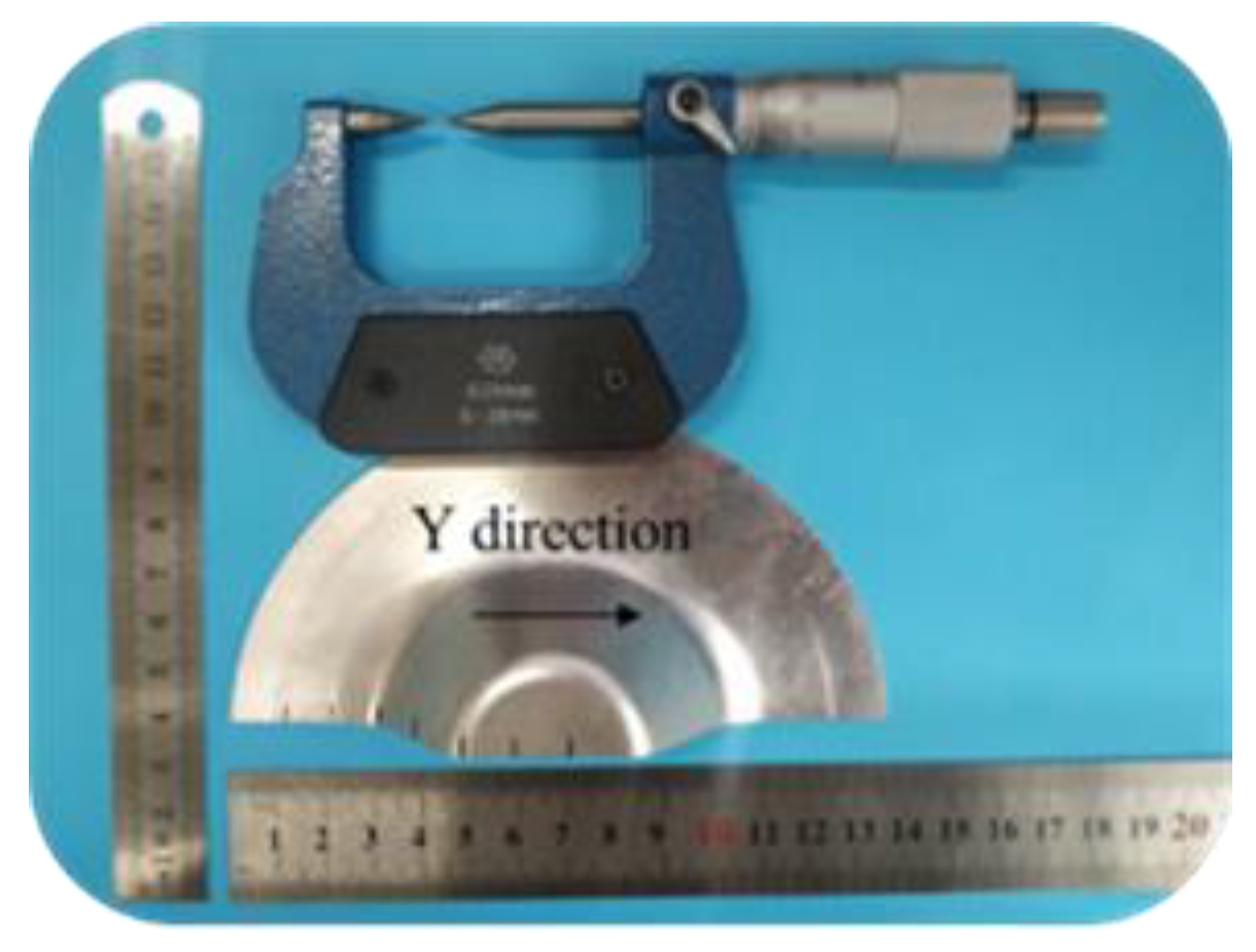
Double-pointed spiral
micrometer
It is used to measure the wall thickness
Table 3. Parameters of simulated critical angles.
Pressure
(bar)
Forming
Angle
(°)
Minimum
Thickness of Y
Direction
(mm)
Theoretical Minimum Thickness (mm)Node NumberY Direction
Distance
(mm)
Critical   Angle   of   Simulation   ( ° )
0460.63976 0.62519 4138.834 46°
470.61012 0.61380 4138.864
0.3 470.61623 0.61380 4037.721 47°
480.58929 0.60222 4037.774
0.7 480.60225 0.60222 4037.741 48°
490.58520 0.59045 4037.737
0.8 490.59379 0.59045 4037.737 49°
500.56824 0.57870 4037.770
1.4 500.58691 0.57870 3936.706 50°
510.55863 0.56639 3936.742
1.6 510.56846 0.56639 3936.795 51°
520.55228 0.55409 3936.772
1.65 520.555690.55409 3936.85552°
530.537050.54164 3835.750
1.7530.54252 0.54164 3835.786 53°
540.50821 0.52900 3835.776
Table 4. Experimental verification scheme and parameters.
Pressure
(Bar)
Forming Angle (°)Initial Sheet Thickness (mm)Theoretical Minimum Thickness (mm)
1.6451.002-
1.7451.004-
1.8451.002-
0451.0020.636
461.0060.625
471.0050.614
0.3461.0020.625
471.0040.614
481.0020.602
0.8481.0020.602
491.0040.590
501.0040.579
1.4491.0020.590
501.0020.579
511.0040.566
1.7521.0020.554
531.0020.542
541.0040.529
Disclaimer/Publisher’s Note: The statements, opinions and data contained in all publications are solely those of the individual author(s) and contributor(s) and not of MDPI and/or the editor(s). MDPI and/or the editor(s) disclaim responsibility for any injury to people or property resulting from any ideas, methods, instructions or products referred to in the content.

