Article

Lubrication Mechanism of scCO2-MQL in the Assisted Machining of Titanium Alloys

1
College of Mechanical and Power Engineering, Harbin University of Science and Technology, Harbin 150080, China
2
School of Mechanical Engineering and Rail Transit, Changzhou University, Changzhou 213164, China
*
Author to whom correspondence should be addressed.
Machines 2023, 11(2), 291; https://doi.org/10.3390/machines11020291
Submission received: 12 December 2022 / Revised: 11 February 2023 / Accepted: 13 February 2023 / Published: 15 February 2023
(This article belongs to the Special Issue Recent Progress of Thin Wall Machining)

Abstract

:
Cutting fluids are often used in the machining of titanium alloys to reduce processing temperature and maximize quality and productivity. The permeability of the cutting fluid in the capillary tube directly influences the effect of lubrication on cooling performance. In this study, supercritical carbon dioxide cryogenic micro-lubrication (scCO2-MQL) is used for the auxiliary machining of titanium alloys. A capillary model for scCO2-MQL-assisted cutting is proposed and established while considering the characteristics of three-phase states produced during the decompression release of scCO2. The injection temperature and characteristics of scCO2 are experimentally investigated, and the dynamic process of scCO2-MQL penetration into the capillary is analyzed. The results show that under the applied experimental conditions, the injection temperature of scCO2-MQL ranges from approximately −45 °C to 60 °C. Because scCO2 presents good solubility in oil, it has the capacity to refine the oil droplets into smaller particles, thus resulting in a higher lubricating oil content in the capillary per unit of time. This leads to enhanced lubricity that can benefit processing applications.

1. Introduction

In the process of machining titanium alloys, increased cutting force and heat often occur because of the limited thermal conductivity of these materials. This leads to the deterioration of surface integrity and tool wear [1,2], thus limiting the productivity and quality of titanium alloy processing. Cutting fluids are frequently used in the machining process to address this problem. The selection of a suitable cutting fluid can effectively reduce cutting temperature, lengthen tool life, and increase production efficiency and machining surface quality [3,4,5].
To prevent the environmental pollution caused by cutting fluids, green processing methods, such as liquid nitrogen, cryogenic air, and micro-lubrication, are commonly employed in the processing of titanium alloys. Supercritical carbon dioxide minimum quantity lubrication (scCO2-MQL) is a cryogenic technology that was proposed in 2006; herein, carbon dioxide is in a supercritical state when its temperature is above 31.2 °C and its pressure is above 7.38 MPa. In this case, it can dissolve oils and lipids, and carry specific cutting fluids in the liquid [6]. When CO2 is sprayed from a supercritical state to atmospheric pressure, a certain number of dry ice particles are generated. Because the temperature of dry ice particles is approximately −78 °C [7], a cryogenic region can be formed within a particular range. Compared with other cryogenic cutting technologies, such as liquid nitrogen, scCO2-MQL not only fulfills the cooling effect required in machining but also minimizes friction in the cutting area through a lubricating oil. Moreover, the critical state of scCO2 is easily achievable, and, therefore, it presents the benefits of simple preparation, convenient transit, and comfortable operation. Thus, the use of scCO2-MQL as a cutting fluid is a superior choice for machining applications.
In recent years, various domestic and international scholars have conducted studies on the application of scCO2-MQL to machining. An et al. [8] performed dry cutting and comparative experiments, wherein Ti6Al4V was side-milled using scCO2 (supercritical carbon dioxide), scCO2-WMQL (scCO2 with antifreeze water-based minimum quantity lubrication), and scCO2-OoWMQL (scCO2 with oil-on-water-based MQL). They found that the VB (flank wear width) of scCO2-OoWMQL decreased by 67.2% compared with that of scCO2 alone. Tool wear is relatively mild when scCO2-WMQL and scCO2-OoWMQL are employed because of the reduced tool–chip friction of the MQL. Stephenson et al. [6] conducted a comparative test between scCO2-MQL and aqueous flood coolant and found that the degree of tool wear was lower when machining with scCO2-MQL liquid. In turning Ti6Al4V, Bagherzadeh et al. [9,10] discovered that scCO2-MQL provided increased tool life, greater surface integrity, and lower cutting temperatures than scCO2 alone. When 316 L stainless steel was milled, scCO2-MQL reduced the tool flank wear by 32%. Rahim et al. [11] reported that compared with conventional micro-lubrication technology, using scCO2-MQL as a cooling lubricant led to a reduction in cutting temperature of approximately 15–30% and in cutting force of 5–14%. Litwa et al. [12] studied the effect of cutting conditions on the surface integrity of Ti-6Al-4V milling using various cooling methods and discovered that supercritical carbon dioxide improved the surface integrity of Ti-6Al-4V ball milling applications with high feeds. Cai et al. [13] analyzed the cutting force, cutting temperature, surface morphology, and surface roughness of processing through comparative experiments. The results revealed that the minimum cutting force and its coefficient were obtained in an scCO2-OoWMQL environment because of its excellent cooling/lubrication and chip removal performance.
During the cutting process, a cutting fluid permeates into the cutting zone through the capillary, and adsorption or chemical reactions occur on the contact surface between the tool, chip, and workpiece, thereby forming a film that produces lubrication. Williams et al. [14] and Godleviski [15] predicted and hypothesized a capillary model for this process. Using cutting tests on transparent plexiglass, Liu et al. [16] observed the capillary process phenomenon of cutting fluid permeating the cutting zone for the first time and analyzed the kinetic and kinematic processes of water vapor permeation into the capillary. Wang et al. [17] proposed an analysis model to evaluate the flank face cutting area after metalworking-fluid infiltration based on the Navier–Stokes and modified Reynolds lubrication equations. Reportedly, scCO2-MQL could completely infiltrate the tool-workpiece contact area.
The aforementioned studies explored the process of single- and two-phase cutting fluids, such as gaseous, liquid, and micro-lubrication, which penetrate the cutting zone. However, the influence of three-phase lubrication on the cutting zone and the formation mechanism for lubrication have not been studied. In this study, the lubrication mechanism for the scCO2-MQL-assisted machining of titanium alloys was investigated with respect to the properties of three phases formed during the injection process of scCO2-MQL.

2. Materials and Methods

2.1. Hypothesis of the Capillary Model

Capillary hypothesis theory states that a certain surface roughness value exists between the tool rake face and the bottom surface of the chip. Moreover, the theory indicates that because of a steady decrease in the normal and shear stresses in a tool–chip contact sliding zone, small gaps exist on a tool–chip contact surface. The capillary model is a simplified model of these microscopic gaps. Here, the tool–chip contact region was separated into bonding and sliding areas. The length of the bonding area was approximately 1/2–2/3 of the length of the tool–chip contact area, and the rest was the sliding area, as shown in Figure 1.
Under the experimental conditions used in this study, the scCO2 pressure was approximately 8 MPa and the temperature was approximately 40 °C. The external atmospheric pressure was approximately 0.101325 MPa and the temperature was approximately 20 °C. Therefore, in the process of supercritical fluid ejection from the nozzle, the significant pressure difference and temperature differential between the interior and external environments of the cryogenic cooling equipment ensured that the scCO2 pressure decreased rapidly after ejection from the nozzle. The phase diagram for carbon dioxide shown in Figure 2 indicates that in the process of scCO2-MQL decompression and cooling, three phases of gas, liquid, and solid are generated. This is described in more detail in Figure 3.
During decompression, scCO2-MQL produces carbon dioxide in a cold-temperature state, such as dry ice particles, and forms a cryogenic region in the cutting zone. Because the temperature of dry ice particles is approximately −78 °C, which is much lower than the temperature of the cutting zone, dry ice particles and cryogenic carbon dioxide induce heat exchange during the machining process. Dry ice particles and cryogenic carbon dioxide absorb the heat of the cutting zone, from solid and liquid to gaseous carbon dioxide, which further reduces the temperature of the cutting zone. In addition, because the cutting zone is not at a high temperature at the beginning of the cutting process, with the continuous injection of supercritical carbon dioxide fluid, dry ice particles may not sublimate into a gaseous state in the cutting zone in time because the temperature does not reach its sublimation point. For a continuous cutting process, a significant extrusion and scratching impact occurs between the tool and chip, which may increase under the interference of dry ice particles, thereby altering the development of capillaries in the cutting area.

2.2. Establishment of the Capillary Model

Dry ice particles were analyzed by considering their effect on the cutting area, and the fact that the jet had a certain angle when scCO2-MQL was injected into the cutting area. A contact analysis between dry ice particles and the tool-workpiece is shown in Figure 4. The angle between the tool and horizontal plane was α, the angle between the chip and vertical plane was β, and the dry ice particle shape was assumed to be that of a circle. The angle of the knife–chip contact area may then be expressed as: 90° − α − β.
Dry ice particles are believed to have a specific scratching impact that acts between the tool–chip and workpiece during machining, which is indicated by the angle φ, and the dry ice particles are round. By solving for the final contact length of dry ice particles in contact with the object, its influence on final capillary formation may be obtained. The capillary formation analysis model is shown in Figure 5, where r represents the radius of dry ice particles.
In this case,
O C = r tan ( 1 2 θ )
B C = O C · tan φ = r tan φ tan ( 1 2 θ )
A B = r B C = r r tan φ tan ( 1 2 θ )
O B = ( O C 2 + B C 2 ) 1 2 = r tan ( 1 2 θ ) · ( tan φ ) 2 + 1 1 2
The values of A B D , D A C , and O A D can be determined using the expressions below, and DB can be calculated using the cosine formula, as follows.
A B D = 90 + φ
D A C = arccos ( A B 2 + r 2 D B 2 2 r · A B )
According to the arc length formula:
l 1 = r · D A C
O A D = arccos ( O A 2 + r 2 O D 2 2 r · O A )
According to
A D C = 1 2 θ φ + O A D
cos A D C = r 2 + D B 2 A B 2 2 r D B = D E 2 r
We obtained
D E = r 2 + D B 2 A B 2 D B
B E = D E D B
C A E = arccos ( A B 2 + r 2 B E 2 2 r A B )
and
l 2 = r C A E
The arc length of the line segment in the contact area of the dry ice particles was
l = l 1 + l 2 = r ( D A C + C A E )
Equations (3), (7) and (11)–(13) are introduced into Equation (16) and yielded:
l = r arccos r 2 1 tan φ tan 1 2 θ 2 + 1 D B 2 2 r 2 1 tan φ tan 1 2 θ + arccos 1 tan φ tan ( 1 2 θ ) D B 2 r 2 1 tan φ tan ( 1 2 θ ) 3 2 + D B 2 r 2 2 1 tan φ tan ( 1 2 θ ) + r 2 1 tan φ tan ( 1 2 θ )
This analysis indicates that DB is a known quantity that can be determined using the cosine formula. Therefore, the arc length l is only related to the values of r, θ, and φ.
As shown in Figure 6, A B D is equal to A E D because in triangle ADE, AD and AE have the same length and radius r.
Evidently from Figure 6,
D A C + B A H + A D B = 90 °
E A H + A E H = 90 °
and
E A H = E A B B A H
Therefore,
E A B B A H + A E H = 90 °
From the above analysis, A B D is equal to A E D , and therefore, E A B is greater than C A D . Thus, arc length l1 is shorter than arc length l2. As OC and AC are always vertical when φ is less than ½ of θ, regardless of changes in φ and θ, D A C is always smaller than C A E . Essentially, arc length l1 is always shorter than arc length l2.
If a period of time Δt is used in the analysis, the vaporization radius of the dry ice particles in this interval gradually decreases because of the constant pressure in the tool-chip contact area, as shown in Figure 7a. Because the interface of any sphere is circular, the top view of the capillary tube can be obtained under the condition that the extrusion coefficient generated between the dry ice particles and metal material is given an angle φ, L ( x ) represents the expression of the capillary profile equation, as shown in Figure 7b.
The length of the capillary tube can be expressed by the arc length as:
L = L 1 + L 2 + L 3 + + L n
where L is the contact length of each dry ice particle on the side of the chip contact area and n is the number of dry ice particles.
Han et al. [18] reported that the values of normal and shear stress steadily drop from the bonding zone to the sliding zone. Thus, an increase in the gap is proportional to the decrease in stress. When a cutting fluid is present in the gap, the radius of the dry ice particles gradually decreases, although its force is larger than that of the dry ice particles when the cutting fluid barely enters the tool–chip contact area. The influence of stress distribution on dry ice particles and capillary formation can also be directly determined by the angle φ of the aforementioned extrusion coefficient. The thin green lines in the picture are auxiliary lines, and the red lines indicate the degree of extrusion of dry ice particles in the process of tool and chip extrusion. As the cutting fluid penetrates the tool–chip contact zone, the angle φ gradually increases and the radius of the dry ice particles gradually decreases. Connect the intersection of dry ice particles and angle extension line at different angles to get the partial outline of the capillary shape, the border form of the capillary cross-section is depicted in Figure 8.
Combined with the above analysis of capillary top and profile views, the capillary model formed in this study using scCO2-MQL gradually decreased in width and gradually increased in depth along the direction passing from the sliding zone to the bonding zone. A three-dimensional view of this process is shown in Figure 9. The gray shadow part represents the object in which the capillary exists, and the yellow shadow part represents the actual image of the capillary, because the capillary was actually hollow, so the top of the image is not closed so that the shape of the bottom of the capillary can be seen. The yellow diagonal shadow part represents the capillary wall. The image on the left in Figure 9 can clearly show the indentation depth of the capillary under positive pressure.

3. Experiment Details

3.1. Laboratory Equipment

Figure 10 shows a schematic for the scCO2-MQL cooling system. Several parameters determined the cooling effect of scCO2-MQL. In this cooling device, the pressure of the scCO2-MQL was fixed at approximately 8 MPa. Controllable factors included the lubricating oil content, nozzle diameter, and injection distance. Therefore, the scCO2-MQL cooling temperature measurements were performed for these three variables.
The temperature of scCO2-MQL sprayed onto the γ-TiAl alloy sheet was measured. The armored thermal resistance model employed in the experiment was WZP-020, the specification was Φ5 × 20 × 2000 mm, and the graduation number was PT100. The temperature measurement equipment is depicted in Figure 11.
To measure the temperature at which supercritical carbon dioxide is injected into the alloy plate, holes were first drilled into the alloy plate to install the temperature measuring device. Figure 12 shows the dimensions of the alloy plate and holes. The size of γ-TiAl alloy was 150 × 150 × 30 mm and the size of the hole was 5.2 mm. The physical picture of the plate to be measured is shown in Figure 13. The temperature measurement resistance was placed in the hole, and the temperature value of scCO2-MQL ejection to the plate under different conditions was measured by thermal resistance probe.

3.2. Experimental Scheme

According to the experimental settings employed, the primary factors that impacted plate temperature were nozzle diameter, injection distance, and lubricating oil content in the scCO2-MQL. An orthogonal experiment was conducted to determine the primary and secondary relationships between several factors that influenced temperature after scCO2-MQL spraying. Through a range analysis of the data following the test, the level and optimal combination of influencing factors within the scope of this experiment were obtained. The experimental results are listed in Table 1.
The pictures shown in Figure 14 were used to conduct the injection experiment. The cooling temperature measurement experiment was conducted according to the orthogonal test design strategy. The temperature probe was placed in the hole of the alloy plate. When the supercritical carbon dioxide micro-lubrication cutting fluid was sprayed on the plate, the temperature of the plate using supercritical carbon dioxide micro-lubrication could be obtained by the temperature measuring probe. The results are displayed in Table 2.

4. Results

4.1. Injection Effect Analysis of scCO2-MQL

During the cutting process, different cutting parameters have varying effects on cooling. Therefore, to improve the efficiency of machining processes, an orthogonal experiment with three factors and three levels was used to study the primary and secondary orders of the scCO2-MQL cooling effect. Different nozzle diameters, lubricating oil contents, and injection distances were considered to determine the best combination of cooling parameters.
The cooling temperature measurement experiment was conducted according to the orthogonal test design strategy, and the results are displayed in Table 2.
The optimal level and best combination of factors that impacted the final temperature can be determined by comparing the range R values for various factors. The greater the range R, the larger the numerical change in the influencing factor in the test range, which leads to a greater change in the temperature value obtained for a test. Therefore, the larger the R value, the greater the effect of the influencing factor on the temperature value, and the more important the influencing factor.
Table 3 indicates that the ordering of factors from high to low R value was: nozzle diameter > injection distance > lubricating oil flow rate. Therefore, under the experimental settings employed, the most crucial factor affecting final plate temperature was the nozzle diameter, followed by the injection distance. The lubricating oil concentration in scCO2-MQL had the least influence on the temperature.
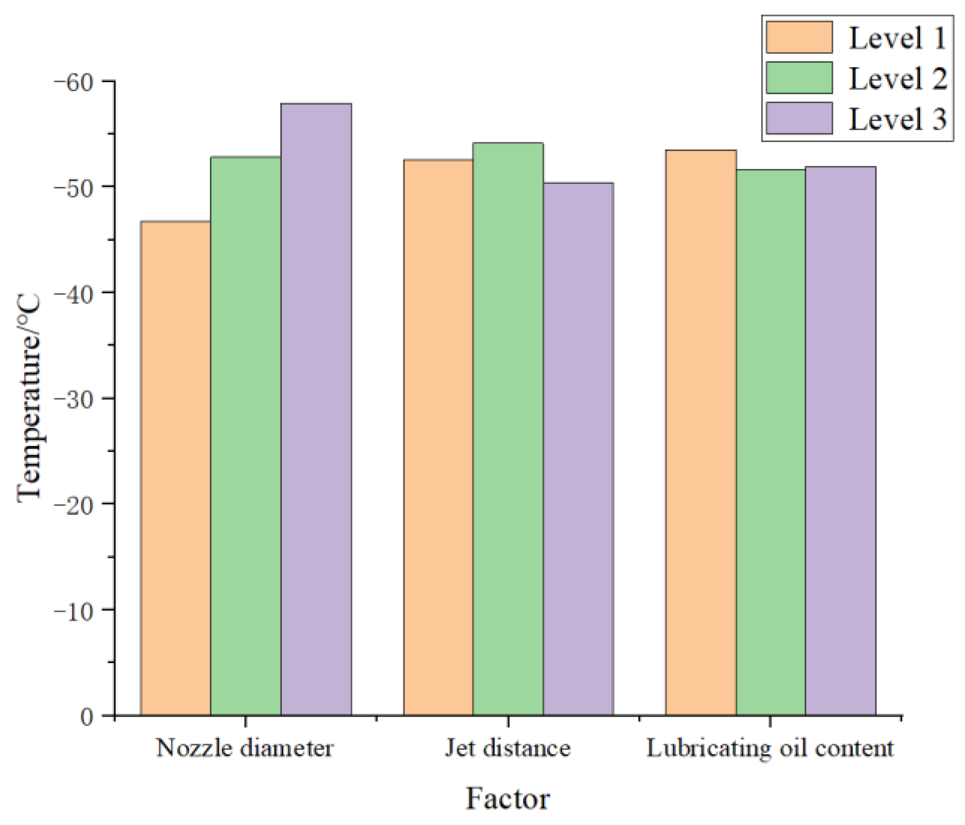
Histograms for temperature values measured under different influencing circumstances are shown in Figure 15. Evidently, a better cooling effect was obtained when using a nozzle diameter of level 3, injection distance of level 2, and lubricating oil content of level 1. This corresponded to an optimal combination under these experimental conditions of a nozzle diameter of 0.72 mm, injection distance of 40 mm, and lubricating oil content of 25 mL/h. In addition, the temperature values obtained at different lubricating oil content levels under these testing conditions did not differ considerably. This may have been because the limiting of experimental settings narrowed the range of lubricating oil content, and differences between the lubricating oil content data values at different levels were small.

4.2. Injection Structure Analysis for scCO2-MQL

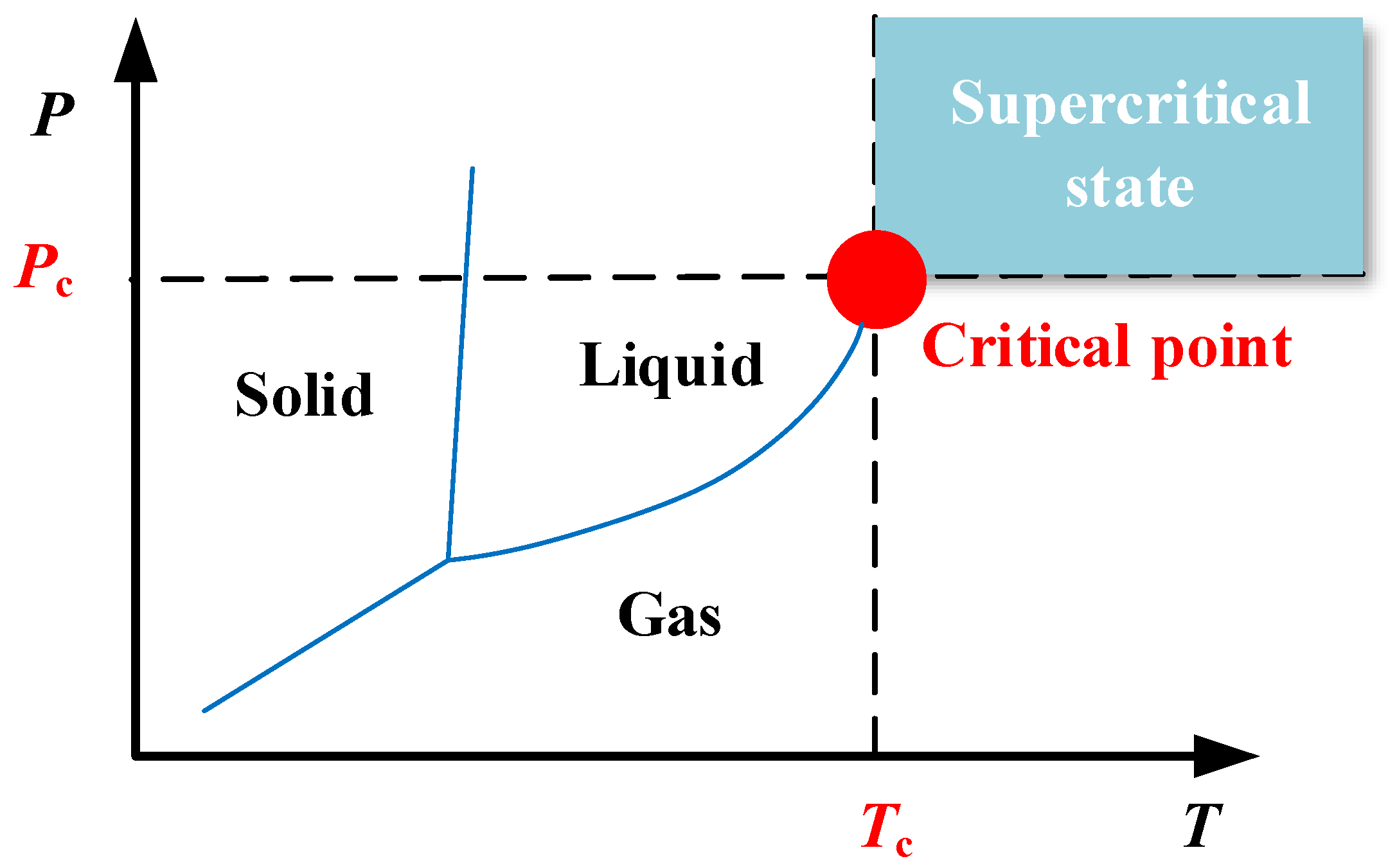
At a particular speed and pressure during the cutting process, the scCO2 jet entered the cutting zone, and it created phase shifts on exiting the tube. In addition, supercritical fluids have a specific solubility for grease compounds. Therefore, scCO
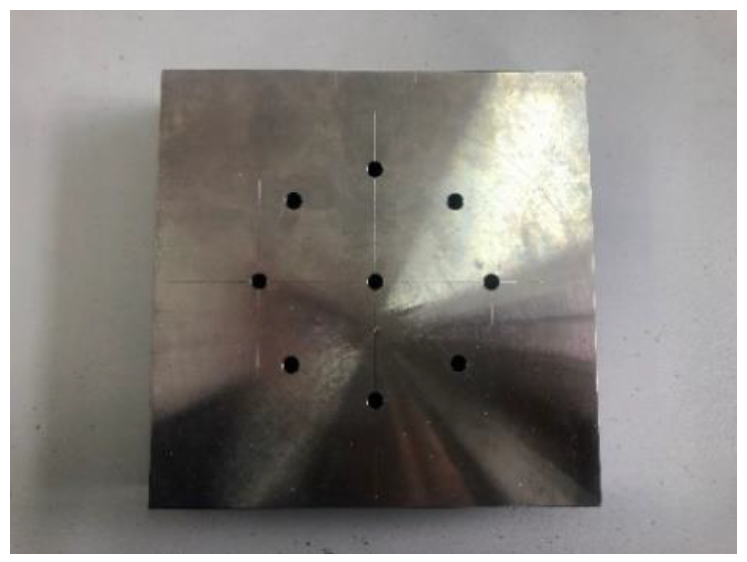
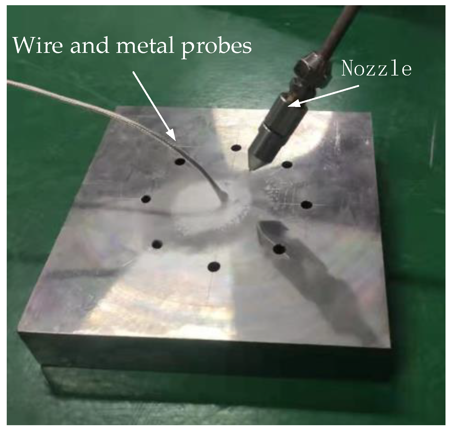
2 may dissolve the lubricating oil well. The hose delivering trace lubrication and the hose conveying the scCO2 were combined in the mixing chamber to generate droplets containing CO2 and lubricating oil. Due to the cryogenic of scCO2, the air around the nozzle condensed into ice and attached to the surface of the plate, as shown in Figure 16.
Because scCO2-MQL contains less lubricating oil during processing when examining the spray jet structure after it is ejected from the nozzle, the ejected jet structure when the pressure of scCO2 abruptly decreases is generally investigated. When high-speed airflow passed through the shock wave, the temperature increased immediately, and the concentration of solid and liquid CO2 in the airflow decreased abruptly. This led to an abrupt increase in the difference in reflectivity of the airflow at both ends of the shock wave. Therefore, the Mach disk could be captured using high-speed photography under certain conditions. When scCO2 was expelled from the nozzle, the expansion and compression waves alternated owing to an extreme disparity between the pressure inside the nozzle and the exterior pressure. The expulsion of CO2 gas led to a considerable velocity, and the initial expansion wave deviated from the horizontal direction of the nozzle by a specific angle during ejection. The pressure potential energy of scCO
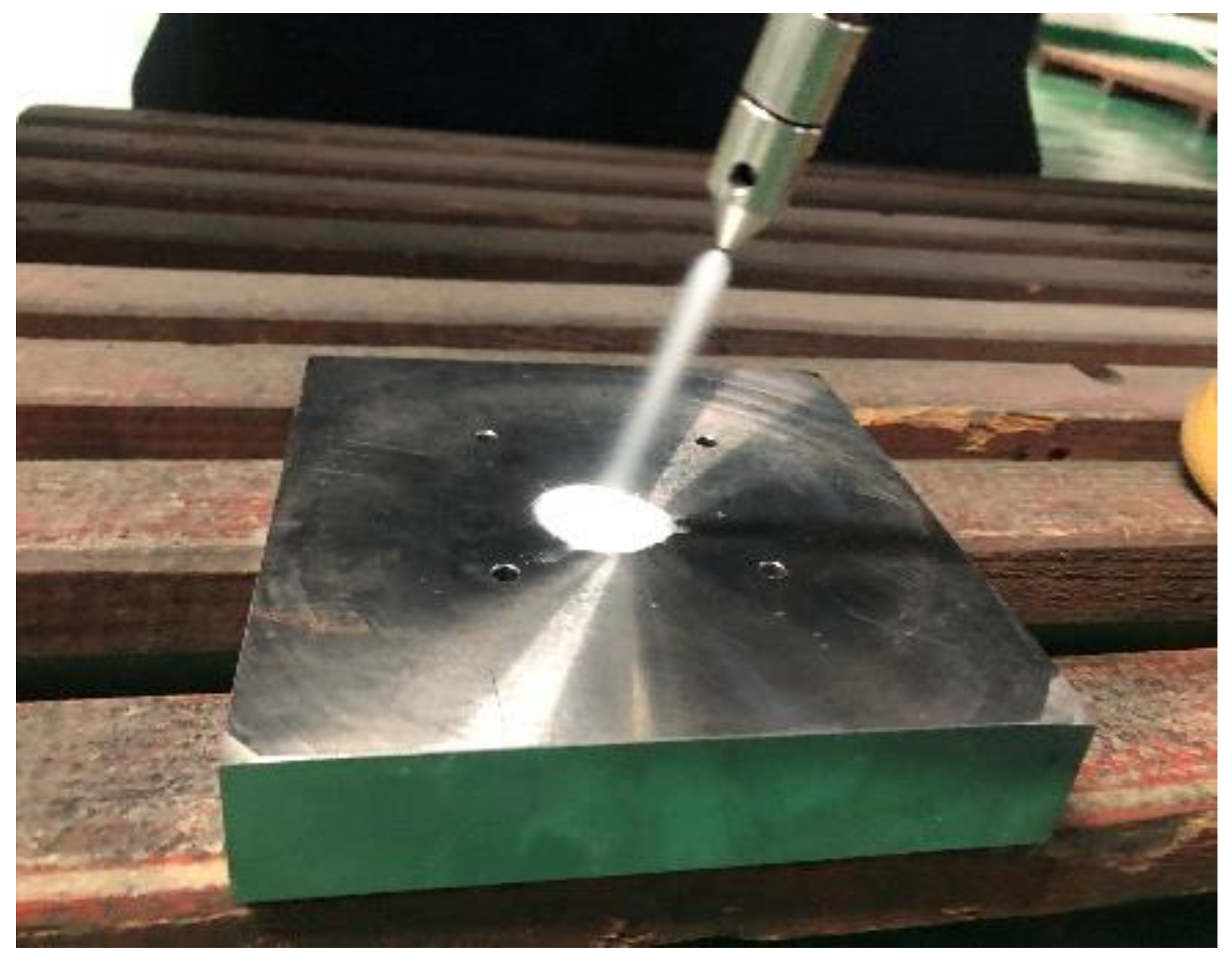
2 swiftly shifted into kinetic energy, acoustic energy, phase transition energy, and other types of energy. Evidently from Figure 17, the bottom limit of the jet was curved and assumed the form of an inverted cone. When scCO2 was discharged from the nozzle, the under-expanded CO2 expanded further. Simultaneously, an apparent white visible CO2 multiphase flow zone was detected at the bottom of the jet, and it adhered to a complicated phase transition mechanism.

4.3. Kinetic Analysis of scCO2-MQL Permeation into a Capillary

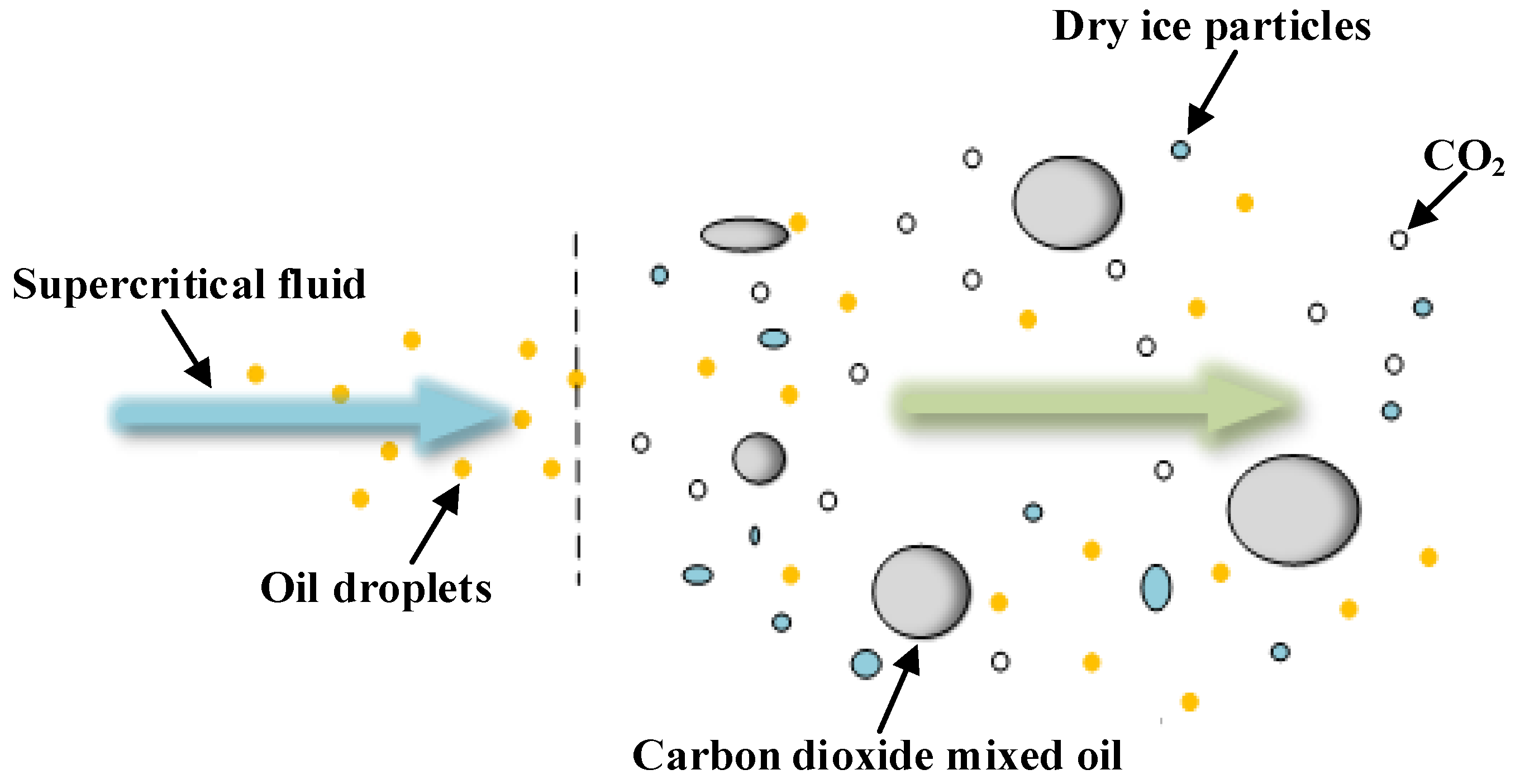
In this study, scCO2-MQL was employed as a cooling lubricant during the cutting process for titanium alloys. The obtained results indicate that three-phase gas–liquid–solid carbon dioxide was formed in the process of scCO2-MQL ejection. Moreover, owing to the strong lubrication properties of supercritical fluids to lipids, scCO2 was miscible with lubricating oil to create the scCO2-mixed oil mixture in the tube, and smaller scCO2 mixed oil droplets were formed after spraying.
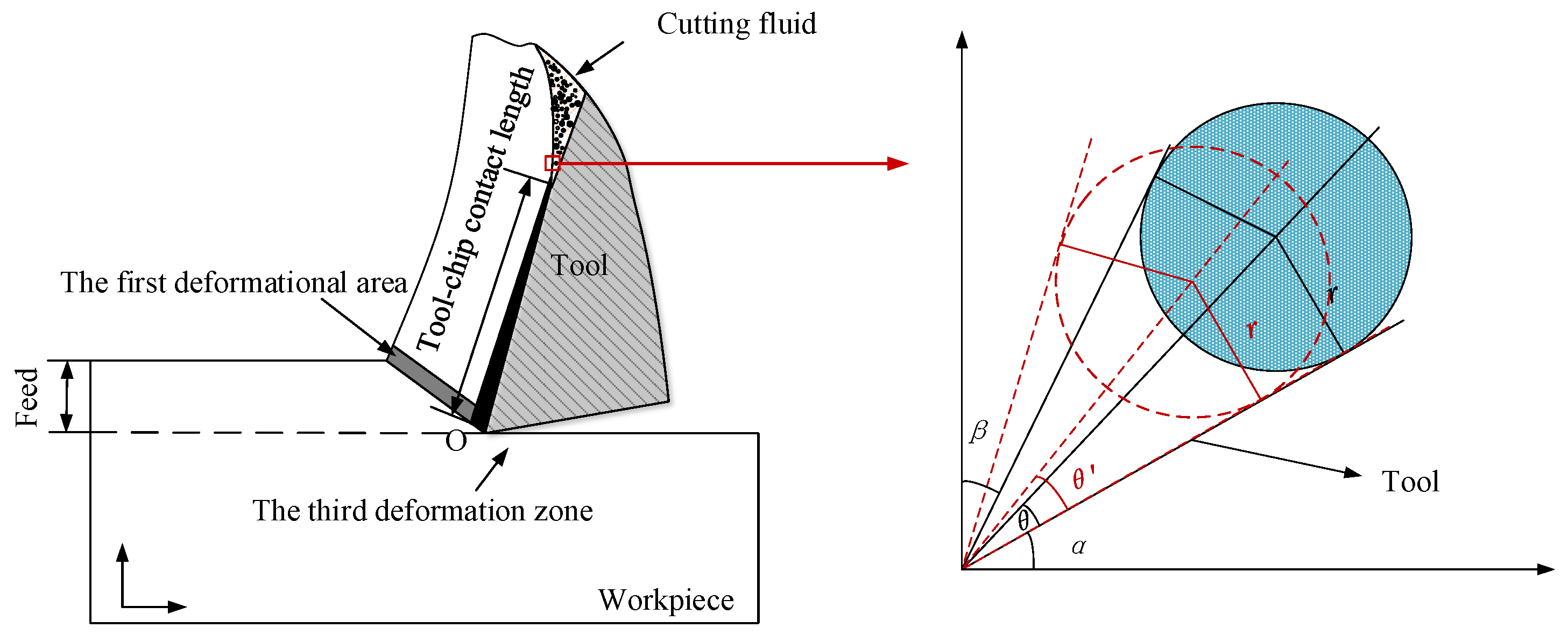
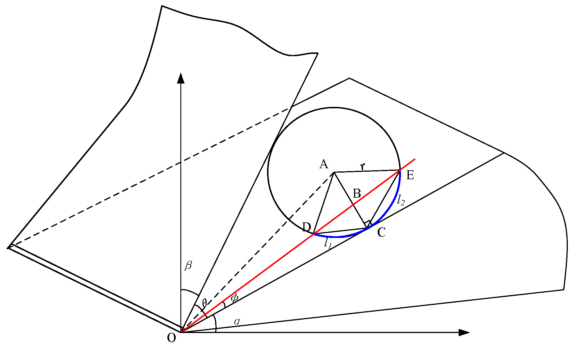
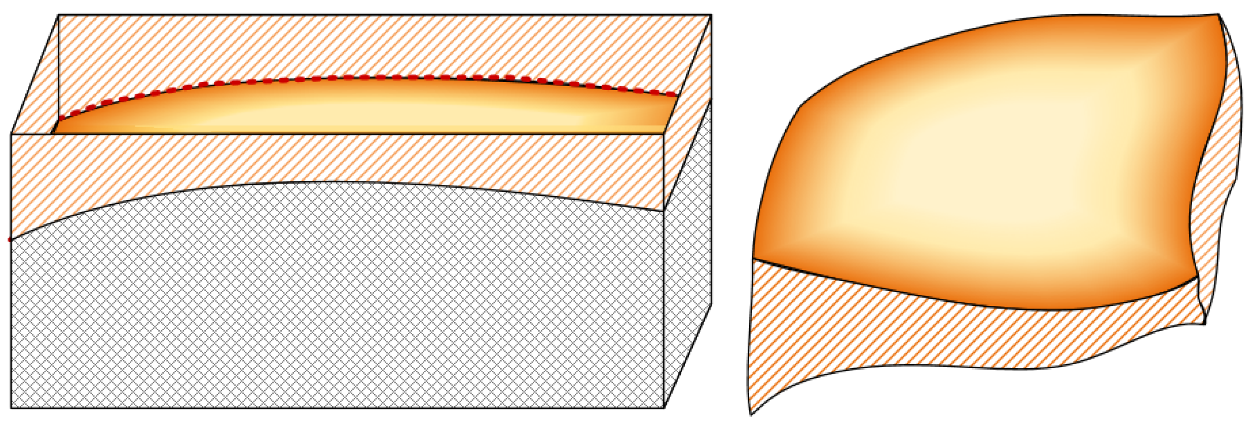
At a large carbon dioxide droplet radius, the process of entering the capillary is viewed as a time–liquid–phase infiltration state, as illustrated in Figure 18, v l indicates the rate at which the liquid phase permeates into the capillary, the yellow line represents the outline of the capillary shape, the blue dotted line represents the liquid cutting fluid, the arrow to the left indicates the direction of capillary penetration. l represents the total capillary length, 
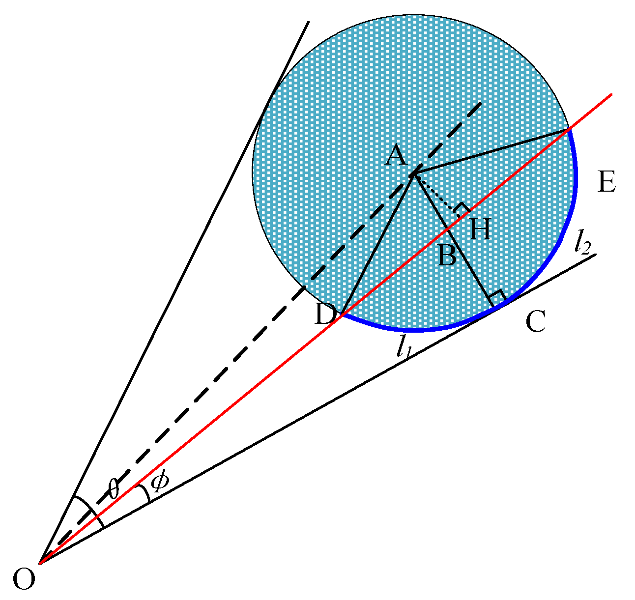
lc represents the liquid phase infiltration capillary length. The two-dimensional force analysis is presented in Figure 19. The force equilibrium relation can be expressed as:
d P z π L 2 ( x ) η v l L ( x ) a b L ( x ) d x = b a ρ π L 2 ( x ) v l t
where d P z is the pressure difference of liquid motion along the capillary tube, η is the dynamic viscosity, a is the starting point of the capillary section at any position, b is the ending point of the capillary section at any position, L ( x ) represents the expression of the capillary profile equation. v l t is the acceleration of liquid-phase motion, and v l L ( x ) is the velocity gradient of the liquid phase along the capillary radius.
According to a previous study [15], liquid carbon dioxide exists in capillary time. Essentially, capillary heat is transferred to the droplet in a gaseous time. Suppose the infiltration time is t l = f r , ρ l , c p , λ . Formula (23) was obtained using a basic physical dimensional analysis of the situation.
t l = K r α 1 ρ l α 2 c p α 3 λ α 4
where K is a dimensionless coefficient, r is the radius of the capillary at different positions, ρ l is the density of the cutting fluid, c p is the constant pressure specific heat, λ is the thermal conductivity, exponents α 1 trough α 4 are the index values of different physical quantities.
When scCO2-MQL penetrated the cutting zone, the pressure of the cutting fluid entering the capillary rose rapidly, owing to the extremely small dimensions of the capillary in the cutting zone. After the misty cutting fluid reached the capillary, it converted to steam owing to the high-temperature heat conduction of the capillary wall. Subsequently, dry ice particles were heated and evaporated in the cutting zone. The steam-state cutting fluid was poured into the capillary; simultaneously, the cutting fluid at the opening of the capillary flowed back when it was hindered, which impacted the deepening of the cutting fluid. At this point, the internal pressure and initial velocity of the cutting fluid could be determined using the ideal gas state and energy equation.
P b = ρ l R T M
where ρ l is the density of the cutting fluid, T is the internal temperature, M is the molecular weight, and R is the gas constant.
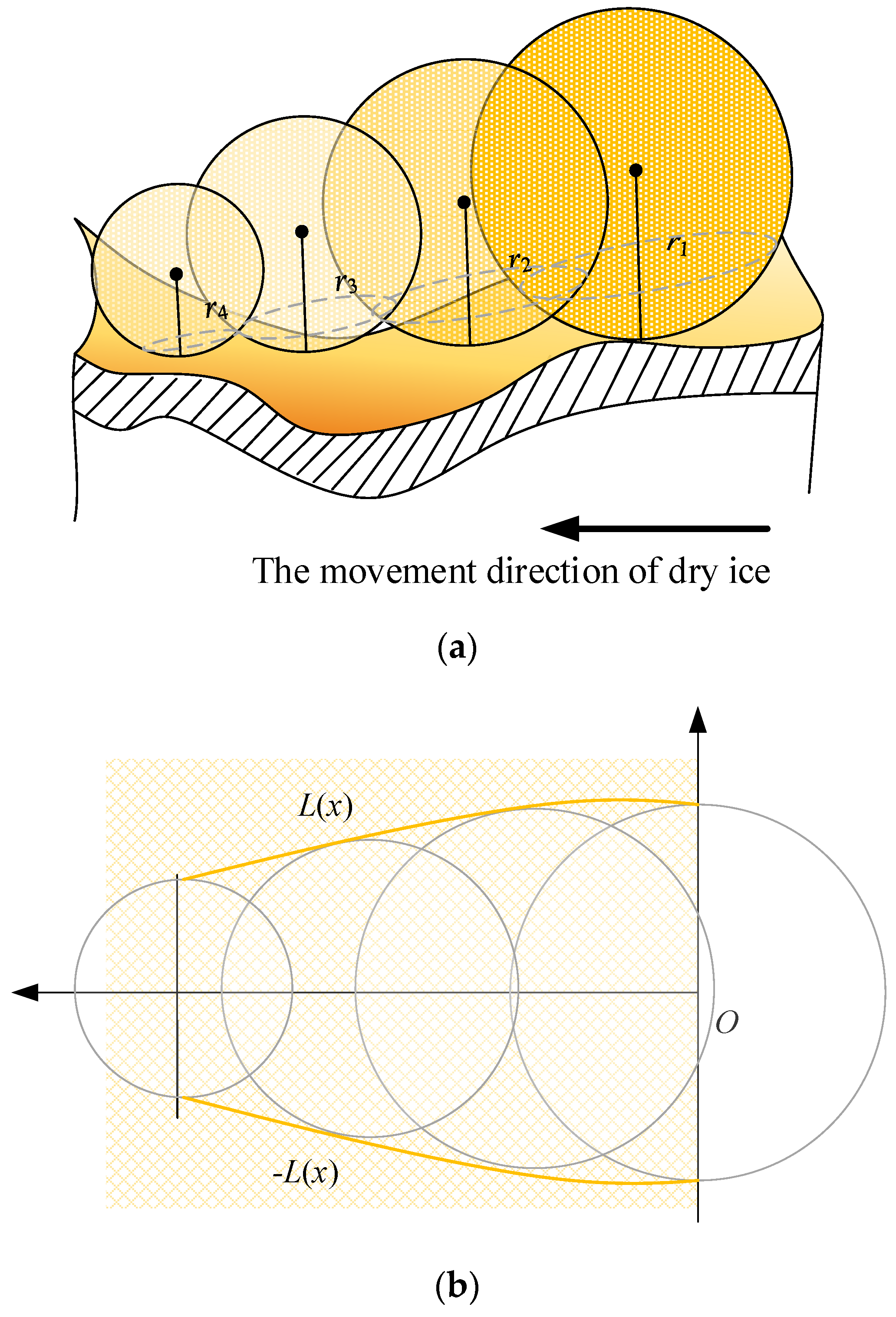
When the droplet of cutting fluid entered the capillary, its evaporation process was ephemeral, with an extremely brief duration. Therefore, it cannot be included in the total time the cutting fluid moves in the capillary. The scCO2 mixed oil droplets in scCO2-MQL were pushed forward by the compressed air. They were considered to remain in their original shape during movement and not rupture. The scCO2 mixed oil droplets flowed into the capillary tube under a pressure difference. At high temperatures, oil droplets of smaller diameters evaporated quickly. The length of the combination containing oil droplets entering the capillary was modest, and the other droplet penetrating the bottom of the capillary was a mixture of carbon dioxide and oil vapor. As the instantaneous gas density in the capillary increased, the pressure increased, and the number of molecules entering the capillary per unit of time decreased. With the continual entry of scCO2 mixed oil droplets and the evaporation of oil mist, the pressure in the capillary was equal to the external pressure, and the number of molecules entering and exiting the capillary reached equilibrium. When the droplet radius of carbon dioxide was small, it could be regarded as a droplet particle, and the motion analysis of carbon dioxide droplets was the same as that of scCO2 mixed oil droplets.
Theoretical calculation and analysis of the aerosol penetration time during scCO2-MQL auxiliary cutting were conducted. The model of aerosol penetration in the capillaries is shown in Figure 20, v l represents the direction of material flow. The yellow line represents the outline of the capillary shape, and the blue dotted line represents the liquid cutting fluid that seeps into the capillary, the dots on the left represent the aerosol particles transformed from liquid phase that has infiltrated into the capillary. L ( x ) represents the expression of the capillary profile equation. Assuming that the length of a single capillary tube is l, the moving length of the mist in the capillary tube is lg, the speed of the mist cutting fluid filling the capillary tube is vg, and the filling time is given by:
t g = l g v g
The velocity of the capillary filled with aerosol cutting fluid could be calculated using the gas dynamic equation and energy equation momentum equation for the capillary filled with the aerosol, as follows:
ρ g v g t + ρ g v g v g χ + p g χ = ρ g v g 2 f 2 L ( x )
where ρ g is the aerosol density, v g is the aerosol filling speed, v g t is the rate of change in the air mist capillary filling velocity, χ represents the coefficient of temperature conductivity, v g χ  is filling velocity gradient of aerosol, p g χ is the aerosol pressure gradient. and f is experimentally defined function.
Because of the enormous temperature differential between the high-temperature cutting zone and the scCO2 mist, the equation for adjusting the mist mixture filling the capillary is described by:
t ρ g e + v g 2 2 A d x + t ρ g v g e + v g 2 2 d x + t ρ g v g A d x = δ Q
where A is the cross-sectional area of the capillary at a certain position and e is the unit internal energy of the aerosol, χ represents the coefficient of temperature conductivity. δ represents the amount of change, Q represents the energy.
Assuming that the unit internal energy of the mist is a function of the mist pressure and mist density, Equation (27) may be rewritten as
v χ v g t ρ g A d x + v g χ e + 3 2 v g 2 + p g ρ g ρ g A d x + v g p g x A d x = δ Q
Under the premise of examining the constant density of the mist and assuming that its unit internal energy is a function of mist pressure and density, Equation (27) can be recast as Equation (28). The flow velocity of the mist mixture in the capillary tube is vg, and the mist penetration time tg can be calculated by inserting (25). The shorter the total time for scCO2-MQL entering the capillary, the more time for it to penetrate the capillary per unit time, and the better the lubrication effect.
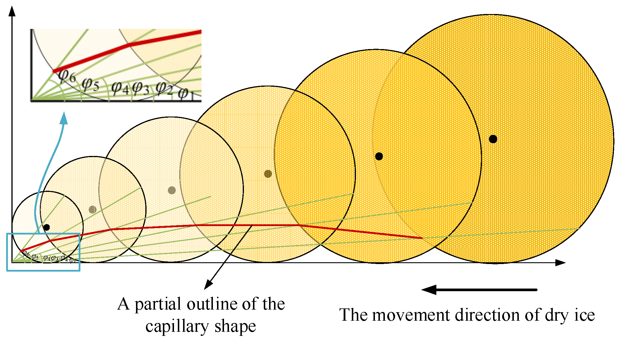
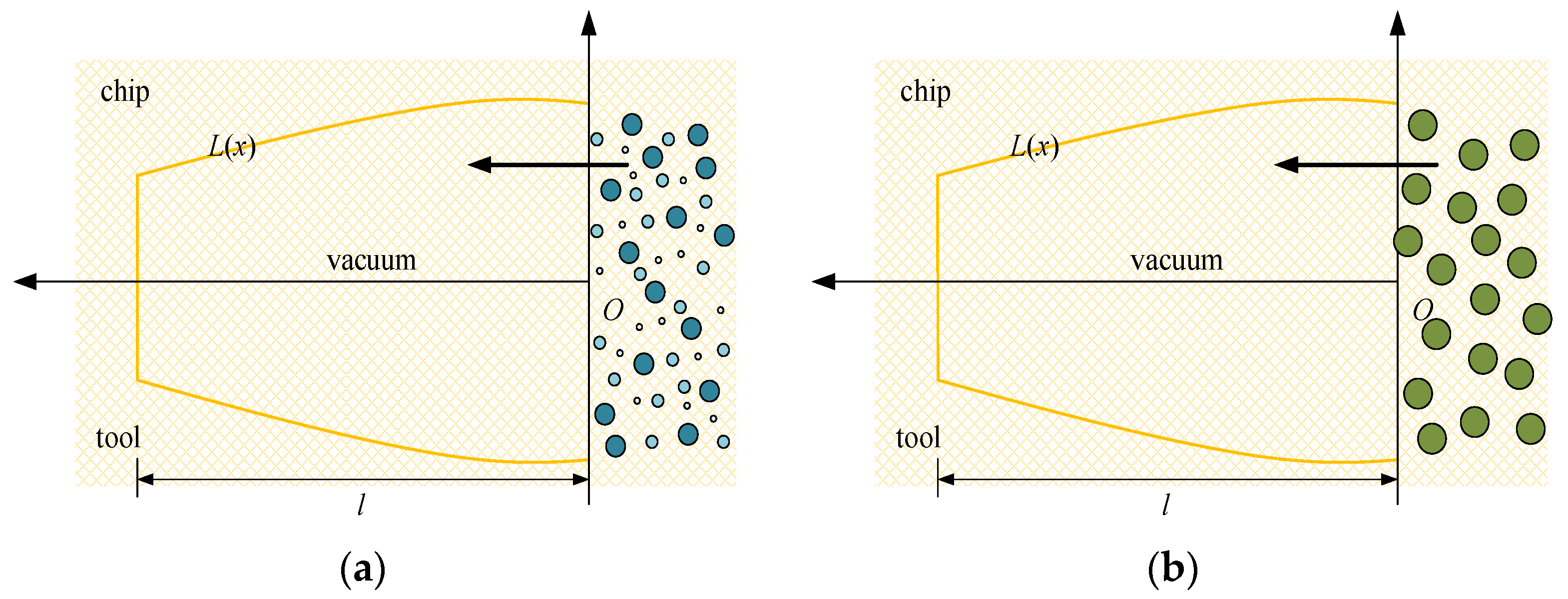
Owing to its low average molecular weight, high pressure and speed, scCO2-MQL could penetrate the cutting zone to form a boundary lubricating film. Because the supercritical fluid has a particular solubility in grease objects, the trace lubricating oil in the tube was fused with scCO2. Because the nozzle of scCO2-MQL was exceedingly small and its pressure was large, the diameters of the various droplet particles released were smaller than that of regular micro-lubrication, as shown in Figure 21. Figure 21a shows the capillary diagram of scCO2-MQL infiltration, and Figure 21b shows the capillary diagram of MQL infiltration. Evidently, the smaller the diameter of the oil mist particles, the greater the number of oil mist particles entering the capillary, the greater the number of oil mist particles filling the capillary, and the better the lubricating effect. By contrast, for higher oil mist particle diameters, the smaller the number of particles entering the capillary, the larger the gap in the capillary.
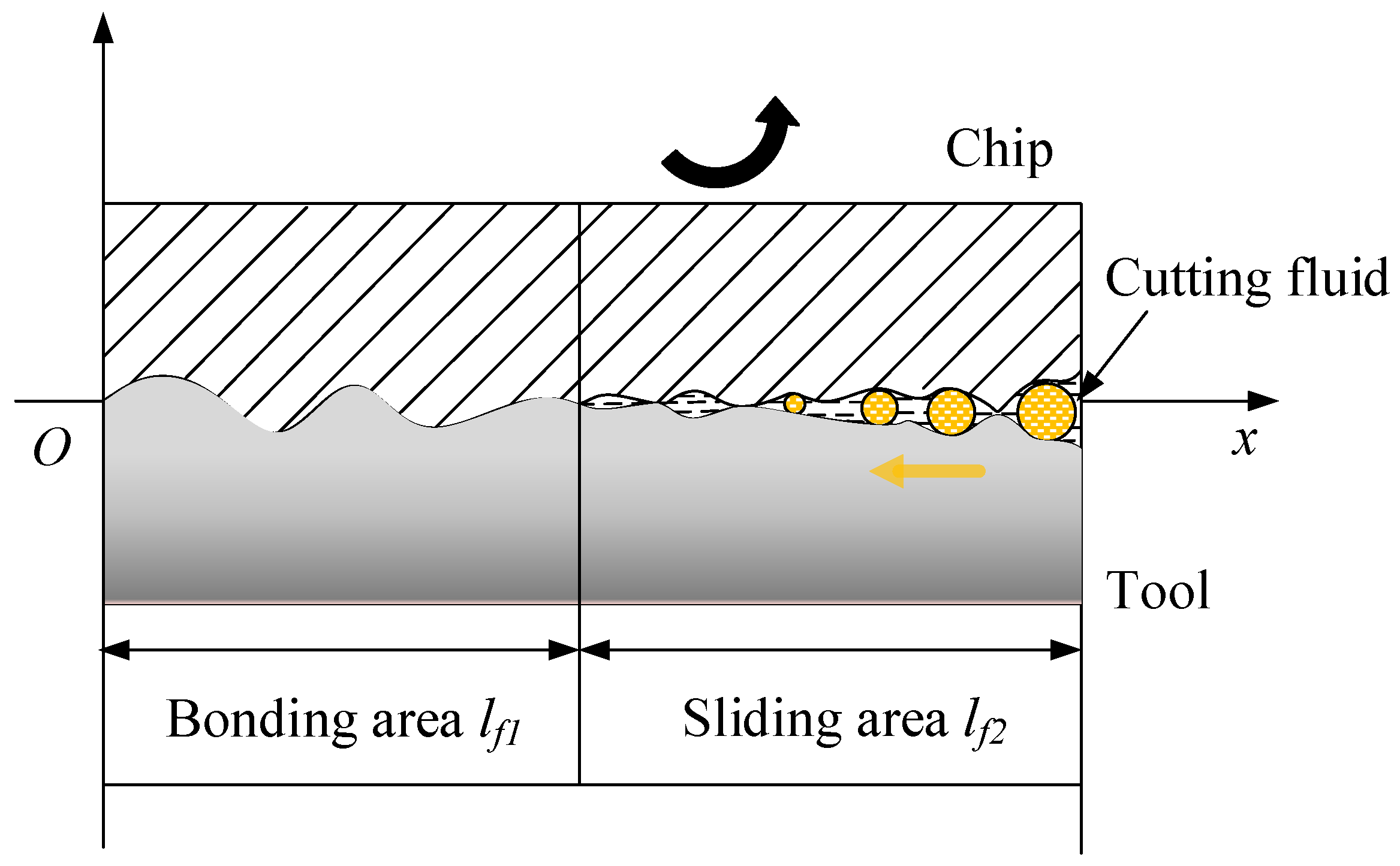
In the cutting process, the contact surface between the tool, chip, and workpiece under high-temperature and high-pressure conditions, together with the physical and chemical adsorption of the cutting fluid, are the key factors impacting lubrication [19]. Moreover, under the condition of boundary lubrication, the amount of cutting fluid employed did not result in a better lubrication effect, rather, a restricted range exists. This range relies both on surface roughness and the type of cutting fluid employed.

5. Conclusions

This study examined the use of a scCO2-MQL spray as a cutting fluid for use in titanium alloy machining. The conclusions are as follows:
1. A three-phase gas–liquid–solid mixture was produced when scCO2 was ejected from the nozzle because of the Joule–Thomson effect. Considering this phenomenon, together with the scratching and squeezing effect of dry ice particles in the cutting zone at the beginning of cutting, a capillary model based on scCO2-MQL was proposed by mathematic models. Then, the three-dimensional shape of the proposed capillary model was analyzed.
2. The temperature of the scCO2-MQL spray was between −45 °C–60 °C under various working conditions, and no significant temperature variation was observed. Among the various factors related to performance, nozzle diameter had the greatest impact on temperature. Therefore, an orthogonal experiment was conducted to measure the spray temperature of a titanium alloy plate. The results indicated that a 0.72 mm nozzle inner diameter, 40 mm injection distance, and 25 mL/h lubricating oil content provided the ideal combination for cooling.
3. The jet structure of scCO2-MQL was also investigated. Because the supercritical fluid exhibited strong solubility for oil compounds, a certain number of scCO2-oil droplets were formed when scCO2-MQL was expelled from the nozzle. The lubricating oil covered with CO2 had a smaller particle size than the lubricating oil particles directly expelled from the nozzle; therefore, it could better penetrate the capillary.
4. The dynamic process of the distinct phase of dioxide entering the capillary tube was investigated, and the time required for the cutting fluid to penetrate the capillary tube at different stages was calculated. The shorter the total time period for scCO2-MQL entering the capillary tube, the greater the penetration time per unit time and the better its lubrication effect.

Author Contributions

L.S.: Conceptualization, methodology, Formal analysis, Investigation, writing—original draft. T.W.: Writing-review & editing. E.L.: Formal analysis, Resource, Writing-review & editing, Funding acquisition. R.W.: writing—original draft. All authors have read and agreed to the published version of the manuscript.

Funding

This project was supported by the National Natural Science Foundation of China (52075135).

Data Availability Statement

Not applicable.

Acknowledgments

The authors would like to thank the National Natural Science Foundation of China (52075135). And the authors greatly appreciate the reviews, the suggestions from reviewers, and the editor’s encouragement.

Conflicts of Interest

There are no conflict of interest to declare.

References

  1. Ulutan, D.; Ozel, T. Machining induced surface integrity in titanium and nickel alloys: A review. Int. J. Mach. Tools Manuf. 2011, 51, 250–280. [Google Scholar] [CrossRef]
  2. Li, A.; Zhao, J.; Luo, H.; Pei, Z.; Wang, Z. Progressive tool failure in high-speed dry milling of Ti-6Al-4V alloy with coated carbide tools. Int. J. Adv. Manuf. Technol. 2012, 5, 465–478. [Google Scholar] [CrossRef]
  3. Yildiz, Y.; Nalbant, M. A review of cryogenic cooling in machining processes. Int. J. Mach. Tools Manuf. 2008, 48, 947–964. [Google Scholar] [CrossRef]
  4. Jawahir, I.; Attia, H.; Biermann, D.; Duflou, J.; Klocke, F.; Meyer, D.; Newman, S.; Pusavec, F.; Putz, M.; Rech, J.; et al. Cryogenic manufacturing processes. CIRP Ann. 2016, 65, 713–736. [Google Scholar] [CrossRef]
  5. Weinert, K.; Inasaki, I.; Sutherland, J.; Wakabayashi, T. Dry Machining and Minimum Quantity Lubrication. CIRP Ann. 2004, 53, 511–537. [Google Scholar] [CrossRef]
  6. Stephenson, D.A.; Skerlos, S.J.; King, A.S.; Supekar, S.D. Rough turning Inconel 750 with supercritical CO2-based minimum quantity lubrication. J. Mater. Proc. Technol. 2014, 214, 673–680. [Google Scholar] [CrossRef]
  7. Mazzoldi, A.; Hill, T.; Colls, J.J. Assessing the risk for CO2 transportation within CCS projects. CFD modelling. Int. J. Greenh. Gas. Control. 2011, 5, 816–825. [Google Scholar] [CrossRef]
  8. An, Q.; Cai, C.; Zou, F.; Liang, X.; Chen, M. Tool wear and machined surface characteristics in side milling Ti6Al4V under dry and supercritical CO2 with MQL conditions. Tribol. Int. 2020, 151, 106511–106534. [Google Scholar] [CrossRef]
  9. Bagherzadeh, A.; Budak, E. Investigation of machinability in turning of difficult-to-cut materials using a new cryogenic cooling approach. Tribol. Int. 2018, 119, 510–520. [Google Scholar] [CrossRef]
  10. Yuan, Y.; Wang, C.; Yang, J.; Zheng, L.; Weiqiang, X. Performance of supercritical carbon dioxide (scCO2) mixed with oil-on-water (OoW) cooling in high-speed milling of 316L stainless steel. Procedia CIRP 2018, 77, 391–396. [Google Scholar] [CrossRef]
  11. Rahim, E.; Rahim, A.; Ibrahim, M.; Mohid, Z. Experimental investigation of supercritical carbon dioxide (SCCO2) performance as a sustainable cooling technique. Procedia CIRP 2016, 40, 637–641. [Google Scholar] [CrossRef] [Green Version]
  12. Litwa, P.; Wika, K.K.; Zonuzi, A.; Hitchens, C. The influence of cutting conditions on surface integrity in high feed milling of Ti-6Al-4V with supercritical CO2 cooling. MM Sci. J. Spec. Issue HSM 2019, 3071–3077. [Google Scholar] [CrossRef] [Green Version]
  13. Cai, C.; Liang, X.; An, Q.; Tao, Z.; Ming, W.; Chen, M. Cooling/lubrication performance of dry and supercritical CO2-based minimum quantity lubrication in peripheral milling Ti-6Al-4V. Int. J. Precis 2021, 8, 405–421. [Google Scholar] [CrossRef]
  14. Williams, J.A.; Tabor, D. The role of lubricants in machining. Wear 1977, 43, 275–292. [Google Scholar] [CrossRef]
  15. Godleviski, V.A.; Volkov, A.V. The Kinetics of Lubricant Penetration Action during machining. Lubrication Science 1997, 9, 127–140. [Google Scholar] [CrossRef]
  16. Liu, J.; Han, R.; Sun, Y. Research on experiments and Action mechanism with water vapor as coolant and lubricant in Green Cutting. Int. J. Mach. Tools Manuf. 2005, 45, 687–694. [Google Scholar] [CrossRef]
  17. Wang, S.; Clarens, A.F. Analytical model of metalworking fluid penetration into the flank contact zone in orthogonal cutting. J. Manuf. Proc. 2013, 15, 41–50. [Google Scholar] [CrossRef]
  18. Han, R.; Zhang, Y.; Wang, Y. The Effect of Superheated Water Vapor as Coolant and Lubricant on Chip Formation of Difficult-to-cut Materials in Green Cutting. Key Eng. Mater. 2008, 375–376, 172–176. [Google Scholar] [CrossRef]
  19. Hardy, W.B.; Hardy, J.K., II. Note on static friction and on the lubricating properties of certain chemical substances. Lond. Edinb. Dublin Philos. Mag. J. Sci. 1919, 38, 32–48. [Google Scholar] [CrossRef]
Figure 1. Capillary model for the tool–chip contact area in a machining process in which a cutting fluid is employed.
Machines 11 00291 g001
Figure 2. Phase diagram for scCO2, showing the gas, liquid, and solid states at various temperatures and pressures.
Machines 11 00291 g002
Figure 3. Substances ejected from scCO2-MQL.
Machines 11 00291 g003
Figure 4. Analysis of dry ice particles.
Machines 11 00291 g004
Figure 5. Capillary formation analysis model for tool contact with dry ice particles.
Machines 11 00291 g005
Figure 6. Analysis of a single dry ice particle.
Machines 11 00291 g006
Figure 7. Contact analysis of dry ice in the tool-chip contact area. (a) The capillary radius decreases gradually, (b) The top view of the capillary tube.
Machines 11 00291 g007
Figure 8. Boundary shape of the capillary cross-section.
Machines 11 00291 g008
Figure 9. Three-dimensional view of the capillary tube model used in this study.
Machines 11 00291 g009
Figure 10. The scCO2-MQL cutting fluid generation device.
Machines 11 00291 g010
Figure 11. Thermal resistance temperature measuring device used in this study. (a) Paperless recorder, (b) Wire and metal probes.
Machines 11 00291 g011
Figure 12. γ-TiAl sheet used in temperature measurements.
Machines 11 00291 g012
Figure 13. γ-TiAl sheet real temperature measuring plate.
Machines 11 00291 g013
Figure 14. Injection experiment of scCO2-MQL.
Machines 11 00291 g014
Figure 15. Comparison of temperature values for the influencing factors of nozzle diameter.
Machines 11 00291 g015
Figure 16. Injection of scCO2 oil into a sample.
Machines 11 00291 g016
Figure 17. scCO2 jet observed in this study.
Machines 11 00291 g017
Figure 18. Liquid particle infiltration capillary model.
Machines 11 00291 g018
Figure 19. Two-dimensional force stress analysis of an arbitrary capillary tube.
Machines 11 00291 g019
Figure 20. Model of air mist penetrating the capillary tube.
Machines 11 00291 g020
Figure 21. Two different cutting fluid permeation capillaries. (a) The capillary diagram of scCO2-MQL infiltration, (b) The capillary diagram of MQL infiltration.
Machines 11 00291 g021
Table 1. Results obtained using an orthogonal experiment.
FactorNozzle Diameter (mm)Jet Distance (mm)Lubrication Flow (mL/h)
Level
10.312025
20.624050
30.726075
Table 2. Temperature results obtained using the orthogonal experiment.
NumberNozzle Diameter (mm)Jet Distance (mm)Lubrication Flow (mL/h)Temperature (°C)
10.322025−48.4
20.324050−47.9
30.326075−43.8
40.512050−51.7
50.514075−54.6
60.516025−52.1
70.722075−57.4
80.724025−59.9
90.726050−55.2
Table 3. Mean and R values for different factors at different levels in the test range.
MeanNozzle Diameter (mm)Jet Distance (mm)Lubrication Flow (mL/h)
1−46.70−52.50−53.47
2−52.80−54.13−51.6
3−57.50−50.37−51.93
R10.83.771.87
Disclaimer/Publisher’s Note: The statements, opinions and data contained in all publications are solely those of the individual author(s) and contributor(s) and not of MDPI and/or the editor(s). MDPI and/or the editor(s) disclaim responsibility for any injury to people or property resulting from any ideas, methods, instructions or products referred to in the content.

