Review

Recent Development for Ultra-Precision Macro–Micro Dual-Drive System: A Review

College of Mechanical Engineering, Xi’an University of Science and Technology, No. 58 Yanta Middle Road, Xi’an 710054, China
*
Author to whom correspondence should be addressed.
Machines 2023, 11(1), 96; https://doi.org/10.3390/machines11010096
Submission received: 12 December 2022 / Revised: 6 January 2023 / Accepted: 9 January 2023 / Published: 11 January 2023
(This article belongs to the Special Issue Recent Progress of Thin Wall Machining)

Abstract

:
Macro–micro dual-drive technology uses a micro-drive system to compensate for motion errors of a macro-drive system, solving the contradiction between large travel and high-precision motion. Additionally, it has a wide range of applications in the ultra-precision field. Therefore, it is necessary to analyze and research the ultra-precision macro–micro dual-drive system. Firstly, this paper analyzes the history of ultra-precision technology development and summarizes the research status of ultra-precision technology processing and application. Secondly, the micro-drive mechanism design and macro–micro-drive mode of macro–micro dual-drive technology, which can solve the contradiction of large stroke and high precision, are reviewed, and the application of macro–micro dual-drive technology in an ultra-precision system is summarized. Finally, the challenges and development trends of the ultra-precision macro–micro dual-drive system are analyzed. The research in this paper will play an important role in promoting the development of the ultra-precision system and macro–micro dual-drive technology.

1. Introduction

With the higher accuracy requirements of mechanical systems, the motion accuracy requirements of mechanical systems applied in the equipment manufacturing industry are also getting higher [1,2,3]. Precision and ultra-precision machining technology is an important way to realize the machining of precision machinery equipment, which has been widely used in various fields such as aerospace, national defense, optics, machinery, and electronics. Many scholars have studied ultra-precision technology and made some achievements in high precision and so on.
Precitech’s Nanoform 350 has a hydrostatic bearing and linear motor drive on both slides for position measurement with a linear scale resolution of 8.9 nm [4]. Nanotech 500FG has three linear axes and is a typical multi-axis diamond grinder, as shown in Figure 1a. It can generate any conformal optical surface (including aspherical surface and non-axisymmetric surface) shape within the processing range of 250 mm × 250 mm × 300 mm. It has independently mounted X and Z axes with a “T” configuration, and the Y-axis mount is integrated with the Z-axis to eliminate "stacking" axes. The stiffness of the slide is 350 N/ μ m , and the motion accuracy of the working spindle is not more than 50 nm. PicoAce has a static loop stiffness of 100 N/min in the vertical direction and achieves a high motion resolution of 1 nm on the Z-axis, as shown in Figure 1b. It can produce an optically quality surface finish on a range of hard and brittle materials with low levels of sub-surface damage. The Fanuc Robonano α-0iA is another famous five-axis milling machine, as shown in Figure 1c. The Y slider is used for vertical movement with a stroke of 20 mm, and the Z slider can move in a direction perpendicular to the X-Y plane [5]. Shigeaki Goto et al. proposed an ultra-precision STM Z scanner. It was used to measure the surface profile of the microstructure with an amplitude of tens of microns. The linear encoder produced a minimum effective bit resolution of 0.5 nm across the full stroke of the actuator, and the peak-valley value of Z-scan nonlinearity was less than 10 nm in the effective measurement range of 50 μ m [6]. Wang et al. proposed that the research aims to develop an innovative method to prevent overloading the aerostatic bearings and detect the engagement of each copper layer in a multi-layer PCB drilling hole, as shown in Figure 1d. Most importantly, monitored tool wear for high-speed drilling is based on the unique characteristics of aerostatic bearings. This innovation was reflected in the development of an instrumented smart air hydrostatic bearing spindle for high-speed PCB drilling, and the instrumented smart spindle could perform spindle self-protection, as shown in the axial displacement measurement. By achieving higher feed rate parameters, the axial displacement generated during drilling could be as high as 3.6 m/min at a given high feed rate parameter, even less than half of the designed air-bearing film clearance [7].
Precision feed technology is an important method to realize ultra-precision machining technology. The servo motor and ball screw pair, linear motor, and other macro-driving modes can meet the general requirements of precision machining technology while realizing the large-stroke movement, but at present, some ultra-precision fields, such as ultra-precision CNC machining, electronic packaging movement platform, and biological medical equipment, have very high requirements (submicron or even nanometer accuracy) for the positioning accuracy of mechanical systems. In this case, these macro-drive methods cannot meet the above accuracy requirements independently. The precision of the micro-positioning system based on the combination of the piezoelectric ceramic actuator, magnetostrictive actuator, and flexure hinge can reach sub-micron or even nanometer level. However, its motion stroke is generally limited to between 10 μ m and 100 μ m , which cannot meet the requirements of large stroke (generally m class and above). Therefore, either macro-drive or micro-drive with a single drive cannot meet the requirements of large-stroke and high-precision motion at the same time, which becomes a bottleneck problem restricting the development of ultra-precision machining technology [8,9,10,11,12,13].
Macro–micro dual-drive technology uses the macro-drive system to provide large-stroke motion, uses the micro-drive system to compensate for the error to provide high-precision motion, and then realizes the system of large-stroke and high-precision motion, which can solve the contradiction between the above motion and high precision, thus becoming an important technology of high-precision motion and machining. In the ultra-precision system, macro–micro dual-drive technology can greatly improve the motion accuracy of the system, realize large-stroke high-precision movement, and greatly promote the development of ultra-precision technology.
This paper analyzes and reviews the ultra-precision macro–micro dual-drive system and puts forward the challenges and development trends in this study, which can promote the development of ultra-precision and macro–micro dual-drive technology. The paper is organized as follows: Section 2 introduces the development history of ultra-precision technology, and the research status of machining and application of ultra-precision technology is summarized. Section 3 introduces the micro-drive mechanism design and macro–micro-drive mode of macro–micro dual-drive technology and summarizes the application of macro–micro-drive technology in an ultra-precision system. Section 4 is the conclusion.

2. Ultra-Precision Technology

Ultra-precision machining technology is measured by the highest machining accuracy in each historical period. As long as this standard is exceeded, these machining methods can be called ultra-precision machining technology. The technology of precision and ultra-precision has absorbed more and more of the latest scientific and technological achievements. Control technology, processing technology, materials science, electronic technology, mechanical manufacturing technology, and many other academic subjects have been widely used in and serve for precision and ultra-precision technology, and it has become not only a simple process technology but also a complex system engineering integrating numerous modern latest scientific and technological achievements [14,15,16,17,18].
The precision of machining increased from 1 mm in the early 19th century to 0.01 mm in the 20th century and further increased to ultra-precise 0.01 μ m in the middle of the 20th century. In current processing technology, it has reached the nanometer level. The first ultra-precision diamond tool technology was developed in the United States in the late 1950s. In the 1970s, ultra-precision machining technology was successfully applied to the manufacture of computer memory disks used in hard disk drives, as well as to photosensitive elements used in many photocopier and printer applications; these applications require extremely high geometric precision and ultra-smooth surfaces. Thus, the single-point diamond is with high efficiency in ultra-precision surface machining. Compared to multiple processes such as machining, grinding, and polishing, in that era, the use of ultra-precision machining continued to be the core technology of single-point diamond turning [19]. Subsequently, the technology was popularized in various industries, and the grinding process was developed to meet commercial and national defense needs. With some major advances in the design and construction of control, feedback systems, servo drivers, and general machines, today’s ultra-precision machining systems have become more productive and accurate. Machining errors can be accurately measured and further applied in analysis and combination based on closed-loop machining ideas [20,21,22,23,24,25,26]. Nowadays, ultra-precision technology has been widely used in processing, biological, military, and other industries. The research on this technology mainly focuses on ultra-precision machining and ultra-precision technology application.
At present, the field of ultra-precision machining is divided into four fields: ultra-precision cutting, ultra-precision grinding, ultra-precision polishing, and ultra-precision non-traditional machining. These ultra-precision machining processes should be well-known to match the best methods. Surface roughness is the limit of machining precision in ultra-precision machining, and surface roughness is obtained on the basis of machining precision. Ultra-precision cutting machining precision of less than 0.01 μ m and surface roughness of less than 0.01 μ m are used for processing non-ferrous materials [27]. Ultra-precision grinding is used for machining various precision parts and components with a machining accuracy of less than 0.1 μ m and surface roughness of less than 0.025 μ m [28]. Ultra-precision polishing machining precision of less than 0.01 μ m and surface roughness of less than 0.025 um are used to flatten different materials [29]. Ultra-precision non-traditional machining precision of less than 0.01 um and surface roughness of less than 0.025 um are used for all kinds of hard-to-cut materials [30]. To sum up, the surface roughness of the parts processed by ultra-precision cutting is lower. Table 1 summarizes the machining accuracy of each processing technology.
Having high-quality ultra-precision machine tools is the most basic and important condition for achieving ultra-precision machining. In addition to sharp cutting tools or fine grinding tools, high dynamic stiffness and precision machines and micro-feeding systems are essential for the removal of ultrafine materials in cutting, grinding, polishing and non-traditional processing. It is affected by heat during processing, and the processing system will gradually heat up. After the deformation of mechanical parts, it will affect mechanical equipment and tools, thus gradually reducing the processing accuracy of mechanical parts. Burak Sence et al. proposed a new real-time trajectory generation algorithm for precise and high-speed turning applications, the tool’s turn trajectory was generated by the discontinuous axis velocity command at the segment connection of FIR (finite impact response) filtering, and the profile error at acute angles was analyzed and controlled by optimizing the acceleration profiles of the previous and current segments. Residual vibration due to structural mode excitation was avoided by adjusting the filter delay of all drivers, as shown in Figure 2a. Experiments had proven that the cycle time and accuracy of drawing the profile of the Cartesian tool path had been significantly improved [31]. In order to achieve the necessary tool setting accuracy of only a few nanometers, a new actuating mechanism based on thermal expansion was proposed by Lars Schonemann and Oltmann Riemerin, as shown in Figure 2b. The performance of the actuating mechanism was assessed in static tests and for the first time on the spindle set with a rotating handle. The experimental results showed that under the condition of 240 min−1, the thermal expansion rate could reach 1 μm, which confirmed the feasibility of the method [32]. Rakuffand Cuttino designed a 2 mm stroke voice coil FTS system, as shown in Figure 2c. When the system was applied to dispose of a petal-shaped aspheric surface (Ø30 mm), the surface roughness ranged from 20 nm to 30 nm [33]. J.C. Aurich et al. introduced a new micro-shaft grinding tool with a cylindrical tip diameter between 13 mm and 100 mm, and the manufacture of the tool itself was carried out on a prototype desktop; in the first experimental tests of the tool, very low surface roughness values and sharp edges without burrs were obtained, as shown in Figure 2d [34]. Y. Namba et al. used various methods to process materials, as shown in Figure 2e. The surface roughness of 0.23 nm rms was obtained on the aspheric molding mold with a diameter of 300 mm, and a surface roughness of 0.16 nm rms was achieved on the platin μ m /carbon multilayer mirror, which was copied from the plane mold [35]. Yasuhiro Kakinuma et al. studied the characteristics of low-temperature micromachining and its application in the fabrication of microfluidic chips. From the perspective of cutting energy and machining surface quality, low cutting speed and about 250 nm feed per tooth were the first choices to obtain fine surfaces. As shown in Figure 2f, low-temperature micro-milling was an effective process for manufacturing 3D microfluidic chips with sub-micron to millimeter channels [36].
Ultra-precision manufacturing is a dynamic research field with a huge range of applications, and the technology will be used more and more widely. The broader applications of ultra-precision manufacturing (UPM) include the processing of semiconductors and optical components with high dimensional accuracy. Ultra-precision and micro-manufacturing play an important role in advanced manufacturing technology, and in recent decades, the application of ultra-precision cutting and micro-machining has been increasing and promoting the market economy. Ultra-precision processes allow for surface roughness down to the nanoscale and are used, for example, in the manufacture of optical components. Micro-machining is an important technology for manufacturing micro-components, micro-features and micro-structures [37,38,39,40].
In micro-machining, Eastman Kodak Company had developed a five-axis computer-controlled ion imaging system (IFS) for final imaging of large-scale optical components, processing components with primary sizes up to 2.5 × 2.5 × 0.6 m, providing stable ion beam removal with a standard Kaufman type wide-beam ion source for physical sputtering of the desired material from the target optical surface [41]. Li et al. proposed a self-stereoscopic (DPA) three-dimensional measurement system based on parallax mode. The system used a micro-lens array to capture the original 3D information of the tested surface in a single snapshot through a CCD camera, as shown in Figure 3a. The proposed DPA 3D measurement system could repeatedly measure 3D micro-structure surfaces with sub-micron level measurement and achieve high-precision in situ measurement of micro-structure surfaces [42]. Zhang et al. used a 5-axis ultra-precision machine tool system (mole nanotechnology 350FG) to achieve the above DME of intaglio printing, as shown in Figure 3b. The gravure pattern consists of tens of thousands of cells on a metal roller die, and the resolution of the three linear axes of the ultra-precision machining system was 1 nm, and the resolution of the B and C rotation axes was 0.00001° [43]. Lei Li and Allen Y. Yi designed and manufactured a unique free-form micro-lens array for compact compound eye cameras, as shown in Figure 3c, to achieve a large field of view. The field of view of the micro-lens array was 48° × 48°, and the thickness was only 1.6 mm [44].
With the rapid development of industrial technology, ultra-precision technology has been used in aerospace technology. The optical requirements of the European Very Large Telescope (E-ELT) and the optical requirements for future extreme ultraviolet (EUV) lithography steppers, increasingly shorter optical wavelengths work to achieve feature size creation capabilities of 13 nm (or even 6 nm) [45]. Yang et al. designed the Winston baffle, which was developed for the space observation camera of MIRIS (multi-purpose infrared imaging system). Winston conical flaps were plated after electroless nickel plating and applied to MIRIS flight models [46].

3. Ultra-Precision Macro–Micro Dual-Drive System

With the development of science and technology, ultra-precision technology has put forward higher requirements, especially motion accuracy, response speed, force feeling, controllability, flexibility, and other aspects of the requirements are increasingly high. For micromanipulation tasks, while paying attention to high-precision and nanoscale positioning detection, it is also necessary to take into account the large-scale macro-positioning at the micron level. For example, in the process of biological cell operation, cell transfer and transport should be completed, and cell injection, cutting, and fusion should also be realized [47,48]. The contradiction between macro and micro is very prominent if the traditional single drive mode is used, where large strokes can be achieved or high precision can be achieved, but both cannot be taken into account for the above situation. In the mid and late 1980s, scholars put forward the preliminary idea of a macro–micro dual-drive system [49,50].
The macro–micro-drive technology was first proposed by Professor Andre Sharon of MIT in 1984, and the proposal of this technology solved the problem that macro-drive and micro-drive alone could not solve the contradiction between large stroke and high precision. The macro–micro dual-drive system is composed of a micro-actuator and a macro-actuator. The macro-drive system provides large-stroke motion, and the micro-drive system compensates for the error caused by the macro-actuator, so the system has a higher precision. Solving the problem that the traditional mechanical system cannot realize high precision and simultaneously take the large-stroke movement into account, the macro–micro dual-drive technology has been widely concerned [51,52,53].
Many research institutions and scholars have conducted in-depth research on macro–micro dual-drive technology [54,55,56,57,58]. The working principal diagram of the macro–micro-drive system is shown in Figure 4: A macro-motor and its driver realize macro-drive system internal closed-loop control, and a micro-driver and its driver realize micro-drive system internal closed-loop control. Sensors detect and feedback the output of macro–micro system motion. The controller allocates the amount of motion to the macro- and micro-drive systems to realize the coupling control of the macro- and micro-drive systems.

3.1. Research on Macro–Micro Dual-Drive Technology

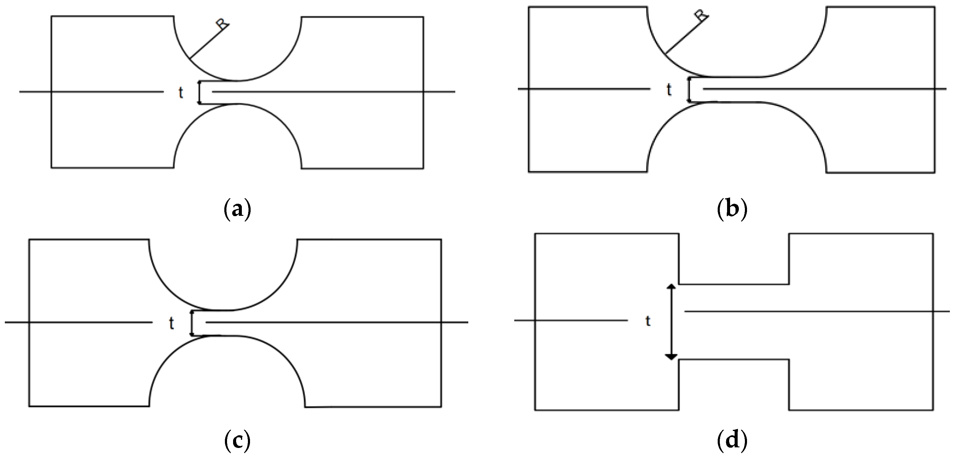
3.1.1. Design of Micro-Drive Mechanism

In the macro–micro-drive system, the micro-moving mechanism can achieve high precision, and the micro-moving mechanism mainly adopts a flexible hinge structure in the current research. With the wave of micro and nanotechnology leading to revolutionary changes in many fields such as manufacturing, information, materials, biology, medicine, and national defense, the flexible mechanism has been widely used in the field of sub-micron level or even nanolevel for the positioning accuracy requirements of micro-electronics, micro-manufacturing and micro-operation of optoelectronic components, micro-electro-mechanical systems (MEMS), biomedical engineering, etc. Scholars have carried out in-depth research on it.
In 1965, Paros and Weisbord applied the mechanical deformation formula of materials to derive the rotational stiffness of arc-notched flexible hinges, which has been used to this day [59]. Smith et al. adopted an oval design for the shape of the gap and analyzed and derived the formula for the rotational stiffness of each axis [60]. Professor Nicolae Lobontiu used chamfered notch, parabolic shape, and hyperbolic shape to analyze the performance of various notch flexure hinges and found that the parabolic notch can have greater rotational flexibility [61,62]. Generalized deep V type [63], asymmetric [64], and mixed notch [65] demonstrate better working performance. According to the shape of the weak part of the flexible hinge, the commonly used flexible hinge types are straight round, arc, parabolic, and straight beam, as shown in Figure 5.
For most metals, the elastic modulus of the material will not change much by changing the element type and processing. However, when heat and cold treatment were carried out, the tensile strength and yield strength of the material increased, and the material became more brittle. In the current research, 60Si2Mn, 65Mn, and QBe2 are the most used materials. Its parameters are shown in Table 2.
The micro-drive mechanism designed based on the principle of flexible hinge composite motion can be used independently to obtain precise output. It can also be combined with a macro-drive system to form a macro–micro dual-drive system to achieve large-stroke and high-precision macro–micro motion. When the micro-drive mechanism is used alone, it can realize the functions of linear transmission, displacement amplification, displacement reduction (accuracy improvement), displacement conversion (high precision of straight line into high precision of rotation), etc., and is often used in precision motion processing and other fields.
Mohd Nashrul Mohd Zubir et al. designed a flexible micro-clamping mechanism with the function of outputting the accurate amplification displacement, as shown in Figure 6a. Driven by a piezoelectric ceramic actuator, this mechanism could precisely output the displacement, and its magnification was close to 3.68, which is with the advantage of high precision [66]. Tung-Li Wu et al. designed a nanoscale positioning device (6-PSS configuration). The device was driven by six piezoelectric ceramic actuators mounted directly on the base. Experiments have shown that the device can achieve a motion stroke of 8 μm at a resolution of 5 nm and could be used to operate a device with nanoscale motion [67]. Shang J et al. designed a two-degree-of-freedom planar micro-positioning platform based on a decoupled two-degree-of-freedom planar micro-positioning mechanism. Trajectory tracking could be achieved effectively in the moving platform [68]. Martin L. Culpepper et al. designed an electromagnetic-driven ultra-precision fiber alignment mechanism based on the flexible mechanism, as shown in Figure 6b. The working stroke of the mechanism was 100 nm × 100 nm × 100 nm, and the displacement resolution was less than 5 nm [69]. Yang et al. designed a micro-drive reduction mechanism without anything more than a force in the direction of movement and displacement, as shown in Figure 6c. When the driver input 7 μ m , the output was 3.13 μ m , and the reduction ratio was 2:1, which had a good motion performance [70]. Yang et al. designed a precision micro-drive amplification mechanism with an adjustable amplification ratio based on the principle of balanced additional force, as shown in Figure 6d. The relative error of theoretical and experimental analysis was 9.4% (the maximum error of both was 0.85 μ m ).

3.1.2. Type of Driver

With the realization of micro-nano positioning, high-speed and high-acceleration-motion positioning has become a frontier in science and engineering technology, especially in the field of micro-electronic devices. The motion platform aiming at high-speed, high-acceleration, and ultra-precise positioning must provide excellent driving equipment to provide power. With the rapid development of science and technology, the motion platform based on excellent driving equipment has developed rapidly [71]. The concept of macro–micro composite drive can solve the contradiction between high-speed, large-stroke, and high-precision positioning. The combination of high-speed, high-acceleration, and large-stroke macro-motion of linear motor and precision positioning micro-motion of piezoelectric ceramics can improve the precision positioning performance of the platform under the condition of high-speed, high-acceleration, and large-stroke motion.
Macro–micro dual-drive systems are divided into two driving modes: macro-drive and micro-drive. The common driving modes of macro-drive systems include a ball screw drive, direct drive motor drive, voice coil motor drive, piezoelectric motor drive, etc. The common driving modes of a micro-drive system include a piezoelectric ceramic actuator and a magnetostrictive actuator.
The macro-drive system provides a macro–micro dual-drive system with coarse positioning, i.e., a large working range. The commonly used driving modes of a macro-drive system include a ball screw drive, direct drive motor drive, voice coil motor drive, piezoelectric motor drive, etc. [72,73,74,75].
The ball screw is the most commonly used transmission component in tool machinery and precision machinery. Its main function is to convert rotary motion into linear motion or to convert torque into axial repeated force with the advantages of high precision, reversibility, and high efficiency. Shinno et al. proposed a remote positioning workbench system with sub-nanometer resolution, as shown in Figure 7a. The servo motor and ball screw were used to drive macro-motion to realize large-stroke motion, the voice coil motor and air floating guide rail were used to drive micro-motion precision positioning, and the table system realized sub-nanometer positioning within 150 mm [76]. Kang et al. designed a mechanical platform driven by a ball screw and the Ether CAT fieldbus system and PLC open technology. With the high-speed real-time technology and PLC open, the whole system had a good effect [77]. Hsieh et al. introduced the synchronous control scheme and system modeling technology of a single-axis workbench driven by a double parallel ball screw/servo motor. The results showed that the platform had a good performance [78].
A direct drive motor does not need to go through the transmission device (such as a transmission belt, etc.) in the driving load process. Its main benefits include quietness, energy saving, smoothness, and strong power. Zhu et al. designed a new parallel dual-stage driven macro–micro-motion platform. Driven by a linear motor, the positioning accuracy of the final platform in point-to-point motion with a 5 mm stroke was less than 40 nm [79]. He et al. introduced an XY 2D platform system directly driven by a linear motor. The character of the XY 2D platform was that the controller contained a feed-forward controller based on feedback control, which used the driver as the closed loop, and the driver works as the open-loop control card for closed-loop control, which provided a more feasible method for high-precision synchronous motion control [80]. Li et al. used a PMAC controller to study the control method of a 100 nm-scale motion platform driven by a linear servo motor. The study improved the control of speed and acceleration by adjusting PMAC parameters, and high-quality speed and acceleration characteristics were obtained, which provided a basis and reference for the application of the platform in high-speed and high-precision feed systems [81].
The working principle of a voice coil motor is that the energized coil (conductor) will generate force when placed in the magnetic field, and the magnitude of the force is proportional to the current applied to the coil, which has a simple structure, small size, high speed, high acceleration, and fast response. Dong et al. designed a macro–micro two-stage drive system. The voice coil motor was used to realize the large-stroke rough positioning of the system, and the piezoelectric ceramic actuator and the flexible hinge mechanism were adopted to realize the precise positioning, and finally, it achieved the positioning accuracy of ±20 nm [82]. Shingo Ito et al. introduced a vibration isolation system integrated with an internal atomic force microscope (AFM) actuator. For motion, the voice coil actuator (Lorentz actuator) was guided by a low-stiffness bending piece. Through mechanical and control design specifically for Lorentz actuators, the vertical motion had a control bandwidth 24 times higher than the first mechanical resonance, and the CD-ROM pits and tracks were successfully imitated without an external isolator [83]. Motohiro Takahashi et al. developed a novel vertical motion platform with a non-contact balancing mechanism to achieve long-stroke vertical nanomotion. The developed platform was characterized by the non-contact drive of the voice coil motor, the suspension of the air hydrostatic guide, the balance of the non-contact vacuum cylinder, and the overall structure made of ceramic and symmetrical structure configuration. After experimental verification, the developed vertical nanomotion platform could achieve long-stroke vertical motion at the nanoscale [84].
A piezoelectric motor is composed of vibration parts and moving parts and has no winding, magnet, or insulation structure. Its power density is much higher than the ordinary motor, but the output power is limited. Therefore, it should be made into light, thin, short form, and its output is mostly low speed and large thrust (or torque), which can realize the direct drive load. Wei et al. introduced a double-parallel mechanism with the perfect combination of a 6-PSS parallel mechanism and a 6-SPS parallel mechanism. The system was a double-parallel structure driven by piezoelectric motors and piezoelectric ceramics, respectively, and the clearance-free design ensures nanoscale accuracy in a cubic centimeter workspace [85]. Shine-Tzong Ho and Shan-Jay Jan proposed a new precision piezoelectric motor, as shown in Figure 7b. It could operate in AC drive mode or DC drive mode. The experimental results showed that the AC drive mode could drive the motor at a high moving speed, while the DC drive mode can simply drive the motor at a nanoscale resolution [86]. Zhang et al. proposed a resonant piezoelectric screw motor for a single degree of freedom (1-DOF) positioning platform. Experiments showed that without mechanical load, the maximum speed of the motor was 10.53 mm/s, and when the excitation voltage was 230 and the frequency was 365 Hz, the maximum output force of the platform could reach 17.19 N [87].
Figure 7. (a) Macro–micro-positioning system [76]; (b) prototype of a linear piezoelectric motor. Reprinted with permission from ref. [86] Copyright 2016 Elsevier.
Machines 11 00096 g007
The micro-drive system provides high-precision motion compensation for the macro–micro dual-drive system and realizes the high-precision motion of the system. The commonly used driving modes of a micro-drive system include a piezoelectric ceramic actuator, magnetostrictive actuator, etc.
A piezoelectric ceramic actuator is a kind of information function ceramic material that can convert mechanical energy and electric energy into each other—the piezoelectric effect. Piezoelectric ceramics have piezoelectric properties, dielectric properties, elasticity, etc., and have been widely used in medical imaging, acoustic sensors, acoustic transducers, and ultrasonic motors. Y. Tian et al. designed a 3-DOF parallel micro/nano flexible mechanical system, as shown in Figure 8a. The curved hinge was used as a crimping joint to provide smooth and high-precision motion with nanoscale resolution. Three piezoelectric actuators were used to drive the active link of the bend-based mechanism, and the system had good dynamic characteristics [88]. Xing studied a new asymmetric flexible micro-gripper mechanism driven by piezoelectric ceramics and based on flexure hinges, as shown in Figure 8b. The experimental results showed that the stepping resolution of the micro-fixture was 7.50 μ m , and the asymmetric flexible micro-gripper mechanism can perform the micro-assembly task of microtubule parts [89]. Yong et al. proposed a design method of bidirectional piezoelectric ceramic-driven large-stroke FTS in order to overcome the stroke loss caused by a large-stiffness flexible thin plate in a single piezoelectric actuator fast tool servo system (FTS). The compensation method can significantly reduce the parasitic displacement from 33.250 μ m to 4.545 μ m [90]. Wu et al. studied the tracking performance of a fully decoupling-compliant micro-operator and established the hysteresis model and hysteresis compensation model of the piezoelectric transducer (PZT)-based mechanism using the elliptic model method. In a workspace of 194.5 μ m × 195.5 μ m he natural frequency was 354.21 Hz, and the maximum cross-coupling error was 0.14% [91]. Shane Woody and Stuart Smith proposed a two-stage (also known as multi-coaxial) tip tilting mechanism with 6 degrees of freedom (DOF)—two 3-DOF stages—which includes two 3 degrees of freedom in series, as shown in Figure 8c. A nested control algorithm was also described to derive the drive signals of the fine platform and the rough platform, and a two-stage mechanism equipped with a coarse and fine controller reduces the tracking error to ±5 urad [92]. Xie et al. proposed a compact new parallel three-degree-of-freedom (3-DOF) XYZ precision positioning platform. It introduced the mechanism developed based on Z-type flexure hinges into the design of the workbench to realize the decoupled motion [93].
A magnetostrictive actuator means that when an object is magnetized in a magnetic field, it will elongate or shorten in the direction of magnetization; when the current through the coil changes or the distance from the magnet is changed, its size will change significantly. Hayato Yoshioka et al. designed a rotation-linear precision movement platform, as shown in Figure 9a. This platform could meet the requirements of 3D geometric part processing and measurement, and it is driven by a giant magnetostrictive driver. The input rotation displacement can be accurately converted into linear displacement, and the output linear displacement resolution of the platform in the process of 4000 rpm high-speed movement was 1 μ m [94]. Gao et al. designed a motor-driven XY plane movement platform, as shown in Figure 9b. The platen of the load platform was suspended by an air bearing in the Z direction and driven by four two-phase linear motors, namely two pairs of linear motors in the X and Y directions. The platform could be independently controlled in the X and Y directions with a resolution of 200 nm and 1 “in the θZ direction [95]. Shigeki Mori et al. designed an actuator consisting of a linear air bearing and a linear voice coil motor (VCM). The linear actuator could step at a resolution of 1 nm without overthrust or underthrust, and the rise time was less than 0.5 ms [96]. Li et al. proposed a newly designed parallel manipulator based on a spherical motion generator, and the new motion generator integrates the electromagnetic actuator with the coaxial 3-RRR spherical parallel manipulator, as shown in Figure 9c. The proposed SMG has better performance in larger working space and output torque [97]. Xiao et al. introduced the optimization design, manufacturing and control of a new flexible, fully decoupled XY micro-positioning platform driven by an electromagnetic actuator. The experimental results showed that the mobile range could reach 1 mm × 1 mm and the resolution could reach ±0.4 μ m . In addition, due to its optimal mechanical structure, the designed micromanipulator can withstand heavy loads [98]. Matteo Russo et al. introduced a new class of electromagnetic-driven binary drive mechanisms. These systems rely on the extreme position of their binary actuators for positioning, so the proposed design aims to improve repeatability through motion coupling, and the proposed mechanism is suitable for a wide range of applications requiring fast, accurate, and interchangeable positioning of sensors and tools [99].
In summary, the common macro-drive system driving methods in the macro–micro dual-drive system are ball screw drive, direct drive motor drive, voice coil motor drive, piezoelectric motor drive, etc., and the common driving methods of the micro-drive system are piezoelectric ceramic actuators, magnetostrictive actuators, etc. Table 3 summarizes the characteristics of each drive.

3.1.3. Application of Macro–Micro Dual-Drive Technology in Ultra-Precision System

Macro–micro dual-drive technology has been widely used in the military industry, electronic packaging, biomedicine, and other fields [100,101,102,103,104,105]. Jie et al. proposed a macro–micro dual-drive high acceleration precision XY platform. Two linear voice coil motors (VCM) were used for macro-motion, and two PZT-driven high-frequency micro-stage were installed on each motor to compensate for position errors. The significant improvement of XY platform performance could meet the requirements of the rapid development of IC bonding technology [106]. Zhu et al. developed a new pico-dual-drive micro-EDM system that used a macro-driver to move to a point, a high-precision grating to measure the error, and a micro-driver to compensate for the error. The online measurement proves that this method was of great value if used in micro-EDM [107]. Feng et al. designed a new macro–micro dual-drive parallel robot for chromosome anatomy. The parallel structure system was double driven by six servo motors and six piezoelectric actuators. The stroke in three angular motion directions was 18.7 radians, and it also had a resolution of 20 nm [108]. Zhang et al. designed and analyzed a three-DOF (3-DOF) macro–micro-manipulator to solve the conflict between large stroke, high precision, and multiple degrees of freedom. The translation error in the X and Y directions was less than ±50 nm, and the rotation error about the Z axis was less than ±1μrad [109]. Tong et al. designed an experimental system using a micro/micro double-feed spindle, as shown in Figure 10a, to improve the machining performance of servo-scanned 3D micro-electric spark (3D SSMEDM). The system integrated ultrasonic linear motor as macro-driver and piezoelectric ceramic actuator (PZT) as micro feed mechanism. The machining depth error could be controlled within 2%, and the XY size error was within 1% [110].

3.2. The Challenges of Ultra-Precision Macro–Micro Dual-Drive Systems

Through the analysis of the relevant research on the ultra-precision macro–micro dual-drive system, there are the following challenges in the research of the ultra-precision macro–micro dual-drive system:
(1) The working environment and detection technology have limited the further improvement of the precision of the macro–micro dual-drive system. The macro–micro dual-drive system is an ultra-high-precision system, so any external vibration, temperature changes, and machining accuracy will bring system motion errors. In order to obtain ultra-high positioning accuracy, it is necessary to use detection feedback components such as grating scales. However, detection uncertainty will have an impact due to the uncertainty of grating detection; it will affect the transmission accuracy of the feedback element, which in turn affects the accuracy of the macro–micro-drive system. Due to its own limited grating density, it can no longer meet the detection requirements of ultra-high-precision macro–micro dual-drive systems.
(2) The rotation accuracy of the macro–micro dual-drive rotary system lags behind that of a linear system. The positioning accuracy of the macro–micro-drive linear system has reached the sub-micron or even nanometer level. Most of the rotary system is still at the angle second level, so the research of the rotary system is far behind that of a linear system, which hinders the development of macro–micro-drive technology. At present, in the market, there is no micro-driver that can directly output high-precision angular displacement. Most of the research results are to convert linear displacement into a rotary angle, and the rotary system has errors when converting linear displacement into rotary displacement. At present, scholars at home and abroad have conducted more research on macro–micro-drive linear systems and less research on macro–micro-drive rotary systems.
(3) The application of ultra-precision macro–micro dual-drive technology is not clear, so research on and the practical application of macro–micro dual-drive technology are rare. At present, the highest precision of the macro–micro dual-drive linear system can reach the nanometer level, and the rotary system can achieve sub-arcsecond precision. Compared with conventional precision machinery, which belongs to ultra-high-precision motion accuracy, the application field requiring such high motion accuracy is very few, so the application is not clear, which also limits the further development of this technology.

3.3. Development Trends of Ultra-Precision Macro–Micro Dual-Drive System

Based on the analysis and summary of the ultra-precision macro–micro dual-drive system, it is expected that the research of this system will have the following trends:
(1) In order to further improve the motion accuracy of the macro–micro dual-drive system, the research development trend is to reduce the working environment’s influence on its motion accuracy and improve the accuracy of the detection and feedback parts of the macro–micro dual-drive system. Related research will be developed to reduce the influence of external factors on the accuracy of the macro–micro-drive system by reducing noise, maintaining constant temperature and eliminating interference from the vibration of other instruments. Due to the limited accuracy of detection elements such as grating scales, the accuracy of grating scales can be improved by further frequency division methods, and higher detection accuracy can be realized by using instruments such as laser interferometers.
(2) In order to achieve the comprehensive development of the ultra-precision macro–micro dual-drive system, the ultra-precision macro–micro dual-drive rotary system will become a major research trend. At present, most of the research on the ultra-precision macro–micro dual-drive system focuses on linear motion, and the research on rotary motion is inadequate as one of the two main motion modes (linear motion and rotary motion). The research on macro–micro dual-drive technology of rotary motion is relatively backward, which has limited the development of this technology. Therefore, it is necessary to carry out more research on macro–micro dual-drive rotary systems to convert the ultra-high-precision straight line into rotary precision [111,112] so as to realize the ultra-high-precision of macro–micro dual-drive rotary system.
(3) In order to effectively solve the high-precision application problem of macro–micro dual-drive technology, it will become the trend of this technology to apply the macro–micro dual-drive technology to electronic packaging, chip processing, and other fields. At present, there are some problems in the application of the chip packaging and positioning platform: the ultra-high-precision motion accuracy is not high, such as nano-scale machining, and sub-angular second machining is limited by the accuracy of the current mechanical system. By integrating macro–micro dual-drive technology into the electronic packaging platform, ideal large-stroke high-precision motion can be obtained, which can solve the problem of insufficient ultra-high precision of linear and angular motion in the current chip packaging.

4. Conclusions

In this paper, the research status of the ultra-precision technology and macro–micro dual-drive technology is analyzed comprehensively; the challenges and prospects of the ultra-precision macro–micro dual-drive technology are presented. The main conclusions of this paper are as follows:
(1) Either macro-drive or micro-drive single-drive modes adopted in the ultra-precision technology cannot realize the motion requirements of large stroke and high precision at the same time, which becomes the bottleneck problem that restricts the development of ultra-precision machining technology. Macro–micro dual-drive technology can solve the above problems by providing large-stroke motion and realizing high-precision positioning.
(2) At present, there are some challenges in the development of ultra-precision macro–micro dual-drive systems, such as limited working environment and detection technology, backward research of rotary macro–micro dual-drive systems, and an unclear application field of ultra-precision systems. Reducing the interference of the working environment, improving the detection technology, deepening the research on macro–micro dual-drive rotary systems, and integrating macro–micro dual-drive technology into electronic packaging will become the research trend of ultra-precision macro–micro-drive systems.
(3) In order to realize ultra-precision machining and positioning, it is necessary to increase the research investment in this field, especially in the field for targeted breakthrough research.

Author Contributions

M.Y.: conceptualization, writing, and editing. H.G.: writing and editing. C.Z.: formal analysis and supervision. S.Z.: editing and supervision. F.H.: modification of the paper and supervision. M.D.: supervision. B.Z.: supervision. All authors have read and agreed to the published version of the manuscript.

Funding

The research was funded by the National Natural Science Foundation of China No. 51805428, Shaanxi Provincial Innovation Capability Support Plan(2021TD-27) and the Shaanxi Provincial Education Department Youth Innovation Team construction research project(22JP045).

Institutional Review Board Statement

Not applicable.

Informed Consent Statement

Not applicable.

Data Availability Statement

The data presented in this study are available on request from the corresponding author.

Conflicts of Interest

The authors declare no conflict of interest.

References

  1. Pinskier, J.; Shirinzadeh, B.; Ghafarian, M.; Das, T. K; Al-Jodah. A; Nowell, R. Topology optimization of stiffness constrained flexure-hinges for precision and range maximization. Mech. Mach. Theory 2020, 150, 103874. [Google Scholar] [CrossRef]
  2. Zhongxi, S.; Dedong, H.A.N.; Weijiang, Z. Research on the Full Closed-loop Control Technology to the Stability of the Mechanical Grating Tiling. Chin. J. Mech. Eng. En. 2015, 51, 205–212. [Google Scholar]
  3. Yu, H.; Liu, Y.; Tian, X.; Zhang, S.; Liu, J. A precise rotary positioner driven by piezoelectric bimorphs: Design, analysis and experimental evaluation. Sens. Actuators A Phys. 2020, 313, 112197. [Google Scholar] [CrossRef]
  4. Weck, M.; Hennig, J.; Hibing, R. Precision cutting processes for manufacturing of optical components. SPIE 2001, 4440, 145–151. [Google Scholar]
  5. Luo, X.; Cheng, K.; Webb, D.; Wardle, F. Design of ultraprecision machine tools with applications to manufacture of miniature and micro components. J. Mater. Process. Technol. 2005, 167, 515–528. [Google Scholar] [CrossRef] [Green Version]
  6. Goto, S.; Hosobuchi, K.; Gao, W. An ultra-precision scanning tunneling microscope Z-scanner for surface profile measurement of large amplitude micro-structures. Meas. Sci. Technol. 2011, 22, 085101. [Google Scholar] [CrossRef]
  7. Wang, C.; Cheng, K.; Rakowski, R.; Soulard, J. An experimental investigation on ultra-precision instrumented smart aerostatic bearing spindle applied to high speed micro-drilling. J. Manuf. Process. 2018, 31, 324–335. [Google Scholar] [CrossRef] [Green Version]
  8. Kong, L.B.; Cheung, C.F. Prediction of surface generation in ultra-precision raster milling of optical freeform surfaces using an integrated kinematics error model. Adv. Eng. Softw. 2012, 45, 124–136. [Google Scholar] [CrossRef]
  9. Liu, H.; Lu, B.; Ding, Y.; Li, H.; Yan, L. Study of ultra precision positioning system and linearity compensation. J. Xi’an JiaoTong Univ. 2003, 37, 277–281. [Google Scholar]
  10. Shin, H.; Moon, J.H. Design of a Double Triangular Parallel Mechanism for Precision Positioning and Large Force Generation. IEEE ASME Trans. Mech. 2014, 19, 862–871. [Google Scholar] [CrossRef]
  11. Perez-Diaz, J.L.; Valiente-Blanco, I.; Diez-Jimenez, E.; Sanchez-Garcia-Casarrubios, J. Superconducting Noncontact Device for Precision Positioning in Cryogenic Environments. IEEE ASME Trans. Mech. 2014, 19, 598–605. [Google Scholar] [CrossRef]
  12. Marinescu, O.; Epureanu, B.I. High-Precision Positioning of Laser Beams for Vibration Measurements. J. Vib. Acoust. 2014, 136, 011009. [Google Scholar] [CrossRef]
  13. Tuma, T.; Haeberle, W.; Rothuizen, H.; Lygeros, J.; Pantazi, A.; Sebastian, A. Dual·Stage Nanopositioning for High-Speed Scanning Probe Microscopy. IEEE ASME Trans. Mech. 2014, 19, 1035–1045. [Google Scholar] [CrossRef]
  14. Guo, Y.B.; Yang, W.; Wang, Z.Z.; Peng, Y.F.; Bi, G.; Yang, P. Technology and Application of Ultra-precision Machining for Large Size Optic. Chin. J. Mech. Eng. 2013, 49, 171–178. [Google Scholar] [CrossRef]
  15. Li, Y.; Huang, J.; Tang, H.A. Compliant parallel XY micromotion stage with complete kinematic decoupling. IEEE T Autom. Sci. Eng. 2012, 9, 538–553. [Google Scholar] [CrossRef]
  16. Shan, Y.; Leang, K.K. Accounting for hysteresis in repetitive control design: Nanopositioning example. Automatica 2012, 48, 1751–1758. [Google Scholar] [CrossRef]
  17. Gao, Z.; Geng, H.; Qiao, Z.; Sun, B.; Gao, Z.; Zhang, C. In situ TiBX/TiXNiY/TiC reinforced Ni60 composites by laser cladding and its effect on the tribological properties. Ceram. Int. 2022; in press. [Google Scholar] [CrossRef]
  18. Gao, Z.; Ren, H.; Geng, H.; Yu, Y.; Gao, Z.; Zhang, C. Effect of CeO2 on Microstructure and Wear Property of Laser Cladding Ni-Based Coatings Fabricated on 35CrMoV Steel. J. Mater. Eng. Perform. 2022, 31, 9534–9543. [Google Scholar] [CrossRef]
  19. Chapman, G. Ultra-precision machining systems; an enabling technology for perfect surfaces. Moore Nanotechnol. Syst. 2004, 1–9. [Google Scholar]
  20. Wang, S.; Zhou, Y.; Tang, J.; Tang, K.; Li, Z. Digital tooth contact analysis of face gear drives with an accurate measurement model of face gear tooth surface inspected by CMMs. Mech. Mach. Theory 2022, 167, 104498. [Google Scholar] [CrossRef]
  21. Tang, Z.; Zhou, Y.; Wang, S.; Zhu, J.; Tang, J. An innovative geometric error compensation of the multi-axis CNC machine tools with non-rotary cutters to the accurate worm grinding of spur face gears. Mech. Mach. Theory 2022, 169, 104664. [Google Scholar] [CrossRef]
  22. Zhou, Y.S.; Tang, Z.W.; Shi, X.L.; Tang, J.Y. Efficient and accurate worm grinding of spur face gears according to an advanced geometrical analysis and a closed-loop manufacturing process. J. Cent. South Univ. 2022, 29, 1–13. [Google Scholar] [CrossRef]
  23. Sun, Y.; Jiang, S. Predictive modeling of chatter stability considering force-induced deformation effect in milling thin-walled parts. Int. J. Mach. Tool Manuf. 2018, 135, 38–52. [Google Scholar] [CrossRef]
  24. Sun, Y.; Jia, J.; Xu, J.; Chen, M.; Niu, J. Path, feedrate and trajectory planning for free-form surface machining: A state-of-the-art review. Chin. J. Aeronaut. 2022, 35, 12–29. [Google Scholar] [CrossRef]
  25. Yan, S.; Sun, Y. Early chatter detection in thin-walled workpiece milling process based on multi-synchro squeezing transform and feature selection. Mech. Syst. Signal Process. 2022, 169, 108622. [Google Scholar] [CrossRef]
  26. Yuan, J.; Lyu, B.; Hang, W.; Deng, Q. Review on the progress of ultra-precision machining technologies. Front. Mech. Eng. 2017, 12, 158–180. [Google Scholar] [CrossRef]
  27. Lucca, D.A.; Klopfstein, M.J.; Riemer, O. Ultra-precision machining: Cutting with diamond tools. J. Manuf. Sci. Eng. 2020, 142, 110817. [Google Scholar] [CrossRef]
  28. Brinksmeier, E.; Mutlugünes, Y.; Klocke, F.; Aurich, J.C.; Shore, P.; Ohmori, H. Ultra-precision grinding. CIRP Annals 2010, 59, 652–671. [Google Scholar] [CrossRef]
  29. Cheung, C.F.; Kong, L.B.; Ho, L.T.; To, S. Modelling and simulation of structure surface generation using computer controlled ultra-precision polishing. Precis. Eng. 2011, 35, 574–590. [Google Scholar] [CrossRef]
  30. Jain, V.K. Advanced (Non-Traditional) Machining Processes. In Machining; Springer: London, UK, 2008; pp. 299–327. [Google Scholar]
  31. Sencer, B.; Ishizaki, K.; Shamoto, E. High speed cornering strategy with confined contour error and vibration suppression for CNC machine tools. CIRP Annals 2015, 64, 369–372. [Google Scholar] [CrossRef]
  32. Schönemann, L.; Riemer, O. Thermo-mechanical tool setting mechanism for ultra-precision milling with multiple cutting edges. Precis. Eng. 2019, 55, 171–178. [Google Scholar] [CrossRef]
  33. Rakuff, S.; Cuttino, J.F. Design and testing of a long-range, precision fast tool servo system for diamond turning. Precis. Eng. 2009, 33, 18–25. [Google Scholar] [CrossRef]
  34. Aurich, J.C.; Engmann, J.; Schueler, G.M.; Haberland, R. Micro grinding tool for manufacture of complex structures in brittle materials. CIRP Annals 2009, 58, 311–314. [Google Scholar] [CrossRef]
  35. Namba, Y.; Shimomura, T.; Fushiki, A.; Beaucamp, A.; Inasaki, I.; Kunieda, H.; Ogasaka, Y.; Yamashita, K. Ultra-precision polishing of electroless nickel molding dies for shorter wavelength applications. CIRP Annals 2008, 57, 337–340. [Google Scholar] [CrossRef]
  36. Kakinuma, Y.; Kidani, S.; Aoyama, T. Ultra-precision cryogenic machining of viscoelastic polymers. CIRP Annals 2012, 61, 79–82. [Google Scholar] [CrossRef]
  37. Schneider, F.; Das, J.; Kirsch, B.; Linke, B.; Aurich, J.C. Sustainability in ultra precision and micro machining: A review. Int. J. Precis. Eng. Manuf. Green Technol. 2019, 6, 601–610. [Google Scholar] [CrossRef] [Green Version]
  38. Kang, H.J.; Ahn, S.H. Fabrication and characterization of microparts by mechanical micromachining: Precision and cost estimation. Proc. Inst. Part B J. Eng. Manuf. 2007, 221, 231–240. [Google Scholar] [CrossRef]
  39. Dornfeld, D.; Wright, P. “Technology Wedges” for Implementing Green Manufacturing. Lab. Manuf. Sustain. 2007, 35, 193–200. [Google Scholar]
  40. Dornfeld, D.; Min, S.; Takeuchi, Y. Recent advances in mechanical micromachining. CIRP Annals 2006, 55, 745–768. [Google Scholar] [CrossRef] [Green Version]
  41. Allen, L.N.; Keim, R.E. An ion figuring system for large optic fabrication. Current Developments in Optical Engineering and Commercial Optics. SPIE 1989, 1168, 33–50. [Google Scholar]
  42. Li, D.; Cheung, C.F.; Ren, M.; Whitehouse, D.; Zhao, X. Disparity pattern-based autostereoscopic 3D metrology system for in situ measurement of microstructured surfaces. Opt. Lett. 2015, 40, 5271–5274. [Google Scholar] [CrossRef] [PubMed]
  43. Zhang, X.; Liu, K.; Sunappan, V.; Shan, X. Diamond micro engraving of gravure roller mould for roll-to-roll printing of fine line electronics. J. Mater. Process. Technol. 2015, 225, 337–346. [Google Scholar] [CrossRef]
  44. Li, L.; Allen, Y.Y. Design and fabrication of a freeform microlens array for a compact large-field-of-view compound-eye camera. Appl. Optics 2012, 51, 1843–1852. [Google Scholar] [CrossRef] [PubMed]
  45. Shore, P.; Morantz, P. Ultra-precision: Enabling our future. Philos. Trans. R. Soc. A 2012, 370, 3993–4014. [Google Scholar] [CrossRef] [PubMed]
  46. Yang, S.C.; Kim, G.H.; Huh, M.S.; Lee, S.Y.; Kim, S.H.; Lee, G.J. Ultra Precision Machining of the Winston Cone Baffle for Space Observation Camera. In Key Engineering Materials; Trans Tech Publications Ltd.: Zurich, Switzerland, 2012; Volume 516, pp. 42–47. [Google Scholar]
  47. Sharon, A.; Hogan, N.; Hardt, D.E. High bandwidth force regulation and inertia reduction using a macro/micro manipulator system. In Proceedings of the 1988 IEEE International Conference on Robotics and Automation, Philadelphia, PA, USA, 24–29 April 1988; pp. 126–132. [Google Scholar]
  48. Narikiyo, T.; Nakane, H.; Akuta, T.; Mohri, N.; Saito, N. Control system design for macro/micro manipulator with application to electrodischarge machining. Proceedings of IEEE/RSJ International Conference on Intelligent Robots and Systems (IROS’94), Munich, Germany, 12–16 September 1994; pp. 1454–1460. [Google Scholar]
  49. Zheng, E.; Zhu, R.; Zhu, S.; Lu, X. A study on dynamics of flexible multi-link mechanism including joints with clearance and lubrication for ultra-precision presses. Nonlinear Dyn. 2016, 83, 137–159. [Google Scholar] [CrossRef]
  50. Ahn, H.J. Eddy current damper type reaction force compensation mechanism for linear motor motion stage. Int. J. Precis. Eng. Manuf. Green Technol. 2016, 3, 67–74. [Google Scholar] [CrossRef]
  51. Li, J.; Sedaghati, R.; Dargahi, J.; Waechter, D. Design and development of a new piezoelectric linear Inchworm actuator. Mechatronics 2005, 15, 651–681. [Google Scholar] [CrossRef]
  52. Mukhopadhyay, D.; Dong, J.; Pengwang, E.; Ferreira, P. ASOI-MEMS-based3-DOF planar parallel—Kinematics nanopositioning stage. Sens. Actuators A Phys. 2008, 147, 340–351. [Google Scholar] [CrossRef]
  53. Brouwer, D.M.; Jong, B.R.; Soemer, S. Design and modeling of a six DOFs MEMS—Based precision anipulator. Precis. Eng. 2010, 34, 307–319. [Google Scholar] [CrossRef]
  54. Zhang, X.; Chen, Y. Topology optimization of multiple inputs and outputs compliant mechanism with coupling terms control. Chin. J. Mech. Eng. En. 2006, 42, 162–165. [Google Scholar] [CrossRef]
  55. Matin, M.A.; Akai, D.; Kawazu, N.; Hanebuchi, M.; Sawada, K.; Ishida, M. FE modeling of stress and deflection of PZT actuated micro-mirror effect of crystal anisotropy. Comput. Mater. Sci. 2010, 48, 349–359. [Google Scholar] [CrossRef]
  56. Gozen, B.A.; Ozdoganlar, O.B. Design and evaluation of a mechanical nanomanufacturing system for nanomilling. Precis. Eng. 2012, 36, 19–30. [Google Scholar] [CrossRef]
  57. Liu, D.; McDaid, A.J.; Aw, K.C.; Xie, S.Q. Position control of an ionic polymer metal composite actuated rotary joint using iterative feedback tuning. Mechatronics 2011, 21, 315–328. [Google Scholar] [CrossRef]
  58. Qing, Y.; Dong, J.; Ferrera, P.M. Design, analysis, fabrication and testing of a parallel-kinematic micropositioning XY stage. Int. J. Mach. Tool Manuf. 2007, 47, 946–961. [Google Scholar]
  59. Paros, J.M.; Weisbord, L. How to Design Flexure Hinges. Mach. Des. 1965, 27, 151–156. [Google Scholar]
  60. Smith, S.T.; Badami, V.G.; Dale, J.S. Elleptical flexure hinges. Rev. Sci. Instrum. 1997, 68, 1474–1483. [Google Scholar] [CrossRef]
  61. Lobontiu, N.; Paine, J.S.; Garcia, E.; Goldfarb, M. Corner-filleted flexure hinges. J. Mech. Des. 2001, 123, 346–352. [Google Scholar] [CrossRef]
  62. Lobontiu, N.; Paine, J.S.; O’Malley, E.; Samuelson, M. Parabolic and hyperbolic flexure hinges: Flexibility, motion precision and stress characterization based on compliance closed-form equations. Precis. Eng. 2002, 26, 183–192. [Google Scholar] [CrossRef]
  63. Kong, J.; Huang, Z.; Xian, X. Generalized model for conic-V-shaped flexure hinges. Sci. Prog. 2020, 103, 300–316. [Google Scholar] [CrossRef]
  64. Wang, R.Q.; Zhou, X.Q.; Zhu, Z.W. Development of a novel sort of exponent-sine-shaped flexure hinges. Rev. Sci. Instrum. 2013, 84, 95008–95018. [Google Scholar] [CrossRef]
  65. Li, L.; Zhang, D.; Guo, S.; Haibo, Q. Design modeling and analysis of hybrid flexure hinges. Mech. Mach. Theory 2019, 131, 300–316. [Google Scholar] [CrossRef]
  66. Zubir, M.N.M.; Shirnzaden, B.J.; Tian, Y.L. A new design of piezoelectric driven compliant-based microgripper for micromanipulation. Mech. Mach. Theory 2009, 44, 2248–2264. [Google Scholar] [CrossRef]
  67. Wu, T.-L.; Chen, J.-H.; Chang, S.-H. A six-DOF prismatic-spherical-spherical parallel compliant nanopositioner. IEEE Trans. Ultrason. Ferroelectr. Freq. Control 2008, 55, 2544–2551. [Google Scholar] [PubMed]
  68. Shang, J.; Tian, Y.; Li, Z.; Wang, F.; Cai, K. A novel voice coil motor-driven compliant micropositioning stage based on flexure mechanism. Rev. Sci. Instrum. 2015, 86, 95001. [Google Scholar] [CrossRef] [PubMed] [Green Version]
  69. Culpepper, M.L.; Anderson, G. Design of a low-cost nano-manipulator which utilizes a monolithic, spatial compliant mechanism. Precis. Eng. 2004, 28, 469–482. [Google Scholar] [CrossRef]
  70. Yang, M.; Zhang, X.; Zhang, C.; Wu, H.; Yang, Y. Design and Performance Research of a Precision Micro-Drive Reduction System without Additional Motion. Micromachines 2022, 13, 1636. [Google Scholar] [CrossRef]
  71. Li, X.; Zhang, L.; Jiang, B.; Fang, J.; Zheng, Y. Research trends in China for macro-micro motion platform for microelectronics manufacturing industry. J. Adv. Mech. Design Syst. Manuf. 2021, 15, JAMDSM0032. [Google Scholar] [CrossRef]
  72. Fujita, T.; Matsubara, A.; Kono, D.; Yamaji, I. Dynamic characteristics and dual control of a ball screw drive with integrated piezoelectric actuator. Precis. Eng. 2010, 34, 34–42. [Google Scholar] [CrossRef]
  73. Elfizy, A.T.; Bone, G.M.; Elbestawi, M.A. Design and control of a dual-stage feed drive. Int. J. Mach. Tool Manuf. 2005, 45, 153–165. [Google Scholar] [CrossRef]
  74. Kang, D.; Kim, K.; Kim, D.; Shim, J.; Gweon, D.G.; Jeong, J. Optimal design of high precision XY-scanner with nanometer-level resolution and millimeter-level working range. Mechatronics 2009, 19, 562–570. [Google Scholar] [CrossRef]
  75. Watson, B.; Friend, J.; Yeo, L. Piezoelectric ultrasonic micro/milli-scale actuators. Sens. Actuators A Phys. 2009, 152, 219–233. [Google Scholar] [CrossRef]
  76. Shinno, H.; Yoshioka, H.; Sawano, H. A newly developed long range positioning table system with a sub-nanometer resolution. CIRP Annals 2011, 60, 403–406. [Google Scholar] [CrossRef]
  77. Kang, C.F.; Li, S.J.; Huang, X.D.; Ma, C.M. Design of the Three-Dimension Motion Platform Control System Based on EtherCAT. In Applied Mechanics and Materials; Trans Tech Publications Ltd.: Zurich, Switzerland, 2014; Volume 538, pp. 413–416. [Google Scholar]
  78. Hsieh, M.F.; Yao, W.S.; Chiang, C.R. Modeling and synchronous control of a single-axis stage driven by dual mechanically-coupled parallel ball screws. Int. J. Adv. Manuf. Tech. 2007, 34, 933–943. [Google Scholar] [CrossRef]
  79. Zhu, H.; Pang, C.K.; Teo, T.J. A flexure-based parallel actuation dual-stage system for large-stroke nanopositioning. IEEE Trans. Ind. Electron. 2017, 64, 5553–5563. [Google Scholar] [CrossRef]
  80. Yunbo, H.; ZuoXiong, H.E.; Jian, G.; Chengqiang, C.; Zhijun, Y.; Hui, T.; Yun, C.; Kai, Z.; Xun, C. Research on Feedforward Control in the linear motor direct drive XY two-dimensional platform. In Proceedings of the 2018 IEEE 20th Electronics Packaging Technology Conference (EPTC), IEEE, Singapore, 4–7 December 2018; pp. 729–732. [Google Scholar]
  81. Li, G.H.; Wu, P.; Ni, X.L.; Peng, W.F.; Tan, G.Y. Study on Speed and Acceleration Characteristics of 100 nm Scale Motion Platform Driven by Linear Servo Motors. In Solid State Phenomena; Trans Tech Publications Ltd.: Zurich, Switzerland, 2011; Volume 175, pp. 357–361. [Google Scholar]
  82. Dong, W.; Tang, J.; El Deeb, Y. Design of a linear-motion dual-stage actuation system for precision control. Smart Mater. Struct. 2009, 18, 095035. [Google Scholar] [CrossRef]
  83. Ito, S.; Neyer, D.; Pirker, S.; Steininger, J.; Schitter, G. Atomic force microscopy using voice coil actuators for vibration isolation. In Proceedings of the 2015 IEEE International Conference on Advanced Intelligent Mechatronics (AIM), Busan, South Korea, 7–11 July 2015; pp. 470–475. [Google Scholar]
  84. Takahashi, M.; Yoshioka, H.; Shinno, H. A newly developed long-stroke vertical nano-motion platform with gravity compensator. J. Adv. Mech. Des. Syst. Manuf. 2008, 2, 356–365. [Google Scholar] [CrossRef] [Green Version]
  85. Dong, W.; Du, Z.; Sun, L. A large workspace macro/micro dual parallel mechanism with wide-range flexure hinges. In Proceedings of the 2005 IEEE International Conference Mechatronics and Automation, Falls, ON, Canada, 29 July–1 August 2005; Volume 3, pp. 1592–1597. [Google Scholar]
  86. Ho, S.T.; Jan, S.J. A piezoelectric motor for precision positioning applications. Precis. Eng. 2016, 43, 285–293. [Google Scholar] [CrossRef]
  87. Zhang, Y.; Xu, T.; Hu, J.; Huang, Z.; Pan, Q. Resonant-type piezoelectric screw motor for one degree of freedom positioning platform application. IEEE Access 2020, 8, 133905–133913. [Google Scholar] [CrossRef]
  88. Tian, Y.; Shirinzadeh, B.; Zhang, D. Design and dynamics of a 3-DOF flexure-based parallel mechanism for micro/nano manipulation. Microelectron Eng. 2010, 87, 230–241. [Google Scholar] [CrossRef]
  89. Qingsong, X. Design of asymmetric flexible micro-gripper mechanism based on flexure hinges. Adv. Mech. Eng. 2015, 7, 1687814015590331. [Google Scholar] [CrossRef] [Green Version]
  90. Yong, J.; Dai, Y.; Guan, C.; Peng, X.; Peng, T.; Liu, J. Design of High-Performance Fast Tool Servo System Based on Two-Way Piezoelectric Ceramics. In Proceedings of the 2020 the 7th International Conference on Automation and Logistics (ICAL), Beijing, China, 22–24 July 2020; pp. 69–75. [Google Scholar]
  91. Wu, Z.; Chen, M.; He, P.; Li, H.; Zhang, Q.; Xiong, X.; Mi, H.Y.; Li, Z.; Li, Y. Tracking control of PZT-driven compliant precision positioning micromanipulator. IEEE Access 2020, 8, 126477–126487. [Google Scholar] [CrossRef]
  92. Woody, S.; Smith, S. Design and performance of a dual drive system for tip-tilt angular control of a 300 mm diameter mirror. Mechatronics 2006, 16, 389–397. [Google Scholar] [CrossRef]
  93. Xie, Y.; Li, Y.; Cheung, C.F.; Zhu, Z.; Chen, X. Design and analysis of a novel compact XYZ parallel precision positioning stage. Microsyst. Technol. 2021, 27, 1925–1932. [Google Scholar] [CrossRef]
  94. Yoshioka, H.; Shinno, H.; Sawano, H. A newly developed rotary-linear motion platform with a giant magnetostrictive actuator. CIRP Ann. Manuf. Technol. 2013, 62, 371–374. [Google Scholar] [CrossRef]
  95. Gao, W.; Dejima, S.; Yanai, H.; Katakura, K.; Kiyono, S.; Tomita, Y. A surface motor-driven planar motion stage integrated with an XYθZ surface encoder for precision positioning. Precis. Eng. 2004, 28, 329–337. [Google Scholar] [CrossRef]
  96. Mori, S.; Hoshino, T.; Obinata, G.; Ouchi, K. Air-bearing linear actuator for highly precise tracking. IEEE Trans. Magn. 2003, 39, 812–818. [Google Scholar] [CrossRef]
  97. Li, X.; Liu, J.; Chen, W.; Bai, S. Integrated design, modeling and analysis of a novel spherical motion generator driven by electromagnetic principle. Robot. Auton. Syst. 2018, 106, 69–81. [Google Scholar] [CrossRef]
  98. Xiao, S.; Li, Y. Optimal Design, Fabrication, and Control of an $ XY $ Micropositioning Stage Driven by Electromagnetic Actuators. IEEE Trans. Ind. Electron. 2012, 60, 4613–4626. [Google Scholar] [CrossRef]
  99. Russo, M.; Barrientos-Diez, J.; Axinte, D. A kinematic coupling mechanism with binary electromagnetic actuators for high-precision positioning. IEEE ASME Trans. Mech. 2021, 27, 892–903. [Google Scholar] [CrossRef]
  100. Ho, E.; Gorbet, R. A low cost macro-micro positioning system with SMA-actuated micro stage. Trans. Can. Soc. Mech. Eng. 2007, 31, 75–95. [Google Scholar] [CrossRef] [Green Version]
  101. Herpe, X.; Walker, R.; Dunnigan, M.; Kong, X. On a simplified nonlinear analytical model for the characterisation and design optimisation of a compliant XY micro-motion stage. Robot. Comput. Integr. Manuf. 2018, 49, 66–76. [Google Scholar] [CrossRef]
  102. Feng, H.; Pang, A.; Zhou, H. High precision robust control design of piezoelectric nanopositioning platform. Sci. Rep. 2022, 12, 1–12. [Google Scholar] [CrossRef] [PubMed]
  103. Wang, G.; Wei, W.; Dai, J.; Yan, G. Linear yaw compound piezoelectric micro-motion platform. Opt. Precis Eng. 2022, 30, 1058. [Google Scholar] [CrossRef]
  104. Wang, W.; Guo, Q.; Yang, Z.; Jiang, Y.; Xu, J. A state-of-the-art review on robotic milling of complex parts with high efficiency and precision. Robot Comput. Integr. Manuf. 2023, 79, 102436. [Google Scholar] [CrossRef]
  105. Sun, Y.; Shi, Z.; Guo, Q.; Xu, J. A novel method to predict surface topography in robotic milling of directional plexiglas considering cutter dynamical displacement. J. Mater. Process. Technol. 2022, 304, 117545. [Google Scholar] [CrossRef]
  106. Jie, D.; Sun, L.; Liu, Y.; Zhu, Y.; Cai, H. Design and simulation of a macro-micro dual-drive high acceleration precision XY-stage for IC bonding technology. In Proceedings of the 2005 IEEE 6th International Conference on Electronic Packaging Technology, Shenzhen, China, 30 August–2 September 2005; pp. 161–165. [Google Scholar]
  107. Zhu, G.Z.; Bai, J.C.; Guo, Y.F.; Ma, H.L.; Liu, Y.W. Application of Macro-Micro Dual-Drive System in Micro-EDM. In Advanced Materials Research; Trans Tech Publications Ltd.: Zurich, Switzerland, 2011; Volume 197, pp. 43–46. [Google Scholar]
  108. Feng, J.; Gao, F.; Zhao, X.; Yue, Y.; Liu, R. A new macro-micro dual drive parallel robot for chromosome dissection. J. Mech. Sci. Technol. 2012, 26, 187–194. [Google Scholar] [CrossRef]
  109. Zhang, Q.; Li, C.; Zhang, J.; Zhang, X. Synchronized motion control and precision positioning compensation of a 3-DOFs macro–micro parallel manipulator fully actuated by piezoelectric actuators. Smart Mater. Struct. 2017, 26, 115001. [Google Scholar] [CrossRef] [Green Version]
  110. Tong, H.; Li, Y.; Wang, Y.; Yu, D. Servo scanning 3D micro-EDM based on macro/micro-dual-feed spindle. Int. J. Mach. Tools Manuf. 2008, 48, 858–869. [Google Scholar] [CrossRef]
  111. Yang, M.; Lv, Z.; Zhang, C.; Yang, Y.; Jing, G.; Guo, W.; Lu, Z.; Huang, Y.; Wei, K.; Li, L.; et al. Positioning Performance of a Sub-Arc-Second Micro-Drive Rotary System. Micromachines 2021, 12, 1063. [Google Scholar] [CrossRef]
  112. Yang, M.; Jing, G.; Lv, Z.; Guo, W.; Huang, Y.; Wei, K.; Li, L.; Feng, B.; Ge, H.; Li, S. Design and Error Compensation Performance of a Precision Micro-Drive Rotary System. Math. Probl. Eng. 2021, 2021, 3199915. [Google Scholar] [CrossRef]
Figure 1. (a) Nanotech 500FG. Reprinted with permission from ref. [5] Copyright 2005 Elsevier; (b) Pico Ace. Reprinted with permission from ref. [5] Copyright 2005 Elsevier; (c) Fanuc Robonano α-0Ia. Reprinted with permission from ref. [5] Copyright 2005 Elsevier; (d) Aerostatic bearing spindle. Reprinted with permission from ref. [7] Copyright 2018 Elsevier.
Machines 11 00096 g001
Figure 2. (a) Corner smoothing scheme. Reprinted with permission from ref. [31] Copyright 2015 Elsevier; (b) Adjustable handle design [32]; (c) FTS and mass dampers [33]; (d) SEM image of grinding prop. Reprinted with permission from ref. [34] Copyright 2009 Elsevier; (e) Surface roughness of molded Pt/C multilayer mirror. Reprinted with permission from ref. [35] Copyright 2008 Elsevier; (f) Microfluidic chip manufactured by low-temperature micromachining. Reprinted with permission from ref. [36] Copyright 2012 Elsevier.
Machines 11 00096 g002
Figure 3. In situ DPA 3D measurement system. (a) Reprinted with permission from ref. [42] © 2015 The Optical Society; (b) Experimental equipment of dimethyl ether for gravure roller [43]; (c) Free-form micro-lens array. Reprinted with permission from [44] © 2015 The Optical Society.
Machines 11 00096 g003
Figure 4. Working principle diagram of macro–micro dual-drive system.
Machines 11 00096 g004
Figure 5. Flexure hinge with different shapes: (a) straight circular flexure; (b) circular flexure hinge; (c) parabolic flexure hinge; (d) straight beam flexure.
Machines 11 00096 g005
Figure 6. (a) Clamping mechanism. Reprinted with permission from ref. [66] Copyright 2009 Elsevier; (b) ultra-precision fiber alignment mechanism. Reprinted with permission from ref. [69] Copyright 2004 Elsevier; (c) micro-drive reduction mechanism [70]; (d) micro-drive amplification mechanism.
Machines 11 00096 g006
Figure 8. (a) Three degrees of freedom parallel micro/nano flexible mechanical system. Reprinted with permission from ref. [88] Copyright 2008 Elsevier; (b) The overall structure of a miniature gripper system [89]. (c) Solid models for the 6-degree-of-freedom mechanism employing oars and fine actuation. Reprinted with permission from ref. [92] Copyright 2010 Elsevier.
Machines 11 00096 g008
Figure 9. (a) Rotary linear precision motion platform [94]; (b) XY plane motion platform. Reprinted with permission from ref. [95] Copyright 2004 Elsevier; (c) a conceptual design of SMG. Reprinted with permission from ref. [97] Copyright 2018 Elsevier.
Machines 11 00096 g009
Figure 10. The experimental setup. Reprinted with permission from ref. [106] Copyright 2005 IEEE.
Machines 11 00096 g010
Table 1. Machining accuracy of different processing technologies.
Type of ProcessingPrecision of MachiningSurface Roughness (Ra)Application AreasReference
Ultra-precision
cutting
Less   than   0.01   μ m Less   than   0.01   μ m Processing of non-ferrous metal materials such as spherical, aspheric and surface reflectors of high precision, surface high smooth parts.[27]
Ultra-precision grindingLess than   0.1   μ m Less   than   0.025   μ m Various precision parts, such as optical aspherical surface, semiconductor silicon wafer, super hard high-precision mold, missile fairing, hemispherical resonator gyro and so on.[28]
Ultra-precision
polishing
Less   than   0.01   μ m Less   than   0.025   μ m Flattening different materials and flattening multiple layers of materials.[29]
Ultra-precision non-traditional
machining
Less   than   0.01   μ m Less   than   0.025   μ m All kinds of difficult cutting materials, such as heat-resistant steel, stainless steel, super alloy, and a variety of high strength, high hardness, high toughness, high brittleness and high purity of metal and non-metal processing.[30]
Table 2. Material parameters of flexure hinge.
Material NameYoung’s Modulus /MPaYield Limit /MPaTensile Strength /MPaPoisson’s RatioDensity/(g/cm3)
60Si2Mn2.06 × 105117612740.267.85
65Mn2.00 × 1057849800.307.81
QBe21.26 × 1057259450.308.30
Table 3. Comparison of driver characteristics.
Drive ModeScope of ApplicationAdvantagesDisadvantagesReferences
Ball screwsMacro-driveHigh precision, high transmission efficiency, low noise, etc.High price; a larger transmission gap and lower return precision occurred with the time going.[76,77,78]
Direct drive motorMacro-driveHigh precision, high speed, simple structure, fast response, etc.Difficulty in carrying out high precision compensation.[79,80,81]
Voice coil motorMacro-driveCompact structure, high speed, high acceleration, fast response, etc.Difficult position control, limited range of motion, etc.[82,83,84]
Piezoelectric
motor
Macro-driveHigh resolution, fast response, small size, large output force, etc.Piezoelectric materials have creep, hysteresis, nonlinearity, etc.[85,86,87]
Piezoelectric ceramic actuatorMicro-driveWide frequency band, high sensitivity, simple structure, reliable operation, etc.The poor output DC response and small piezoelectric parameters.[88,89,90,91,92,93]
Magneto strictive actuatorMicro-driveSimple structure, reliable work, low production cost, etc.The large closing current and low speed of the operating mechanism.[94,95,96,97,98,99]
Disclaimer/Publisher’s Note: The statements, opinions and data contained in all publications are solely those of the individual author(s) and contributor(s) and not of MDPI and/or the editor(s). MDPI and/or the editor(s) disclaim responsibility for any injury to people or property resulting from any ideas, methods, instructions or products referred to in the content.

