Article

Development of Pneumatic Force-Controlled Actuator for Automatic Robot Polishing Complex Curved Plexiglass Parts

State Key Laboratory of High-Performance Precision Manufacturing, Dalian University of Technology, Dalian 116024, China
*
Author to whom correspondence should be addressed.
Machines 2023, 11(4), 446; https://doi.org/10.3390/machines11040446
Submission received: 27 February 2023 / Revised: 24 March 2023 / Accepted: 29 March 2023 / Published: 1 April 2023
(This article belongs to the Special Issue Recent Progress of Thin Wall Machining)

Abstract

:
Due to the temperature-sensitive characteristic of plexiglass materials, it is necessary to maintain a constant small contact force to avoid surface burn damage when polishing complex curved plexiglass parts. To handle the issue, in this paper a pneumatic force-controlled actuator was developed to keep the normal contact force between the polishing tool and the workpiece constant during the robotic polishing process. The force-controlled actuator is configured with a double-acting cylinder as the driving element, and two electrical proportional valves are used to control the output force by adjusting the pressure difference between the two air chambers of the cylinder. In this case, a small contact force can be exactly achieved, and the cylinder can always work within the optimal pressure range. In order to judge the stability of the system and reduce the commissioning time of the force-controlled actuator, a mathematical model of the force-controlled actuator is established. Meanwhile, for eliminating the influence of the gravity of the polishing tool on the contact force control, a gravity compensation algorithm is also given according to the roll-pitch-yaw (RPY) angle calculation method. Since there are some nonlinear factors in the operation of the force-controlled actuator, a fuzzy proportion-integral-derivative (PID) control strategy is adopted without steady-state errors. Finally, the polishing experiment of a complex curved plexiglass part was carried out by using the robot automatic polishing system. The experimental results show that the contact force control effect of the force-controlled actuator meets the processing requirements, and the curved plexiglass part has good surface quality and optical performance after polishing.

1. Introduction

Plexiglass materials are widely used in aerospace, automotive, construction, electronic instruments, medical equipment and other fields due to their excellent properties [1]. Such plexiglass parts generally require good surface quality and optical properties [2]. Therefore, it is essential to polish the surfaces of complex curved plexiglass parts after milling. However, some plexiglass parts are still polished by conventional manual polishing operations, which is extremely tune-consuming and also have to confront the issues such as dust pollution for the operators [3,4].
Because robots have the advantages of low processing cost, large operating space and high processing flexibility [5], many scholars have developed some robotic automatic polishing systems or technologies to solve the problems caused by manual polishing. For example, Li et al. [6] applied the robot to the polishing of industrial blades. Due to the contact force impact and vibration problems in the polishing process, the surface quality of the blade, the contour accuracy and the stability of the robot control system are seriously affected. Therefore, Li et al. proposed an optimization method to suppress shock and achieve a smooth transition of the blade polishing process. Pilkington Aerospace [7] in the UK has improved productivity by using robots to polish the edges of bulletproof windows and ensure machining accuracy and consistency, making vehicle assembly easier and more consistent. Nagata et al. [8] established a robotic polishing system applied to the polishing process of wooden curved furniture. The polishing system has two features: First, a surface tracking controller was developed to allow the robot to precisely control the polishing force and end orientation. Second, the robot polishing path is planned and provided with CL data by CAD/CAM software. For the automatic polishing process of molds, Ryuh et al. [9] proposed a robotic automatic polishing system with an automatic tool changer. The development of robot automatic polishing system improves the processing efficiency, reduces the cost, improves the working conditions of workers, and ensures the consistency and accuracy of processing [10]. Therefore, it is desirable to apply robot technology to the automatic polishing of plexiglass parts.
It is very important to keep the normal contact force between the polishing tool and the workpiece constant during the polishing process [11]. The constant normal contact force ensures uniform material removal and improves the quality of the polishing process. However, the industrial robot has the characteristics of high stiffness, complex force, nonlinear, strong coupling and so on, so that the simple robot position control cannot accurately control the normal contact force [12]. Therefore, the robot force-controlled actuator plays an important role in the robot polishing process. Robotic force-controlled actuators are mainly divided into passive compliance control and active compliance control [13,14]. Active compliance control means that the robot actively controls the normal contact force between the polishing tool and the workpiece by adopting a certain control algorithm based on the feedback information from the sensor. Passive compliance control refers to the natural compliance of the normal contact force between the polishing tool and the workpiece by virtue of some compliant devices (such as springs, damping, etc.) that can absorb or store energy.
Some scholars have carried out a lot of research on passive compliance. Liu et al. [15] designed a passive compliant toolholder that can hold an electric polishing tool to polish the workpiece. The compliance of the toolholder is generated by a linear spring, and different compliance values can be generated by replacing springs with different spring constants. For automated robotic polishing processing of turbine blades, Huang et al. [16] developed a passive compliance device with passive force control and adaptive generation of polishing processing paths. The passive compliant device can be applied to different processing requirements by adjusting the stiffness and preload of the spring. Wei et al. [17] designed a passive actuator based on a constant force mechanism for robot polishing, which can passively apply a constant contact force to the workpiece in a constant force motion range without the use of force sensors and controllers. Generally speaking, passive compliance control cannot make a relative force response according to the actual situation, so that the machining accuracy becomes worse. At the same time, the structure of passive compliant actuator is relatively simple and does not require complex control algorithms, but its application range is narrow, and its specificity is strong.
According to whether the relationship between actuator motion and robot motion is independent, active compliance control can be divided into two categories: non-independent active compliance control and independent active compliance control. Non-independent active compliance control means that an end-effector with a sensor is installed at the end of an industrial robot, and then the robot controller changes the position and speed of the robot end according to the feedback information of the sensor to compensate for the change of force. In terms of non-independent active compliance control, a number of effective control methods have been proposed by some scholars, mainly impedance control, hybrid force/position control and explicit force control [18]. Zhou et al. [19] proposed a robot end-effector using a voice coil motor as the driving element, and established the macro and micro motion control models of the robot by using the impedance control method. Considering the impact of the robot and the workpiece during the polishing process, the impact control strategy and the compliance control strategy are established by the active compliance method, and finally the adaptive force control and position control in the robot polishing process are realized. Singh et al. [20] proposed a robust adaptive force/position hybrid control strategy based on neural network. For robots with model uncertainties and external disturbances, the robot dynamics model can be approximated by a feedforward neural network without preliminary learning. The purpose is to control the interaction force between the end effector and the environment and adjust the position of the robot end in cartesian space. Li et al. [21] established an experimental platform combining an industrial robot and an end-effector with active force control, and then estimated the contact state between the end tool and the workpiece in real time by analyzing the movement of the robot during operation. Then, combined with gravity compensation, the contact attitude is adjusted in real time through explicit force control, and finally the desired normal contact force is obtained. Du et al. [22] developed a robot end-effector with force sensor, and designed an anti-saturation integral separation adaptive fuzzy proportion-integral (PI) controller. The force sensor and the robot controller form a control closed loop. The controller receives the signal collected by the force sensor and controls the contact force by changing the position and speed of the robot end. Finally, the force/position control of robot polishing titanium alloy is realized.
Non-independent active compliance control has good robustness, but there are problems such as complex control algorithms and difficult implementation. Independent active compliance control means that the displacement execution structure on the end effector of the robot and the sensor form a closed-loop control system. The controller compensates for the change of force by controlling the displacement execution structure according to the feedback information of the sensor. Compared with non-independent active compliance control, independent active compliance control has the advantages of simple control algorithm and high-cost performance. Xiao et al. [23] designed a force-controlled polishing device based on electromagnetics for robot polishing, and proposed a force control strategy using back propagation (BP) neural network to optimize proportion-derivative (PD) parameters. Li et al. [24] proposed a novel high-bandwidth electric force-controlled actuator for robotic polishing. The force-controlled actuator can achieve a control bandwidth of 200 Hz. Compared with the traditional contact force control based on macro robot (KUKA iiwa), it has a smaller overshoot and faster response speed. Wu et al. [25] proposed a force-controlled spherical polishing actuator combining with self-rotation and co-rotation motion, which uses a voice coil motor as the driving element to control the contact force. Using this actuator can effectively reduce the fluctuation of contact force caused by robot positioning error. Additionally, by optimizing the ratio of co-rotation to self-rotation speed of the actuator, a stable symmetric gaussian removal function is obtained. Liu et al. [26] designed an electric force-controlled actuator for robot polishing, and defined the function, behavior and structure of the actuator by axiomatic design, and proposed a new polishing mechanism.
Since electromagnetic drives do not require an intermediate transmission mechanism, the response speed of electromagnetic force-controlled actuators has been significantly improved. However, the electromagnetic force-controlled actuators are easy to be interfered by the environment because they use the magnetic field principle to produce output force. Electric force-controlled actuators have the advantage of rapid adjustment, but there are some disadvantages such as motor heating and small torsion torque that the motor can bear. Pneumatic force-controlled actuators generally use the cylinder as the driving component, which has the advantages of simple control, good compliance, low cost and small size. It has been widely used in the existing robot polishing system. For example, He et al. [27] and Zhang et al. [28] designed pneumatic-force-controlled actuators for robot polishing, and both adopted a PID control strategy. The force-controlled actuators designed by He et al. and Zhang et al. control the output force by controlling the pressure of the single air chamber of the cylinder. On the one hand, in order to make the cylinder work normally, the air pressure of the input cylinder must be greater than the minimum working pressure value of the cylinder. Therefore, only controlling the pressure of the single air chamber of the cylinder cannot control the small polishing force. On the other hand, for the polishing of complex curved parts, if the air pressure of the single air chamber of the cylinder is simply controlled, the cylinder will not work in the optimal working pressure range, thus affecting the control accuracy and response time. Dai et al. [29] designed a robot pneumatic force-controlled actuator for automatic polishing of automobile wheels, and proposed a force control strategy of backward PID. Although the force-controlled actuator designed by Dai et al. adjusts the output force by controlling the pressure difference between the rod chamber and the rodless chamber of the double-acting cylinder, it does not consider the influence of the gravity of the polishing tool on the contact force control.
In order to ensure the polishing quality of complex curved plexiglass parts, a pneumatic force-controlled actuator for robot polishing was developed, and a double-acting cylinder was used as the driving element. The output force of the force-controlled actuator is controlled by controlling the air pressure difference between the rod chamber and the rodless chamber of the cylinder, so that the small contact force can be controlled, and the cylinder always work within the optimal air pressure range. In addition, the pneumatic actuator has a gravity compensation function to obtain accurate real-time contact force and improve the force control accuracy. The main research contents of the remaining part of this paper are as follows: The second section introduces the design of force-controlled actuator and the establishment of robot automatic polishing system. The third section introduces the establishment of the mathematical model of the force-controlled actuator. The fourth section introduces the force analysis of the force-controlled actuator in the polishing process, and gives the gravity compensation algorithm. Then, a fuzzy PID control algorithm combining the fuzzy control algorithm and the PID control strategy is used to realize the contact force control. The fifth section introduces the polishing verification experiment of a complex curved plexiglass part on the developed robot automatic polishing system.

2. Design of Force-Controlled Actuator and Development of Robot Automatic Polishing System

2.1. Design of Force-Controlled Actuator

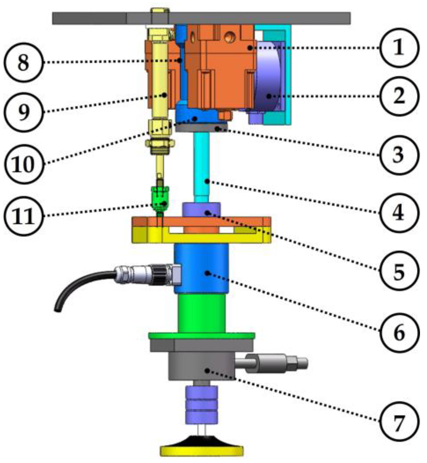
2.1.1. Structure Design of Force-Controlled Actuator

The force-controlled actuator has the function of controlling the normal contact force and increasing the processing compliance in the robot polishing process. For the polishing of plexiglass parts, the force-controlled actuator should have the following functions: (1) It can detect the contact force and ensure the output of a constant small contact force. (2) It has a certain degree of stretching function. (3) It can measure the spatial pose of robot force control actuator. (4) Different polishing tools can be installed. (5) The force-controlled actuator should have a certain amount of stability and anti-interference.
Figure 1 is the structure diagram of the force-controlled actuator. The key components mainly include the cylinder, two electrical proportional valves, ball splines, guiding device, expansion sleeve, floating connector, force sensor and tilt sensor. Among them, the cylinder is the driving element. The two electrical proportional valves control the air pressure in the rodless chamber and the rod chamber according to the control signal, and control the output force of the force-controlled actuator by controlling the pressure difference between the rodless chamber and the rod chamber. The ball spline and the guiding device are matched as the displacement execution structure. The friction force of the ball spline is small and can withstand large torque. On the one hand, the displacement execution structure ensures that the device only moves in the axis direction, on the other hand, it bear the overturning moment and torque acting on the force-controlled actuator. The ball spline and the lower plate are connected by the expansion sleeve, which is simple and reliable. The cylinder and the lower plate are connected by a floating joint. The floating joint can improve the problems of cylinder eccentricity and bad balance accuracy, and reduce the wear of the cylinder piston and increase the service life of the cylinder. The force sensor is used to measure the axial contact force in the polishing process, and the tilt sensor is used to measure the spatial pose of the force-controlled actuator.

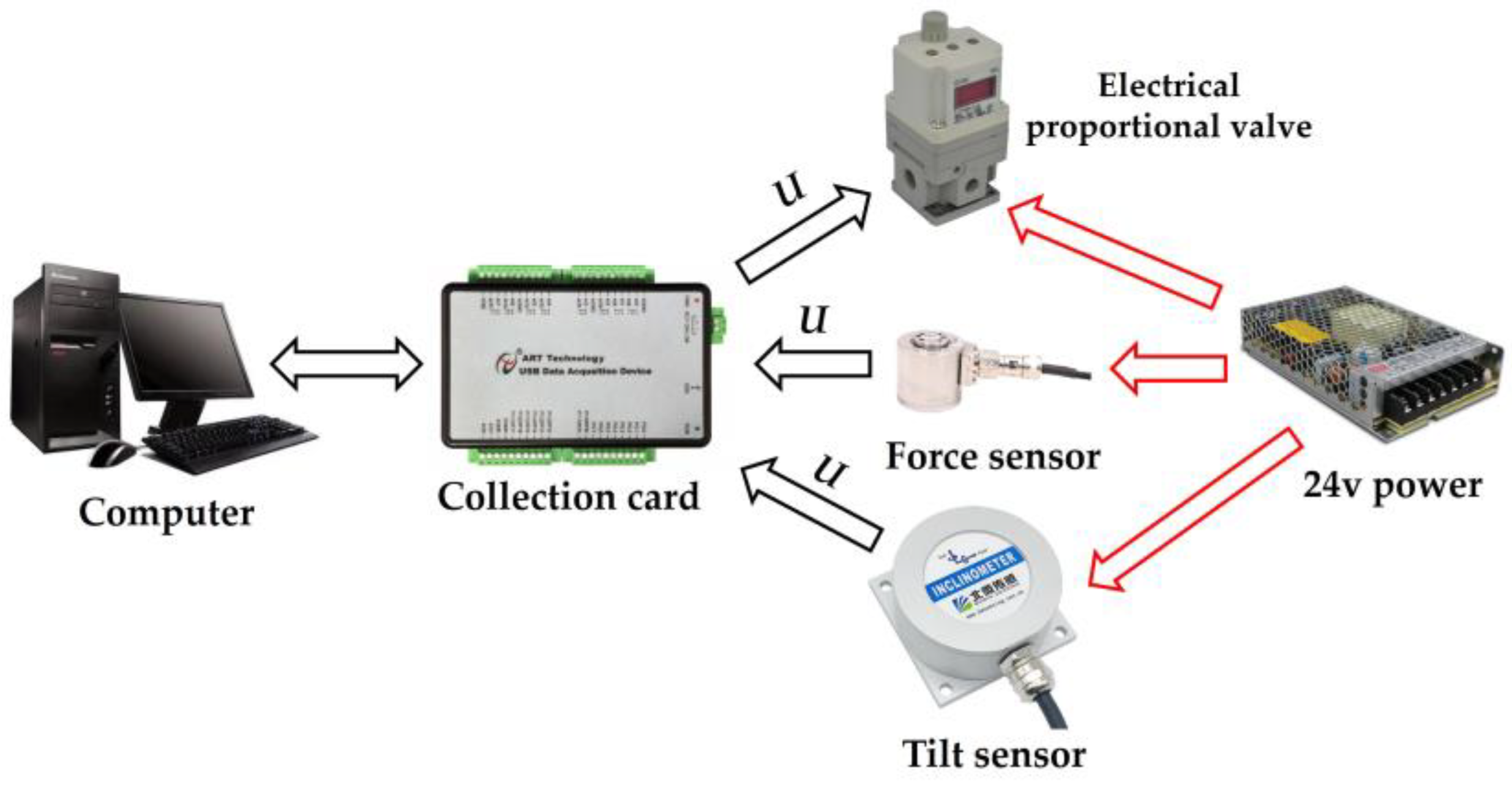
2.1.2. Circuit Communication Design of Force-Controlled Actuator

Figure 2 is the circuit communication diagram of the force-controlled actuator. The data acquisition card uses the USB3133A of ART Technology. The USB3133A acquisition card supports 16 RSE/NRSE channel or 8 channel DIFF analog input, 2 channel analog synchronous output, 16 channel programmable I/O, channel multifunction counter. The output signals of force sensor and tilt sensor are voltage analog signals. The control signal that the electrical proportional valve can receive is a voltage analog signal. The output signal cable of the force sensor and the tilt sensor is connected with the analog input channel of the data acquisition card. When the force sensor is subjected to pressure, the voltage analog signal will be generated, and the voltage analog signal will be output to the data acquisition card through the data transmission cable. The tilt sensor converts the spatial pose data into voltage analog signal and outputs it to the data acquisition card through the data transmission cable when it is powered on. The data acquisition card transmits all the obtained signals to the computer through the USB cable. The computer calculates the voltage signal that should be output to the electrical proportional valve according to the designed algorithm program, and outputs the voltage signal to the data acquisition card through the USB cable. Then, the data acquisition card transmits the voltage analog signal to the electrical proportional valve through the data transmission cable, and the electrical proportional valve outputs the corresponding air pressure according to the received voltage analog signal.
The force sensor, tilt sensor and electrical proportional valve are all powered by a 24 V regulated power supply. The computer supplies power to the data acquisition card via USB cable. Table 1 is the model and description of data acquisition card, sensor, electric proportional valve and cylinder used in the force-controlled actuator.

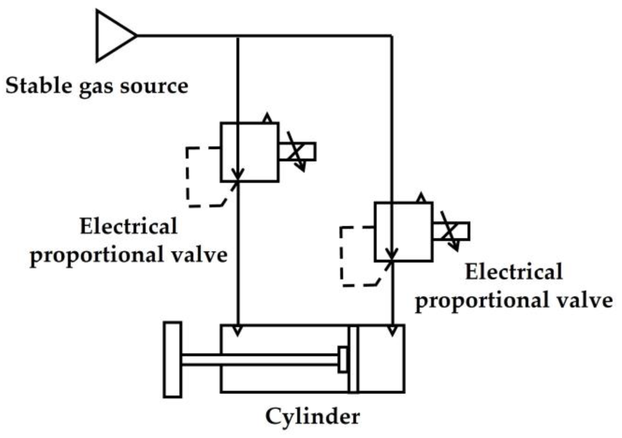
2.1.3. Air Circuit Design of Force-Controlled Actuator

Figure 3 is the air circuit design diagram of the force-controlled actuator. The air compressor provides compressed air and enters two electrical proportional valves through the air pipe. The air outlet of the two electrical proportional valves is connected with the rodless chamber and the rod chamber of the cylinder through the air pipe. The electrical proportional valve controls the air pressure difference between the rodless chamber and the rod chamber according to the control signal used to control the cylinder output force.

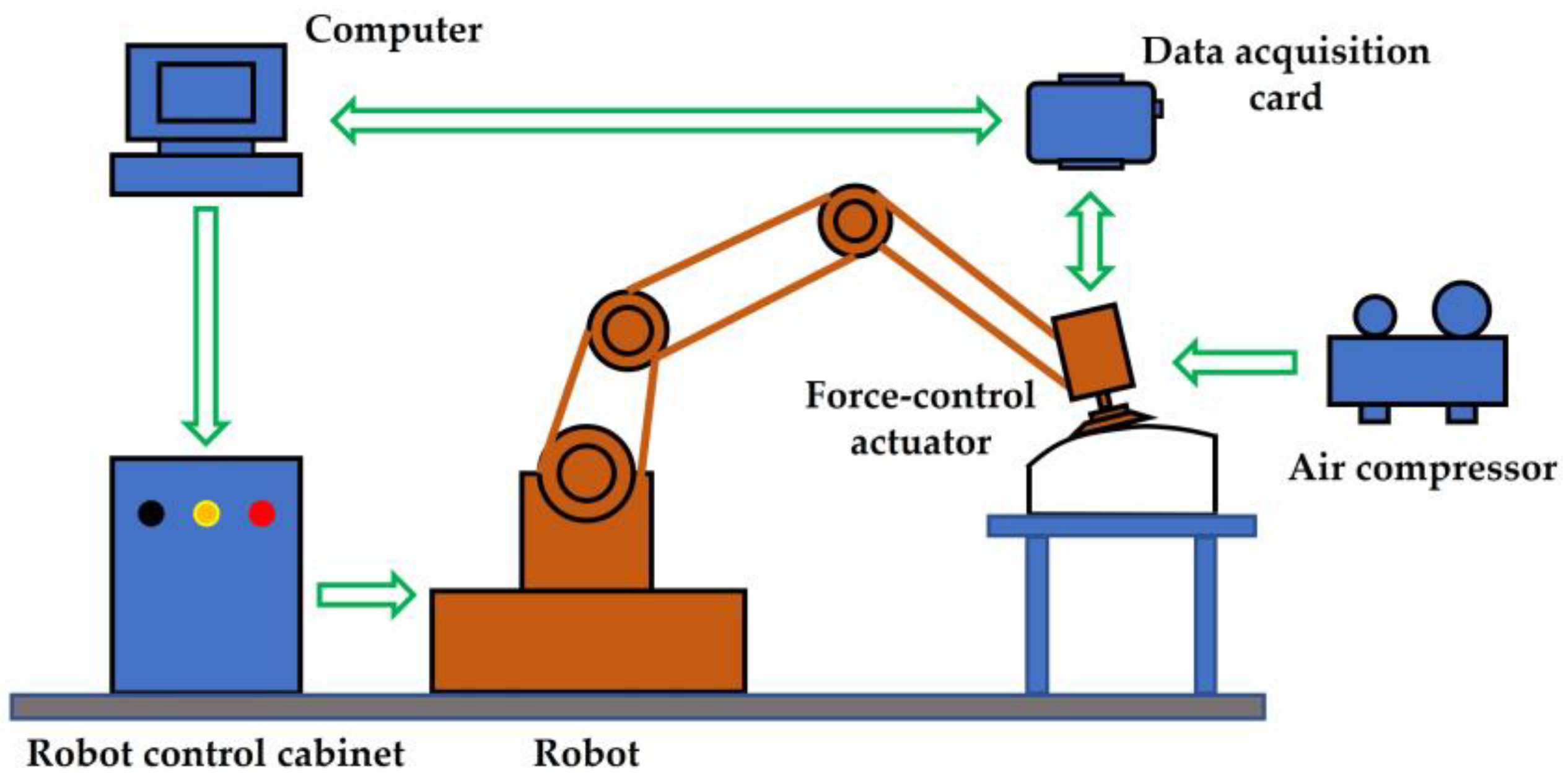
2.2. The Establishment of Robot Automatic Polishing System

In order to realize the automatic polishing of complex curved plexiglass parts, a robot polishing system with force-controlled actuator is established. The system is mainly composed of a six-degree-of-freedom industrial robot and its robot control cabinet, force-controlled actuator, data acquisition card, computer and air compressor.
Figure 4 is the workflow diagram of the robot automatic polishing system. The robot polishing process is as follows:
Firstly, the polishing path program is obtained by CAD/CAM software. Then, the robot off-line programming software converts the polishing path program into a robot polishing path program. After that, the air compressor is run to provide compressed air for the force control actuator, and the fuzzy PID controller is run on the computer and the target value of the contact force is set. At this time, the computer will output the control signal to the two electrical proportional valves, and preset a pressure value for the two electrical proportional valves, respectively, so that the cylinder has a certain tension between the end cover and the polishing tool. Then, the robot control cabinet runs the program. The robot runs according to the planned pose, path and speed. The polishing tool moves on the surface of the curved part under the drive of the robot. At this time, the force sensor and the tilt sensor transmit the collected signal to the computer through the data acquisition card. According to the fuzzy PID control algorithm, the computer obtains the corrected voltage signal after calculation. The correction voltage signal is transmitted to two electrical proportional valves through the data acquisition card. The two electrical proportional valves ensure that the force-controlled actuator outputs a constant normal contact force by adjusting the output force of the cylinder.

3. Establishment of Mathematical Model of Force-Controlled Actuator

After receiving the control signal, the electric proportional valve will output the corresponding air pressure to the two air chambers of the cylinder, and then the cylinder will output the corresponding force. The electric proportional valve and the cylinder are connected by an air pipe. Therefore, it is necessary to establish mathematical models for the process of compressed air flowing through the electrical proportional valve, cylinder and air pipe.

3.1. Modeling the Process of Compressed Air Flowing through the Electrical Proportional Valve

The flow rate of the inlet port of the electric proportional valve is related to the pressure of the inlet port, the outlet port and the opening of the valve port. From the Sanville flow formula [30]:
q = { A P u T K R c ( 2 k 1 ) ( k + 1 k 1 ) , ( 0 P a P u 0.518 ) C f A P u T K R c ( 2 k 1 ) ( P a P u ) 1 K 1 ( P a P u ) K 1 K , ( P a P u > 0.518 )
In the formula, q is the air flow into the electrical proportional valve, P a is the inlet pressure, P u is the outlet pressure, A is the effective area of the electrical proportional valve port, K is the adiabatic coefficient, C f is the flow parameter of the electrical proportional valve orifice, T is the absolute temperature, and R c is the ideal air constant. It can be seen from Formula (1) that when the inlet pressure and the air temperature in the electrical proportional valve are constant, the air flow into the electrical proportional valve is only related to the effective area of the valve port, and the effective area of the valve port is related to the control voltage of the electrical proportional valve. The air flow at the valve port affects the outlet pressure, so it can be considered that the flow formula is a function of the control voltage u and the outlet pressure P u of the valve port. Thus, the simplified flow formula is:
q = f ( u , p u )
When the control voltage u approaches zero, it can be expressed by a linear formula:
Δ q = k 1 Δ u + k 2 Δ p u

3.2. Flow Model of Connecting Air Pipe

The air output from the electric proportional valve flows through a section of air pipe into the working chamber of the cylinder. It is assumed that the air pipe is an ideal circular pipe, and the air flowing through the air pipe is laminar, ignoring the flow loss at the interface of the electrical proportional valve and the air pipe. According to Anderson theory, there is:
q = k 3 ( p u p d )
where q is the mass flow rate of the air in the air pipe, P u is the pressure at the air pipe inlet, and P d is the pressure at the air pipe outlet, k 3 = ρ a D 2 32 μ A L . where ρ a is the average density of the air, D is the inner diameter of the air pipe, μ is the viscosity coefficient of the air, and A is the cross-sectional area of the air pipe.
According to Equation (5), the air flow increment model in the trachea can be obtained:
Δ q = k 3 ( Δ p u Δ p d )

3.3. Cylinder Mass Flow Equation

The compressed air output by the electrical proportional valve flows through the air pipe into the cylinder. Assuming that the air in the cylinder is an ideal amount of air, the air pressure and temperature in the cylinder are uniform, and the cylinder is considered to be closed without leakage. According to the ideal air state equation, there are:
p d = ρ d R c T d
In the formula, P d is the air pressure in the cylinder chamber, ρ d is the air density in the chamber, and T d is the thermodynamic temperature of the air in the chamber.
The mass flow q is equal to the change rate of the air mass m in the chamber, and then:
q = d m d t = d ( ρ d V ) d t
Bringing Equation (6) into Equation (7), we can obtain:
q = V d R c T d ( d P d d t + P d V d d V d d t P d T d d T d d t )
Assuming that the temperature T d and initial temperature T s in the air flow process satisfy the adiabatic process, there is:
T d = T s ( P d P s ) k 1 k
Derivation on both sides of the equal sign of Equation (9), and then bring Equation (8), the flow model in the cylinder chamber can be obtained:
q = 1 k V d R c T d d P d d t

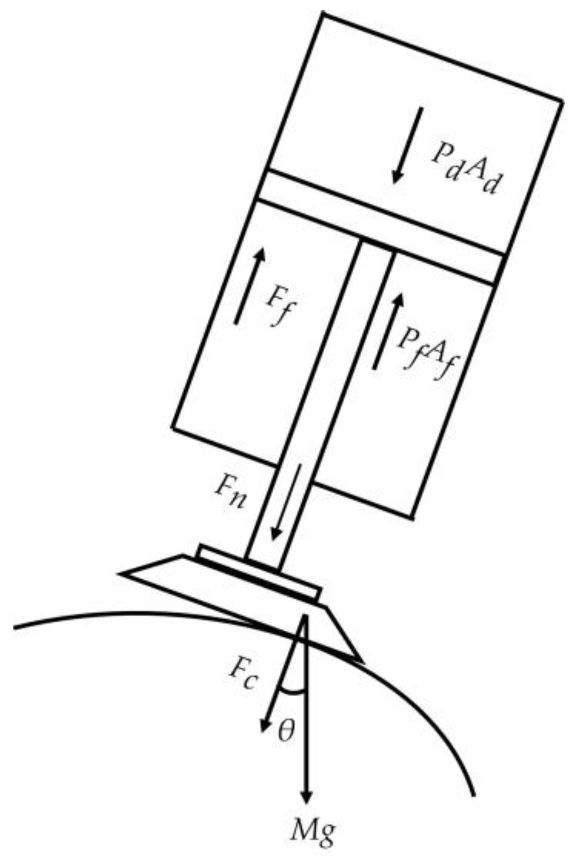
3.4. Force Balance Equation of Force-Controlled Actuator

Figure 5 is the force analysis diagram of the force-controlled actuator. According to Newton’s second law, there is:
M d 2 z d t 2 + C p d z d t + F n + M g c o s θ = P d A d P f A f F f
In the formula, F n is the output force of the cylinder, F f is the friction force, M is the total weight of the connecting part of the cylinder, C p is the viscous damping coefficient, z is the axial displacement distance of the actuator, θ is the angle between the actuator and the direction of gravity.
Since the calculation of the contact force not only considers the cylinder output force but also considers the polishing tool itself gravity, so:
F c = F n + M g c o s θ
Bringing Equation (12) into Equation (11) and ignoring the friction, you can obtain:
M d 2 z d t 2 + C p d z d t + F C = P d A d P f A f F f

3.5. Establishment of Mathematical Model of Force-Controlled Actuator

The Laplace transform of Equations (3), (5), (10) and (13) can be obtained:
Q ( s ) = K 1 U ( s ) + K 2 P u ( s )
Q ( s ) = K 3 P u ( s ) K 3 P d ( s )
Q ( s ) = V d k R c T d s P d ( s )
M s 2 Z ( s ) + C p s Z ( s ) + F c ( s ) = P d ( s ) A d P f ( s ) A f
When the actuator contacts with the workpiece, the contact force is F c , whereas the passive displacement is z . The equivalent stiffness coefficient is K e , then:
F c ( s ) = K e Y ( s )
Combining Equations (14)–(18), the open-loop transfer function of the force-controlled actuator can be obtained:
F c ( s ) U ( s ) = k T d R c K 3 K 1 K e A d [ ( K 3 K 2 ) V d s k T d R c K 3 K 2 ] [ M s 2 + C p s + K e ]
The mathematical model can be used to identify the system, then judge the stability of the system, and preliminarily set the parameters of the control algorithm through simulation, which shortens the debugging time of the force-controlled actuator.

4. Gravity Compensation and Force-Controlled Strategy

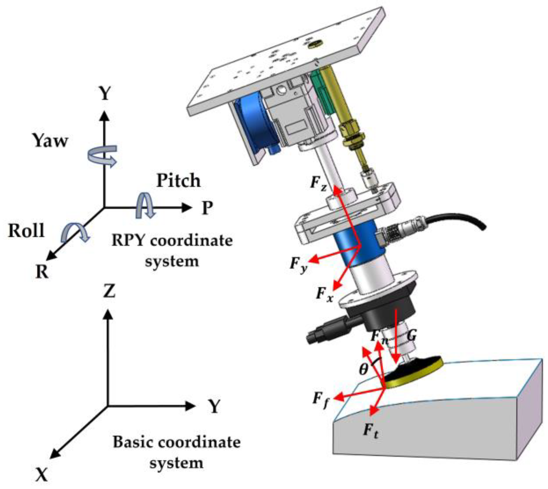
4.1. Force Analysis and Gravity Compensation

In the process of using the robot to polish the curved parts, the space pose of the force-controlled actuator is constantly changing, and the influence of the gravity of the polishing tool on the normal contact force between the polishing tool and the curved part is also constantly changing. In order to obtain accurate real-time contact force, it is necessary to analyze the force of the force-controlled actuator and compensate for the gravity.
Figure 6 is the relationship between the force and the coordinate system in the robot polishing process. F x ,   F y ,   F z are forces in three directions in space measured by a force transducer. F t ,   F f ,   F n are tangential force, feed force and normal contact force when polishing tool contacts curved part. In order to obtain higher processing efficiency and avoid zero rotation speed of the polishing tool during the polishing process, the spindle of the polishing tool is reversely deflected by an angle in the feed direction relative to the normal contact force direction, and g is the gravity of the polishing tool.
The RPY coordinate system in the figure is used to represent the pose of the end force-controlled actuator of the robot, and the RPY angle is a method to represent the end pose of the robot. The calculation method of the RPY angle is as follows: At the initial position, the orientation of the three axes of the RPY coordinate system at the end of the robot is consistent with the orientation of the three axes of the base coordinate system B. Firstly, the RPY dynamic coordinate system of the end-effector of the robot is rotated by an angle α around the x-axis of the base coordinate system B, then the rotation angle β around the y-axis of the base coordinate system B of the robot, and finally the rotation angle γ around the z-axis of the base coordinate system B. Since these three rotations are relative to the fixed base coordinate system B, the corresponding rotation matrix can be obtained:
R P Y ( α ,   β , γ ) = [ c o s γ s i n γ 0 s i n γ c o s γ 0 0 0 1 ] [ c o s β 0 s i n β 0 1 0 s i n β 0 c o s β ] [ 1 0 0 0 c o s α s i n α 0 s i n α c o s α ]
Due to the path planning and the structure of the force-controlled actuator itself, the tangential polishing force F t is always perpendicular to the z-axis of the force sensor, and the feed polishing force F f is very small and can be ignored. Thus, according to the force analysis diagram, the following can be learned:
F z = F n c o s θ G z
where G z is the component force of gravity G in the z-axis direction in the force sensor coordinate system. It can be seen from Equation (21) that the real-time contact force F n can be obtained by calculating G z .
Since the force sensor is fixed on the force-controlled actuator, the force sensor coordinate system and the robot end force-controlled RPY actuator coordinate system coincide. At the initial position, the direction of the three coordinate axes of the robot end force-controlled RPY actuator coordinate system is consistent with the direction of the three coordinate axes of the base coordinate system B. When the robot is used for polishing, after the RPY coordinate system rotates around the base coordinate system B, the tilt sensor measures three angles α , β , γ . Gravity G is expressed as G B = [ 0 0 G ] T in the base coordinate system B. According to Equation (20), the gravity component of gravity G in three directions x , y , z in the force sensor coordinate system can be expressed as:
[ G x G y G z ] = [ c o s γ s i n γ 0 s i n γ c o s γ 0 0 0 1 ] [ c o s β 0 s i n β 0 1 0 s i n β 0 c o s β ] [ 1 0 0 0 c o s α s i n α 0 s i n α c o s α ] [ 0 0 G ]
After calculation:
[ G x G y G z ] = [ c o s α s i n β c o s γ + s i n α s i n γ c o s α s i n β s i n γ + s i n α c o s γ c o s α c o s β ] G
The value of G z is calculated to be G c o s α c o s β , and then the expression of the real-time contact force F n can be obtained by combining Equations (22) and (23):
F n = F z + G c o s α c o s β c o s θ
The real-time contact force F n is the input value of the controller.

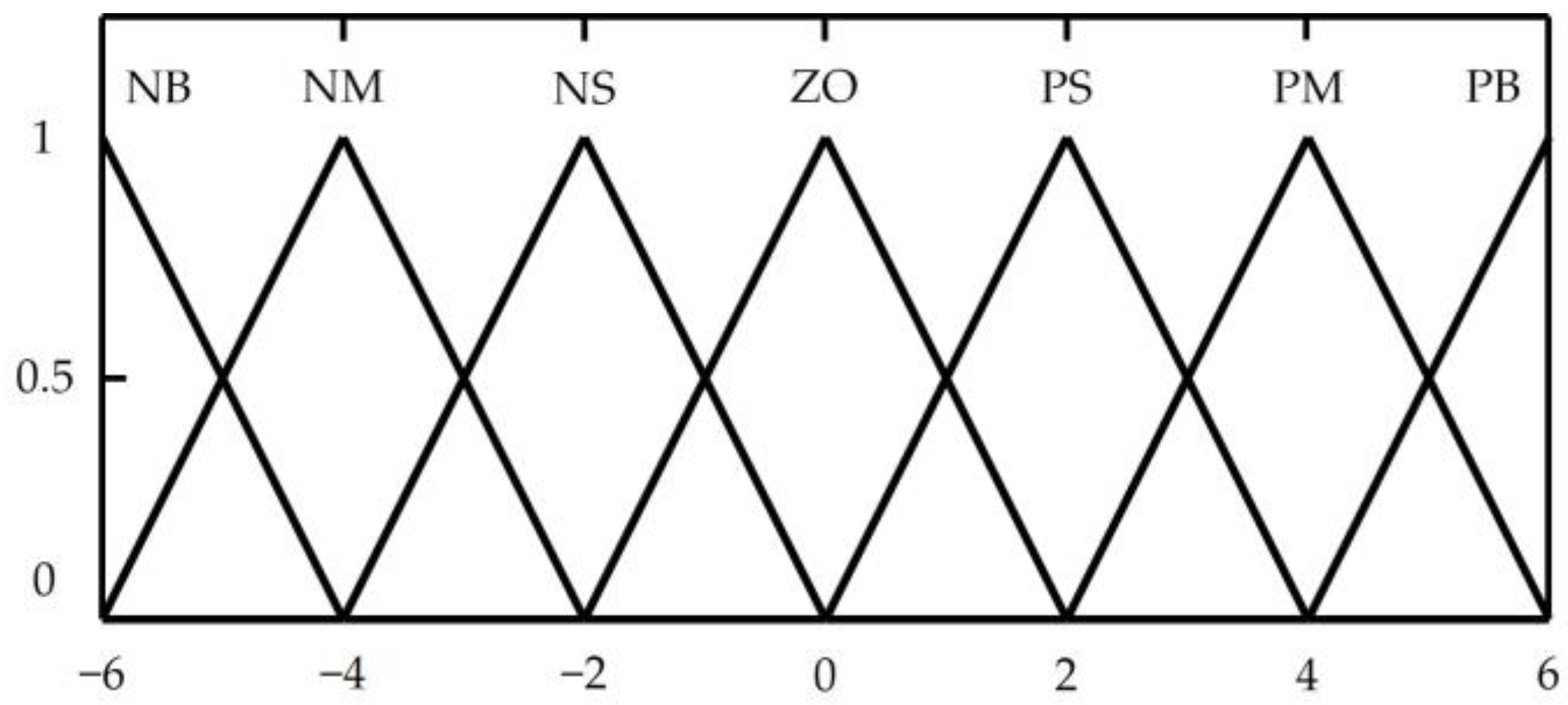
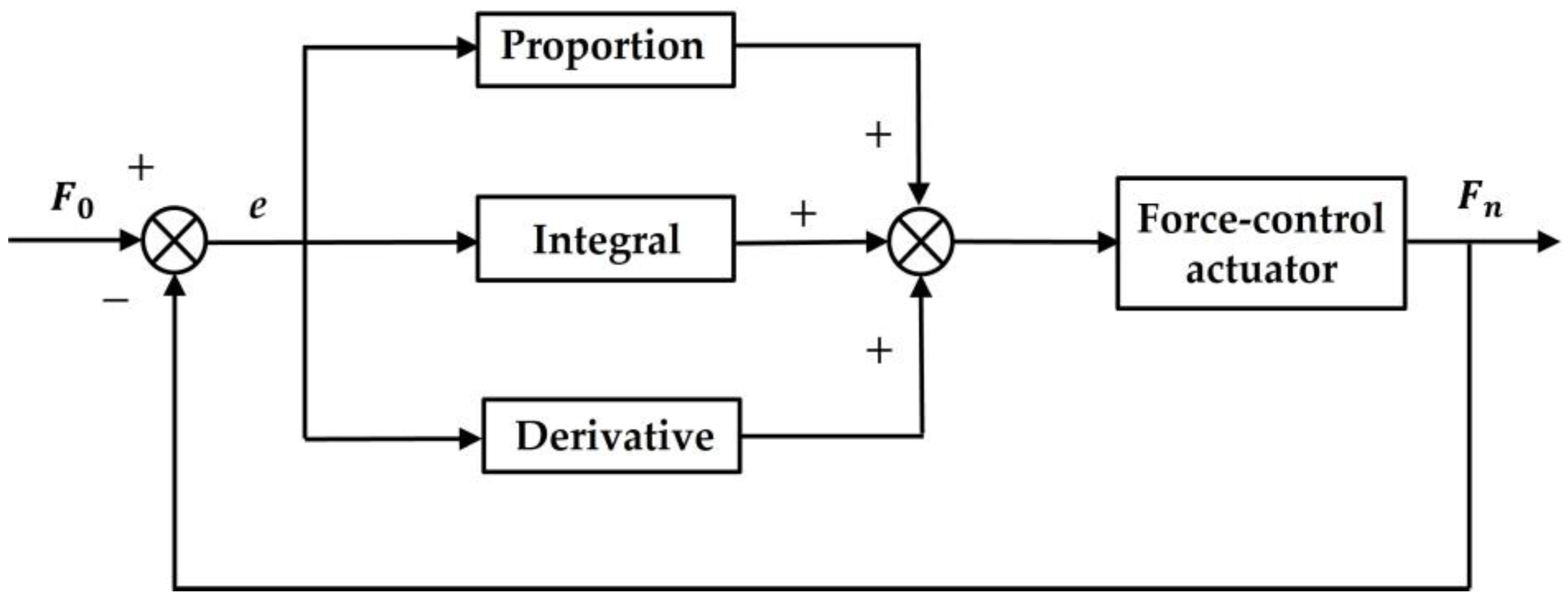
4.2. Force Control Strategy of Force-Controlled Actuator

4.2.1. Force Control Principle of Force-Controlled Actuator

Figure 7 is the workflow diagram of the force control system of the force-controlled actuator, and the specific implementation process of the force control is as follows:
Firstly, the target value F 0 is given before the polishing process. Since the force surface of the force sensor is connected to the polishing tool through the flange, pressure will be generated between the polishing tool and the workpiece during the polishing process, and the pressure on the force sensor will generate a voltage signal. The voltage signal output by the force sensor is transmitted to the computer through the data acquisition card, and the computer processes the voltage signal to obtain the force F z in the z-axis direction measured by the force sensor. At the same time, the tilt sensor converts the measured α , β , γ values into voltage signal output, and the voltage signal output by the tilt sensor is transmitted to the computer through the data acquisition card. Then, the computer calculates the real-time contact force F n according to the gravity compensation algorithm, and compares the target value F 0 with the real-time contact force F n to obtain the error value e and the error change rate e c . According to the fuzzy PID algorithm, the computer calculates the voltage signal u . The electric proportional valve controls the opening of the valve port according to the voltage signal u to output the corresponding air pressure p to the cylinder, and the cylinder converts the air pressure into force output. After that, the force sensor and the tilt sensor collect the signal again. After the gravity compensation calculation, the feedback real-time contact force F n is obtained. The feedback real-time contact force F n is compared with the target value F 0 and calculated, and the error value e and the error change rate e c are obtained. The computer performs the next adjustment. After continuous adjustment, the contact force F n finally meets the tolerance requirement of the target value F 0 .

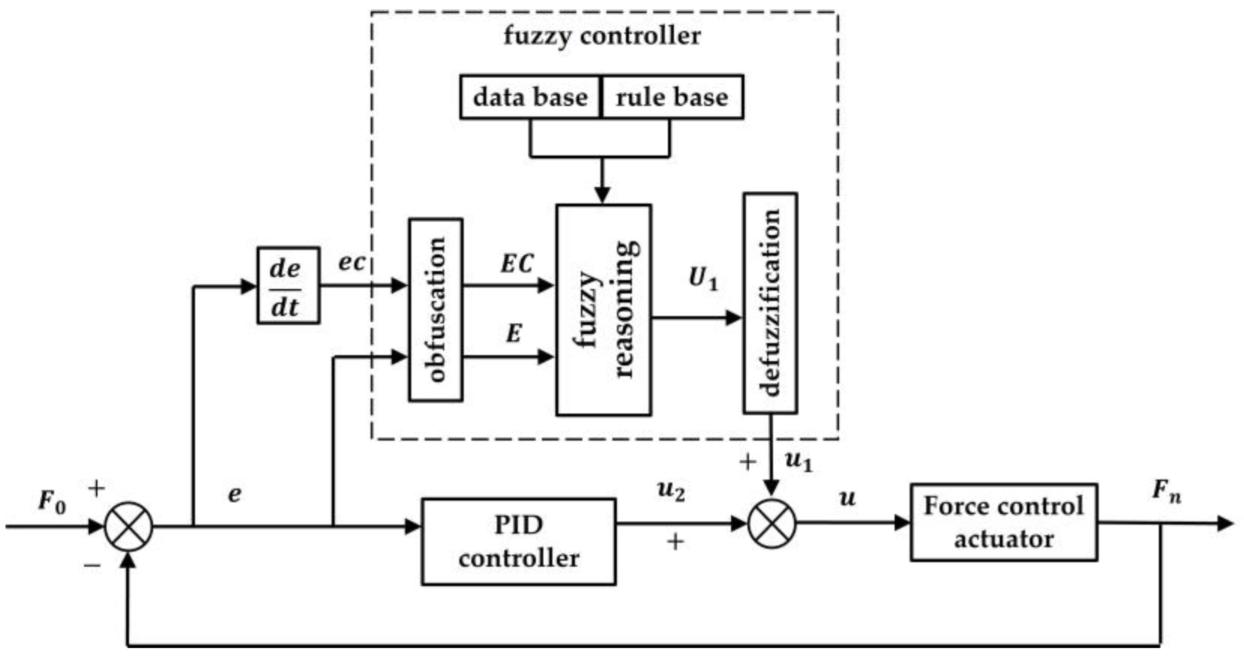
4.2.2. Controller Design

The PID control algorithm is widely used in engineering practice because of its simple algorithm, strong robustness and high reliability. PID control algorithm does not require an accurate mathematical model of the controlled object, and there is no steady-state error. The parameters of the PID control algorithm are fixed after tuning; therefore, the PID control algorithm is only applicable to specific systems under specific working conditions. However, there are some nonlinear factors (such as cylinder friction, displacement changes caused by path planning errors, and impact caused by contact with the workpiece) in the operation of the force-controlled actuator. These nonlinear factors will affect the control effect. The fuzzy control algorithm is mainly used to solve some control problems of complex systems that are difficult to solve by classical control theory and modern control theory. For example, the system has strong nonlinearity, time-varying or cannot be described or described by accurate mathematical model, but the fuzzy control algorithm has a steady-state error in the application process. In summary, the use of one of the above control methods alone will be insufficient. Therefore, a control method combining fuzzy control and PID control is designed, which can not only avoid the steady-state error in the control process, but also eliminate the adverse effects of nonlinear factors on the control effect.
Figure 8 is the Fuzzy PID controller framework diagram, and its specific implementation process is as follows. By comparing the target value F 0 with the contact force F n , the error e and the error rate change rate e c are obtained. The error e and the error rate change rate e c are used as the input values of the fuzzy controller, and the output value is u 1 . The error e is used as the input value of the PID controller, and the output value is u 2 . The fuzzy controller output value u 1 and the PID controller output value u 2 are added to obtain the output value u , and the output value u is the control voltage of the force-controlled actuator.
The design of the fuzzy controller is as follows. The input value e , e c and output value u 1 of the fuzzy system are described by seven fuzzy subsets (Negative big, negative middle, negative small, zero, positive small, positive middle, positive big) denoted by (NB, NM, NS, ZO, PS, PM, PB). The quantitative domain of e , e c and u 1 is set to ( 6 , 4 , 2 , 0 , 2 , 4 , 6 ) . Considering the sensitivity and coverage, each fuzzy subset uses a triangular membership function, which is shown in Figure 9. Assuming that the actual variation ranges of the input values e , e c and the output value u 1 of the fuzzy system are [ a e , b e ] , [ a e c , b e c ] and [ a u 1 , b u 1 ] ,   respectively , and the quantitative domain is [ 6 , 6 ] , then their respective quantization factors k e , k e c and k u 1 can be set as:
k e = 12 b e a e , k e c = 12 b e c a e c , k u 1 = 12 b u 1 a u 1
Fuzzy rules express the relationship between system input and output. The selection of fuzzy rules directly affects the dynamic performance and steady-state performance of system control. The rule base of the fuzzy controller is established according to the experimental experience:
When e is large, regardless of the value of e c , the output value should be increased to eliminate the error;
When e is small or equal to 0, in order to prevent excessive overshoot and make the system fast and stable, it is necessary to determine the change of output value according to e c . If e c is positive, the output value should be increased to suppress the increase of error. If e c is negative, a smaller output value is taken because the error is decreasing. Table 2 is the established fuzzy control rule table.
The above fuzzy rules are transformed into the corresponding fuzzy rule language as follows:
( 1 )   if   ( e   i s   NB )   and   ( e c   i s   NB )   then   ( u   i s   NB ) ( 2 )   if   ( e   i s   NB )   and   ( e c   i s   NM )   then   ( u   i s   NB ) ( 49 )   if   ( e   i s   PB )   and   ( e c   i s   PB )   then   ( u   i s   PB )
According to the fuzzy rules of the first statement, the output value is u 1 . Similarly, the output values u 2 , u 3 , , u 49 are obtained from other statements. Since the relationship between each statement is ‘or’, the output set U of fuzzy control obtained by 49 fuzzy rules is:
U = u 1 + u 2 + + u 49
After the fuzzy reasoning decision, the obtained output set is a fuzzy quantity, and then an accurate value, namely the actual output value, needs to be calculated by defuzzification. Commonly used defuzzification methods include weighted average method, center of gravity method, maximum membership degree method, etc. In this paper, the center of gravity method is selected to realize defuzzification. This method is to find the center of gravity of the area surrounded by abscissa and membership function curve, which is the final output exact value of fuzzy reasoning. Therefore, there is:
v 0 =   v μ v ( v ) d v   μ v ( v ) d v
Among them, v 0 is the result of the fuzzy set obtained by the center of gravity method, v is the abscissa of the output domain equal to the membership function, and μ v ( v ) is the membership function. By multiplying v 0 with the output quantization factor k u , the actual control value u 1 is obtained:
u 1 = k u v 0
Figure 10 is the PID controller frame diagram. In the figure, e is the error value calculated by comparing the target value F 0 with the contact force F n . By linear combination of proportional, integral and differential of the error value e , the control quantity u 2 of the controlled object is obtained as follows:
u 2 ( t ) = k p ( e ( t ) + 1 T i 0 t e ( t ) d t + T d d e ( t ) d t )
where k p is the proportional constant, T i is the time constant, and T d is the differential time constant.
The discrete PID differential equation is:
u 2 ( i ) = k p e ( i ) + k i j i e ( j ) + k d [ e ( i ) e ( i 1 ) ]
Among them, k p , k i and k d are proportional constant, integral coefficient and differential coefficient in PID controller.
The role of the proportional part is to reduce the error quickly when there is an error between the target value and the actual measured value. The larger the value of k p , the faster the response speed of the system, but the overshoot of the system will also increase, and the excessive value of k p will also cause the control system to oscillate. The function of the integral part is to eliminate the steady-state error. The larger the value of k i , the stronger the integration effect, but it will reduce the response speed of the system. Too high k i value can also cause oscillation of the control system. The differential part has the effect of suppressing errors. The larger the value k d , the stronger the differential effect, and can improve the response speed and reduce the system oscillation. However, a too-high value of k d will also make the control system oscillate.
In summary, the expression of the fuzzy PID controller is:
u ( i ) = u 1 + u 2
The output value u of the fuzzy controller is the control signal of the force-controlled actuator.

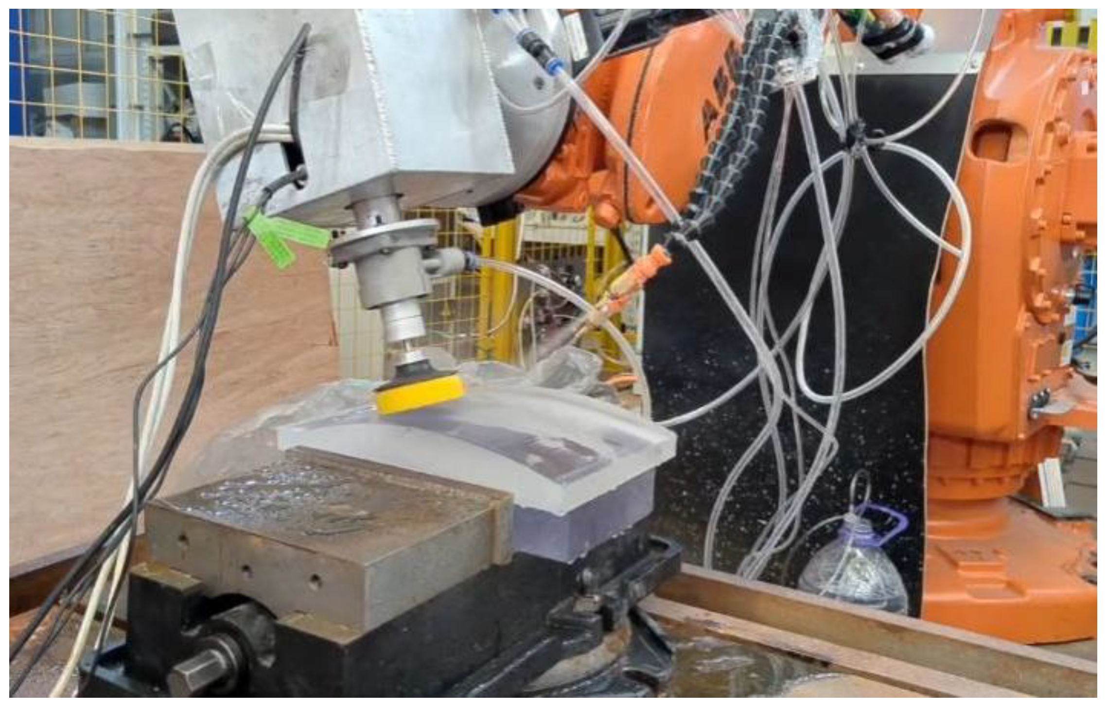
5. Experiment Verification

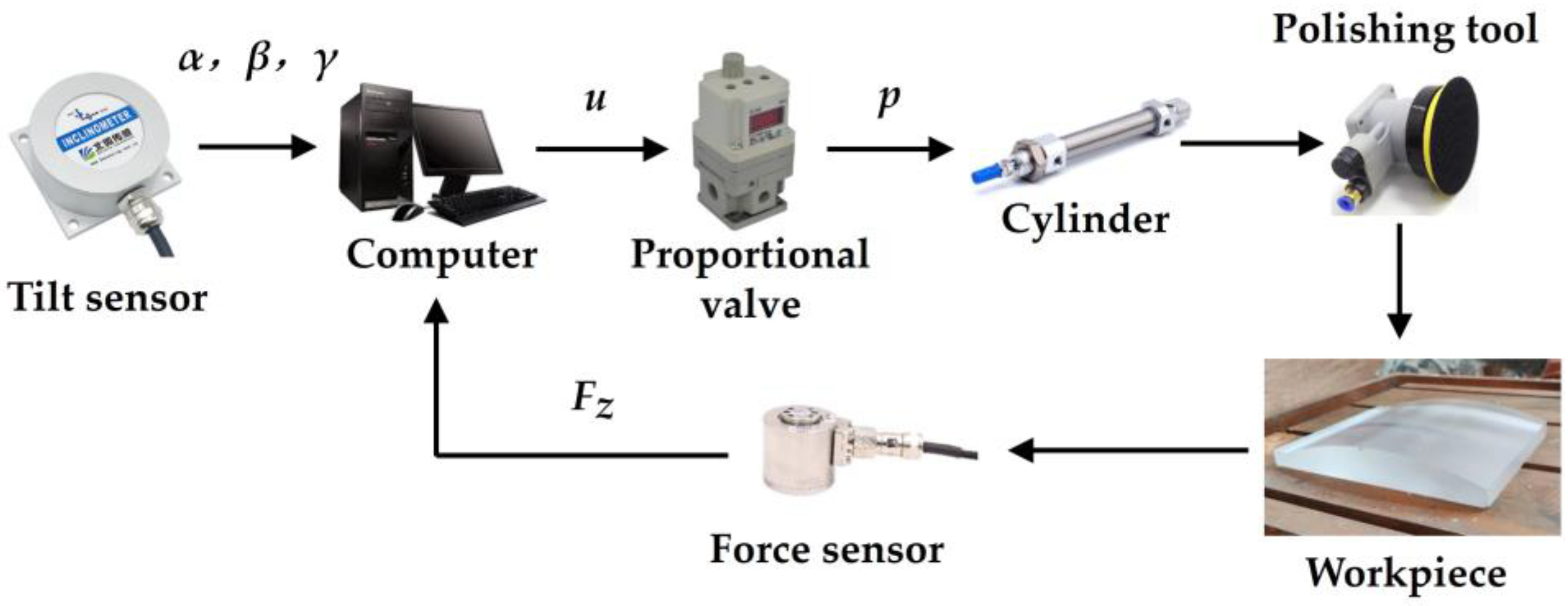
5.1. Experimental Settings

In order to analyze whether the force control accuracy of the force control actuator can meet the processing requirements, and to verify whether the surface quality and optical properties of the complex curved plexiglass parts after polishing meet the process requirements. The polishing experiment of a complex curved plexiglass part was carried out on the industrial robot ABB IRB 6660-205/1.9 using the force-controlled actuator. Figure 11 is the polishing process diagram of the complex curved plexiglass part. Figure 12 is surface effect diagram of the complex curved plexiglass part after milling. The size of the curved transparent part is 250 × 200 × 20 mm. It can be seen from Figure 12 that the complex curved plexiglass part after milling has very bad surface quality and optical performance.
Because the plexiglass material has temperature sensitive characteristics, in order to prevent the surface of the plexiglass workpiece from being burned and damaged, the contact force target value is set to 2.5 N, and the water spray is maintained during the polishing process. Table 3 is the planning table of the polishing process. Firstly, 400 # sandpaper is used to remove the milling cutter marks, then 1000 # and 3000 # sandpaper is used to polish, and finally the wool pad and polishing liquid are used together as the final polishing process. Other polishing experimental parameter settings are shown in Table 4.

5.2. Results and Verification

In order to obtain the force control accuracy of the force-controlled actuator, the data acquisition card is used to collect the contact force data during the polishing process of the complex curved plexiglass part. The acquisition cycle of the data acquisition card is 30 ms. Figure 13 shows the change of contact force with time in the process of polishing the complex curved plexiglass part with 400 # sandpaper. From the diagram, it can be seen that the range of contact force is 2–3 N, the force control accuracy of the force-controlled actuator is ±0.5 N, and the force control accuracy meets the processing requirements.
It can be seen from Figure 14 that the word ‘DUT’ can be clearly seen through the complex curved plexiglass part; therefore, the polished curved plexiglass surface has good surface quality and optical properties. Then, the surface roughness of the complex plexiglass curved part was measured by Zygo NewView 9000 3D surface profiler. The measured area was selected as four randomly distributed areas on the surface of the complex plexiglass curved. It can be seen from Figure 15 that the surface roughness of the four regions measured is less than Ra 0.008 μm.

6. Conclusions

In this paper, a robotic automatic polishing system for polishing complex curved plexiglass part is developed, which includes the development of a pneumatic force-controlled actuator. From our research, the following conclusions can be drawn:
(1)
The force-controlled actuator adopts a double-acting cylinder as the driving element and controls the output force by controlling the air pressure difference between the rodless chamber and the rod chamber of the cylinder. In this way, the small contact force can be controlled and the cylinder always works in the optimum pressure range. In addition, the mathematical model of the force-controlled actuator is established by theoretical analysis. The mathematical model is helpful to judge the stability of the system and the initial setting of the control algorithm parameters, so as to shorten the debugging time of the force-controlled actuator.
(2)
In order to eliminate the influence of the gravity of the polishing tool on the contact force control during the polishing process, a gravity compensation algorithm is proposed based on the RPY angle calculation method, so that the controller obtain accurate real-time contact force and improve the force control accuracy. In addition, considering some nonlinear factors in the operation of the force-controlled actuator, fuzzy PID control strategy is adopted which is suitable for nonlinear control system and has no steady-state error.
(3)
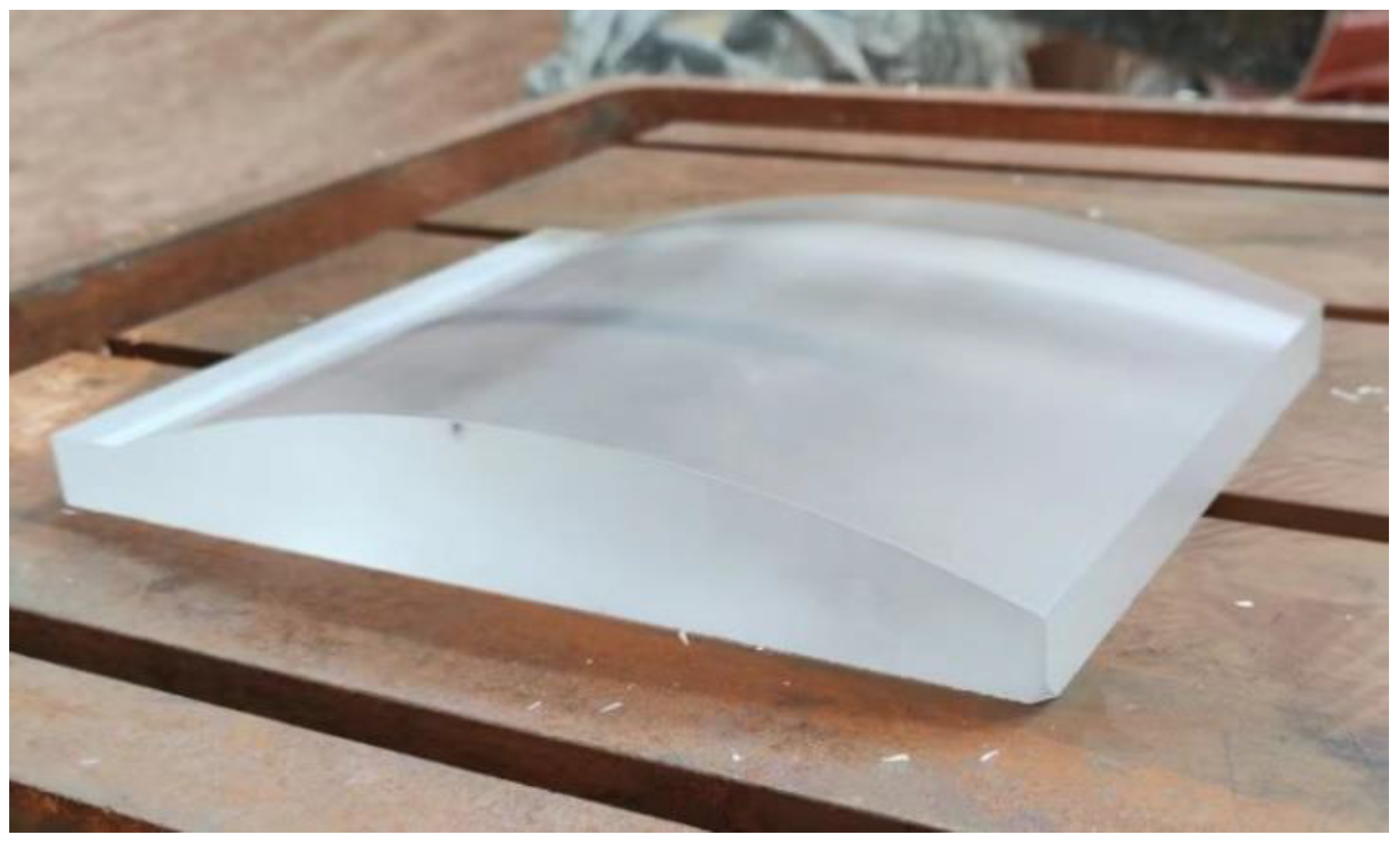
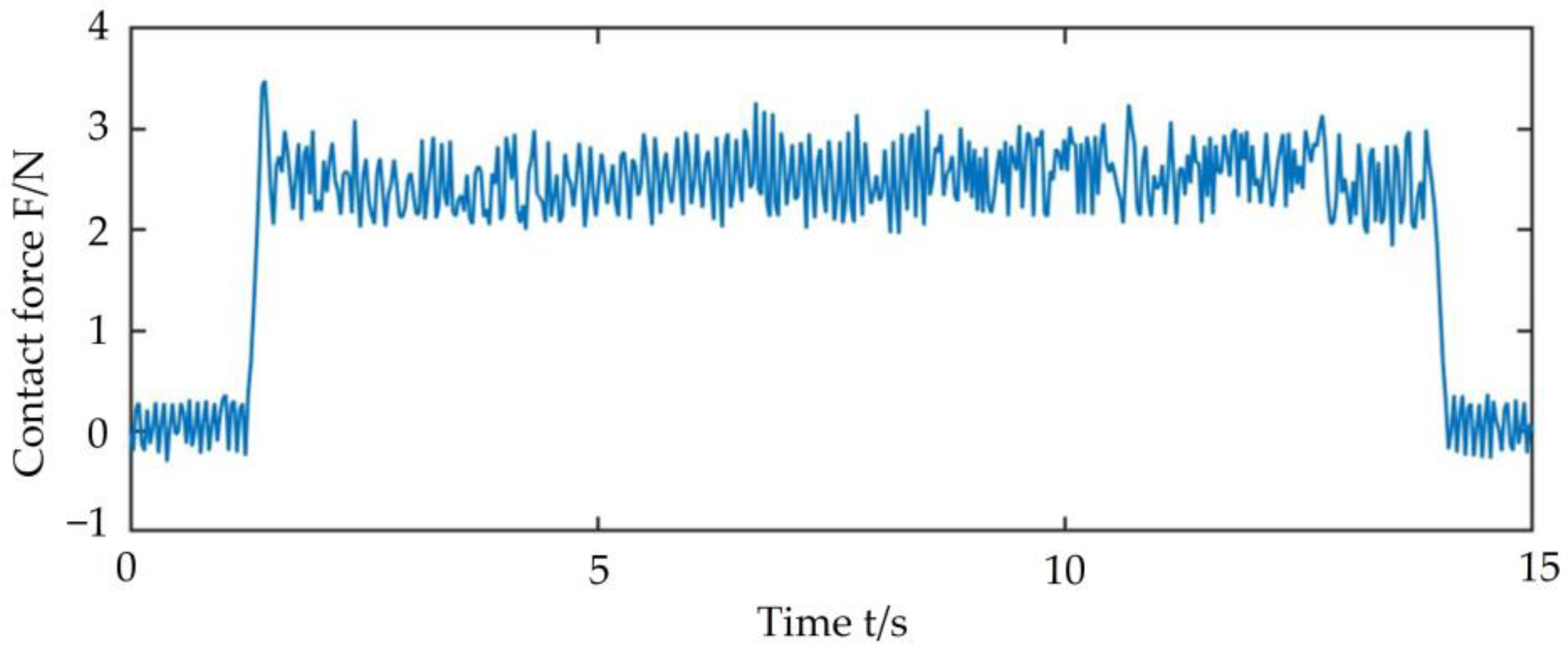
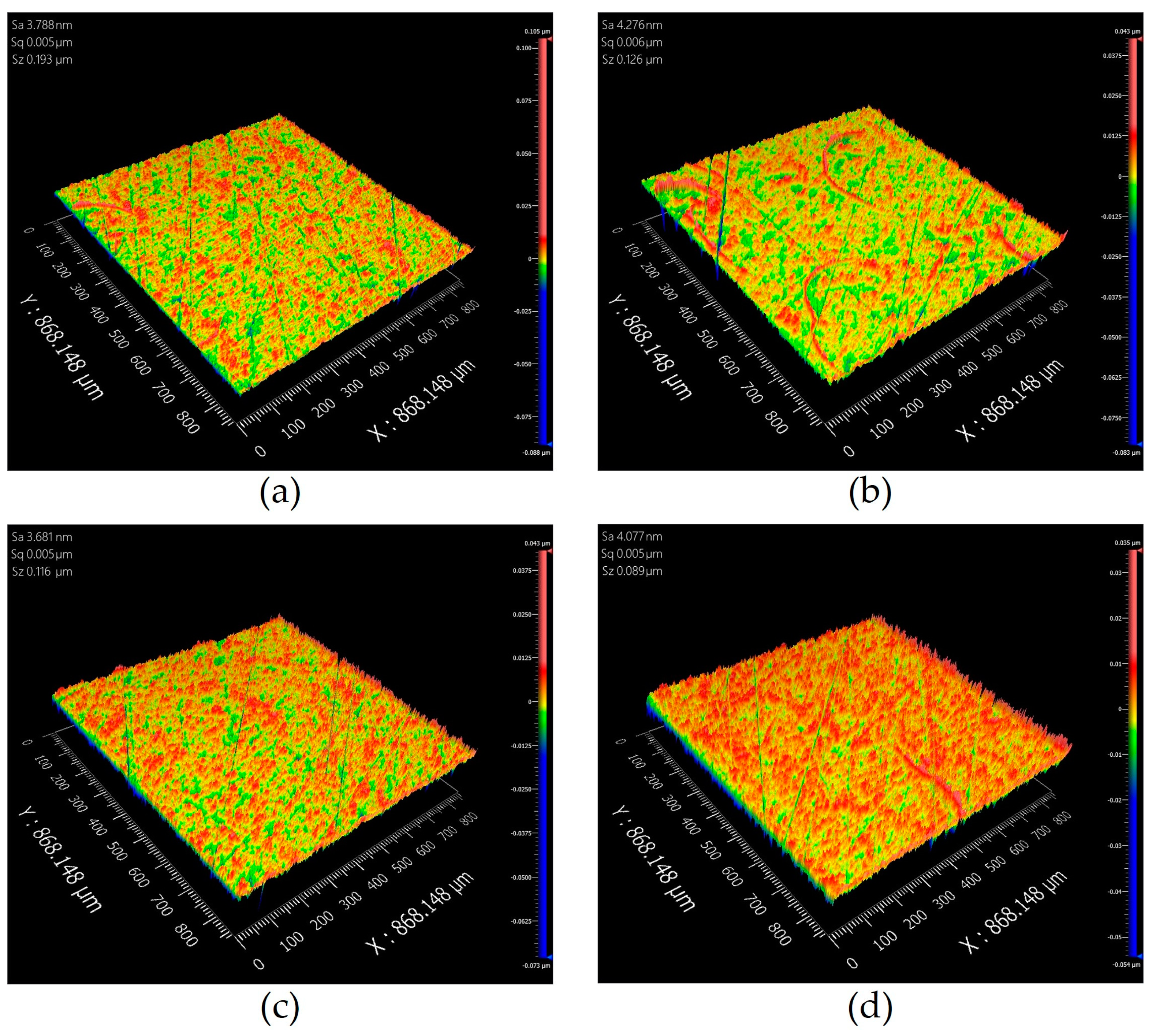
The experimental results verify that the force-controlled actuator has high force control accuracy, and its force control accuracy range is ±0.5 N of the target value. In addition, the polished complex curved plexiglass part has good surface quality and optical properties, and the surface roughness is less than Ra 0.008 μm.
In summary, the proposed robot automatic polishing system with a force-controlled actuator is efficient and practical for the polishing of complex curved plexiglass parts. However, further research is needed in terms of control algorithm optimization, material removal models and optimal process parameters.

Author Contributions

Conceptualization, Y.S.; methodology, X.Z. and Y.S.; software, X.Z.; validation, X.Z. and Y.S.; formal analysis, X.Z. and Y.S.; investigation, X.Z. and Y.S.; resources, Y.S.; data curation, X.Z. and Y.S.; writing—original draft preparation, X.Z.; writing—review and editing, X.Z. and Y.S.; visualization, X.Z.; supervision, Y.S.; project administration, Y.S. All authors have read and agreed to the published version of the manuscript.

Funding

This research was funded by National Natural Science Foundation of China grant number No. 91948203.

Data Availability Statement

Not applicable.

Acknowledgments

This study is supported by the National Natural Science Foundation of China (No. 91948203). The authors thank the anonymous reviewers for their valuable suggestions.

Conflicts of Interest

The authors declare no conflict of interest.

References

  1. Wang, X.K.; Wei, S.C.; Xu, B.S.; Chen, Y.; Yan, X.; Xia, H.H. Transparent Organic Materials of Aircraft Cockpit Canopies: Research Status and Development Trends. Mater. Res. Innov. 2015, 19, 199–206. [Google Scholar] [CrossRef]
  2. Guo, Q.; Wang, W.; Jiang, Y.; Sun, Y. 3D Surface Topography Prediction in the Five-Axis Milling of Plexiglas and Metal Using Cutters with Non-Uniform Helix and Pitch Angles Combining Runout. J. Mater. Process. Technol. 2023, 314, 117885. [Google Scholar] [CrossRef]
  3. Mohsin, I.; He, K.; Cai, J.; Chen, H.; Du, R. Robotic polishing with force controlled end effector and multi-step path planning. In Proceedings of the 2017 IEEE International Conference on Information and Automation (ICIA), Macao, China, 18–20 July 2017; pp. 344–348. [Google Scholar]
  4. Tsukada, T.; Ogawa, S.; Koto, K.; Kakinuma, Y. Development of sensorless force-control-based end-effector for automated robot polishing. In Proceedings of the International Symposium on Flexible Automation, Online, 8–9 July 2020. [Google Scholar]
  5. Sun, Y.; Jia, J.; Xu, J.; Chen, M.; Niu, J. Path, feedrate and trajectory planning for free-form surface machining: A state-of-the-art review. Chin. J. Aeronaut. 2022, 35, 12–29. [Google Scholar] [CrossRef]
  6. Li, Z.; Wang, H.; Zhao, H.; Ding, H. Force Impact Suppression of Contact Transition State in Robot Grinding and Polishing of Industrial Blades. Proc. Inst. Mech. Eng. Part C J. Mech. Eng. Sci. 2022, 236, 7387–7397. [Google Scholar] [CrossRef]
  7. Rooks, B. Robots score at grinding and polishing. Ind. Robot Int. J. 1998, 25, 251–255. [Google Scholar] [CrossRef]
  8. Nagata, F.; Kusumoto, Y.; Fujimoto, Y.; Watanabe, K. Robotic Sanding System for New Designed Furniture with Free-Formed Surface. Robot. Comput. Manuf. 2007, 23, 371–379. [Google Scholar] [CrossRef]
  9. Ryuh, B.S.; Park, S.M.; Pennock, G.R. An Automatic Tool Changer and Integrated Software for a Robotic Die Polishing Station. Mech. Mach. Theory 2006, 41, 415–432. [Google Scholar] [CrossRef]
  10. Huang, T.; Li, C.; Wang, Z.; Sun, L.; Chen, G. Design of a flexible polishing force control flange. In Proceedings of the 2016 IEEE Workshop on Advanced Robotics and Its Social Impacts (ARSO), Shanghai, China, 8–10 July 2016; pp. 91–95. [Google Scholar]
  11. Yu, Z.; Lin, H.I. Development of Robotic Polishing/Fettling System on Ceramic Pots. Int. J. Adv. Robot. Syst. 2021, 18, 17298814211012851. [Google Scholar] [CrossRef]
  12. Domroes, F.; Krewet, C.; Kuhlenkoetter, B. Application and Analysis of Force Control Strategies to Deburring and Grinding. Mod. Mech. Eng. 2013, 3, 11–18. [Google Scholar] [CrossRef] [Green Version]
  13. Wei, Y.; Xu, Q. Design of a New Robot End-Effector Based on Compliant Constant-Force Mechanism. In Proceedings of the IEEE International Conference on Intelligent Robots and Systems, Prague, Czech Republic, 27 September–1 October 2021; Institute of Electrical and Electronics Engineers Inc.: Piscataway, NJ, USA, 2021; pp. 7601–7606. [Google Scholar]
  14. Mohammad, A.E.K.; Hong, J.; Wang, D. Design of a Force-Controlled End-Effector with Low-Inertia Effect for Robotic Polishing Using Macro-Mini Robot Approach. Robot. Comput. Manuf. 2018, 49, 54–65. [Google Scholar] [CrossRef]
  15. Liu, C.H.; Chen, C.C.A.; Huang, J.S. The Polishing of Molds and Dies Using a Compliance Tool Holder Mechanism. J. Mater. Process. Technol. 2005, 166, 230–236. [Google Scholar] [CrossRef]
  16. Huang, H.; Gong, Z.M.; Chen, X.Q.; Zhou, L. Robotic Grinding and Polishing for Turbine-Vane Overhaul. J. Mater. Process Technol. 2002, 127, 140–145. [Google Scholar] [CrossRef]
  17. Wei, Y.; Xu, Q. Design of a New Passive End-Effector Based on Constant-Force Mechanism for Robotic Polishing. Robot. Comput. Manuf. 2022, 74, 102278. [Google Scholar] [CrossRef]
  18. Zeng, G.; Hemami, A. An Overview of Robot Force Control. Robotica 1997, 15, 473–482. [Google Scholar] [CrossRef]
  19. Zhou, H.; Ma, S.; Wang, G.; Deng, Y.; Liu, Z. A Hybrid Control Strategy for Grinding and Polishing Robot Based on Adaptive Impedance Control. Adv. Mech. Eng. 2021, 13, 16878140211004034. [Google Scholar] [CrossRef]
  20. Singh, H.P.; Sukavanam, N. Stability Analysis of Robust Adaptive Hybrid Position/Force Controller for Robot Manipulators Using Neural Network with Uncertainties. Neural Comput. Appl. 2013, 22, 1745–1755. [Google Scholar] [CrossRef]
  21. Li, J.; Guan, Y.; Chen, H.; Wang, B.; Zhang, T.; Hong, J.; Wang, D. Real-Time Normal Contact Force Control for Robotic Surface Processing of Workpieces without a Priori Geometric Model. Int. J. Adv. Manuf. Technol. 2022, 119, 2537–2551. [Google Scholar] [CrossRef]
  22. Du, H.; Sun, Y.; Feng, D.; Xu, J. Automatic Robotic Polishing on Titanium Alloy Parts with Compliant Force/Position Control. Proc. Inst. Mech. Eng. Part B J. Eng. Manuf. 2015, 229, 1180–1192. [Google Scholar]
  23. Xiao, C.; Wang, Q.; Zhou, X.; Xu, Z.; Lao, X.; Chen, Y. Hybrid Force/Position Control Strategy for Electromagnetic Based Robotic Polishing Systems. In Proceedings of the 2019 Chinese Control Conference, Guangzhou, China, 27–30 July 2019; IEEE: Piscataway, NJ, USA, 2019. [Google Scholar]
  24. Li, J.; Guan, Y.; Chen, H.; Wang, B.; Zhang, T.; Liu, X.; Hong, J.; Wang, D.; Zhang, H. A High-Bandwidth End-Effector with Active Force Control for Robotic Polishing. IEEE Access 2020, 8, 169122–169135. [Google Scholar] [CrossRef]
  25. Wu, X.; Huang, Z.; Wan, Y.; Liu, H.; Chen, X. A Novel Force-Controlled Spherical Polishing Tool Combined with Self-Rotation and Co-Rotation Motion. IEEE Access 2020, 8, 108191–108200. [Google Scholar] [CrossRef]
  26. Liu, X.; Zhang, T.; Li, J.; Guan, Y.; Liu, G. A novel end-effector for robotic compliant polishing. In Proceedings of the 2018 IEEE International Conference on Robotics and Biomimetics (ROBIO), Kuala Lumpur, Malaysia, 12–15 December 2018; pp. 1858–1863. [Google Scholar]
  27. He, B.; Chen, Y.; Ma, C.; Yu, M.; Lin, H. A Design of a Constant Force Control Platform based on Air Cylinder. In Proceedings of the 2018 IEEE International Conference on Information and Automation (ICIA), Wuyishan, China, 11–13 August 2018; pp. 1169–1173. [Google Scholar]
  28. Zhang, X.; Chen, H.; Yang, N.; Lin, H.; He, K. A Structure and Control Design of Constant Force Polishing End Actuator Based on Polishing Robot. In Proceedings of the 2017 IEEE International Conference on Information and Automation, Macau SAR, China, 18–20 July 2017; Institute of Electrical and Electronics Engineers Inc.: Piscataway, NJ, USA, 2017; pp. 764–768. [Google Scholar]
  29. Dai, S.; Li, S.; Ji, W.; Sun, Z.; Zhao, Y. Force Tracking Control of Grinding End Effector Based on Backstepping + PID. Ind. Robot. 2022, 49, 34–46. [Google Scholar] [CrossRef]
  30. Tressler, J.M.; Clement, T.; Kazerooni, H.; Lim, M. Dynamic Behavior of Pneumatic Systems for Lower Extremity Extenders. In Proceedings of the 2002 IEEE International Conference on Robotics and Automation, Washington, DC, USA, 11–15 May 2002. [Google Scholar]
Figure 1. Force-controlled actuator structure. 1—Electrical proportional valve (a), 2—Tilt sensor, 3—Ball spline flange, 4—Ball spline shaft, 5—Expansion sleeve, 6—Force Sensor, 7—Polishing Tool, 8—Electrical proportional valve (b), 9—Cylinder, 10—Guiding device, 11—Floating joint.
Machines 11 00446 g001
Figure 2. Circuit communication of the force-controlled actuator.
Machines 11 00446 g002
Figure 3. Air circuit design of force-controlled actuator.
Machines 11 00446 g003
Figure 4. Robot automatic polishing system.
Machines 11 00446 g004
Figure 5. Force analysis of force-controlled actuator.
Machines 11 00446 g005
Figure 6. Force and coordinate system relations.
Machines 11 00446 g006
Figure 7. Principle diagram of force-controlled actuator control system.
Machines 11 00446 g007
Figure 8. Fuzzy PID controller framework diagram.
Machines 11 00446 g008
Figure 9. Triangle membership function.
Machines 11 00446 g009
Figure 10. PID controller frame diagram.
Machines 11 00446 g010
Figure 11. Polishing process of the complex curved plexiglass part.
Machines 11 00446 g011
Figure 12. The actual effect diagram of the curved organic glass parts after milling.
Machines 11 00446 g012
Figure 13. The change in contact force with time in the process of polishing complex curved plexiglass part with 400 # sandpaper.
Machines 11 00446 g013
Figure 14. The actual effect of the complex curved plexiglass part after polishing.
Machines 11 00446 g014
Figure 15. Surface roughness measurement results of four random areas of the complex curved plexiglass part.
Machines 11 00446 g015
Table 1. Model and description of devices used in force-controlled actuators.
ItemsBrand and ModelDescription
Force sensorFIBOS, FA703Three axes force sensor; Range: 100 N in each axis
Tilt sensorBWSENSING, VG320Range: pitch ± 90°, roll ± 180°, heading 360°; Resolution: 0.3°
Data acquisition cardART Technology, USB3133A16 RSE/NRSE channel or 8 channel DIFF analog input; 2 channel analog synchronous output; 16 channel programmable I/O; 2 channel multi-function counter
Electrical Proportional ValveSMC, ITV1050-311LSet pressure range: 0.005–0.9 MPa
CylinderAIRTAC,
MI12-30SCA
Stroke: 30 mm; output force range: rodless chamber 0–79.1 N, rod chamber 0–59.4 N
Table 2. Fuzzy control rules table.
uec
NBNMNSZOPSPMPB
eNBNBNBNMNMNSNSZO
NMNBNMNMNSNSZOPS
NSNMNMNSNSZOPSPS
ZONMNSNSZOPSPSPM
PSNSNSZOPSPSPMPM
PMNSZOPSPSPMPMPB
PBZOPSPSPMPMPBPB
Table 3. Planning of polishing process.
ProcessAbrasive Paper (#)CycleFeed Rate (mm/min)Spindle Speed (r/min)
1400412003000
210002
330002
4Polishing liquid2
Table 4. Parameters setting in polishing process.
ConditionsValues
k p ,   k i ,   k d ,   k e ,   k ec ,   k u 1 0.24, 50, 0.01, 1, 0.1, 0.05
Path interval10 mm
Tilt angle
Sample time30 ms
Abrasive material of sandpaperSiC
Disclaimer/Publisher’s Note: The statements, opinions and data contained in all publications are solely those of the individual author(s) and contributor(s) and not of MDPI and/or the editor(s). MDPI and/or the editor(s) disclaim responsibility for any injury to people or property resulting from any ideas, methods, instructions or products referred to in the content.

