Article

Flow Capacity Optimization of a Squirrel Cage Fan with a New Rounded Rectangle Volute under Size Limitation

Department of Fluid Machinery and Engineering, School of Energy and Power Engineering, Xi’an Jiaotong University, Xi’an 710049, China
*
Author to whom correspondence should be addressed.
Machines 2023, 11(2), 283; https://doi.org/10.3390/machines11020283
Submission received: 19 December 2022 / Revised: 9 February 2023 / Accepted: 10 February 2023 / Published: 13 February 2023
(This article belongs to the Special Issue Aerodynamic Design and Optimization for Turbomachinery)

Abstract

:
Squirrel cage fans (SCFs) are widely used in a variety of household appliances. Due to the restriction on installation size, the design of high-efficiency SCFs with high flow capacities is an important topic. In this study, we proposed a novel rounded rectangle volute profile (RRVP) for the design of compact high-flow SCFs. At first, we used computational fluid dynamics (CFD) to simulate the aerodynamic performances of three SCFs having the same impeller but different volutes, which were the common logarithmic-spiral volute profile, the cutting volute profile, and the RRVP volute at the maximum flow rate working condition. The CFD simulations indicate that the fan with RRVP volute has the highest flow rate at the maximum flow rate working condition. Then, we proposed a parameterization method for the RRVP with 16 control variables. The multiobjective evolutionary algorithm based on decomposition (MOEA/D) and Kriging model was used to optimize the aerodynamic shape of the compact SCF with an RRVP volute. Twenty-three control variables were used in the multiobjective optimization process, including the optimization of the blade angles and the impeller position. Optimization results show that the maximum volumetric flow rate of the optimal SCF with an RRVP volute increases from 147.1 cubic feet per minute (CFM) to 191.1 CFM, and the fan efficiency also increases from 32.21% to 33.5%, compared with the original SCF with the common logarithmic-spiral volute. Two main factors were found to increase the flow capacity and efficiency of the optimal SCF under strict size constrains. First, the RRVP became smooth and large, which reduced the flow loss and increased the flow cross-section; second, the eccentrically mounted impeller of the optimal fan enlarged the flow section near the outlet of the volute.

1. Introduction

Nowadays, various household appliances and HVAC (heating, ventilation, and air conditioning) systems have found wide application in our daily life. Considering the tight installation space, the household appliances and the equipment in the HVAC systems, such as kitchen hoods, vacuum cleaners, and ventilators, must be compact. The squirrel cage fan (SCF), also known as the multiblade centrifugal fan, is found to be suitable in these appliances due to the characteristics of low noise and high flow rate. In general, a high flow rate or a large capacity of the SCF is essential for these appliances. However, the installation space for the SCF is very limited. Therefore, determining how to improve the flow capacity of an SCF with a high flow capacity under a given space constraint has always been a hot topic [1].
In the past, when the computers were not capable of simulating the complicated flow field in the SCF, the laser doppler anemometry was often used to measure the internal flows [2,3,4]. In recent years, the computational fluid dynamics (CFD) method has found wide application in the performance evaluation and aerodynamic design of the SCF, with the aid of powerful computers [5]. The flow path of an SCF is mainly composed of passages through the nozzle, the centrifugal impellor with dozens of strong tip-forward blades, and the nonaxisymmetric volute. Therefore, CFD-based simulations and optimizations played an important role in the improvement of aerodynamic performance of an SCF or the three main components. For example, Gholamian et al. [6] numerically studied the influence of the nozzle size on the fan performance, and discovered that a proper nozzle diameter could improve the inlet flow profile toward the impeller and increase the fan efficiency. Liu et al. [7] proposed a new D-shaped asymmetric input nozzle and discovered that the fan pressure at low flow rates can be increased by 6%. Li et al. [8] studied the effect of blade profiles on the aerodynamic performance of the SCF. They evaluated the aerodynamic behaviors of the single arc and the double arc blades by CFD and discovered that the SCF with double arc blades performed better. Wang et al. [9] found that using continuous curvature radius of the volute profile may significantly improve the aerodynamic performance of the SCF. Wen et al. [10] used an eccentric inlet nozzle and found that it can significantly enhance the aerodynamic efficiency of a small SCF. The final fan had a flow rate increased by 3.5% and an efficiency improved by 1.6%. Nikkhoo et al. [11] showed by their experimental results that the SCF with a conical impeller had a better aerodynamic performance than the one with a cylindrical impeller. Wang et al. [12] investigated the influence of oblique cut on the leading edge of the blade on SCF’s performance and found that a suitable oblique cutting angle could improve the inlet flow conditions and make the performance curve of the fan shift towards the larger flow rates. Generally speaking, the design and optimization of the three components are the practical ways to improve its aerodynamic performance of the SCF.
The aerodynamic optimization of the components of the SCF has been conducted by many researchers by using various optimization algorithms or surrogate models. For instance, Kim and Seo [13] optimized the impeller blade profile of an SCF by using the response surface approach (RSA). Han and Maeng [14] optimized an SCF using an artificial neural network (ANN). Yang et al. [15] optimized the double arc blade profile of an SCF by using the nondominated sorting genetic algorithm (NSGA-II) and achieved a 1.5% improvement in the efficiency at the best efficiency point. Zhou et al. [16] optimized the SCF blades by using the radial basis function network and NSGA-II. Additionally, the Kriging model combined with the parallel infill criterion was used to maximize the efficiency of SCF at the maximum volumetric flow rate point (MVP) and best efficiency point [17,18]. Open-source libraries, such as the Dokota, Solome, and Openfoam, were used to developed a complete automatic optimization process loop for the SCF, and the total pressure rise efficiency was improved by 8.46% [19]. In addition, some new optimization approaches, such as MOEA/D-EGO [20] and K-RVEA [21], were proposed to solve the expensive black box problems, such as the aerodynamic optimization design of SCFs. However, most of the previous investigations were paid on the design and optimization of the conventional SCFs which were not strictly limited by installation sizes.
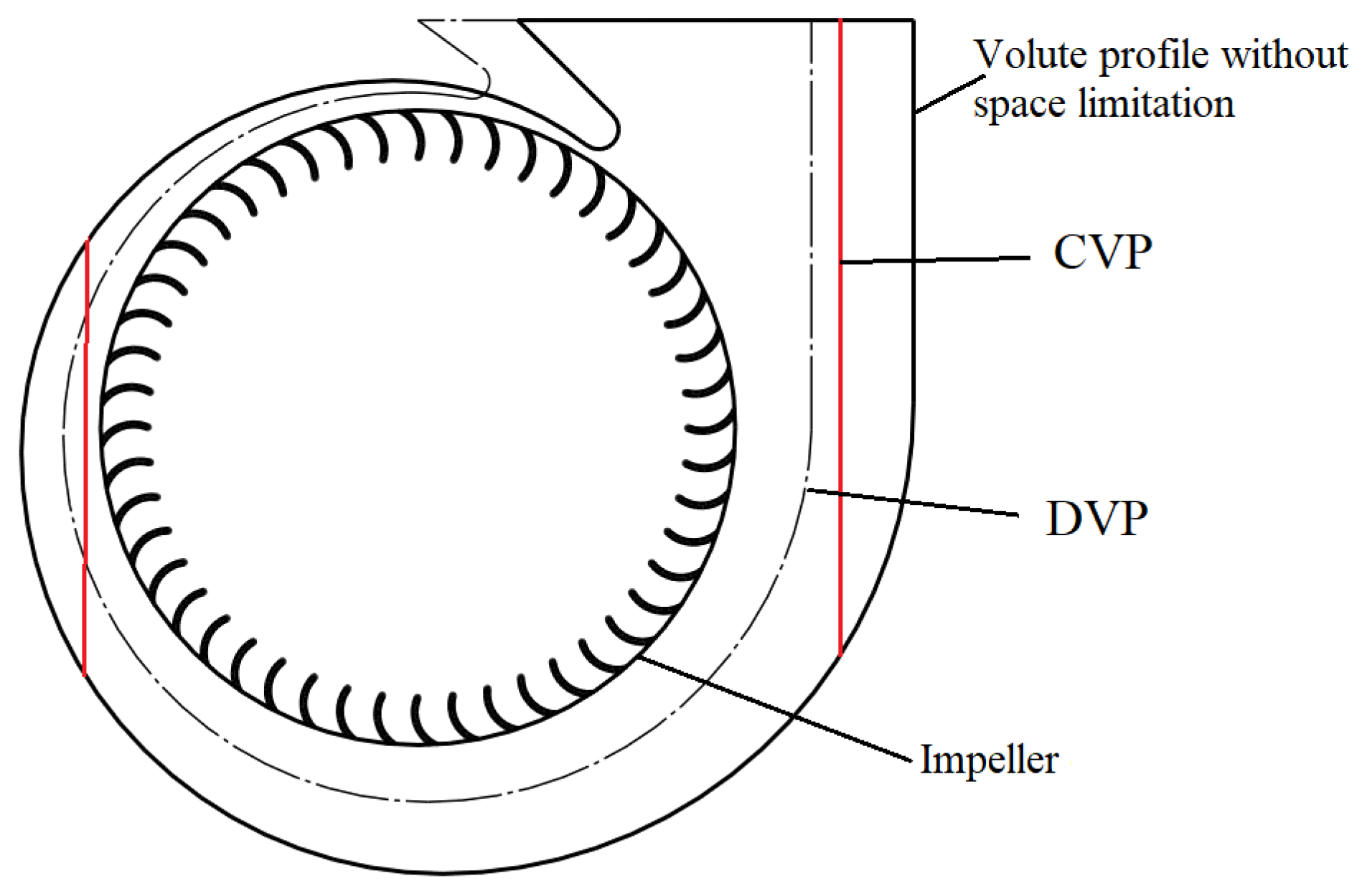
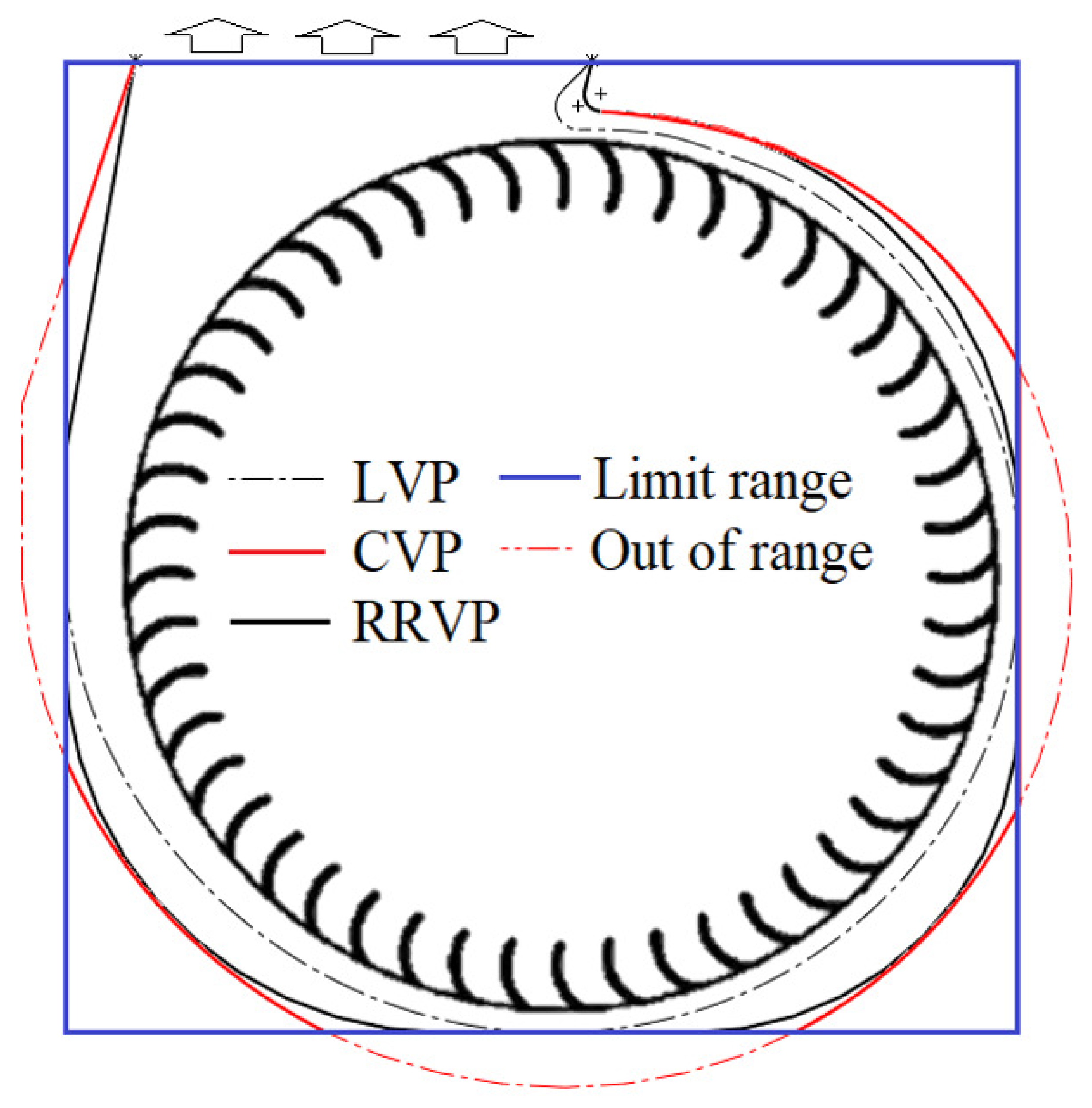
An SCF with a high flow capacity usually needs a relatively large size. In many cases, the size of the common SCF exceeds the installation space. Therefore, design and optimization of an SCF with a constraint for its size have attracted much attention of researchers in this field, and different effective measures have been proposed and applied. For example, the methods of cutting volute profile (CVP) and downsized volume profile (DVP) are often used in such applications, as shown in Figure 1. Wen et al. [22] investigated variations in the performance of an SCF matched with three different volutes, which were the CVP volute, the DVP volute, and a new partial flow volute profile (PVP). The PVP volute had a shape of a circular arc at first and then a spiral curve segment. The investigations showed that the SCFs adopting the PVP or the DVP volute performed better than those having the CVP volute. Jiang et al. [23] investigated and evaluated the influences of the cutting position of a CVP on SCF’s performance and flow fields. Xiao et al. [24] also made a comparison between the SCFs having a CVP volute or having a B-spline curved volute, and discovered that the latter had a better performance. From Figure 1, it can be seen that the CVP will inevitably introduce discontinuous at the cutting positions. The investigations cited above showed that this discontinuity had a significant negative effect on the aerodynamic performance of SFCs, although the CVP has a larger cross-section in the un-cutting part of the volute for the air to flow.
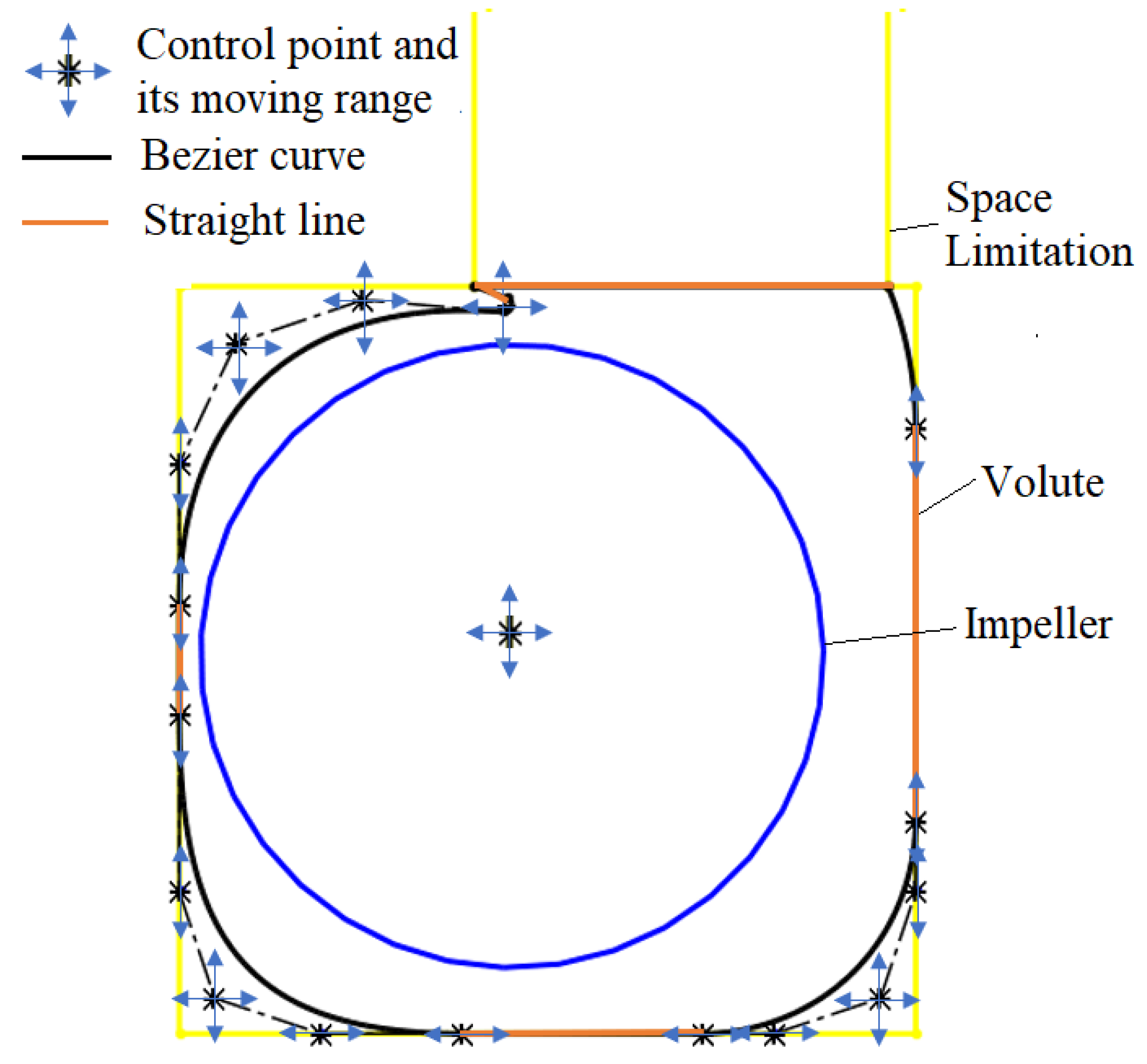
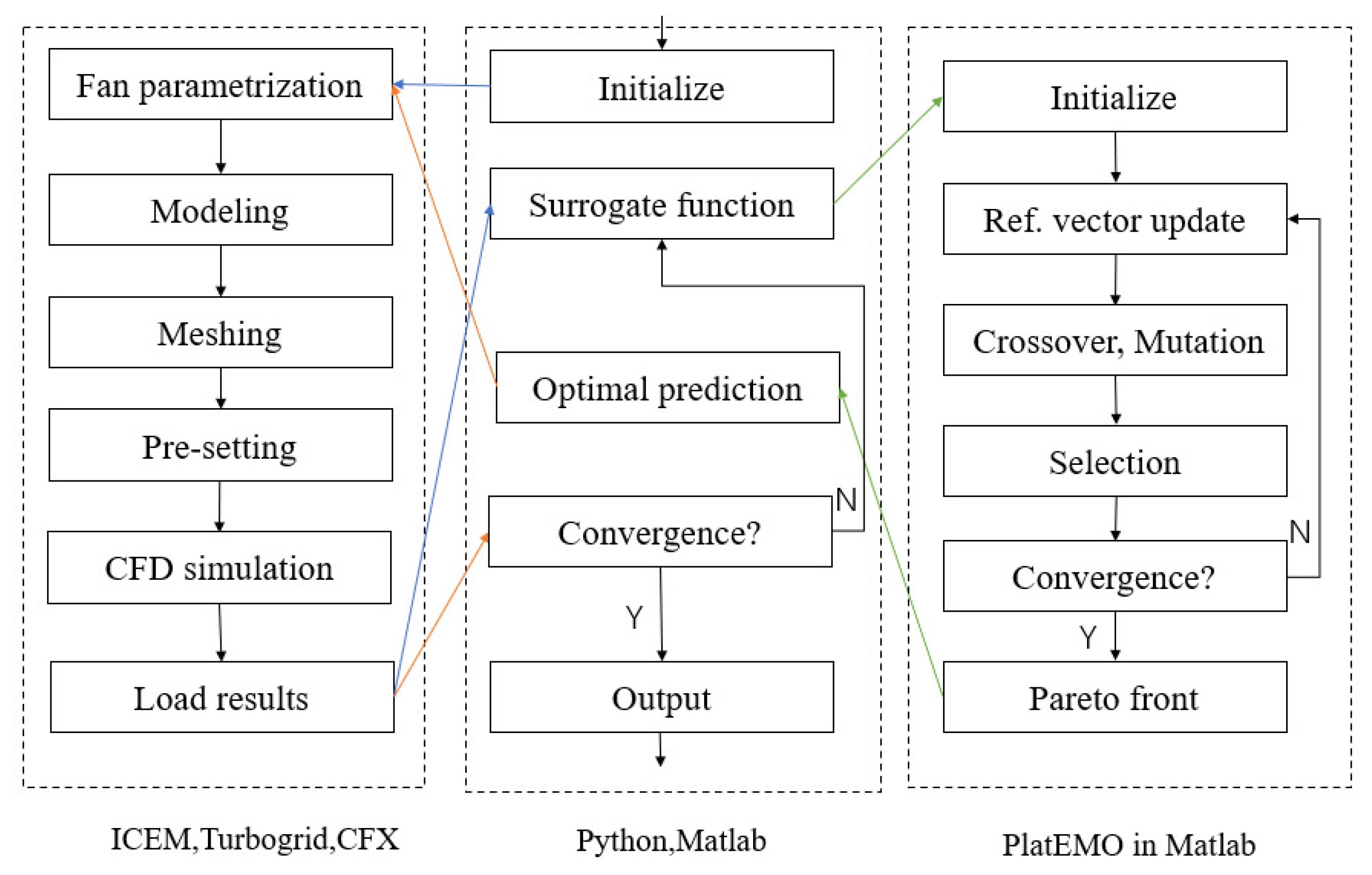
From the above discussion and citations, it is known that an SCF with a high capacity often faces installation limits and the volute has to be deformed either by using a CVP or a DVP. These two types of volutes will either decrease the efficiency or the flow rate of the SCF. Additionally, the past proposed optimization methods were mainly concerned with the SCF without an installation limit. In the present study, a novel rounded rectangle volute profile (RRVP) was proposed to increase the flow rate of space-constrained SCFs. In the meantime, a corresponding parameterization method for the RRVP and optimization method by using multiobjective evolutionary algorithm based on decomposition (MOEA/D) and Kriging model were proposed, to optimize the aerodynamic shape of the compact squirrel cage fan.
In this study, three fans with the same impeller and different volutes were designed and compared: the first one is a logarithmic-spiral volute profile, the second one is a cutting volute profile (as the CVP in Figure 1), and the third one is the proposed volute with an RRVP. The CFD simulations indicated that the fan with the proposed RRVP volute had the most optimal aerodynamic performance. The MOEA/D-EGO algorithm was then used to optimize both the blade and volute profiles, as well as to investigate the interactions between the impeller and volute flow fields.

2. Computational Domain and Models

2.1. Prototype Fan

In this study, a double-entry SCF was adopted as the research object. This double-entry SCF is installed in an over-the-range (OTR) microwave appliance which is a space-saving alternative to a countertop microwave. Figure 2 shows the internal configuration of the microwave. It can be seen that the installation space for this SCF is very limited. Air is suctioned from the air intake at the bottom of the microwave oven and then flows into the SCF from both sides of the microwave oven at the upper and back side of the microwave. As shown in Figure 3, the double-entry SCF consists of two identical single SCFs which are mounted side-by-side (one impeller is black, the other is white) on the shaft of a motor. Therefore, each fan will provide half of the total flow rate. The fan’s efficiency is defined according to the following formula:
η = P t × Q v W total × 100 % ,
where P t is fan total pressure rise, Q v is fan volumetric flow rate, and W total is the shaft power.For this SCF, it is desired that the flow rate be as high as possible at the working condition of zero static pressure rise.This working condition is also known as the maximum volumetric flow rate point (MVP), with the inlet total pressure and the exit static pressure both being 1 atm.
In the performance experiment, the outlet of the fan was connected to the inlet of the test platform and was kept at 1 atm static pressure. The inlet of the fan was exposed to the atmosphere directly, i.e., the inlet total pressure was 1 atm. The configuration of one SCF (the left one from the symmetric plane) is shown in Figure 4. It can be seen that air is inhaled simultaneously from the inlet of the nozzle and from the motor side, and then flows out of the double-entry fan. The impeller of the single SCF is asymmetric with a disk installed inside to mount the impeller on the motor shaft, in addition to the obstruction of the motor on the right. The rated and experimental data of the single SCF at MVP are shown in Table 1. For the fan design, the allowable maximum size (not including the shell thickness) of the fan is 105.5 mm×104 mm×102 mm, and the volute outlet is connected to a fixed 48 mm×102 mm vent, as shown in Figure 5. The experimental flow rate of the prototype at MVP is 144 cubic feet per minute (CFM).

2.2. Computational Domain and Verification of Computational Models

Figure 6 shows the computational domain for the SCF. In the simulating processes, an extension cylinder passage was added to the inlet nozzle on side A, with the side wall of the cylinder being set as the wall boundary and the upper circular surface the inlet boundary. On the motor side, the shape of the electric motor was simplified as a cylinder with a domed end on side B, and a large cylinder with a 3-times diameter of the motor was used to enclose the motor. The side surface of the motor was set as the wall boundary, while the side surface of the outer cylinder was set as inlet boundary. The bottom surface of the outer cylinder was set as a symmetrical boundary, for it was the symmetrical plane of the double-entry SCF (see Figure 3). The heating effect of the motor on the incoming flow was neglected. The total pressure of 1 atm was assigned to the inlet boundaries on the extension passage side and the side surface of the outer cylinder. The impeller region was set as the rotational domain with a rotational speed of 3350 rpm. The interface between the impeller outlet and volute inlet was set as the frozen rotor interface type. The open condition was assigned to the volute outlet boundary, and the outlet static pressure was set to 1 atm.
Figure 7 shows the meshes in the different computational domains of the SCF. Ansys Turbogrid was used to load the blade profile coordinates and to generate hybrid O–H structured hexahedron meshes of impeller (Figure 7c). Unstructured hybrid tetrahedron and hexahedron (near wall) mesh of volute was generated by the ICEM software (see Figure 7e). For the other computational subdomains, i.e., the inlets and outlet, the structured hexahedron meshes stay unchanged during the optimization. All the meshes were generated automatically through script files to complete hundreds of simulation calculations in aerodynamic optimization.
The CFD simulations were performed by using ANSYS CFX 19.0. The three-dimensional steady incompressible viscous flow is solved by adopting the Reynolds-averaged Navier–Stokes (RANS) equations with a k- ω -based shear stress transport (SST) model, in which the k- ω formulation was used near the wall and the k- ϵ formulation was applied in the mainstream [25]. The SST model is more accurate and robust than the standard k- ω or k- ϵ models [26]. It also proved to be accurate both in 3D flow calculation and SCF performance predicting in previous studies [7,12]. The residuals of the flow rate and blade torque during iterations of the calculation were monitored until the convergence of the algorithm was achieved.
With the previous boundary conditions prescribed, the flow rate across the SCF can be simulated with the given pressures on the inlet and outlet boundaries of the computational domain. Figure 8 shows the variation of the computational volumetric flow rate with different mesh numbers. It can be seen that the simulated maximum volumetric flow rate almost keeps constant when the grid number exceeds ten million, which verifies the independence of grid distribution. Table 2 lists the mesh number for each component of the SCF. The meshes of impeller and volute domains are refined and the value of y+ < 5 is used to meet the computational criteria of the SST turbulence model. For the inlet and outlet domains, the maximum y+ value is about 20, and the CFX solver will calculate based on the standard wall function.
To validate the above numerical model, the simulation results and experimental data of the prototype fan are given in Table 3. As the table shows, the aerodynamic performance results of the numerical simulation agree well with the experimental data, and the maximum error is only 2.2%. The grid and the computational model will be used in the following simulations and optimizations.

3. Variations in Performances of the SCF with Different Volute Profiles

3.1. Design Method of the Common Volute Profile

The volute of the SCF is used to recover the dynamic pressure of the air flow leaving the impeller. The profile of the logarithmic-spiral segment is calculated as Equation (2):
R φ = R 2 e φ tan α , φ [ 0 , 2 π ] ,
where R 2 is the radius of the impeller, φ is the section angle of volute, and α is the flow angle of the air in the volute. Some studies revealed that φ and α have great impact on the fan flow rate, especially for the compact volute [27]. In practice, the logarithmic-spiral case curve is often replaced by four circular arc segments using the equilateral-element method (EEM), to simplify the manufacture of the case.

3.2. Design Methods of the Volute Profile with Size Limitation

The logarithmic-spiral volute profile (LVP) usually has a high efficiency and is widely adopted for common volute design. When the dimensions of the fan are strictly restricted, the shape of the LVP will be deformed from common logarithmic-spiral curves and the flow rate will be obstructed due to the restrained cross-section. The shape of a CVP is the cutting shape of a common LVP, and it usually has a large cross-section and flow rate with a low aerodynamic efficiency [23].
By combining the advantages of both the CVP and LVP, we proposed a novel rounded rectangular volute profile (RRVP). The geometric comparison of the above volute profiles with the same limitation for the outline dimensions are shown in Figure 9. The RRVP can be viewed as a trade-off design between LVP and CVP. In this figure, the outlet dimensions of the volute are fixed. In addition, it can be seen that the shape of the LVP meets the requirement for the fan’s dimensions, but it has the smallest cross-section for the flow in the volute. This LVP here is a downsized volute profile, as shown in Figure 1. In addition, the cross-section of the CVP along most portions of the flow passage in the volute is the largest, but the profile is a simple combination of circles and lines rather than a smooth curve. By comparison, the shape of the RRVP lies in between the LVP and CVP, and it can be either seen as an improved CVP or regarded as an enlarged LVP.
To analyze and compare the changes in the aerodynamic performance of SCF with the three different volute profiles, numerical simulations were conducted for the fans with the three different volutes at the MVP (the operation point with a zero static pressure rise).
The aerodynamic performances of the fans with the three volute profiles are shown in the Table 4. At the MVP, the fan with the RRVP volute shows the highest flow rate and relatively high efficiency, the fan with a CVP volute shows the relatively high flow rate and the lowest efficiency, and the fan with an LVP volute shows the lowest flow rate but the highest efficiency. In a word, the RRVP volute shows an evident improvement result in the maximum fan flow rate and an acceptable fan efficiency.
Figure 10 shows the velocity contours on section A of the three volutes (section A is shown in Figure 6). It can be seen that the velocity at the exit of the LVP is low and the velocities at the exits of both the CVP and RRVP are relatively high. In addition, the velocity distribution in the LVP volute is uniform and smooth, while that in the CVP is rather uneven. The irregular distribution of the low-speed and the high-speed zones in the CVP is thought to be caused by the cutting of the volute, which is not only a cause of unavoidable flow loss, but also impedes the flow and results in a reduced flow rate of the fan. The comparisons of the streamline in the corners of three volutes could further confirm the above analysis, as shown in Figure 11. In a word, although the LVP volute has the highest aerodynamic efficiency, its cross-section for the flow in the volute is minimum, which results in the lowest volumetric flow rate. For the CVP volute, its high flow capacity results from the large cross-section for the flow in most parts of the volute, but the cutting on the profile gives the profile the least efficient shape and will result in high loss. The RRVP has a smoother profile than the CVP and larger cross-sections than the LVP; therefore, its flow rate is the highest and efficiency is improved.
Figure 12 shows the comparison of the distribution of the impeller outlet radial velocity on section A and section B of the three fans. Compared with the LVP volute, the outlet radial velocities from the impellers matched with the CVP and RRVP volutes are enhanced evidently, especially at the azimuthal angles corresponding to the larger cross-sections in the CVP and RRVP than in the LVP. This is the major mechanism for the rise in fan flow rate in the CVP and RRVP fans.

4. Optimization of the SCF with an RRVP Volute

4.1. Parameterization of the RRVP Volute and the Impeller

The computational results of the three SCFs show the superiority of the RRVP in high flow rate and efficiency, although the initial RRVP volute was intuitively designed by adopting the arc curves to smoothly connect the cutting straight lines of this space-restrained volute, because the unsmooth profile resulting from the cutting positions is the main reason for the flow loss and the resistance for the flow.
To further explore the potential of the RRVP on improving the flow rate and efficiency of such a space-restrained SCF, optimization of the RRVP is needed. In the optimization process, the arc curves of the RRVP were replaced by curves defined by Bezier functions.
The Bezier curve is a continuous curve that is frequently used in optimization design. In this case, the entire RRVP consists of three straight lines and three quartic Bezier curves, as shown in Figure 13, where the black lines represent the quartic Bezier curve and the red lines represent the straight line.
A Bezier curve can change its shape via control points. A quartic Bezier curve is expressed as follows:
P ( t ) = P 1 t 4 + 4 P 2 ( 1 t ) t 3 + 6 P 3 ( 1 t ) 2 t 2 + 4 P 4 ( 1 t ) 3 t + P 5 ( 1 t ) 4 , t [ 0 , 1 ] ,
where the P ( t ) is a point on the Bezier curve and the P 1 to P 5 are the coordinates of control points, as shown in Figure 14.
The straight line connecting points 1 and 2 is the tangent line to the curve at point 1, and the straight line between point 4 and point 5 is the tangent line of the curve at point 5. The entire volute profile in Figure 13 can be determined by a total of sixteen control points. The center of the impeller is selected as an additional control point to define the relative position between the volute and impeller. Among these control points, six of them can move in both the horizontal and the vertical directions; seven points can only move in the vertical direction, and four control points can only change their horizontal coordinates. Therefore, a total of twenty-three independent (control) variables of the sixteen control points are used to define the whole volute profile in the following optimization process.
In addition, the impeller also needs optimizing. As shown in Figure 15, the blade inlet angle β 1 A , blade outlet angle β 2 A , impeller inlet diameter D 1 , impeller outlet diameter D 2 , blade number Z, and the two axial widths of the two sides from the middle plate in the impeller are taken as the control variables in the fan optimization. The initial set of the control variables were obtained by using the initial values of the coordinates of the control points and the parameters defining the initial shape of the impeller. In the optimization, all the control variables are allowed to vary within a ±20% range of their initial values.

4.2. Multiobjective Optimization and Pareto Front

The multiobjective optimization algorithms are often used for various aerodynamic optimization design problems. Mathematically, an optimization problem is defined by the following formula [28]:
minimize f 1 ( x ) , f 2 ( x ) , , f m ( x ) g i ( x ) < 0 , i = 1 , 2 , , p , h i ( x ) = 0 , i = 1 , 2 , , q , s . t . x l i x i x u i , i = 1 , 2 , , N ,
where x = ( x 1 , x 2 , . . . , x n ) T Ω is the candidate solution with N decision variables/real parameters, f i ( x ) is the sets of objective functions, and g i ( x ) and h i ( x ) are the constrained functions.
Regarding the multiobjective optimization problem, determining how to optimize each objective concurrently is vital in optimization. A simple method is to adopt a weighted mean optimization goal of all the objectives; however, this strategy has some inevitable defects. For instance, the weights must be determined based on design expertise. In practice, the Pareto optimality is frequently used to address the multiobjective optimization problem. Figure 16 illustrates the definition of Pareto optimality, where the optimization objectives are to maximize the value of objectives x and y. In this situation, the curve symbolizes the “Pareto border”, which means that any point on it reflects the optimal resource allocation between the objectives x and y, and all points (including points U and V) on the curve represent the same optimal state, indicating that the Pareto optimal result is not unique. During the iterative loop of the optimization algorithm, if a new point M is generated, the objective function values of both points U and V are better than those of point M, implying that the point M is inefficientand the Pareto set does not change at this time. If a new point N is generated during the optimization process, Pareto improvement occurs since all objectives of point N are better than the points U and V, i.e., N dominates U and V. In this case, points U and V are removed from the Pareto set, and N is added to the current Pareto set. As the optimization proceeds, the Pareto front is updated until the shape of the curve stabilizes and the algorithm reaches convergence.
For the fan optimization in this study, the volumetric flow rate and efficiency of a squirrel cage fan are the objectives of a two-objective optimization algorithm. The obtained result is a set of Pareto optimum fans that can be assembled into a Pareto front. Among them, we can select one as the final design.

4.3. Multiobjective Evolutionary Algorithm Based on Decomposition (MOEA/D) and Kriging Model

MOEA/D is a kind of multiobjective evolutionary algorithm that is often utilized in the multiobjective optimization problem. In this method, the optimization objectives are decomposed into several subproblems using a decomposition method, and the subproblems are simultaneously optimized using evolutionary algorithms (EAs). Each individual in the population is associated with a subproblem. Because there should be similar optimal solutions between two adjacent subproblems, each subproblem is optimized using the current information of its adjacent subproblems. Therefore, MOEA/D has lower computational complexity than either the multiobjective genetic local search algorithm (MOGL) or the nondominated sorting genetic algorithm II (NSGA-II) [29]. At present, many engineering problems, especially aerodynamic optimization design, are solved by the MOEA/D algorithm [30,31,32]. Furthermore, MOEA/D-EGO [20] was proposed to solve the expensive multiobjective optimization problem which is more common in the industrial applications. EGO (efficient global optimization) method, also known as Bayesian optimization (BO), is a kind of surrogate-assistant optimization method. A key measure to solve the expensive multiobjective optimization problem in these methods is the use of surrogate models to minimize the number of objective function evaluations.
Many surrogate-model-based optimization algorithms, especially the EGO algorithm, utilize the Kriging model as a nonlinear fitting model. The Kriging model can give the best linear unbiased prediction (BLUP), which means that the approximated prediction of the objective is a combination of expectation and variance. In general, the Kriging model at any point x and its predicted value y can be defined as:
y ^ ( x ) = μ ( x ) + ϵ ( x ) ,
where μ ( x ) is prediction of a regression model F ( β , x ) , and ϵ ( x ) N 0 , σ 2 is a Gaussian random variable with a zero mean and standard deviation σ . The regression model F ( β , x ) = β 1 g 1 ( x ) + + β l g l ( x ) is a linear combination of l chosen functions with coefficient β . For any decision variables x i and x j , the covariance between two random processes ϵ x i and ϵ x j is defined by:
cov ϵ x i , ϵ x j = σ 2 R R x i , x j ,
where R x i , x j is the correlation function
R x i , x j = exp k = 1 n θ k x k i x k j 2
and R is a correlation matrix of size K × K
R = R x 1 , x 2 R x 1 , x K R x K , x 1 R x N , x K
The coefficients μ and hyperparameter σ 2 can be estimated by maximizing the likelihood as:
μ ^ = F T R 1 y F T R 1 F , σ ^ 2 = 1 k ( y F μ ^ ) T R 1 ( y F μ ^ ) .
After calculating those hyperparameters, the Gaussian model y ( x ) N y ^ , s ^ 2 can be used to predict the unknown points. For any new input x , its approximated value y is given by
y ^ = β + r T ( x ) R 1 ( y F β ) , s ^ 2 = σ ^ 2 1 r ( x ) T R 1 r + 1 F T R 1 r 2 F T R 1 r ,
where r ( x ¯ ) = R x ¯ , x 1 , , R x ¯ , x N I is a correlation vector of size k between the new input x and all training data x.

4.4. Optimization Framework

In order to optimize the aerodynamics of the fan with RRVP volute, we adopted the MOEA/D-EGO algorithm to optimize the SCF with an RRVP volute. The comprehensive flow chart of the fan optimization framework can be seen in Figure 17. In the initial stage, an initial dataset was generated by the Latin hypercube sampling method or another design of experiment method. Then, the geometric models of the volute and impeller for each fan were constructed using the values of the control points. For the aerodynamic performance evaluation, we used ANSYS CFX software to complete the preprocessing and numerical simulation calculation. After obtaining the CFD calculation results, the sample individuals were randomly divided into training and test sets. The control variables were used as an input variable and the fan flow rate and efficiency were used as output variables, to build the Kriging surrogate model (implemented by the DACE [33] toolbox in Matlab). Several reference vectors were uniformly generated using the flow rate and efficiency value ranges for all samples. The evolutionary algorithm, which was implemented by PlatEMO [34] (an optimization framework based on the MATLAB software), was used to determine the nearest and Pareto optimal points for all reference vectors in the constructed surrogate model, and the optimal prediction points with the same number of reference vectors were outputted. These prediction points were utilized to construct the fan models, and the aerodynamic performances of the optimal fans were evaluated by using CFD to determine whether the results satisfy the convergence criteria. If the outcome does not achieve the convergence state, all new individuals will be added to the database to build a new surrogate model, repeatedly. During the iterations, the loop of optimization and setting of simulating models were conducted repeatedly as stated previously. The final results of the optimal fans were obtained until the convergence requirement, or the maximum number of iterations was met.

5. Results and Discussion

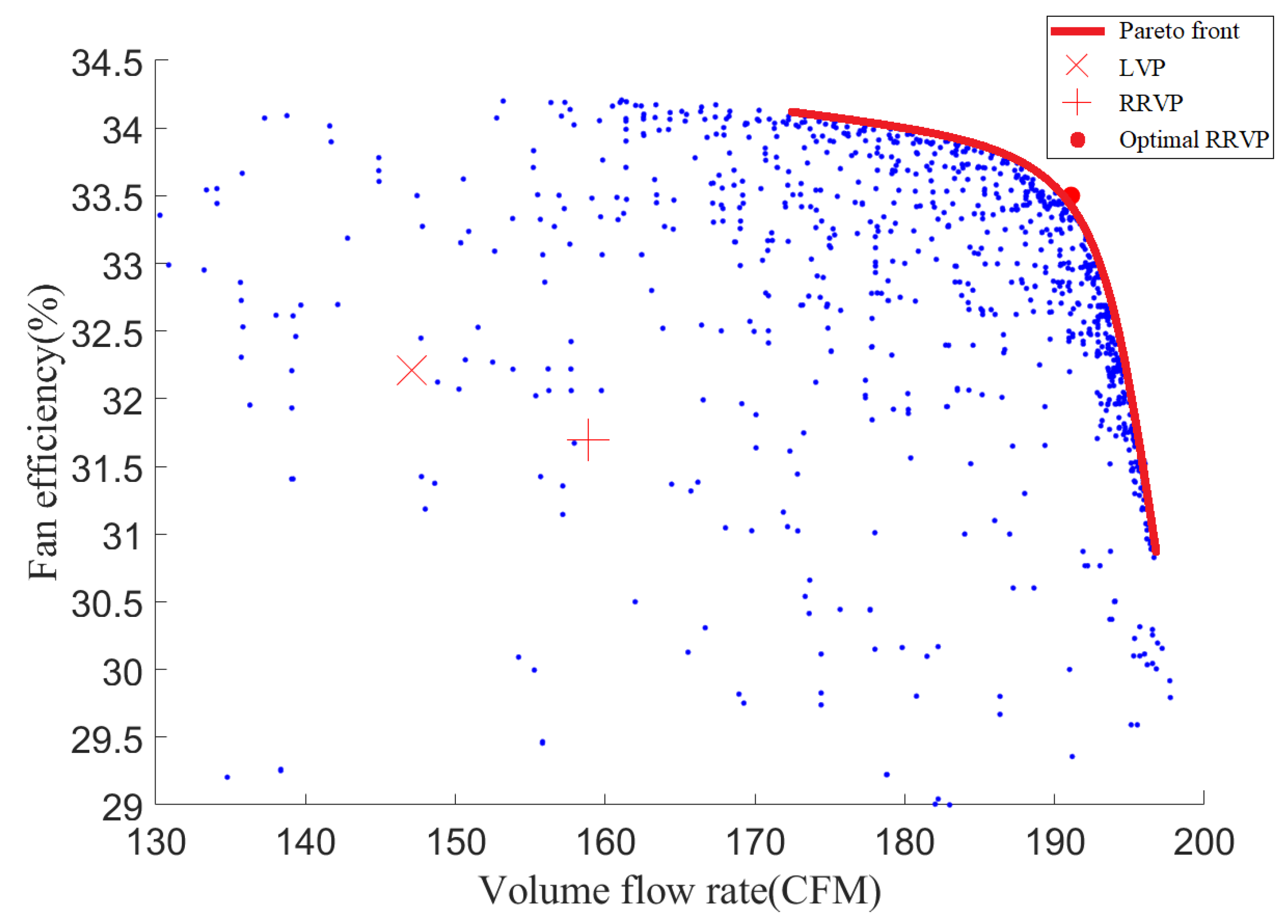
After about one thousand CFD simulations, the multiobjective optimization algorithm with the help of surrogate models finally reached the convergent results. The Pareto front and distribution of all results in the optimization process are shown in Figure 18. The distribution of the results shows that it is difficult for the compact squirrel cage fans to achieve both a high efficiency and a high flow rate. In Figure 18, the point “x” represents the volumetric flow rate and efficiency of the prototype fan with an LVP volute, and the point “+” symbolizes the aerodynamic performance of the fan with the initial RRVP volute. It can be seen that most of the fans with an RRVP volute outperformed the prototype fan. Furthermore, the RRVP volute shows a more significant improvement in flow rate than its capability in increasing the efficiency. Among fans in the Pareto front, we selected one from the optimal fans (the red dot in Figure 18) as a compromise solution between the maximum volumetric flow rate and efficiency of the fan.
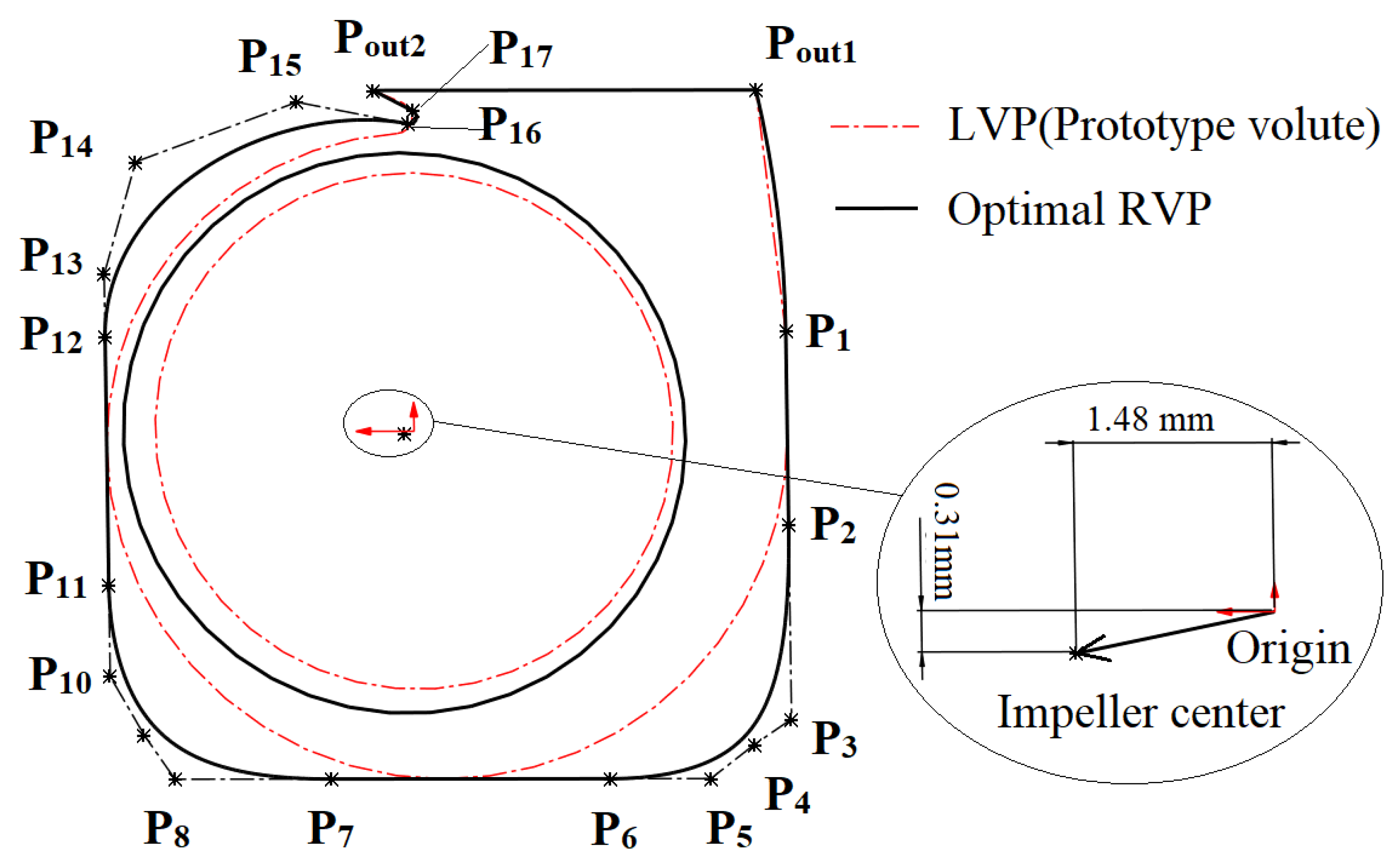
A comparison between the shapes of the final optimal fan and the prototype fan is shown in Figure 19. The slightly moved center of the eccentrically mounted impeller of the optimal fan is shown in the zoomed-in figure. The movement of the optimal impeller to the left side of the RRVP reduces the left gap between the impeller and the volute. It is speculated that this is because the first quarter of the volute has less contribution to the flow capacity for such a compact SCF. Additionally, the volute cross-section along most portions of the RRVP is larger than that of the prototype. Table 5 lists the coordinates of each control point of the optimal volute profile. 
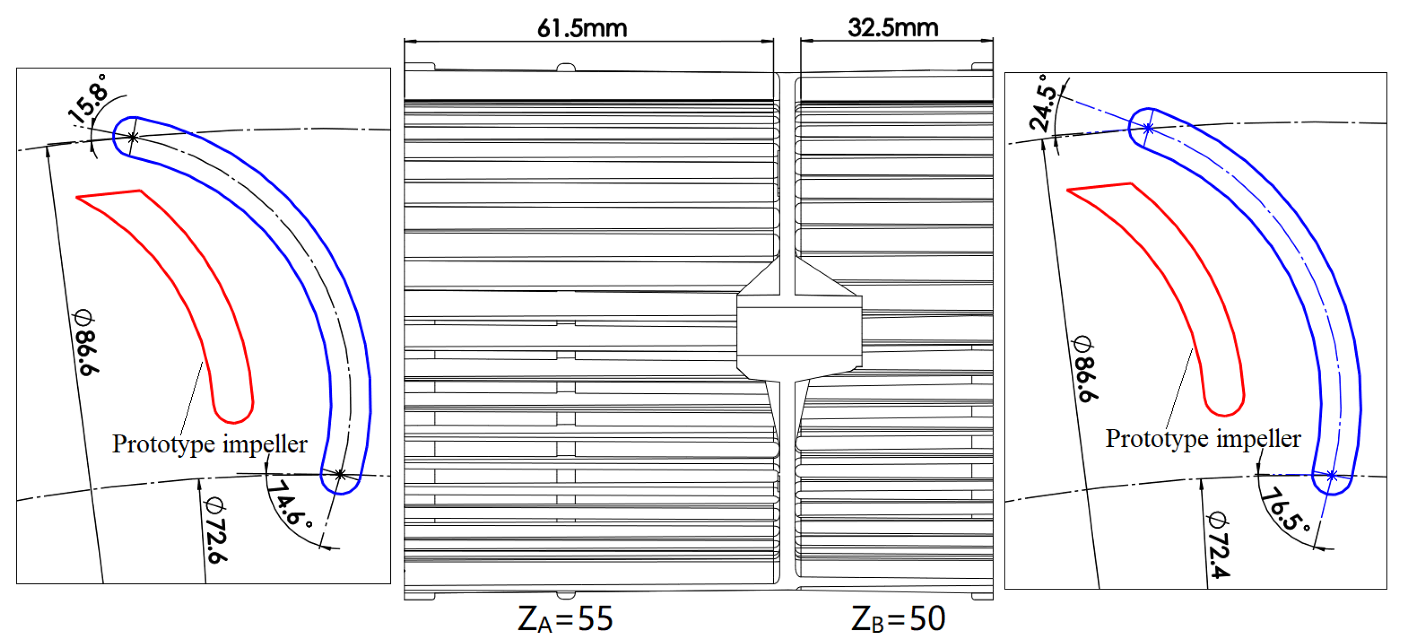
Figure 20 shows the comparison of the blade shapes of the prototype and the optimal fan. Apparently, the optimal fan has an increased blade length and an enlarged volute area. Other optimal results that need noticing are that the blade angles and numbers on the two sides of the middle plane are different for the optimal impeller.
In Table 6, we compare the aerodynamic performance of the fans with the LVP (prototype fan), the original RRVP, and the optimal RRVP volute under the maximum flow rate working condition. Compared with the prototype, the optimal fan’s flow rate was increased by 30% and its efficiency by 1.29%.
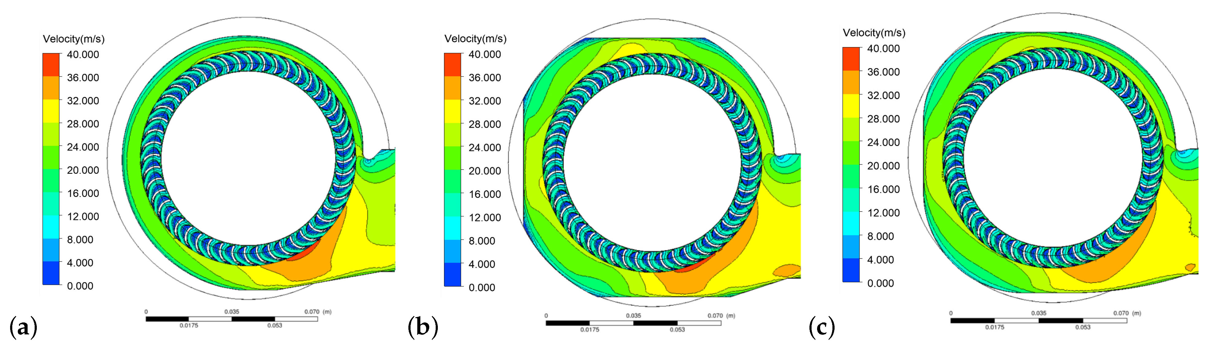
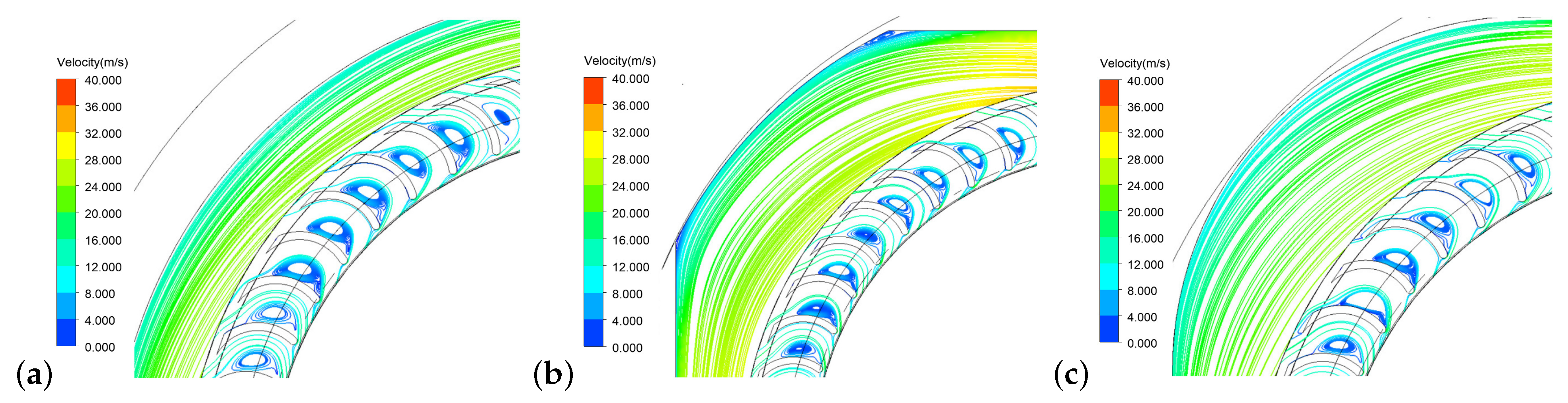
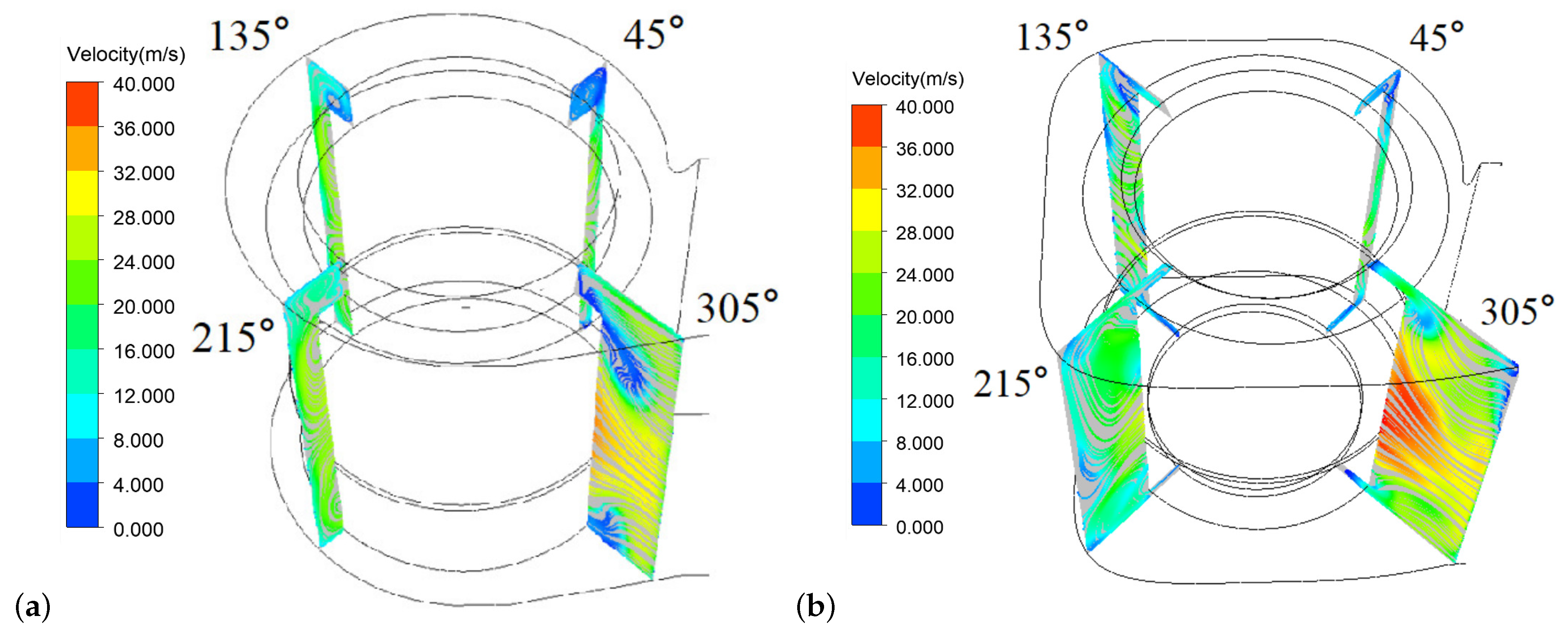
To explore the aerodynamic mechanism for the improvement in aerodynamic performance, the flow details in the volute of SCFs with the LVP and the optimal RRVP volute were investigated. Figure 21 shows the streamline of the inner flow field at the four corners of the RRVP and the LVP volutes. Clearly, the radial velocity at the exit of the impeller in the optimal RRVP volute is much higher than that in the LVP volute. Additionally, the RRVP volute has relatively larger cross-flow-section than the prototype volute, so that the optimal fan has a greatly improved flow rate. As shown in the 305 degrees section of the volute, the LVP volute has a large recirculation region near the casing. The presence of the recirculation region blocks the air flow in the volute, making it difficult to increase the flow rate. In the optimal RRVP, the recirculation region near to the 305 degrees section was greatly reduced. These factors explain the aerodynamic mechanism for increasing flow rate of the RRVP.
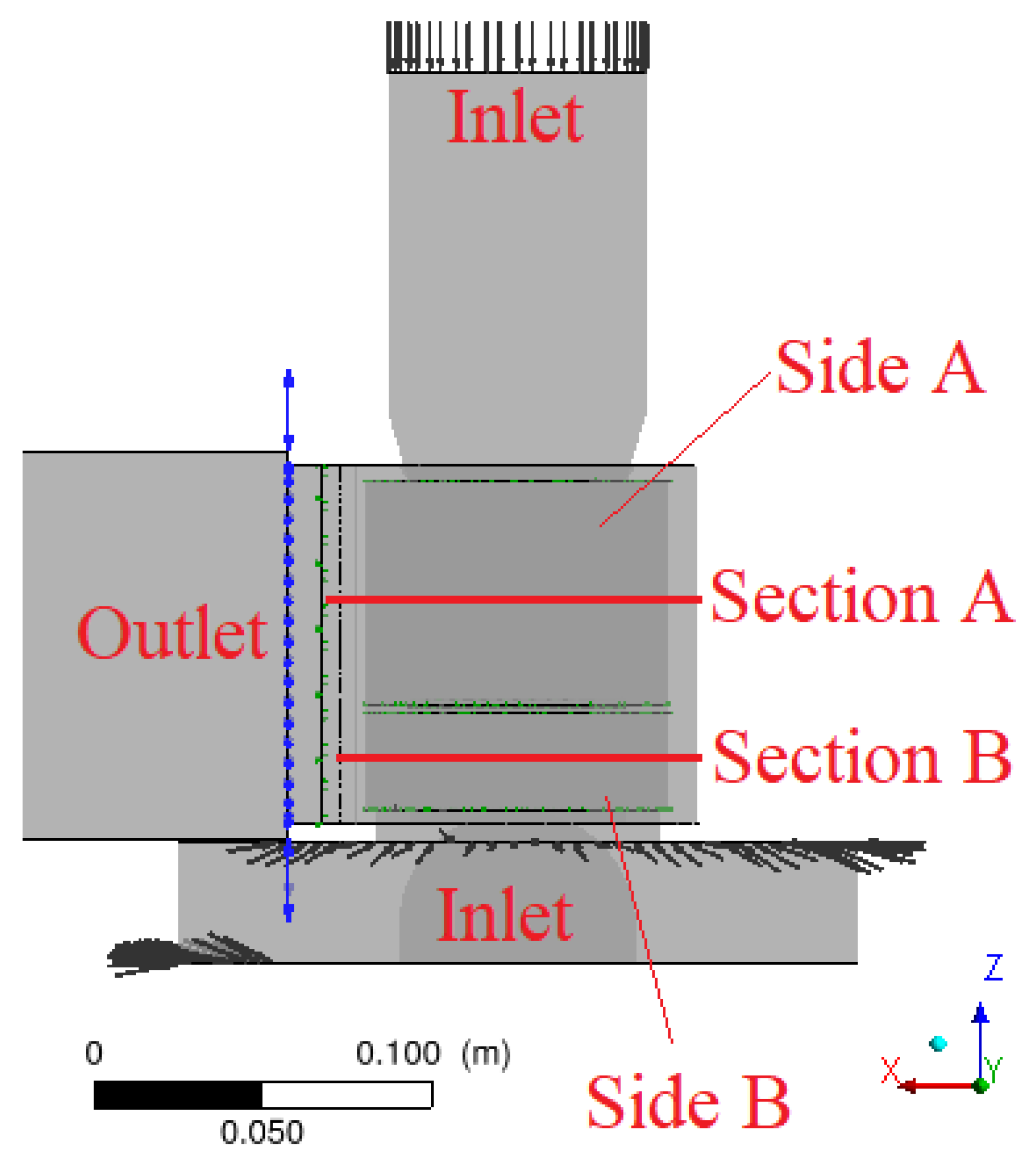
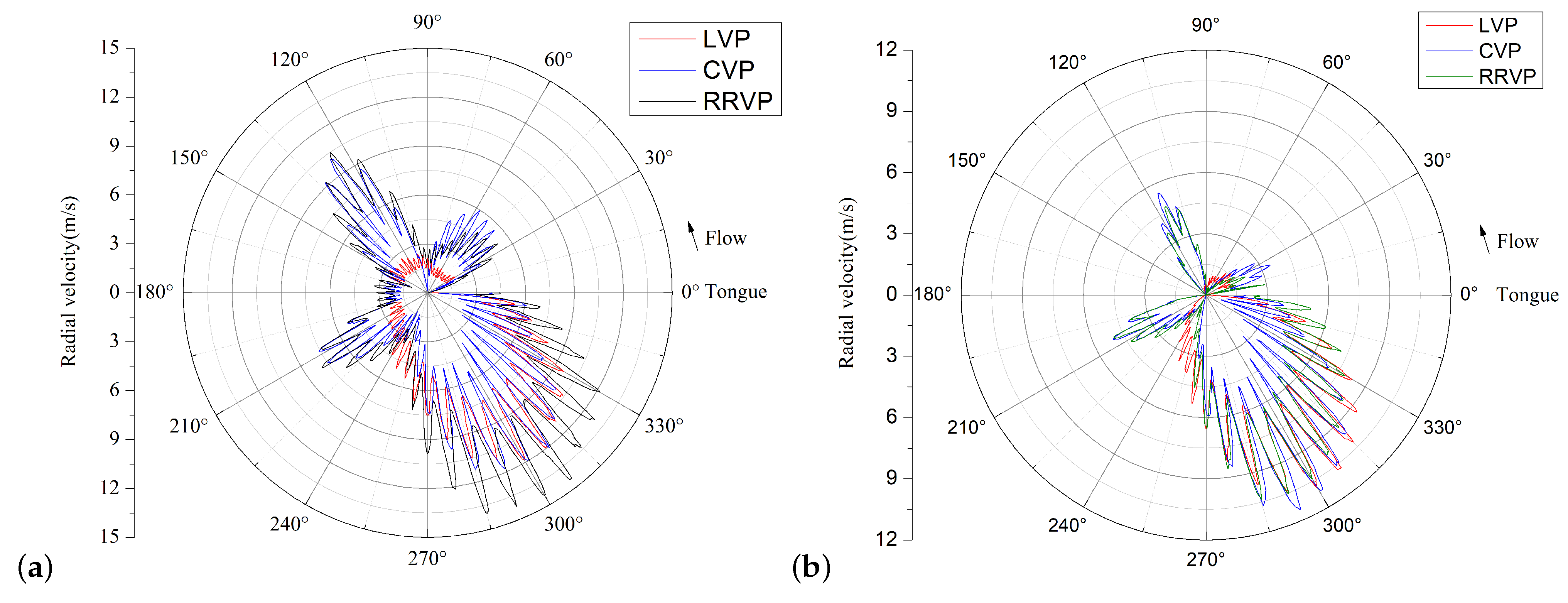
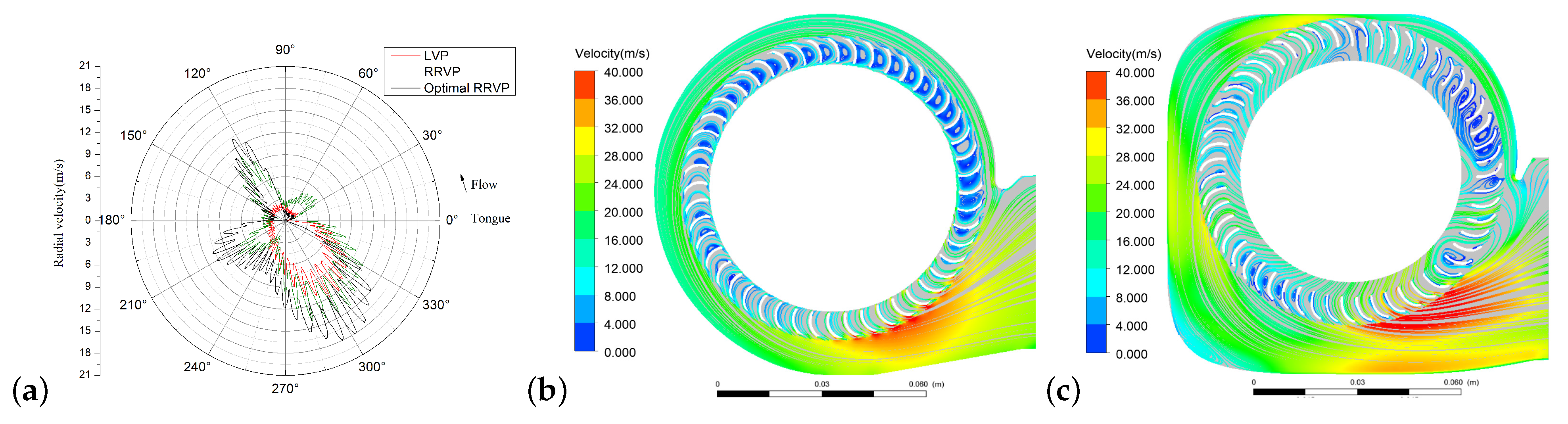
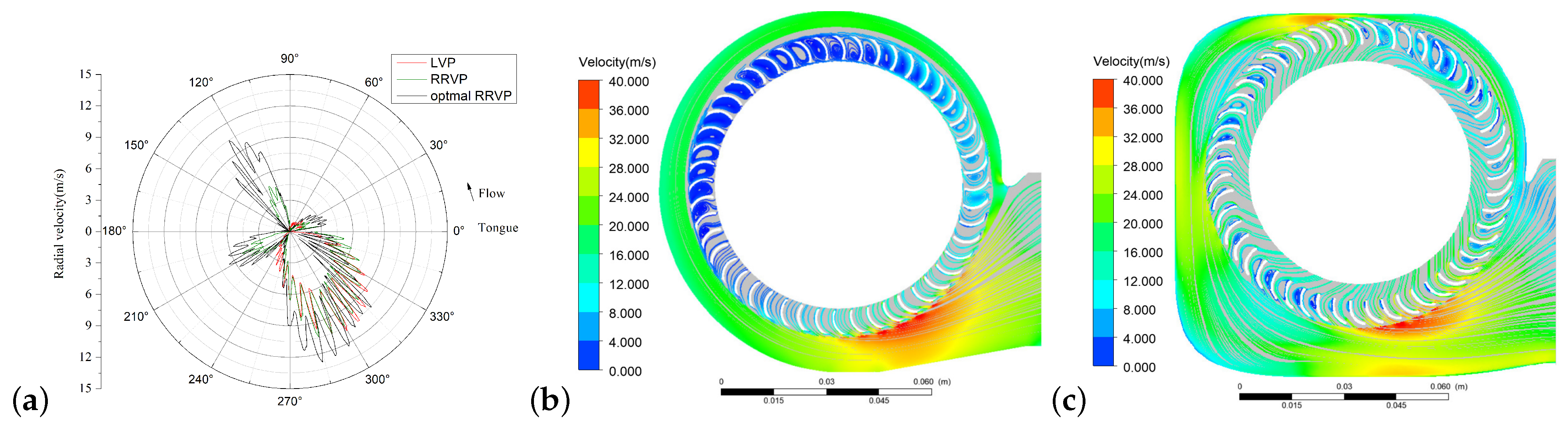
Figure 22a and Figure 23a show the comparison of the impeller outlet radial velocity distribution from 0 to 360 degrees of the volute on section A and section B, respectively. This shows that the radial velocity of the RRVP impeller after 90 degrees is evidently greater than that of the prototype impeller. In addition, the radial velocity of the optimal RRVP volute was improved at all angles, especially in the corner parts of the volute profile. Figure 22b,c and Figure 23b,c show the comparisons of streamlines between the LVP and optimal RRVP volute on sections A and B, respectively. It can be seen that the separation flow in the impeller is greatly improved, and the flow inside the volute is rather smooth. The eccentrically mounted impeller makes a large cross-section near the outlet of the volute.

6. Conclusions

In this study, a new RRVP to increase the volumetric flow rate with a little gain in aerodynamic efficiency for an SCF with a strict space constraint were investigated and optimized. In comparison with common LVP and CVP volute, the proposed RRVP volute shows a superior aerodynamic performance, especially in terms of volumetric flow rate. Some conclusions can be drawn, as follows:
  • The proposed RRVP volute can effectively improve the flow rate of SCFs under strict space restriction. In this case, the maximum flow rate of the SCF with the optimal RRVP was increased by 30% and the total pressure efficiency by 1.29%, compared with the fan with a well-designed LVP volute.
  • The corresponding parameterization method for the RRVP volute was proposed with only 16 control points. With the combination of optimization of the impeller blade profile and the position of the impeller center, the optimization of the compact SCF, which is often encountered in engineering practice, can be conducted with only 23 control variables.
  • By using the MOEA/D-EGO method, the stable Pareto front of the multiobjective optimal design of this SCF with 23 control variables can be achieved within about one thousand CFD simulations. This evident reduction of the expensive CFD computations proves the effectiveness of the present optimal algorithm.
  • The improvement of the flow rate and efficiency for such a compact SCF are mainly improved by two factors: the primary factor is that the rounded rectangle profile has the benefits of both large cross-flow-section and the relative low flow loss, which are helpful to increase the flow rate and efficiency. The second factor is that the optimal fan has an eccentrically mounted impeller, which is beneficial for the increase in the cross-section in the last quarter of the volute and, therefore, for the rise in flow capacity.

Author Contributions

Conceptualization, J.X. and J.L.; methodology, J.X.; software, J.X.; validation, J.X. and J.T.; formal analysis, J.X.; investigation, J.X., J.T., and P.G.; resources, J.X., P.G., and J.L.; data curation, J.X.; writing—original draft preparation, J.X.; writing—review and editing, J.X., J.T., P.G., and J.L.; visualization, J.X. and J.T.; supervision, P.G. and J.L.; project administration, J.L.; funding acquisition, J.L. All authors have read and agreed to the published version of the manuscript.

Funding

This work was financially supported by National Science and Technology Major Project (2017-II-0007-0021).

Acknowledgments

The authors acknowledge the support of National Science and Technology Major Project (2017-II-0007-0021), and all the other scholars for their advice in the process of improving this article.

Conflicts of Interest

The authors declare no conflict of interest. The funders had no role in the design of the study; in the collection, analyses, or interpretation of data; in the writing of the manuscript; or in the decision to publish the results.

Nomenclature

Ddiameter (mm)
Rradius (mm)
Qfan flow rate (CFM)
Pfan pressure rise (Pa)
Wmotor power consumption (W)
Zblade number
α volute scroll spread angle ( )
β blade angle ( )
η fan efficiency (%)
φ volute scroll angle ( )
Φ fan flow coefficient

References

  1. Maneewan, S.; Tipsaenprom, W.; Lertsatitthanakorn, C. Thermal Comfort Study of a Compact Thermoelectric Air Conditioner. J. Electron. Mater. 2010, 39, 1659–1664. [Google Scholar] [CrossRef]
  2. Montazerin, N.; Damangir, A.; Mirian, S. A new concept for squirrel-cage fan inlet. Proc. Inst. Mech. Eng. Part A J. Power Energy 1998, 212, 343–349. [Google Scholar] [CrossRef]
  3. Montazerin, N.; Damangir, A.; Mirzaie, H. Inlet induced flow in squirrel-cage fans. Proc. Inst. Mech. Eng. Part A J. Power Energy 2000, 214, 243–253. [Google Scholar] [CrossRef]
  4. Montazerin, N.; Damangir, A.; Fard, A.K. A study of slip factor and velocity components at the rotor exit of forward-curved squirrel cage fans, using laser Doppler anemometry. Proc. Inst. Mech. Eng. Part A J. Power Energy 2001, 215, 453–463. [Google Scholar] [CrossRef]
  5. Wang, K.; Ju, Y.; Zhang, C. A Quantitative Evaluation Method for Impeller-Volute Tongue Interaction and Application to Squirrel Cage Fan with Bionic Volute Tongue. J. Fluids Eng. Trans. ASME 2019, 141, 081104. [Google Scholar] [CrossRef]
  6. Gholamian, M.; Rao, G.K.; Bhramara, P. Numerical investigation on effect of inlet nozzle size on efficiency and flow pattern in squirrel cage fans. Proc. Inst. Mech. Eng. Part A J. Power Energy 2013, 227, 896–907. [Google Scholar] [CrossRef]
  7. Liu, H.; Jiang, B.; Wang, J.; Yang, X.; Xiao, Q. Numerical and experimental investigations on non-axisymmetric D-type inlet nozzle for a squirrel-cage fan. Eng. Appl. Comput. Fluid Mech. 2021, 15, 363–376. [Google Scholar] [CrossRef]
  8. Li, Z.; Dou, H.S.; Lin, P.; Wei, Y.; Chen, Y.; Lin, L.; Ye, X. Design for a squirrel cage fan with double arc blade. J. Appl. Fluid Mech. 2020, 13, 881–891. [Google Scholar] [CrossRef]
  9. Wang, K.; Ju, Y.; Zhang, C. Effects of curvature radius of volute profile on aerodynamic performance of squirrel cage fan. In Proceedings of the ASME-JSME-KSME 2019 8th Joint Fluids Engineering Conference, AJKFluids 2019, San Francisco, CA, USA, 28 July–1 August 2019; Volume 3;B-2019, pp. 1–9. [Google Scholar] [CrossRef]
  10. Wen, X.; Qi, D.; Mao, Y.; Yang, X. Experimental and numerical study on the inlet nozzle of a small squirrel-cage fan. Proc. Inst. Mech. Eng. Part A J. Power Energy 2013, 227, 450–463. [Google Scholar] [CrossRef]
  11. Nikkhoo, M.; Montazerin, N.; Damangir, A.; Samian, R.S. An experimental study of leaning blades on the half-cone rotor of a squirrel cage fan. Proc. Inst. Mech. Eng. Part A J. Power Energy 2009, 223, 973–980. [Google Scholar] [CrossRef]
  12. Wang, K.; Ju, Y.; Zhang, C. Experimental and numerical investigations on effect of blade trimming on aerodynamic performance of squirrel cage fan. Int. J. Mech. Sci. 2020, 177, 105579. [Google Scholar] [CrossRef]
  13. Kim, K.Y.; Seo, S.J. Shape optimization of forward-curved-blade centrifugal fan with Navier-Stokes analysis. J. Fluids Eng. Trans. ASME 2004, 126, 735–742. [Google Scholar] [CrossRef]
  14. Han, S.Y.; Maeng, J.S. Shape optimization of cut-off in a multi-blade fan/scroll system using neural network. Int. J. Heat Mass Transf. 2003, 46, 2833–2839. [Google Scholar] [CrossRef]
  15. Yang, X.; Jiang, B.; Wang, J.; Huang, Y.; Yang, W.; Yuan, K.; Shi, X. Multi-objective optimization of dual-arc blades in a squirrel-cage fan using modified non-dominated sorting genetic algorithm. Proc. Inst. Mech. Eng. Part A J. Power Energy 2020, 234, 1053–1068. [Google Scholar] [CrossRef]
  16. Zhou, S.; Yang, K.; Zhang, W.; Zhang, K.; Wang, C.; Jin, W. Optimization of multi-blade centrifugal fan blade design for ventilation and air-conditioning system based on disturbance cst function. Appl. Sci. 2021, 11, 7784. [Google Scholar] [CrossRef]
  17. Xiao, Q.; Shi, X.; Wu, L.; Wang, J.; Ding, Y.; Jiang, B. Squirrel-cage fan system optimization and flow field prediction using parallel filling criterion and surrogate model. Processes 2021, 9, 620. [Google Scholar] [CrossRef]
  18. Xiao, Q.; Wang, J.; Jiang, B.; Yang, W.; Yang, X. Multi-objective optimization of squirrel cage fan for range hood based on Kriging model. Proc. Inst. Mech. Eng. Part C J. Mech. Eng. Sci. 2022, 236, 219–232. [Google Scholar] [CrossRef]
  19. Benchikh Le Hocine, A.E.; Poncet, S.; Fellouah, H. CFD modeling and optimization by metamodels of a squirrel cage fan using OpenFoam and Dakota: Ventilation applications. Build. Environ. 2021, 205, 108145. [Google Scholar] [CrossRef]
  20. Zhang, Q.; Liu, W.; Tsang, E.; Virginas, B. Expensive multiobjective optimization by MOEA/D with gaussian process model. IEEE Trans. Evol. Comput. 2010, 14, 456–474. [Google Scholar] [CrossRef]
  21. Chugh, T.; Jin, Y.; Miettinen, K.; Hakanen, J.; Sindhya, K. A Surrogate-Assisted Reference Vector Guided Evolutionary Algorithm for Computationally Expensive Many-Objective Optimization. IEEE Trans. Evol. Comput. 2018, 22, 129–142. [Google Scholar] [CrossRef]
  22. Wen, X.; Mao, Y.; Yang, X.; Qi, D. Design Method for the Volute Profile of a Squirrel Cage Fan with Space Limitation. J. Turbomach. 2016, 138, 081001. [Google Scholar] [CrossRef]
  23. Jiang, B.; Liu, H.; Li, B.; Wang, J. Effects of cut volute profile on squirrel cage fan performance and flow field. Adv. Mech. Eng. 2018, 10, 168781401876691. [Google Scholar] [CrossRef]
  24. Xiao, Q.; Jang, B.; Wang, J. Volute profile design of the squirrel cage fan based on a B-spline curve under space limitation. Proc. Inst. Mech. Eng. Part A J. Power Energy 2020, 234, 889–899. [Google Scholar] [CrossRef]
  25. Menter, F.R. Two-equation eddy-viscosity turbulence models for engineering applications. AIAA J. 1994, 32, 1598–1605. [Google Scholar] [CrossRef]
  26. Bardina, J.E.; Huang, P.G.; Coakley, T.J. Turbulence Modeling Validation, Testing, and Development; Technical Report; NASA Technical Reports Server: Washington, DC, USA, 1997.
  27. Kitadume, M.; Kawahashi, M.; Hirahara, H.; Uchida, T.; Yanagawa, H. Experimental Analysis of 3D Flow in Scroll Casing of Multi-Blade Fan for Air-Conditioner. J. Fluid Sci. Technol. 2007, 2, 302–310. [Google Scholar] [CrossRef]
  28. Jin, Y.; Wang, H.; Sun, C. Data-Driven Evolutionary Optimization; Springer: Berlin/Heidelberg, Germany, 2021; pp. 9–11. [Google Scholar]
  29. Zhang, Q.; Li, H. MOEA/D: A multiobjective evolutionary algorithm based on decomposition. IEEE Trans. Evol. Comput. 2007, 11, 712–731. [Google Scholar] [CrossRef]
  30. Yang, M.; Gan, Y.; Gao, L.; Zhu, X. A structural optimization model of a biochemical detection micromixer based on RSM and MOEA/D. Chem. Eng. Process.-Process Intensif. 2022, 173, 108832. [Google Scholar] [CrossRef]
  31. Zhang, Y.; Hu, S.; Wu, J.; Zhang, Y.; Chen, L. Multi-objective optimization of double suction centrifugal pump using Kriging metamodels. Adv. Eng. Softw. 2014, 74, 16–26. [Google Scholar] [CrossRef]
  32. Zhang, Y.; Wu, J.; Zhang, Y.; Chen, L. Design optimization of centrifugal pump using radial basis function metamodels. Adv. Mech. Eng. 2014, 6, 457542. [Google Scholar] [CrossRef]
  33. Lophaven, S.N.; Nielsen, H.B.; Sondergaard, J. DACE: A Matlab Kriging Toolbox; The Technical University of Denmark: Lyngby, Denmark, 2002; Volume 2. [Google Scholar]
  34. Tian, Y.; Cheng, R.; Zhang, X.; Jin, Y. PlatEMO: A MATLAB Platform for Evolutionary Multi-Objective Optimization [Educational Forum]. IEEE Comput. Intell. Mag. 2017, 12, 73–87. [Google Scholar] [CrossRef] [Green Version]
Figure 1. Volute design method under size limitation.
Machines 11 00283 g001
Figure 2. Internal structure and flow path in the OTR microwave.
Machines 11 00283 g002
Figure 3. The prototype squirrel cage fan used in performance testing.
Machines 11 00283 g003
Figure 4. Internal configuration of the squirrel cage fan.
Machines 11 00283 g004
Figure 5. Dimensions of the size limitation of the squirrel cage fan.
Machines 11 00283 g005
Figure 6. Schematic diagram of fan flow domain.
Machines 11 00283 g006
Figure 7. Schematic diagram of each component’s mesh: (a) entry part on the motor side, (b) nozzle intake, (c) impeller, (d) extension passage of volute outlet, (e) volute.
Machines 11 00283 g007
Figure 8. Grid independence verification.
Machines 11 00283 g008
Figure 9. Shape comparison of different volute profiles’ design.
Machines 11 00283 g009
Figure 10. Velocity contour in section A for different volutes: (a) LVP, (b) CVP, (c) RRVP.
Machines 11 00283 g010
Figure 11. Streamline flow in the corner for different volutes: (a) LVP, (b) CVP, (c) RRVP.
Machines 11 00283 g011
Figure 12. Comparison of impeller outlet radial velocity distribution: (a) section A, (b) section B.
Machines 11 00283 g012
Figure 13. Parametric diagram of the RRVP volute.
Machines 11 00283 g013
Figure 14. Quartic Bezier curve and its control points.
Machines 11 00283 g014
Figure 15. Geometric parameters of each impeller in optimization: (a) axial length, (b) blade profile.
Machines 11 00283 g015
Figure 16. Schematic diagram of the Pareto optimality.
Machines 11 00283 g016
Figure 17. Comprehensive flow chart of the fan optimization framework.
Machines 11 00283 g017
Figure 18. Pareto front and distribution of all results in optimization process.
Machines 11 00283 g018
Figure 19. Prototype and optimal volute profile with its control points.
Machines 11 00283 g019
Figure 20. Comparison of prototype and optimal fan’s impeller blade profile.
Machines 11 00283 g020
Figure 21. Comparison of impeller outlet radial velocity distribution and streamlines in section A: (a) LVP, (b) optimal RRVP.
Machines 11 00283 g021
Figure 22. Comparison of impeller outlet radial velocity distribution and streamlines in section A: (a) radial velocity distribution, (b) LVP, (c) optimal RRVP.
Machines 11 00283 g022
Figure 23. Comparison of impeller outlet radial velocity distribution and streamlines in section B: (a) radial velocity distribution, (b) LVP, (c) optimal RRVP.
Machines 11 00283 g023
Table 1. Aerodynamic performance parameters of a single prototype fan at MVP.
Fan ParameterUnitValue
Exp. volumetric flow rateCFM144
Rotation speedrpm3350
Inlet total pressureatm1
Outlet static pressureatm1
Exp. total pressure risePa195
Table 2. Grid distribution.
Region NameGrid TypeGrid Number
Moter side intake (right)Hexahedral467,630
Nozzle intake (left)Hexahedral779,343
Right impellerHexahedral1,537,114
Left impellerHexahedral2,967,981
VoluteTetrahedral3,778,634
OuttakeHexahedral491,124
Entire modelMixing10,021,826
Table 3. Comparison of test and calculation results of prototype fan under maximum flow working condition.
ParameterSymbol/UnitExp.CFDError
Volumetric flow rate Q v / CFM144147.12.1%
Pressure rise Δ P t / Pa195198.31.6%
Efficiency η / %31.532.212.2%
Table 4. Comparison of the fan aerodynamic performance of different volutes under maximum flow working condition.
Parameter Q v / CFM Δ P / Pa η / %
LVP147.1198.332.21
CVP155.4185.730.32
RRVP158.9196.431.69
Table 5. Coordinates of each control point in the optimal volute profile.
Control Pointsx/mmy/mm
P o u t 1 52.2000−53.0000
P 1 15.2813−57.0000
P 2 −14.3687−57.0000
P 3 −44.1901−57.0000
P 4 −48.1187−51.2310
P 5 −53.3000−44.5266
P 6 −53.3000−29.2812
P 7 −53.300013.3875
P 8 −53.300037.3364
P 9 −46.553841.9266
P 10 −37.542447.0000
P 11 −23.568747.0000
P 12 14.575047.0000
P 13 24.075347.0000
P 14 41.301741.9375
P 15 50.417517.1605
P 16 47.07950.1856
P 17 49.0703−0.5121
P o u t 2 52.20005.5000
Table 6. Comparison of the results.
Parameter Q v Δ P t η
UnitCFMPa%
LVP147.1198.332.21
RRVP158.9196.431.7
Optimal RRVP191.1191.733.5
Disclaimer/Publisher’s Note: The statements, opinions and data contained in all publications are solely those of the individual author(s) and contributor(s) and not of MDPI and/or the editor(s). MDPI and/or the editor(s) disclaim responsibility for any injury to people or property resulting from any ideas, methods, instructions or products referred to in the content.

