1. Introduction
Multiple robot manipulators that carry out independent tasks in a shared workspace need a solution to avoid mutual collisions. The risk of collision is an issue in various robotic fields, including industrial and service applications. However, robotic system software, which requires the evaluation of such issues, is traditionally developed by robotic system experts. Moreover, manual tests are carried out both in the real system and in the simulation environment. Therefore, the verification and validation (V&V) of the system software depend entirely on the experience and attention of the experts. If the V&V of the system software is not conducted adequately, overlooked system errors can lead to downtime for extremely expensive production plants.
Although software plays an ever-increasing role in robotics, current software engineering practices are perceived as insufficient, often leading to error-prone software that is hard to maintain and cannot easily evolve [
1]. Moreover, research and industry have tried to propose many model-driven solutions to engineer the software of robotics systems. Casalaro et al. [
2] provide a map of software engineering research in MDE for robotic systems since there is no systematic study of state-of-the-art developments in model-driven engineering (MDE) for robotic systems. Robotic systems are advanced cyber-physical systems (CPS) composed of an intricate blend of hardware, software, and environmental components. Software engineering can be very beneficial in the CPS domain; however, it has traditionally been considered an auxiliary concern of robotic system construction. On the other hand, software engineering technologies and methodologies can facilitate the development of robotic systems by adopting a systematic, disciplined, quantifiable approach in each phase of a software application’s lifespan, from requirements analysis, system architecture definition, and component design to code implementation, testing, and deployment [
3]. Some studies provide roboticists with methods and tools to easily create and validate software for robotic systems. Miyazawa et al. [
4] and Ye et al. [
5] propose a set of constructs suitable for modeling robotic applications and supporting verification via model checking and theorem proving. Their goal is to support roboticists in writing models and applying modern verification techniques using a language familiar to them. With the use of formal verification methods together with software engineering approaches, robotic systems can be less error-prone and more reliable, and the dependency on human skills can be eliminated.
Although formal verification methods have been discussed in the software domain for many years, they are relatively new for robotic systems. Therefore, the demonstration of workflows and application models for formal verification of robotic systems is essential for dissemination. Some survey papers are investigating formal verification methods for robotic systems. Sinha et al. [
6] survey formal methods for the dependability of industrial automation systems. They focus on offline or static approaches, leaving out online or runtime approaches like monitoring, diagnosis, and fault tolerance. Luckcuck et al. [
7] systematically survey the state of the art in formal specification and verification for autonomous robotics. The main emphasis is that the commonly used both testing methods and simulations are insufficient to ensure correctness, and there is a need to employ formal methods for autonomous robotic systems. Zheng et al. [
8] present a literature survey, an online survey of CPS researchers, and interviews in their paper, Perceptions on the State of the Art in Verification and Validation in Cyber-Physical Systems. Ingrand [
9] deals with recent trends in the formal V&V of autonomous robot software. Autonomous robot software needs to be organized along with a particular architecture. Some architectures make easier the V&V of the overall system.
Some studies present architectures to implement V&V for robotic systems. Kanter and Vain [
10] present a testing toolkit named TestIt. It provides tools for the automated model-based testing of autonomous multi-robot systems. They use UPPAAL (Ver.4.1.26-2) [
11] for modeling and model checking. Wang et al. [
12] present a model-based approach, which has the phases of modeling, verification, and automatic code generation. In their framework, UPPAAL is employed for verification, and the code generator produces ROS code. An industrial robot application of grasping a cup is used to demonstrate and evaluate the proposed framework.
The use of various verification methods like model checking, runtime verification, and simulation-based testing, in combination, increases the verification coverage and provide a more reliable system. Webster et al. [
13] present an approach for the V&V of a robot assistant in the context of human–robot interaction. They use model checking, simulation-based testing, and user validation in experiments. They entitle their systematic approach corroborative V&V. They employ PRISM (Ver.4.7) [
14] for model checking and ROS–Gazebo [
15] for simulation-based testing. Villani et al. [
16] propose the combined application of two verification techniques: model checking with UPPAAL and CoFI (Conformance and fault injection) model-based testing with ConData [
17]. They present the tool and discuss its usage in industrial software development cases. Kejstova et al. [
18] describe a novel approach for adapting an existing software model checker to perform precise runtime verification. They assert that the runtime verification after model checking improves coverage. Desai et al. [
19] also promote a similar approach. They present an approach for validating the end-to-end correctness of a robotic system by combining model checking and runtime verification. They claim that combining model checking with runtime verification provides a bridge between software verification and the actual execution of the software on a real robotic platform in the physical world.
On the other hand, demonstrating formal verification methods in robotic system applications is of great importance. These applications serve as a model for robotic system developers. These demonstrations will remain valuable until formal verification methods become standard processes in robotic systems and tools are developed to facilitate this process. Halder et al. [
20] propose an approach to model and verify ROS systems by using the UPPAAL model checker, focusing on one of the main features of ROS, the communication between nodes. Webster et al. [
21] present a case study on formal verification for a high-level planner for the robot named Care-O-bot, an autonomous personal robot assistant. The robot can implement many service tasks in a structured robot house by operating close to its human operators. In this study, the robot models and their environment are formally verified by using model checking. Konur et al. [
22] develop and apply automated probabilistic formal verification techniques to robot swarms. They used the probabilistic model checker PRISM and analyzed the probabilistic properties of the swarm. They targeted an existing swarm algorithm for foraging robots. Gjondrekaj et al. [
23] present a formal verification approach for collective robotic systems. They used the formal language KLAIM and related analysis tools. They claim that while existing approaches focus on microscopic or macroscopic views of the system, they model aspects of both the robot hardware and behavior, and the related environment. They model a scenario of collective transport by robots. Dixon et al. [
24] use formal verification techniques for analyzing the emergent behaviors of robotic swarms. They apply model checking to check whether temporal properties are satisfied for all the possible behaviors of the system. Weismann et al. [
25] present a compiler that can transform industrial robot programs into PROMELA models. Then, they implement model checking using SPIN (Ver.6.0) to check collisions and deadlocks in a car-body welding station with nine robots. Quottrup et al. [
26] present a study in which they model, analyze, and verify motion-planning problems in a scenario with multiple robotic vehicles. The verification is employed by using the verification software UPPAAL. Gu et al. [
27] explore model checking for the automatic generation of mission plans for autonomous vehicles. They propose modeling autonomous vehicles as agents in timed automata with a monitor. Then, they implement a tool called TAMAA (timed-automata-based planner for multiple autonomous agents). The demonstration is conducted in an industrial autonomous wheel-loader use case. Wang et al. [
28] present a motion planning method using model checking for reconfigurable robot systems. The verification of the model is implemented by UPPAAL.
Industrial robots are programmable multifunction mechanical devices designed to move material, parts, tools, and specialized devices in order to perform a variety of tasks including assembly, sorting, inspection, and others. Many tasks require the robot to work in coordination with other robots and mechanisms like conveyor bands and CNCs. Studies indicate that many robot accidents occur during non-routine operating conditions, such as programming, maintenance, testing, setup, or adjustment. Rather than directly programming and testing a robotic system, modeling the system software, verifying the model with a formal approach, and subsequently programming in accordance with the model will not only reduce accidents but also increase confidence in the safety of the developed system.
This paper presents a methodology from creating verified models to constructing software designs for robotic systems. The methodology is explained through a case study involving multiple industrial robot manipulators with path conflicts. When there is an overlap in the workspaces of more than one robot, they may collide with each other in their movements in this overlapping space. In order to avoid a safety problem, the robots should not have a path passing through the overlapping space or they should be synchronized. While a solution is proposed for the case study consisting of a safety problem that is encountered with many similar problems in production processes, the methodology for the safety verification of robotic systems is also given. The verified models are constructed by using two prominent model-checking tools: UPPAAL and PRISM. The comparison of the two tools is conducted in terms of the suitability and effectiveness of their features for robotic systems. From the verified model, the design of the software in accordance with the model is explained.
This paper uses the formal method, which is model checking, for the safety verification of multiple industrial robot manipulators with path conflicts. The main contributions are: (i) the presentation of model-checking methods for the conflict resolution of multiple industrial robot manipulators that have a shared workspace; (ii) the creation of suitable models in a sample scenario that can be easily adapted to different similar scenarios; and (iii) demonstration of the opportunities offered by the model-checking method for the effective programming of robot systems. The paper is organized as follows. In
Section 2, we introduce the model-checking technique with two different model constructions.
Section 3 describes the case study with modeling.
Section 4 presents the verification analysis. The results and discussions are given in
Section 5. Then, we provide concluding remarks and directions for future work in
Section 6.
2. Model Checking
Model checking is one of the techniques for the formal verification of systems. It verifies the correctness of a system (that is, meeting the defined requirements) by rigorously exploring the behavior of the model, which is an abstraction of the system, expressed in mathematical notation. Thus, all possible behaviors of the systems are described by a finite structure such as a finite-state automaton. Then, the desired properties are specified in a property specification language e.g., temporal logic. Furthermore, all possible paths throughout the automaton correspond to all possible runs of the system. There are many tools for model checking. Two of them, UPPAAL and PRISM, are used in this study. Thus, the first stage of the formal verification of the system using the model-checking technique is to construct the behavioral model of the system. In the following subsections, we introduce the system modeling formalisms utilized by UPPAAL and PRISM, respectively.
2.1. System Modeling Based on Timed Automata
Timed automata were introduced as a formal notation to model the behavior of real-time systems [
29,
30]. This formalism provides labeled state-transition graphs with timing constraints using real-valued clock variables. The state transition system
is defined by a tuple
, where
is a set of states,
is a set of initial states,
is a set of labels (or events), and
is a set of transitions. The system starts in an initial state, and any transitions between the states are written by
for
where
and
.
The behaviors of the system may also be expressed as a state transition system with timing constraints. , also called a timed automaton, is defined by a tuple . is a finite set of locations (representing states of ), is the set of start (initial) locations, is the finite set of clocks, is a set of actions (actions, co-actions, internal -action), and is a set of edges (transitions) between locations with an action, a guard, and a set of clocks. is the set of clock constraints involving clocks from , and is the powerset of . A clock constraint is simply a term of the form , where is a clock, is a constant, and is a comparison operator. , which is called an invariant, is a mapping that labels each location in with some clock constraint in .
The states of are represented by pairs , where is a location and is a clock interpretation for , such that satisfies the invariant . The set of all states of is denoted by . A state is the initial state if is an initial location of and for all clocks .
The transition may occur with elapse of time for a state and a real-valued time increment , , if for all , satisfies the invariant . It may also occur with a location switch for a state and a switch representing an edge from location to location , where is a label, is a guard and a clock constraint over , and is a subset of clocks to be reset. The location switch implements . means the clock assignment that maps all clocks in to 0 and agrees with for other clocks in .
Timed automata are often composed of a network of timed automata over a common set of clocks and actions, consisting of timed automata , .
The expressions in timed automata can be addressed in guard, invariant, channel, and update. A guard is a particular expression evaluating a Boolean function on edges. An invariant is an expression that indicates the time that can be spent on a node. A channel is considered for synchronizing the progress of two or more automata. An update is an expression set that assigns values to clocks and variables.
2.2. System Modeling Based on Continuous Time Markov Chains (CTMC)
A continuous-time Markov chain (CTMC) is a continuous stochastic process. The process changes state according to an exponential random variable and then moves to a different state as specified by the probabilities of a stochastic matrix. A continuous-time Markov chain
is a tuple
, where
is a finite set of states;
is the transition rate matrix; and
is a labeling with atomic propositions [
31].
assigns to each state
the set
of atomic propositions
that are valid in
.
A transition between and may occur when , and is the probability that the transition can be triggered within time units. Thus, the delay of transition may occur with the exponential distribution with the rate .
2.3. Relation between Verification Models and Software Design
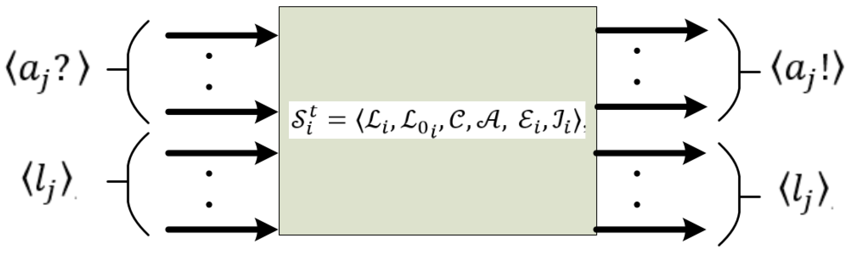
Software designs generally consist of many modules that interact with each other. If an object-oriented approach is used for the software design, each module becomes an instance of a class. The model of each module may be represented by timed automata or CTMS, and the behavior of each module in the overall software is represented by the network of timed automata, as seen in
Figure 1.
In
Figure 1,
are the sent synch messages from the
module to other modules for triggering
action. Similarly,
are the received synch from the
module to the
module for triggering
action. Some state transitions of the
module may depend on the states of other modules as the parameters of the guard condition. Therefore,
are the locations (states) of a module needed by another module.
3. Multiple Industrial Robot Systems Operating in a Shared Workspace: A Case Study
Some robotic production scenarios need multiple robot manipulators to operate close to each other. In this case, the robots in a shared workspace may cause safety issues that will result in a mutual collision. Various approaches can be chosen to avoid a collision. One of them is to employ online or offline motion planning to prevent collisions. Another approach is to synchronize the robots in possible collision zones and make them wait. In all cases, robot software should be developed to ensure safe operation.
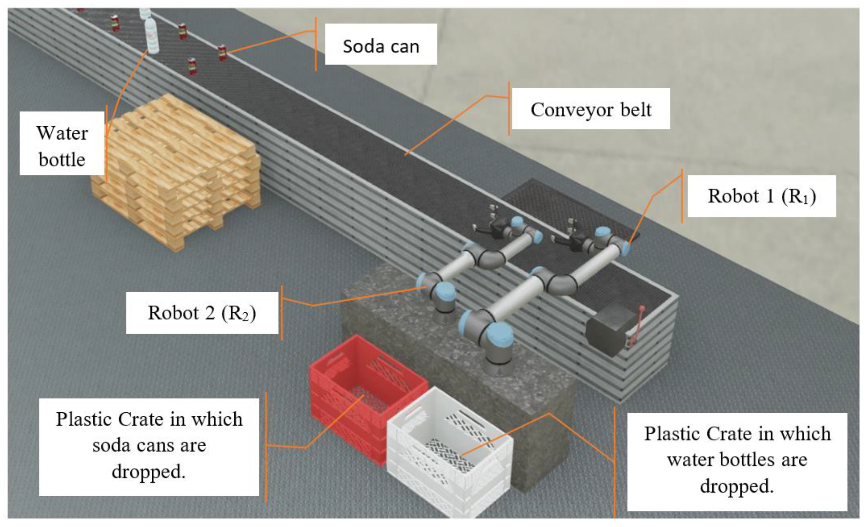
We studied a robotic production system, including two industrial robots sharing a workspace. The scenario discussed includes common problems with many robotic production systems, and the solution can be generalized to be used in all these systems. This system can be seen in
Figure 2.
The aim is to throw the red soda cans on the conveyor belt into the red crate and the white water bottles into the white crate. Two robot arms in the system, called UR10 (R
1) and UR5 (R
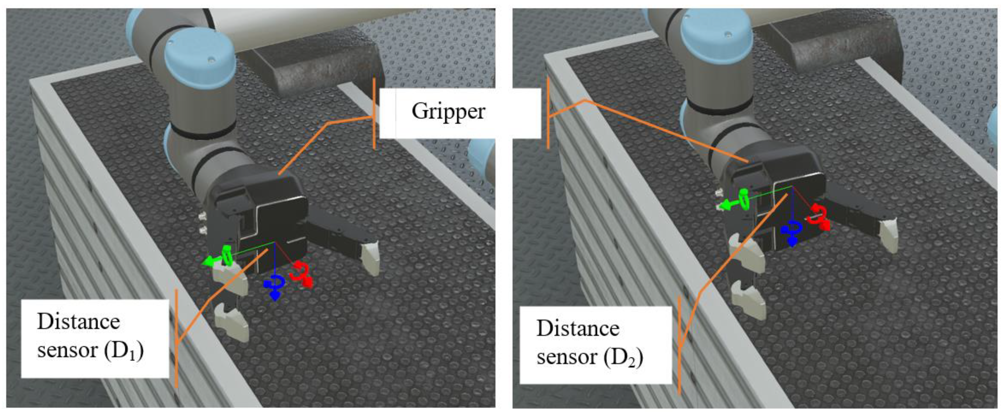
2), implement the task. There is a gripper mechanism at the end of the robot arms. As shown in
Figure 3, there are two distance sensors labeled D
1 and D
2 in the gripper. The water bottle is taller than the soda can. Due to the size of the soda can, it can only be detected with the D
1 sensor. On the other hand, a water bottle can be detected by both D
1 and D
2 sensors. In this case, depending on the distances measured by D
1 and D
2, it can be determined whether the object entering the gripper is soda or water.
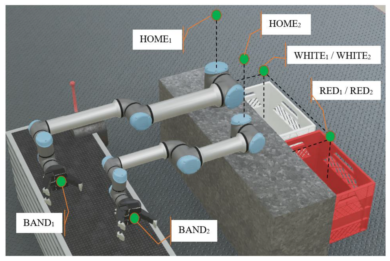
The tips of the robot arms move point-to-point through the pre-determined positions. The pre-determined positions are shown in
Figure 4. Each robot waits for the object on the conveyor band at the position BAND
i. When the object is subsequently perceived and grasped, then the robot moves at the position HOME
i. If the grasped object is a soda can, the robot moves to RED
i and drops the soda can into the red crate. If the grasped object is a water bottle, the robot moves to WHITE
i and drops the water bottle into the white crate. Then, the robot moves back to the position BAND
i over HOME
i.
3.1. Description of the Problem
Let robots perform their task in a shared workspace . The number of robots is . Each task requires the tip, , of to follow a precomputed path passing through some waypoints on . At , has configurations in joints space of and in task space , of . The degree of freedom (DOF) for the robot is . Assume that is moving from any to , where at the same period with , , and , or is moving from any to , where , then the path between and for , and the path between and for , include the path conflict. If these paths are implemented at the same period by and , then it would probably cause a collision when the robots are not synchronized properly. This is a safety problem that needs to be solved. It is necessary to develop a solution for such problems and to verify that the solution provides safety.
For the case study, there are two robots where each follows the path
including
. The scenario requires each robot (i ϵ [
1,
2]) to follow the steps below:
The safety requirements are defined as
- RQ1.
should not move to while is at or moving from/to .
- RQ2.
should move to neither nor while is at or moving from/to .
- RQ3.
should not move to while is at or moving from/to .
- RQ4.
should move to neither nor while is at or moving from/to .
- RQ5.
should not move directly between and for .
Any model for task programming of the robots needs to be verified to confirm whether the safety requirements RQ1–RQ5 are satisfied. In this paper, model checking as a formal verification approach is used. Model checking is employed at the design stage of the program, in which a model of the program is constructed. Since the model is typically non-deterministic, each run of the model can be different from the last. A model checker, which implements the model-checking approach, exhaustively analyzes all possible executions of the model in order to establish some properties, usually derived from the requirements [
21].
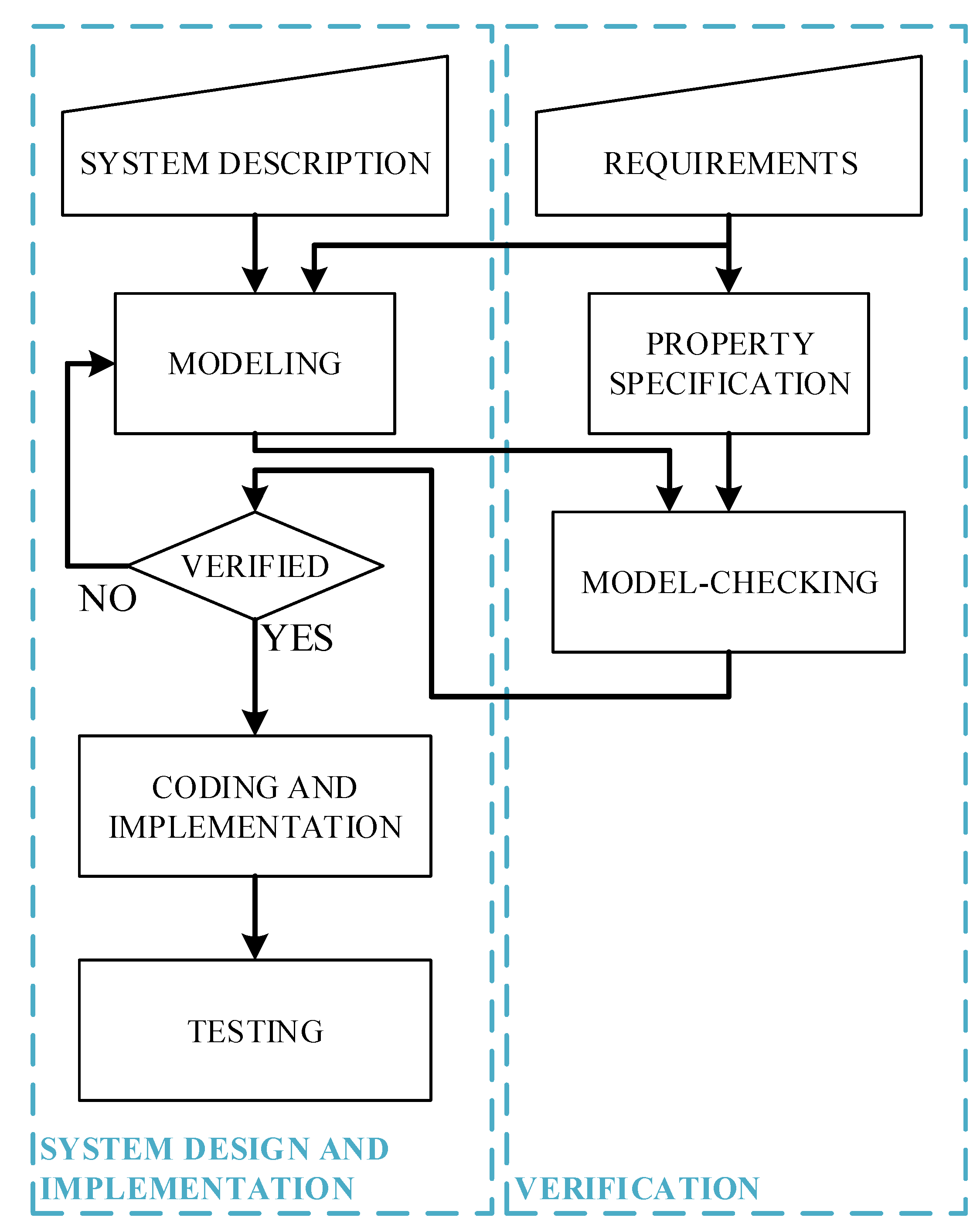
The workflow for verifying the system based on model checking is implemented as shown in
Figure 5. For the model-based development of a system, models are constructed at the design stage by using the description and requirements of the system. The description and requirements of the system are used to create the models. It is necessary to verify that the models meet the requirements. Model checking is employed for verification. Then, the verified models are implemented and tested.
3.2. Timed Automata Modeling
Various V&V tools are specialized in different system behaviors, such as the UPPAAL model checker. It is a commonly used tool for the modeling, simulation, and verification of real-time systems, and was developed by Uppsala University and Aalborg University [
11]. It uses timed automata extended by real-value clocks for system modeling. It also uses TCTL (timed computation tree logic) to express properties to be verified against given specifications.
The robotic system is modeled as a network of timed automata. Each automaton may be constructed parametrically as a template in which the automata may represent the behavioral model of various subsystems. For example, there are two robot manipulators, and a single template models both of them. Four different templates–robot controller, gripper, product detector, and conveyor band–are modeled to represent the case study scenario. Each template is modeled using timed automata. In addition, the templates include a parameter that simultaneously enables the execution of multiple instances on one template.
Modeling begins with the identification of functional modules in the system. Then, the behavioral states of each module are determined. For each module, the actions and states related to other modules are determined. Last, a timed automata model of each module is created.
3.2.1. Robot Controller
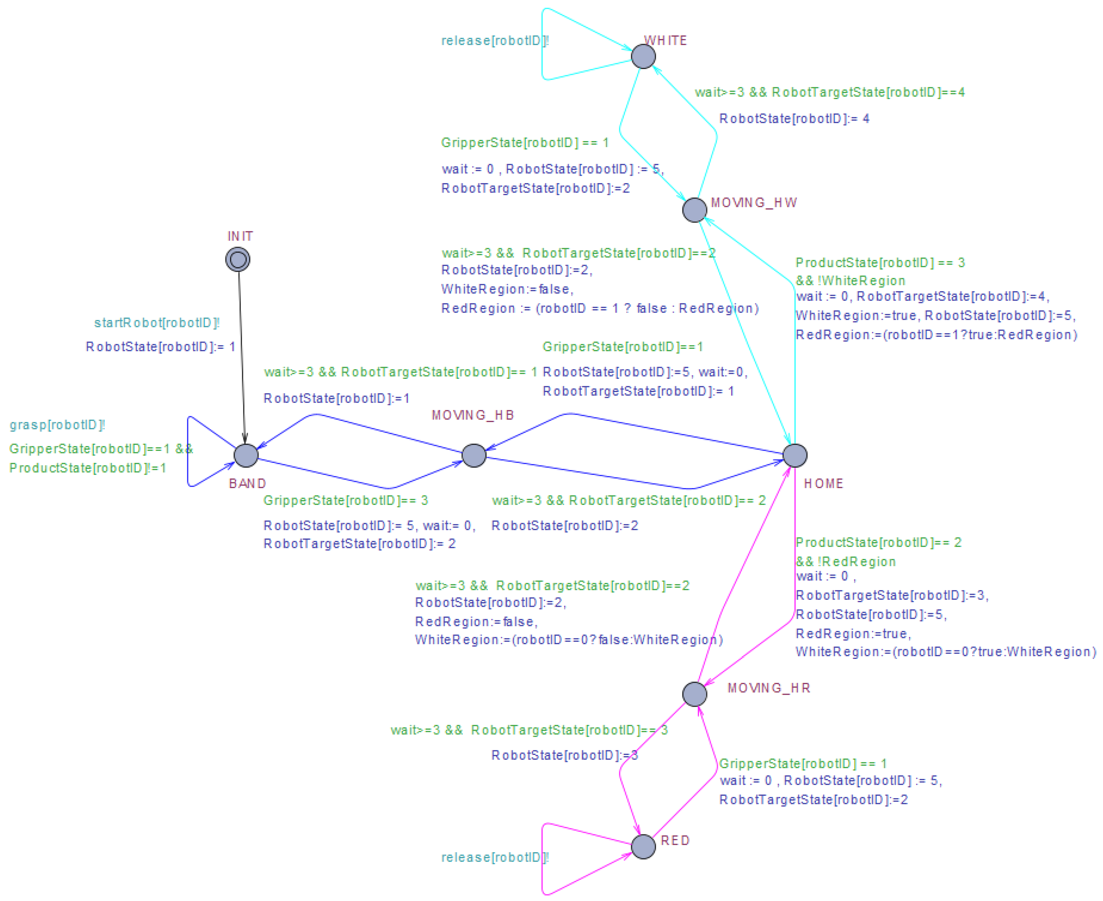
The case study has four waypoints–
,
,
and
–all of which are also considered to be states of the robot. It takes time for the robots to move between the waypoints. Therefore, another state needs to be defined, namely
, which represents the robot moving from/to any primary waypoint, as seen in
Figure 6. It is assumed that all
states take three units of time.
The state transition system for the robot controller can be defined as follows:
Inspired by the principle of mutual exclusion to allow robots to move without collision, when the robot comes , it can only move to a waypoint if that waypoint is free. Otherwise, the robot must wait for the waypoint to become free. If the waypoint is already allocated as free, the robot moves to the target waypoint and is allocated as busy. Until the robot goes back to , no other robot can move to the allocated waypoint.
The robot controller template starts at and passes to without restriction. At the same time, it triggers the gripper to OPEN and the product detector to . When the object is perceived and grasped, it passes HOME. If all safety requirements are satisfied, it continues forward to the RED or WHITE location, depending on the object type. When it reaches or , it triggers the gripper to drop the object into the crate. Then, it moves back to and respectively.
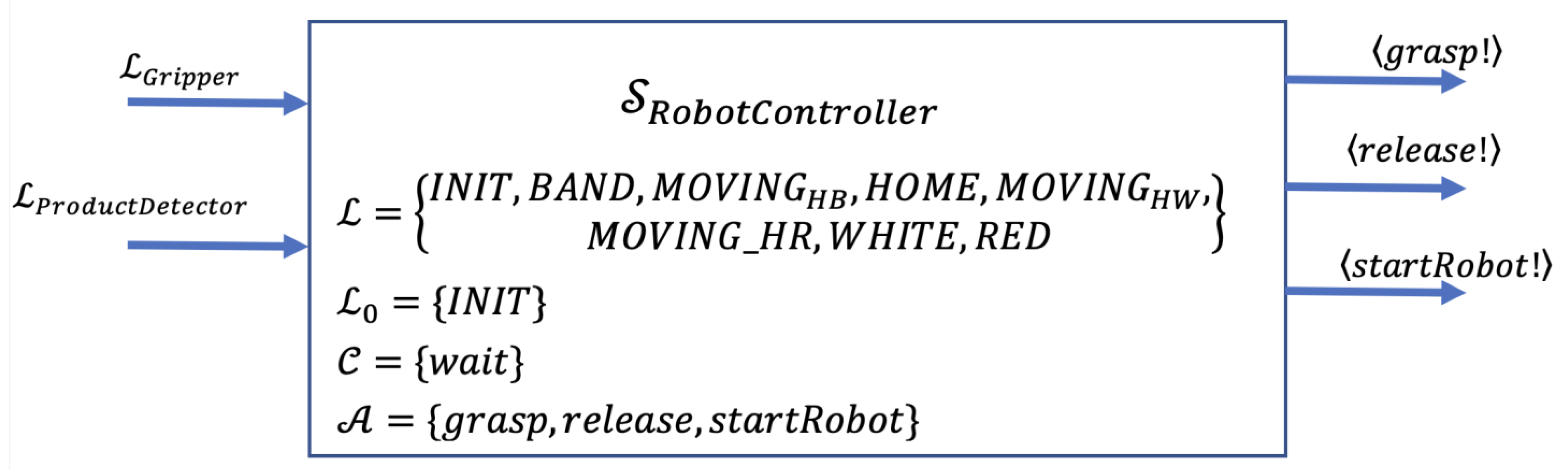
Figure 7 presents the block diagram of the robot controller module, which indicates the actions and states related to other modules.
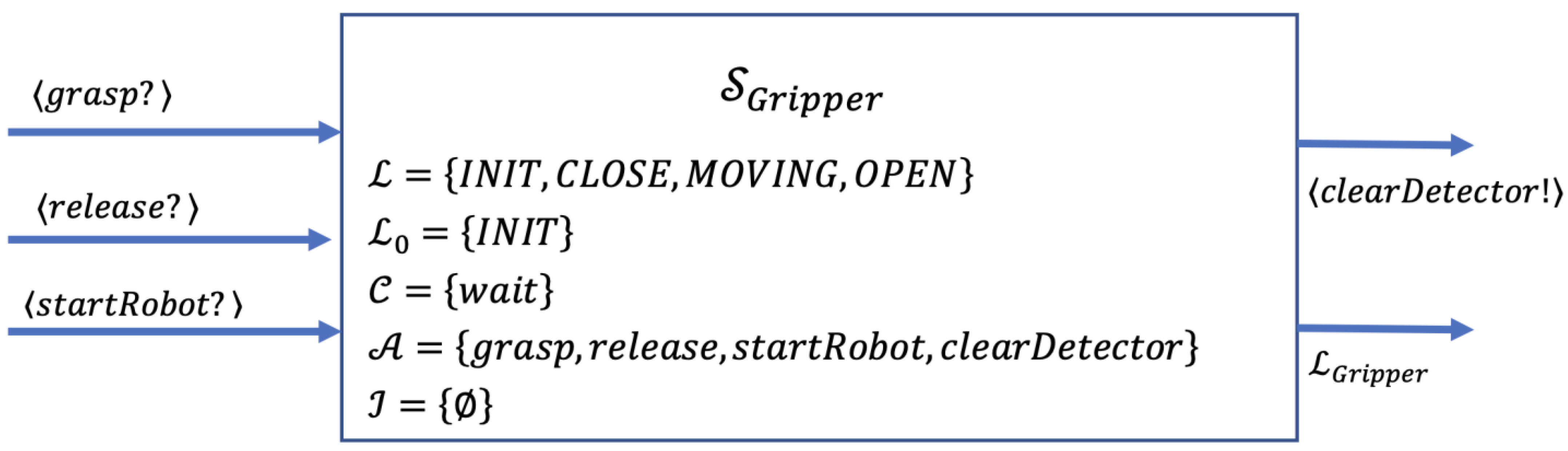
3.2.2. Gripper
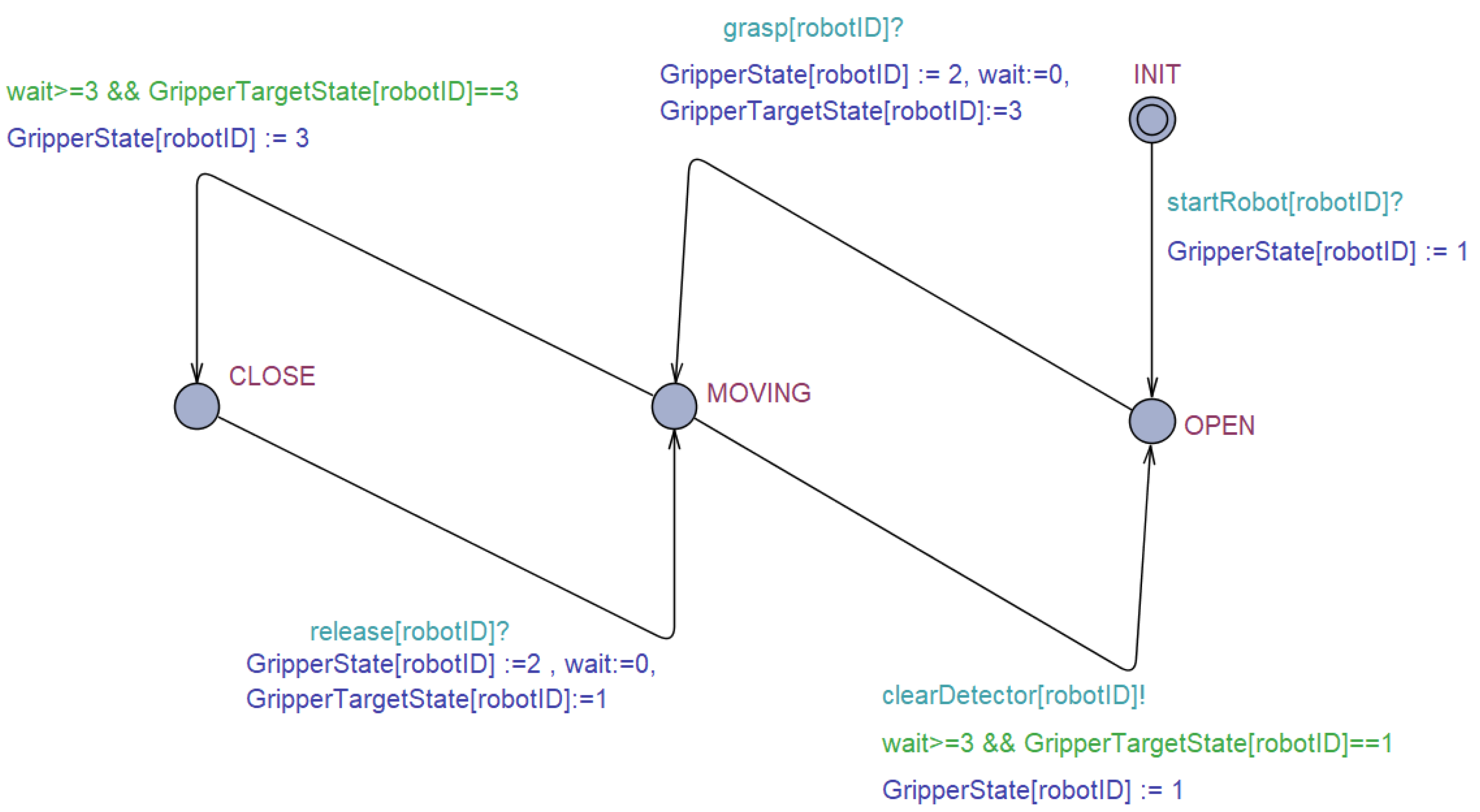
The gripper template has two primary states: OPEN and CLOSE, as shown in
Figure 8. When the robot starts running, it triggers the gripper to pass to
. Whenever it takes the action to grasp, the gripper passes to the state
. Conversely, whenever it takes the action to release, it triggers the gripper to turn back to
. When the gripper passes between CLOSE and OPEN, it takes time for the motion to be completed. Therefore, the state MOVING is needed to represent the gripper motion. It is assumed that the
state takes three units of time.
The state transition system for the gripper can be defined as follows:
Figure 9 presents the block diagram of the gripper module, which indicates the actions and states related to other modules.
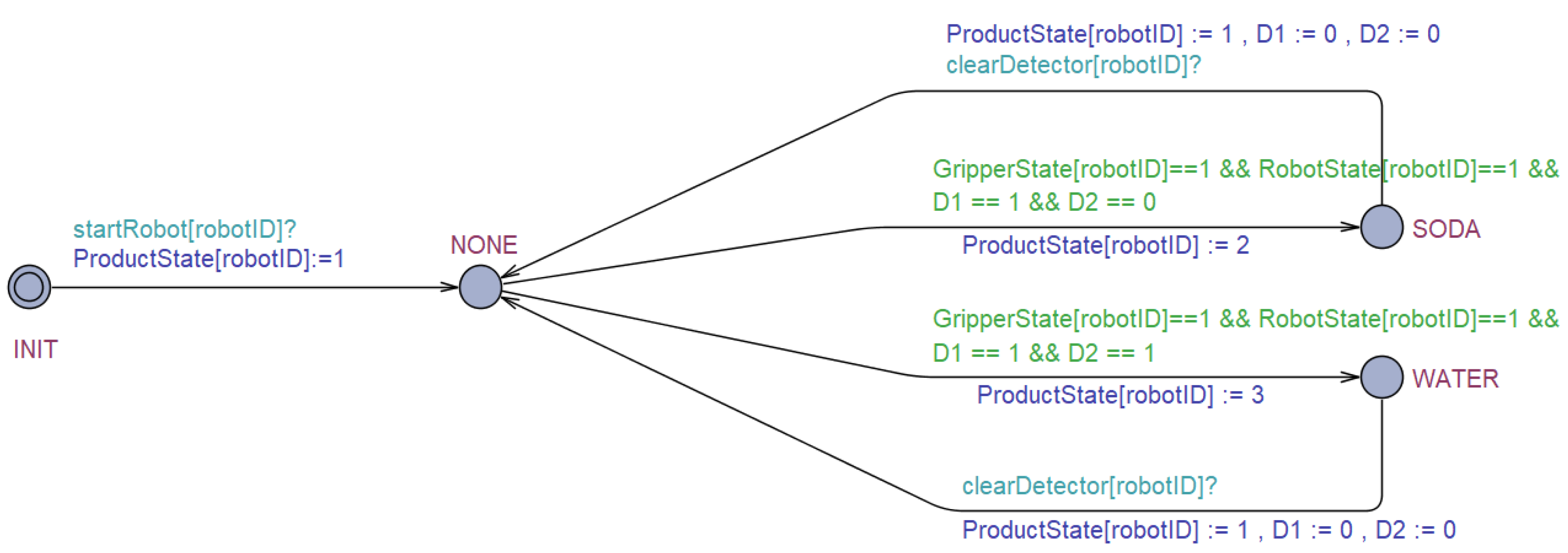
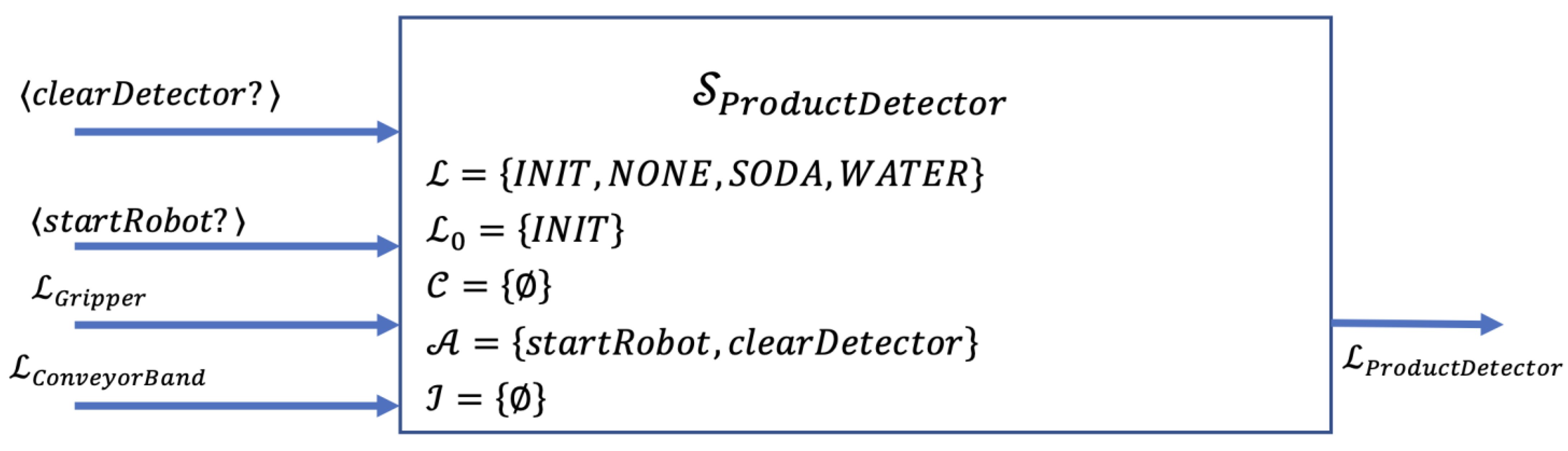
3.2.3. Product Detector
The gripper has two distance sensors, namely D1 and D2, which read two different values to detect soda and water. The detection results constitute the state of the product detector, such as SODA, WATER, and NONE.
Figure 10 shows the timed automata of the product detector.
The state transition system for the gripper can be defined as follows:
Figure 11 presents the block diagram of the product detector module, which indicates the actions and states related to other modules.
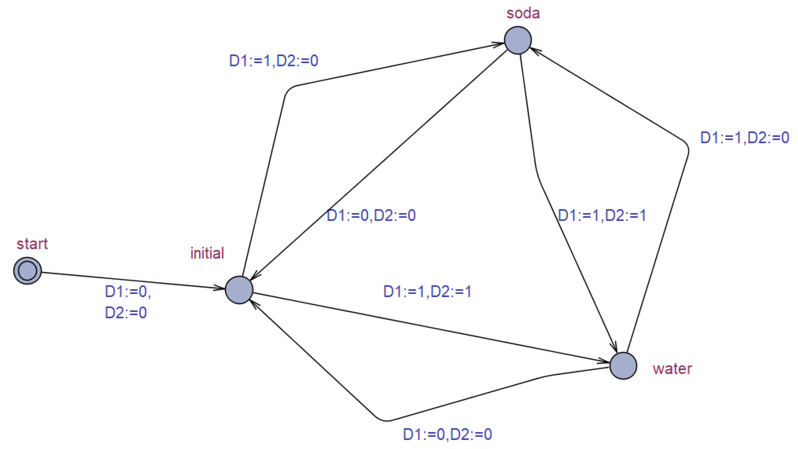
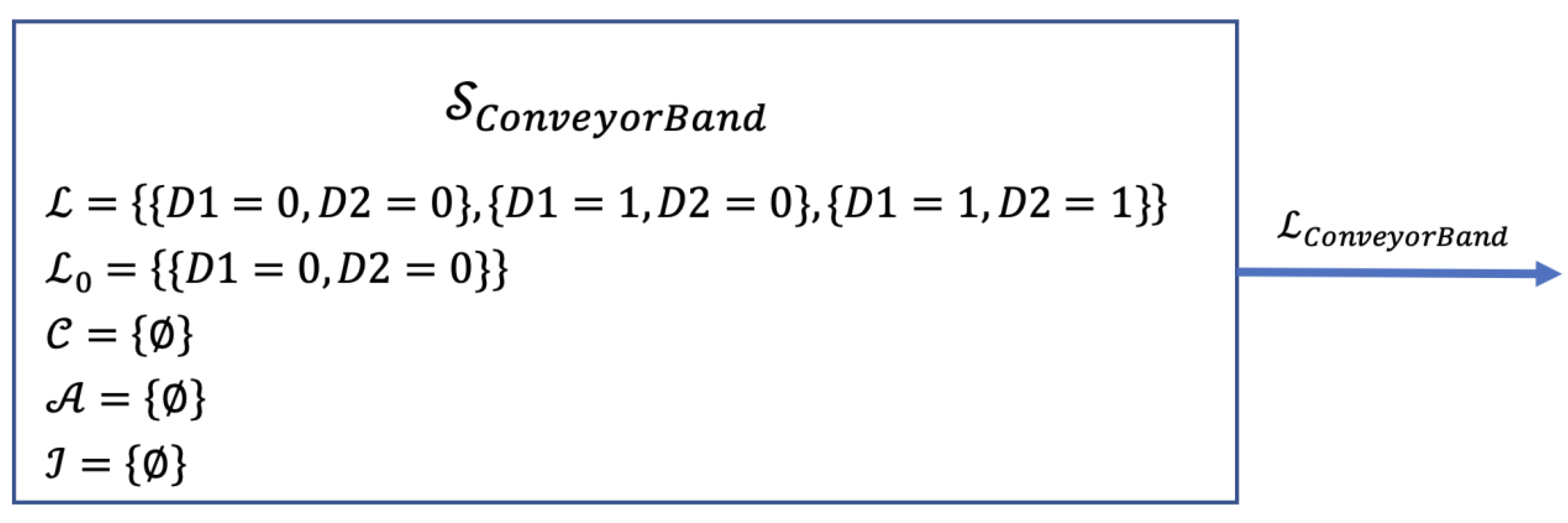
3.2.4. Conveyor Band
The conveyor band is simply a driver system that simulates the presence of soda and water nondeterministically appearing on the band. There are three states,
,
and
, as shown in
Figure 12. Each state represents the various configuration of the distance sensor readings
.
The state transition system for the gripper can be defined as follows:
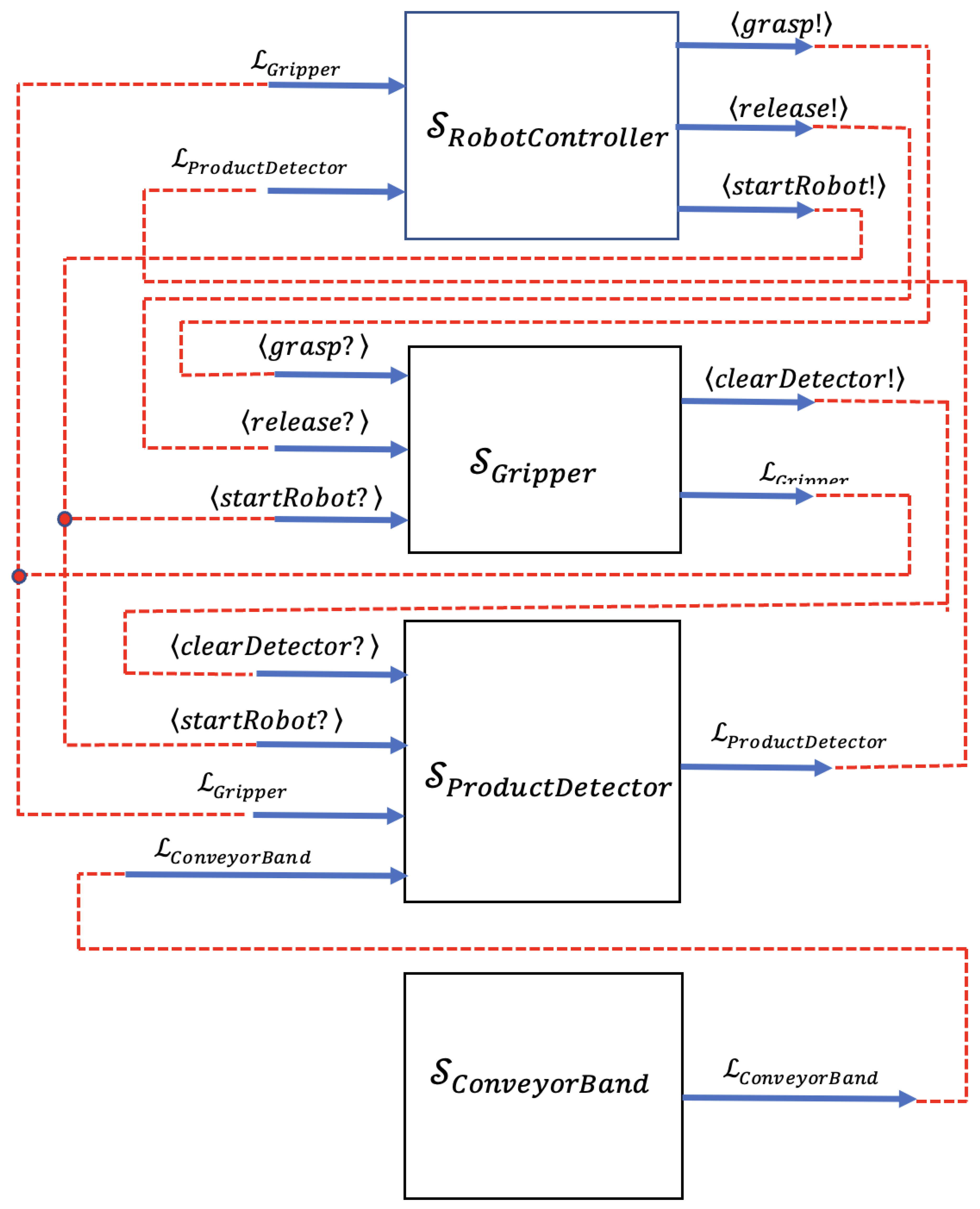
Figure 13 presents the block diagram of the conveyor band module, which indicates the actions and states related to other modules. It is a driver module in order to use the verification of the overall model. It is not a part of the system software.
The block diagram including all of the modules and their relationships is shown in
Figure 14.
3.3. Continuous Time Markov Chains (CTMC) Modeling
PRISM is one of the model-checking tools used to verify a probabilistic system. It can build and analyze many types of probabilistic models. There are three modules for describing the system models: the robot controller, gripper, and product detector. The robot controller module is modeled for each robot separately because of the differences between the behavior of the robots, as shown in Algorithms 1 and 2. On the other hand, there are one gripper and one product detector module. Due to the similar functionalities of each robot, multiple instances of these modules can be used.
| Algorithm 1. PRISM CTMC model of robot controller1. |
ctmc
globalredRegion: bool init false;
global white region : bool init false;
// R1 denotes robot which is located left side conveyor band, as well as R2 denotes the right one.
module RobotController1
// robot states =>> [ 0: INIT, 1: BAND, 2: HOME, 3: RED, 4: WHITE, 5: MOVING_BH, 6:MOVİNG_HR, 7:MOVİNG_HW ]
robotState1 : [0..7] init 0;
robotTargetState1 : [0..7] init 0;
robotPreState1 : [0..7] init 0;
// BAND <-> HOME
// Init -> Band
[startRobot1] robotState1 = 0 -> ( robotState1’ = 1 ) & ( robotPreState1’ = 0 );
// Band -> Band
[grasp1] robotState1 = 1 & gripperState1 = 1 & productState1 != 1 -> ( robotState1’ = 1 );
// Band -> Moving_BH
[] robotState1 = 1 & gripperState1 = 3 -> ( robotState1’ = 5 ) & ( robotTargetState1’ = 2 ) & ( robotPreState1’ = 1 );
// Moving_BH -> Home
[] robotState1 = 5 & robotTargetState1 = 2 -> ( robotState1’ = 2 ) ;
// Home -> Moving_BH
[] robotState1 = 2 & gripperState1 = 1 -> ( robotState1’ = 5 ) & ( robotTargetState1’ = 1 ) & ( robotPreState1’ = 2 );
// Moving_BH -> Band
[] robotState1 = 5 & robotTargetState1 = 1 -> (robotState1’ = 1 );
// HOME <-> RED
// Home -> Moving_HR
[] robotState1 = 2 & productState1 = 2 & redRegion = false & whiteRegion = false ->
( robotState1’ = 6 ) & ( robotTargetState1’ = 3 ) & ( redRegion’ = true ) & ( whiteRegion’ = true ) & ( robotPreState1’ = 2 );
// Moving_HR -> Red
[] robotState1 = 6 & robotTargetState1 = 3 -> ( robotState1’ = 3 );
// Red -> Red
[release1] robotState1 = 3 -> ( robotState1’ = 3 );
// Red -> Moving_HR
[] robotState1 = 3 & gripperState1 = 1 -> ( robotState1’ = 6 ) & ( robotTargetState1’ = 2 ) & ( robotPreState1’ = 3 );
// Moving_HR -> Home
[] robotState1 = 6 & robotTargetState1 = 2 -> ( robotState1’ = 2 ) & ( redRegion’ = false ) & ( whiteRegion’ = false ) ;
// HOME <-> WHITE
// Home -> Moving_HW
[] robotState1 = 2 & productState1 = 3 & whiteRegion = false ->
( robotState1’ = 7 ) & ( robotTargetState1’ = 4 ) & ( whiteRegion’ = true ) & ( robotPreState1’ = 2 );
// Moving_HW -> White
[] robotState1 = 7 & robotTargetState1 = 4 -> ( robotState1’ = 4 ) ;
// White -> White
[release1] robotState1 = 4 -> ( robotState1’ = 4 );
// White -> Moving_HW
[] robotState1 = 4 & gripperState1 = 1 -> ( robotState1’ = 7 ) & ( robotTargetState1’ = 2 ) & ( robotPreState1’ = 4 );
// Moving_HW -> Home
[] robotState1 = 7 & robotTargetState1 = 2 -> ( robotState1’ = 2 ) & ( whiteRegion’ = false );
endmodule |
| Algorithm 2. PRISM CTMC model of robot controller2. |
module RobotController2
// robot states =>> [ 0: INIT, 1: BAND, 2: HOME, 3: RED, 4: WHITE, 5: MOVING_BH, 6:MOVİNG_HR, 7:MOVİNG_HW ]
robotState2 : [0..7] init 0;
robotTargetState2 : [0..7] init 0;
robotPreState2 : [0..7] init 0;
// BAND <-> HOME
// Init -> Band
[startRobot2] robotState2 = 0 -> ( robotState2’ = 1 ) & ( robotPreState2’ = 0 );
// Band -> Band
[grasp2] robotState2 = 1 & gripperState2 = 1 & productState2 != 1 -> ( robotState2’ = 1 );
// Band -> Moving_BH
[] robotState2 = 1 & gripperState2 = 3 -> ( robotState2’ = 5 ) & ( robotTargetState2’ = 2 ) & ( robotPreState2’ = 1 );
// Moving_BH -> Home
[] robotState2 = 5 & robotTargetState2 = 2 -> ( robotState2’ = 2 ) ;
// Home -> Moving_BH
[] robotState2 = 2 & gripperState2 = 1 -> ( robotState2’ = 5 ) & ( robotTargetState2’ = 1 ) & ( robotPreState2’ = 2 );
// Moving_BH -> Band
[] robotState2 = 5 & robotTargetState2 = 1 -> (robotState2’ = 1 );
// HOME <-> RED
// Home -> Moving_HW
[] robotState2 = 2 & productState2 = 3 & whiteRegion = false & redRegion = false ->
( robotState2’ = 7 ) & ( robotTargetState2’ = 4 ) & ( whiteRegion’ = true ) & ( redRegion’ = true ) & ( robotPreState2’ = 2 );
// Moving_HR -> White
[] robotState2 = 7 & robotTargetState2 = 4 -> ( robotState2’ = 4 ) ;
// White -> White
[release2] robotState2 = 4 -> ( robotState2’ = 4 );
// White -> Moving_HR
[] robotState2 = 4 & gripperState2 = 1 -> ( robotState2’ = 7 ) & ( robotTargetState2’ = 2 ) & ( robotPreState2’ = 4 );
// Moving_HR -> Home
[] robotState2 = 7 & robotTargetState2 = 2 -> ( robotState2’ = 2 ) & ( whiteRegion’ = false ) & ( redRegion’ = false ) ;
// HOME <-> WHITE
// Home -> Moving_HR
[] robotState2 = 2 & productState2 = 2 & redRegion = false ->
( robotState2’ = 6 ) & ( robotTargetState2’ = 3 ) & ( redRegion’ = true ) & ( robotPreState2’ = 2 );
// Moving_HW -> Red
[] robotState2 = 6 & robotTargetState2 = 3 -> ( robotState2’ = 3 ) ;
// Red -> Red
[release2] robotState2 = 3 -> ( robotState2’ = 3 );
// Red -> Moving_HW
[] robotState2 = 3 & gripperState2 = 1 -> ( robotState2’ = 6 ) & ( robotTargetState2’ = 2 ) & ( robotPreState2’ = 3 );
// Moving_HW -> Home
[] robotState2 = 6 & robotTargetState2 = 2 -> ( robotState2’ = 2 ) & ( redRegion’ = false ) ;
endmodule |
In summary, the robot controller module has three main transitions between the state couples given as (HOME, BAND), (HOME, RED), and (HOME, WHITE). All possible transitions between these states and substates (MOVING_BH, MOVING_HR, MOVING_HW) are defined by actions, guards, and state updates.
The model of the gripper module is given in Algorithm 3. The transitions between the states OPEN and CLOSE occur as a result of the actions named startRobot, grasp, release, and clearDetector.
The model of the product detector module is given in Algorithm 4. There are two different objects on the conveyor belt, and the probability of their arrival is assumed to be the same. Therefore, both have a 50% probability of arrival, as shown in Algorithm 4. After the choice is made randomly, the gripper module is triggered by the robot controller and the object is grasped.
| Algorithm 3. PRISM CTMC model of gripper. |
module GripperTool1
// gripper states =>> [ 0: START, 1: OPEN, 2: MOVING, 3: CLOSE ]
gripperState1 : [0..3] init 0;
gripperTargetState1 : [0..3] init 0;
// Start -> Open
[startRobot1] gripperState1 = 0 -> ( gripperState1’ = 1 );
// Open -> Moving
[grasp1] gripperState1 = 1 -> ( gripperState1’ = 2 ) & ( gripperTargetState1’ = 3 );
// Moving -> Close
[] gripperState1 = 2 & gripperTargetState1 = 3 -> ( gripperState1’ = 3 );
// Closed -> Moving
[release1] gripperState1 = 3 -> ( gripperState1’ = 2 ) & ( gripperTargetState1’ = 1 );
// Moving -> Open
[clearDetector1] gripperState1 = 2 & gripperTargetState1 = 1 -> ( gripperState1’ = 1 ) ;
endmodule |
| Algorithm 4. PRISM CTMC model of product detector. |
module ProductDetector1
// sensor states =>> [ 0: Init, 1: None, 2: Soda, 3: Water ]
productState1 : [0..3] init 0;
// Init -> None
[startRobot1] productState1 = 0 -> ( productState1’ = 1 );
// None -> Soda (id : 2) | Water (id : 3)
[] productState1 = 1 & gripperState1 = 1 & robotState1 = 1 ->0.5: ( productState1’ = 2 ) + 0.5: ( productState1’ = 3) ;
// water | soda -> None
[clearDetector1] productState1 = 2 | productState1 = 3-> ( productState1’ = 1 );
endmodule |
Unlike the robot controller module, the gripper and the product detector modules do not need to be modelled separately for each robot. Therefore, the only requirement is to create a new module instance by replacing the local variables with new ones, as shown in Algorithm 5.
| Algorithm 5. PRISM straightforward way to create a new module from an existing one. |
module GripperTool2=GripperTool1[gripperState1=gripperState2,gripperTargetState1=gripperTargetState2,
startRobot1=startRobot2,grasp1=grasp2,release1=release2,clearDetector1=clearDetector2] endmodule
module ProductDetector2=ProductDetector1[productState1=productState2,startRobot1=startRobot2,
gripperState1=gripperState2,robotState1=robotState2,clearDetector1=clearDetector2] endmodule |
5. Results and Evaluation
A case study for multiple industrial robot manipulators with path conflicts is discussed. The software of the robotic system in our case study was developed by a model-based approach. First, a state-based verification model of the system was created in order to be verified by two model checker tools, UPPAAL and PRISM.
UPPAAL and PRISM are model-checking tools capable of verifying systems against given specifications. Both tools are used for modeling and verification. However, each tool has strengths and weaknesses compared to others. UPPAAL is more suitable for real-time systems modeled as networks of timed automata, while PRISM is suitable for developing probabilistic models. Furthermore, UPPAAL allows the modeling of the system via a GUI, but the modeling process in PRISM is code-based [
32]. Therefore, modeling in PRISM requires more attention than in UPPAAL. Both consist of a simulator that enables the examination of possible dynamic executions of a system. Moreover, their verifier can detect syntax errors, but properties must be verified through the verifier. UPPAAL uses a subset of CTL as its property specification language, but PRISM utilizes logic such as LTL and PCTL. In addition, there is a difference in model constructions that can be inspected from
Figure 5 and Algorithms 1 and 2. The model of the robot controller can be described as a template in UPPAAL. Furthermore, the template is instantiated by two processes for robots R1 and R2. However, in PRISM, the robots R1 and R2 are described in two separate modules.
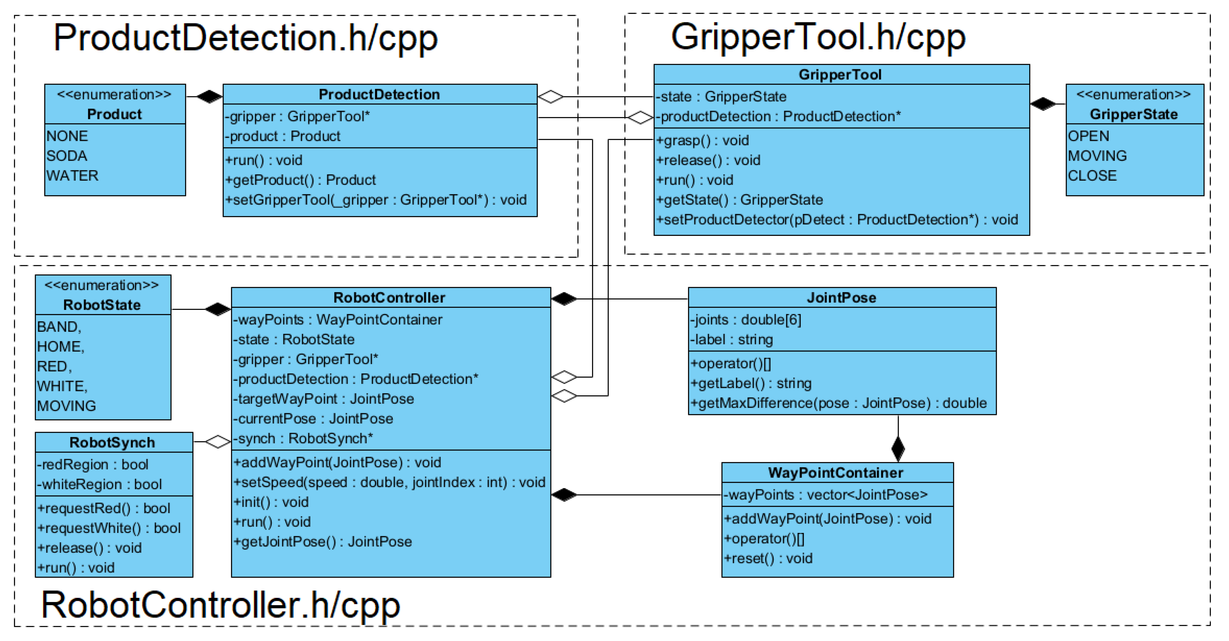
After the model of the system was verified by meeting the desired requirements, then the control software of the system could be developed to reflect the verified model. The object-oriented design approach was employed to implement the control software. The UML class diagram of the system is given in
Figure 15. run() methods of each class implement the related state transition models, which are verified for meeting the requirements. The classes are coded in C++.
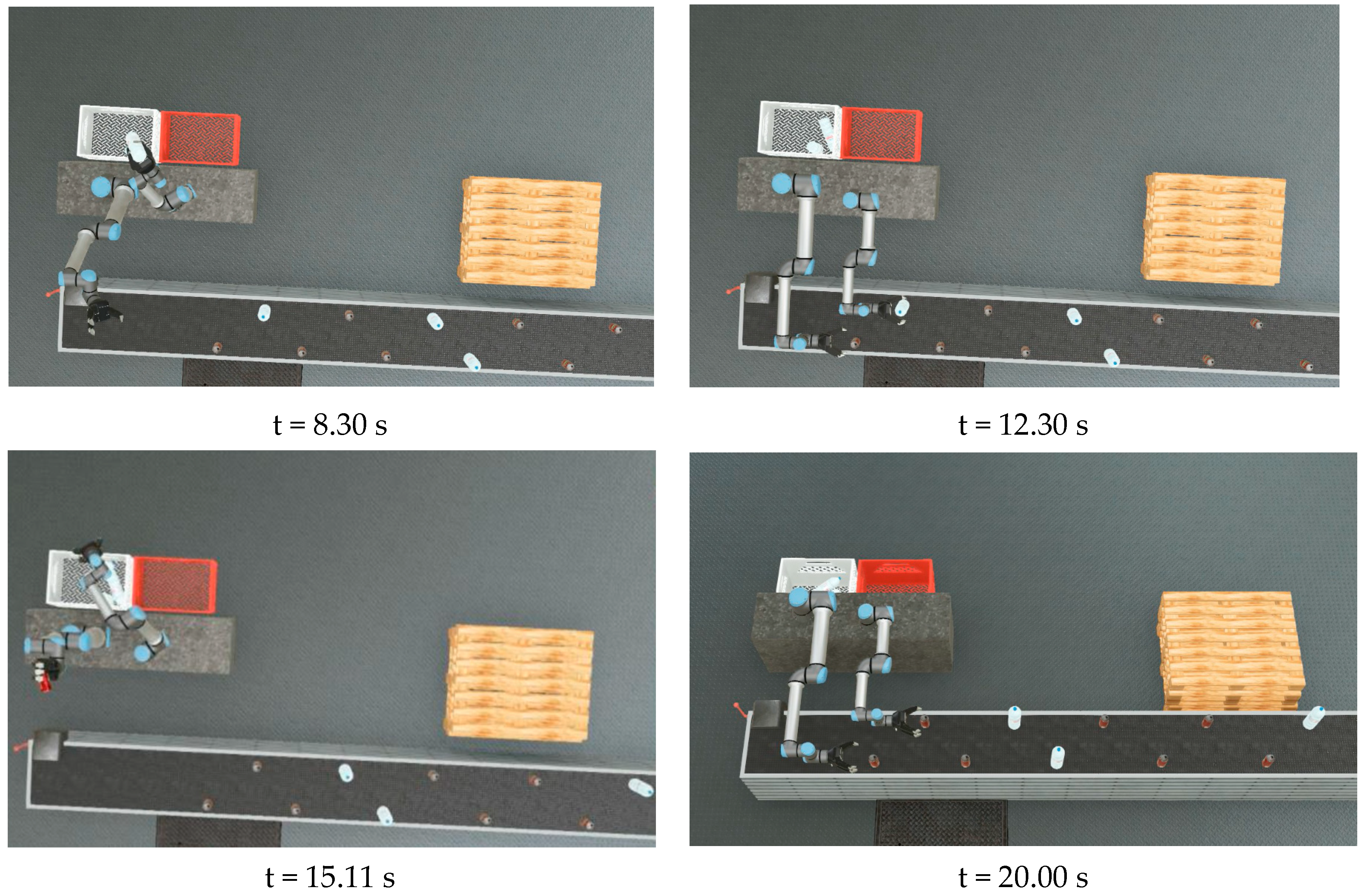
The simulation environment was constructed by using WEBOTS. Then, the robot program was run in the simulation environment. The products soda and water moved randomly on the conveyor band. During the execution, it was seen that the requirements were met.
Figure 16 shows some snapshots from the simulations. The complete simulation video can be watched at the link
https://youtu.be/V_Tpsp5NUA0 (accessed on 3 January 2023). At
, the grippers mounted on the robot arms are over the conveyor band, and the products are coming through the grippers. Before
, both robot arms hold a water bottle and move towards the white crate at almost the same time. Furthermore, at
, robot R2 is waiting for R1 while robot R1 is dropping the bottle and returning to the position HOME. Then, at
, the robot R2 also moves toward the white crate and drops the bottle. Similarly, at
, R1 grabs a soda can while R2 grabs a water bottle. In this case, R1 waits at HOME until R2 returns HOME after dropping the water bottle into the white crate.


