Article

Interleaving Modulation Schemes in Asymmetrical Dual Three-Phase Machines for the DC-Link Stress Reduction

Department of Electronic Technology, Faculty of Engineering in Bilbao, University of the Basque Country (UPV/EHU), Plaza Ingeniero Torres Quevedo 1, 48013 Bilbao, Spain
*
Author to whom correspondence should be addressed.
Machines 2023, 11(2), 267; https://doi.org/10.3390/machines11020267
Submission received: 13 January 2023 / Revised: 1 February 2023 / Accepted: 7 February 2023 / Published: 10 February 2023
(This article belongs to the Special Issue Multiphase Machines: Converter Control and Innovative Exploitation)

Abstract

:
The DC-Link capacitor plays a crucial role as far as power density and reliability are concerned: it occupies approximately 40% of the inverter, and causes approximately 30% of its failures. Asymmetrical dual three-phase (ADTP) multiphase arrangements are gaining relevance in the automotive sector for powertrain applications. This work focuses on reducing the impact that the widely used double zero sequence injection (DZSI) family of PWM techniques have on such a bulky and failure-prone component in an ADTP arrangement by means of interleaving techniques. By using the double Fourier integral formalism, the input current spectra and the overall performance of these PWM techniques have been derived, in terms of current rms value and voltage ripple in the DC-Link capacitor. Simulations have shown that choosing an adequate interleaving scheme and angle considerably relieves both current and voltage stresses on the DC-Link capacitor compared to noninterleaved operation. Reductions of 84% current rms and 86% voltage ripple have been achieved at static operating points. Finally, by averaging the rms current over WLTP standard driving cycle, reductions up to 26% have been obtained under more realistic conditions. All this would enhance the reliability and reduce the size of the onboard capacitors in future electric vehicles.

1. Introduction

The electric vehicle (EV) powertrain is experimenting a huge change. WBG semiconductors, motors without dependence on rare earth materials and new converter architectures are being introduced. Automotive manufacturers and international programs such as Horizon Europe, USCAR, DOE, and UN ESCAP are focusing on improving specific power (kW/kg), power density (kW/), efficiency (%), and cost ($/kW) [1]. In this context, multiphase propulsion systems provide several advantages at an affordable cost compared with classic three-phase electric motor-driven systems. Such benefits include power splitting between phases (lower currents and power losses for the same rated output power), reduction of the torque ripple (enhanced efficiency), torque density improvement using harmonic current injection (in concentrated winding machines), lower DC-Link current ripples (smaller DC-Link capacitor), and intrinsic fault-tolerant operation [2,3,4,5].
In order to benefit from the abovementioned advantages of multiphase systems, the recent scientific literature shows that the dual three-phase topology (Figure 1) is probably the most widespread multiphase solution [6,7,8,9,10]. Although odd phase number multiphase star-connected arrangements offer a better relationship between the degrees of freedom and the phase number and semiconductor device number, they have lower fault tolerance regarding short circuit and power supply faults (when dual three-phase arrangements are supplied independently) and their modulation scheme is more complex [11]. Therefore, multiple three-phase winding machines are preferred. Theoretically, any number of three-phase winding sets can constitute this kind of electric machine; the most common is to find dual three-phase arrangements with two isolated neutral points known as “dual three-phase” [12]. These configurations are the most interesting because (i) they represent a good tradeoff between performance and complexity; (ii) easy migration from three-phase technologies is possible because multiple generic and modular three-phase inverters can feed the two three-phase winding sets independently [13]; and (iii) they have very good performance in terms of fault tolerance (open and short circuit faults as well as on the DC power supply) [6,7,14,15]. Generally, 0°, 30°, and 60° are the preferred angle displacements between the two sets. However, the 30° type, which is commonly called asymmetrical six-phase or asymmetrical dual three-phase (ADTP) machine (Figure 1), provides higher torque density and lower torque ripple than the others [16] because it eliminates the sixth torque harmonic pulsation through the synchronization of the two winding sets [17,18].
Thus, ADTP-specific voltage-source inverters (VSIs) have been developed, which show great potential in safety-critical applications, and when high power density is needed, such as in electric vehicle (EV) drivetrains [19]. These VSIs (Figure 1) can be controlled by using either appropriate space vector (SV) [20,21,22,23,24] or carrier-based (CB) [25,26,27,28,29,30] PWM techniques. There is a wide variety of SV-PWM techniques for the ADTP topology; some of them utilize two large adjacent active vectors to synthesize the reference voltage vector [20], and others use four large active vectors [20,21], three large active vectors plus one medium active vector [22], or two large and two medium active vectors [23]. In contrast, CB-PWM strategies are usually treated as a dual three-phase structure (VSI1 and VSI2, Figure 1), instead of a six-phase system. This implies an advantage over the SV-based approach because conventional CB-PWM techniques can be exploited. Figure 2 shows how these three-phase CB-PWM techniques are implemented, where v * = M cos ( θ 1 ) is the modulating signal, v 0 s is the injected zero-sequence component, v * * = v * + v 0 s is the modified modulating signal, θ 1 is the modulating signal’s angular position and the modulation index (M) is defined as M = V ^ 1 / 0.5 · V D C [31], where V ^ 1 is the peak phase-neutral voltage and V D C is the DC-Link voltage (Figure 1).
CB-PWM techniques applied in a “split” six-phase inverter are commonly known as double zero-sequence injection (DZSI) PWM techniques because this implies injecting one zero-sequence component ( v 0 s ) into each three-phase structure [25]. They can be classified into continuous and discontinuous modulation techniques [31]. Sinusoidal PWM (SPWM, as the zero sequence signal which is injected in SPWM is 0, sometimes it is not considered as DZSI-PWM technique), third harmonic injection PWM (THI-PWM) and min-max PWM method (MINMAX-PWM, sometimes also called symmetrical SV-PWM) are known as continuous modulations (C-PWM), in which all the inverter branches switch continuously. D-PWMMIN, D-PWMMAX, D-PWM0, D-PWM1, D-PWM2, and D-PWM3 are known as discontinuous PWM (D-PWM) techniques, in which one branch does not switch over a whole switching period (while the modulating signal is clamped to ± 1 , Figure 2). Thus, the switching power losses in the semiconductors of the VSI are reduced for discontinuous PWM techniques because only two out of the three branches are actually switching and the average equivalent switching frequency is reduced to 2 / 3 f s w . Finally, all these carrier-based PWM techniques allow a maximum modulation index M m a x = 1.15 working in the linear region except for SPWM technique in which M m a x = 1 .
At hardware level, the DC-Link capacitor ( C D C , Figure 1) is a crucial element of the VSI. This capacitor is responsible for reducing the low-frequency voltage ripple at the input of the converter, in both steady and transient states, as well as storing the necessary energy to allow an instantaneous power balance between the converter input and output. It must provide a low impedance path for high-frequency currents in order to decouple and reduce the current ripple from the battery. More importantly, in traction applications, the DC-Link capacitor is a bulky and expensive component because it amounts to up to 40% of the total volume of the VSI [32,33,34,35]. In addition, DC-Link capacitors are also considered to be one of the most critical elements in power electronics because they cause 30% of the total failures in power electronic inverters [36,37,38]. For this reason, the reliability of these reactive components has been discussed deeply during the last several years [39,40,41,42].
The selection of the DC-Link capacitor (technology, capacitance, size, weight, cost, etc.) is highly dependent on the DC voltage rating of the application where they are integrated [40]. To date, light EV batteries ranged from 250 to 450 V [43], whereas for heavy vehicles the rated voltage is about 800 V. In this context, a trend change is taking place in which electric mobility manufacturers are committed to offering more solutions for these 800-V systems, because this permits the utilization of lighter wiring [44] and also produces smaller on-state power losses, higher efficiency and power density motors, and faster charge of the battery pack [45]. At higher DC voltages, the capacitance of C D C decreases for the same size or encapsulation [46], and its lifetime is significantly reduced. For example, AVX automotive film capacitors of the FHC1 series has a lifetime of an order of magnitude of 10,000 h at 400 V, whereas at 900 V the lifetime drops to approximately 1000 h [46].
In addition to the DC voltage rating, there are other important specifications to select an appropriate DC-Link capacitor: voltage ripple, which is inversely proportional to the capacitance and the size of the DC-Link capacitor [47,48], and current ripple [32,34,49]. Any voltage ripple on the DC-Link produces an additional current ripple on the phase currents, which worsens torque ripple in the electric machine. In this context, there is often a specification for the maximum allowable voltage ripple on the DC-Link (typically ranging from 5–10%).
The current ripple is conditioned by the maximum hot-spot temperature of the DC-Link capacitor. This internal temperature depends on the power losses due to the equivalent series resistance (ESR) and is inversely proportional to the lifetime of the component. Thus, manufacturers typically specify the maximum rms ripple current rating at an ambient temperature and a specific frequency.
Because the DC-Link capacitor is a critical component, significant efforts are being made to enhance its performance. Some works propose to minimize the DC-Link capacitor’s current stress by the synchronization of parallel-interleaved single-phase inverters [50,51] and three-phase inverters [52,53,54,55,56,57,58,59]. In ADTP machines, constant interleaving angles can be used to reduce the DC-Link capacitor current for the MINMAX-PWM and some discontinuous PWM techniques [49,60,61,62]. Ref. [63] proposes a dynamic interleaving method to reduce the DC-Link current ripple, which is only applicable to discontinuous PWM techniques.
However, it is not common to find research works that analyse in-depth the effect of the interleaving angle on the input harmonic cancellation and the rms current minimization of the ADTP arrangement. Furthermore, the few existing contributions usually focus on one or two specific PWM techniques, which makes it hard to compare and quantify the performance of the various DZSI-PWM techniques. As a result, identifying the best interleaving angle for each DZSI-PWM technique applied in an ADTP arrangement is also missing in the scientific literature.
This paper focuses on reducing the current and voltage stress in the DC-Link capacitor by using a multiphase VSI and DZSI-PWM techniques suitable for ADTP arrangement. Different aspects are discussed throughout the paper. In Section 2, DC-Link current spectra are analysed by using the double Fourier integral method for DZSI-PWM techniques in ADTP converters, which are directly related to the main voltage and current stress variables (rms current and peak-to-peak voltage ripple) for the DC-Link capacitor. The figure-of-merit considered in the scientific literature is the output current quality, which is directly related to the total harmonic distortion (THD) or the flux harmonic distortion factor (HDF). However, this ignores how the modulation technique affects the converter input. Thus, Section 3 mathematically analyses and simulates the effect of the DZSI-PWM techniques on the input current spectrum and how it affects the DC-Link capacitor in an ADTP arrangement. Due to the need to reduce the rms value of the DC-Link capacitor current, Section 4 expresses different interleaving schemes and how the relationship between the input current harmonic spectrum and the constant interleaving can be exploited in order to cancel certain dominant harmonics. Next, in order to display the importance of using this type of interleaving techniques, Section 5 shows both the rms current and the peak-to-peak voltage of the DC-Link capacitor applying the optimal interleaving scheme for each DZSI-PWM technique. Finally, Section 6 draws the corresponding conclusions, emphasizing that the performance of the DC-Link capacitor can be significantly improved by applying a suitable interleaving scheme.

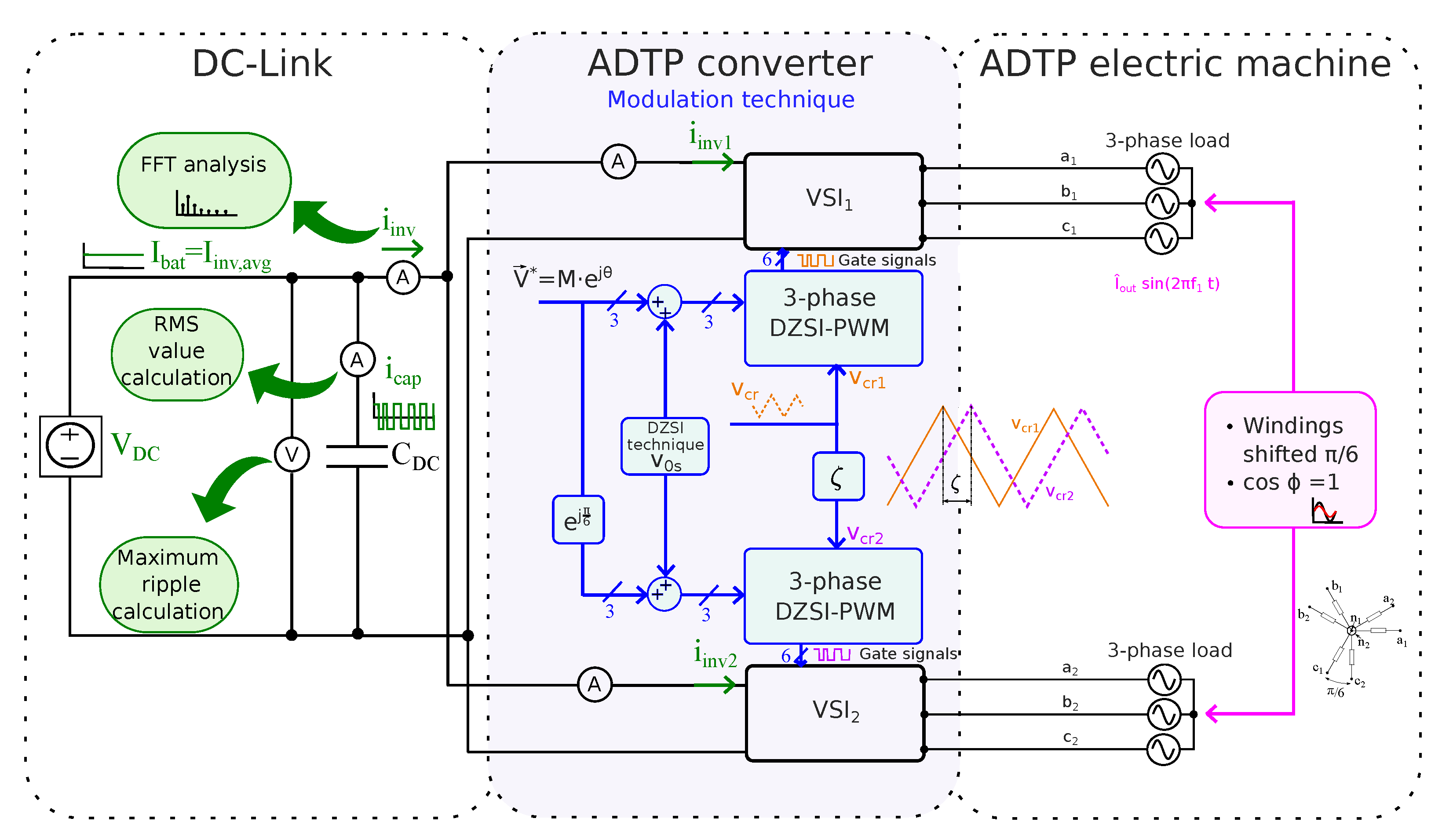
2. DC-Link Capacitor Current and Voltage Stress in Asymmetrical Dual Three-Phase Inverters

Voltage ripple and DC-Link capacitor current ( i c a p , Figure 1) rms value play a crucial role in the selection of an appropriate DC-Link capacitor. The current in the ADTP inverter determines the capacitor current. Figure 3 shows the detailed flow chart followed in this work in order to obtain the harmonic spectrum of the DC-Link capacitor for the described ADTP system. Here, two parallel procedures have been implemented: (i) in Matlab executing the corresponding code for the mathematical equations synthesized in this section; and (ii) in Matlab–Simulink by using a higher-level block environment. The current harmonic spectra obtained from both procedures have been compared to each other in order to check the result matching. In the next lines, the harmonic spectrum of the ADTP inverter is studied in detail.

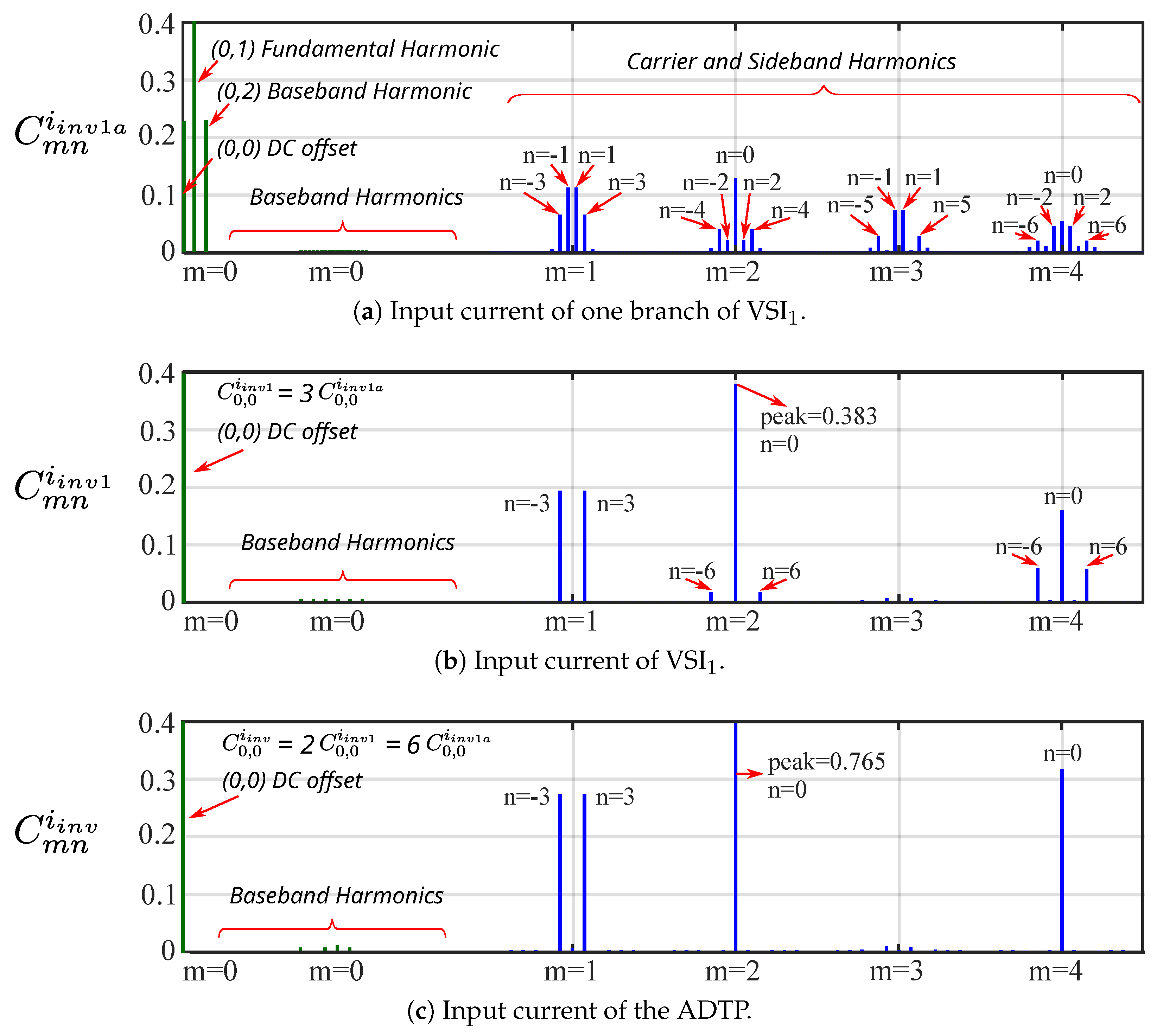
2.1. Current Spectrum Theoretical Basics for an ADTP Inverter

2.1.1. Input Current of One Branch of VSI1 ( i i n v 1 a )

The double Fourier integral formulation characterizes a double periodic function in the frequency domain [64]. Such is the case of a generic analog PWM waveform g x t , y t , where x t = 2 π f s w t and y t = 2 π f 1 t = θ 1 are two time variables, with f s w the carrier frequency and f 1 < f s w the fundamental frequency.
Thus, according to that formulation,
g x , y = A 00 2 DC   offset   + n = 1 A 0 n cos n y + B 0 n sin n y Fundamental ,   and Baseband Harmonics         + m = 1 A m 0 cos m x + B m 0 sin m x Carrier Harmonics   + n = but n 0 m = 1 A m n cos m x + n y + B m n sin m x + n y Sideband Harmonics   ,
where
A m n = 1 2 π 2 π π π π g x , y cos m x + n y d x d y ,
B m n = 1 2 π 2 π π π π g x , y sin m x + n y d x d y ,
or, in complex form,
C m n = A m n + j B m n = 1 2 π 2 π π π π g x , y e j m x + n y d x d y .
Thus, C m n = A m n 2 + B m n 2 represents the spectral magnitude of each harmonic, which arises at frequency values equalling f h = m f s w + n f 1 , where m is the carrier index variable and n is the baseband index variable.
Figure 2 and Figure 4 show how the voltage patterns of a PWM-driven inverter are synthesized as a function of the reference and carrier voltages, i.e., v * * and v c r , respectively. As is usual [65,66], let us assume that f s w f 1 ; therefore, the phase currents are sinusoidal, with amplitude I ^ o u t and phase lag ϕ without any high-frequency ripple current, so
i a 1 = I ^ o u t cos 2 π f 1 t ϕ = I ^ o u t cos y ϕ ;
then, because i i n v 1 a results from the sampling of i a 1 by following the same voltage PWM pattern, Equations (1)–(4) can be applied with
g ( x , y ) = 0 when v * * v c r , I ^ o u t cos y ϕ when v * * > v c r .
As Figure 4 shows, the limits of the inner integral for the rising and falling portions of g ( x , y ) equal x r = π 2 1 + v * * ( y ) and x f = π 2 1 + v * * ( y ) . Therefore, from (1)–(4) the harmonic coefficients of i i n v 1 a result [65,66] in
C m n i n v 1 a = I ^ o u t 2 π 2 0 2 π 1 + v * * ( y ) π 2 1 + v * * ( y ) π 2 cos y ϕ · e j m x + n y d x d y .
Thus, Equation (7) quantifies the spectrum of the current i i n v 1 a , emphasizing its dependance on the PWM technique and modulation index M through the limits of the inner integral v * * ( y ) as well as on the phase lag ϕ .

2.1.2. Input Current of VSI1 ( i i n v 1 )

The Fourier coefficients for the consecutive branches ‘1b’ and ’1c’ ( C m n i i n v 1 b and C m n i i n v 1 c ) of the VSI1 (Figure 1) can be obtained by taking (7) and replacing n y with n ( y + 2 π 3 ) and n ( y + 4 π 3 ) , respectively (the current pulses of this branches are phase shifted 2 π / 3 rad 4 π / 3 rad concerning the branch ‘1a’). Likewise, it can be phase shifted C m n i i n v 1 a as
C m n i i n v 1 b = C m n i i n v 1 a · e j n 2 π 3 ,
C m n i i n v 1 c = C m n i i n v 1 a · e j n 4 π 3 .
However, because i i n v 1 = i i n v 1 a + i i n v 1 b + i i n v 1 c (Figure 1),
C m n i i n v 1 = C m n i i n v 1 a · 1 + e j n 2 π 3 + e j n 4 π 3 = C m n i i n v 1 a · 1 + 2 cos n 2 π 3 ,
where, it can be inferred that C m n i i n v 1 = 0 for all values of n except for 0 and multiples of 3. This means that at the output phase currents of each three-phase VSI within the ADTP, where the harmonics multiples of 3 times the fundamental cancel each other out, at the input, the opposite happens. Thus, there only exist high-frequency carrier and sideband triplens harmonics at the converter input because the PWM methods eliminate all the low-order baseband harmonics.

2.1.3. Input Current of ADTP ( i i n v )

The ADTP is composed of two three-phase stator windings displaced spatially by 30 electrical degrees ( π / 6 rad). Usually, each three-phase subsystem has its own isolated neutral point (n1 and n2, Figure 1). Thus, following a similar analysis to (10), the Fourier coefficients for the input current harmonics of the second three-phase stator winding ( C m n i i n v 2 ) result in
C m n i i n v 2 = C m n i i n v 1 a · 1 + 2 cos n 2 π 3 · e j n π 6 ,
where e j n π 6 corresponds to the 30° displacement of the second stator winding with respect to the first one. From (10)–(11), the Fourier coefficients of the input current of the ADTP result in
C m n i i n v = C m n i i n v 1 a · 1 + 2 cos n 2 π 3 · 1 + e j n π 6 .
The difference among the input current harmonics of a three-phase system (10) and an asymmetrical dual three-phase VSI (12) is the 1 + e j n π 6 term, which equals 0 for n = 6 2 k + 1 k Z . This leads to the cancellation of some of the existing high-frequency carrier and sideband triplens harmonics at the input of each of the ADTP converter.

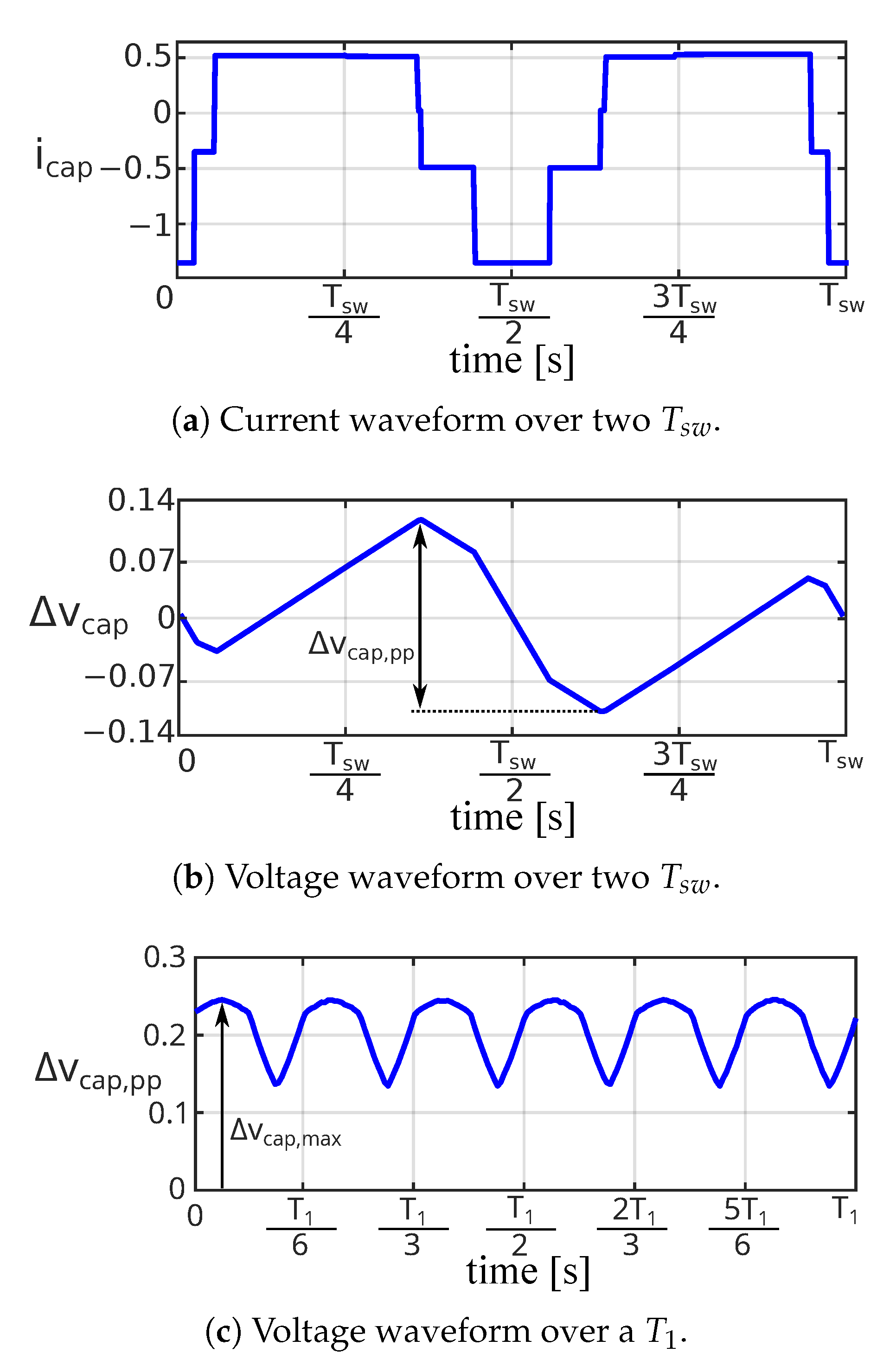
2.2. Definition of RMS Current and Voltage Ripple in DC-Link Capacitor

The worst scenario for the DC-Link capacitor is when the whole input current ripple of the ADTP comes from the DC-Link capacitor ( i c a p = i i n v , A C ) and the battery only supplies the average current of the inverter ( I b a t = I i n v , a v g ) [53,67,68,69,70]. Thus, the rms value of the DC-Link current (Figure 1) can be expressed as
I c a p , r m s = I i n v , r m s 2 I i n v , a v g 2 ,
where the rms value of the input current is
I i n v , r m s = n = 0 C 0 n i i n v 2 2 + m = 1 n = C m n i i n v 2 2 ,
and the average value of the input current of the ADTP is
I i n v , a v g = 6 4 M I ^ o u t cos ϕ .
Assuming that at the dominant current harmonic’s frequency the capacitor has a predominantly capacitive reactance, the RL impedance can be neglected, so the DC-Link voltage variation can be expressed as
Δ v c a p ( t ) = 1 C 0 t i c a p d t = 1 C 0 t ( i i n v I i n v , a v g ) d t .
Considering this, Figure 5a shows the current through the DC-Link capacitor and Figure 5b its voltage ripple according to (16). Applying a normalization factor Δ v b a s e = I ^ o u t · T s w / C to the voltage ripple of (16), the peak-to-peak value of the voltage ripple in every switching period ( T s w ) can be obtained by
Δ v c a p , p p T s w = m a x Δ v c a p ( t ) T s w m i n Δ v c a p ( t ) T s w ,
which makes it possible to determine the maximum value of the switching voltage ripple over T 1 (or θ 1 = 2 π rad ). Because the input current to the ADTP is repeated every 2 π / 6 rad (Figure 5c), it is sufficient to perform the analysis during this interval, so
Δ v c a p , m a x = m a x Δ v c a p , p p 2 π = m a x Δ v c a p , p p 2 π / 6 .

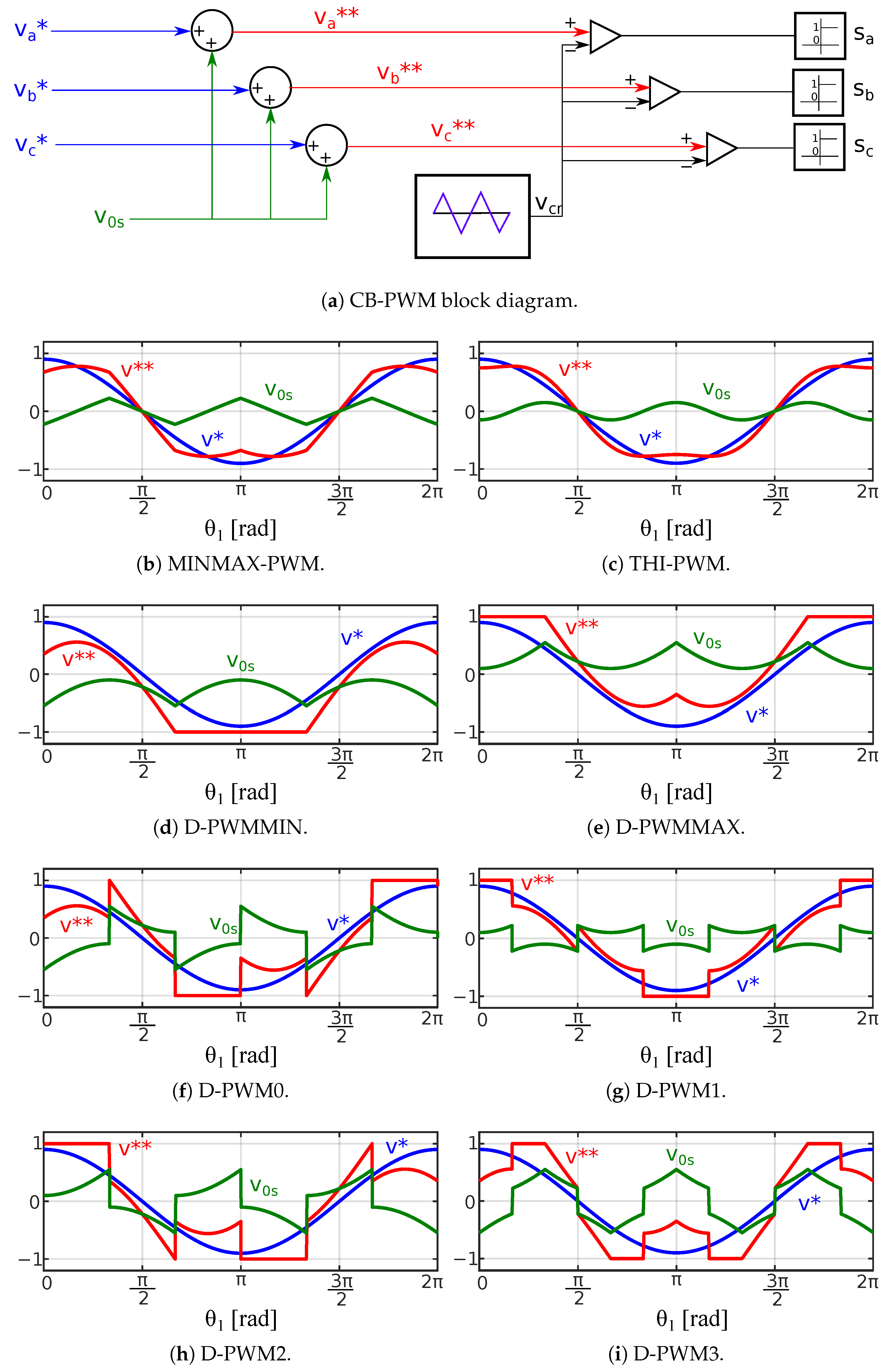
3. Influence of the Modulation Technique on the Input Current Harmonic Spectrum

Current harmonics mainly depend on the selected PWM technique, as well as on M, f h , and cos ϕ . Nevertheless, in most cases EV traction machines operate with a unitary cos ϕ [57] (this is demonstrated in Section 3.1). With the objective of simplifying the study, the input current spectra for different PWM techniques are obtained in Section 3.2 and Section 3.3 as a function of M, f h for cos ϕ = 1 .

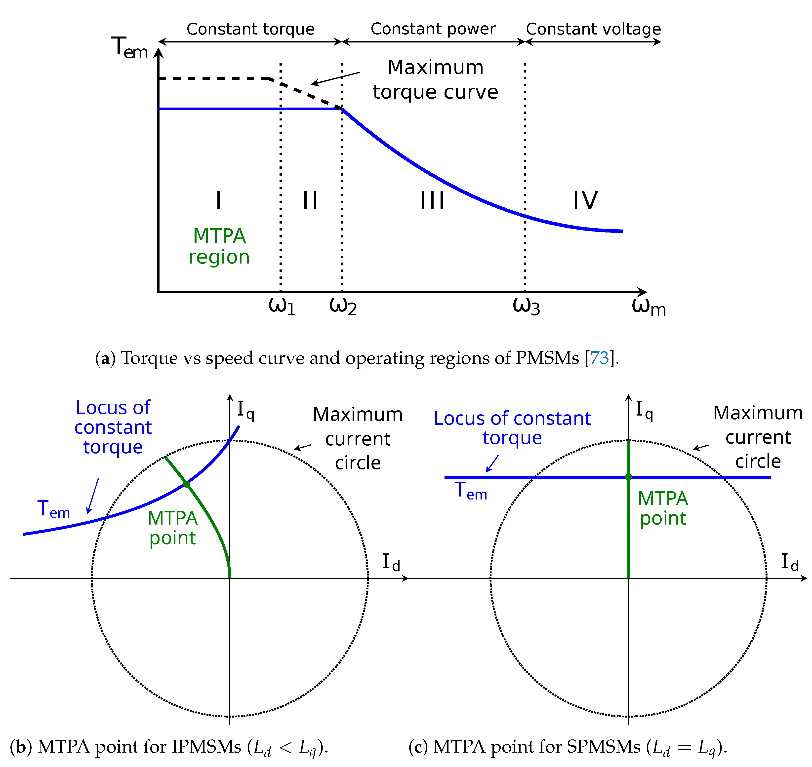
3.1. Operating Point in EVs: cos ϕ

Permanent magnet synchronous motors (PMSMs) are the most efficient and power-dense type of traction motors [71]. For this reason, this is the prevailing type of electrical machine for automotive traction [72]. Four operating regions are distinguished in this type on machines [73,74]: maximum torque per ampere (MTPA, Figure 6a—region I); field weakening region without and with torque reduction (Figure 6a—regions II and III, respectively); and maximum torque per volt (MTPV, Figure 6a—region IV). As MTPA operation of synchronous motors have become an indispensable part of highly efficient motor drives [75], this work is based in this operation region.
The electrical dynamic equations of PMSMs can be represented by using the rotating synchronous reference frame ( d q ), wherein the permanent magnetic flux is aligned with the d-axis, as
v d ( t ) = R s i d ( t ) + L d d i d ( t ) d t ω e ( t ) L q i q ( t ) ,
v q ( t ) = R s i q ( t ) + L q d i q ( t ) d t + ω e ( t ) L d i d ( t ) + Ψ P M ,
where v d and v q are the dq-axis time-dependent stator voltages, i d and i q are dq-axis time-dependent currents, L d and L q are the dq-axis inductances, R s is the stator resistance, Ψ P M is the permanent-magnet flux linkage, and ω e ( t ) = N p ω m ( t ) is the time-dependent electrical speed of the machine where ω m ( t ) is the time-dependent mechanical speed and N p is the number of pole pairs.
At steady-state conditions, (19a) and (19b) can be simplified as
V d = R s I d ω e L q I q ,
V q = R s I q + ω e L d I d + ω e Ψ P M ;
in addition, the electromagnetic torque at steady-state conditions is expressed as
T e m = 3 N p Ψ P M + L d L q I d I q .
It should be noted that (20) and (21) are described assuming that L d < L q , which is typical for interior PMSMs (IPMSMs). For surface-mounted PMSMs (SPMSMs), where L d = L q , the electromagnetic torque of (21) is only dependent on the q-current and can be simplified as
T e m = 3 N p Ψ P M I q .
Minimum copper losses and maximum torque per applied current modulus are guaranteed to track this MTPA region, which prevails at low speeds [75,76]. To perform a satisfactory torque control in PMSMs, the maximum torque per ampere (MTPA) point must be found.
The MTPA trajectory for three-phase IPMSMs is described in [76]. Following the same procedure for a six-phase IPMSMs, a fourth-order polynomial can be obtained in terms of I d
I d 4 + K 3 I d 3 + K 2 I d 2 + K 1 I d + K 0 = 0 ,
where,
K 0 = T e m 2 9 N p 2 ( L d L q ) 2 , K 1 = Ψ P M 3 ( L d L q ) 3 , K 2 = 3 Ψ P M 2 ( L d L q ) 2 , K 3 = 3 Ψ P M L d L q ;
solving (23), the d-current corresponding to the MTPA point is obtained, and then the q-current is calculated by using (21).
For SPMSMs, the MTPA point is always defined as I d = 0 , and I q is proportional to the electromagnetic torque; recall (22). Figure 6 depicts the MTPA trajectory for both IPMSMs and SPMSMs.
From the above, cos ϕ can be obtained considering the d q voltage equations of the machine (20) and the d q -currents corresponding to the MTPA curve. cos ϕ is expressed as cos ϕ = cos ϕ v cos ϕ i , where ϕ v is the angle corresponding to the d q voltages and ϕ i is the angle corresponding to the d q currents. These angles can be calculated as follows:
ϕ v = arctan V q / V d , for PMSMs ,
ϕ i = arctan I q / I d , for IPMSMs π / 2 , for SPMSMs .
To evaluate cos ϕ over standardized driving cycles, an IPMSM has been tested, the parameters of which are listed in Table 1. Figure 7 presents the speed and torque profiles in addition to the cos ϕ values corresponding to the worldwide harmonized light vehicles test procedure (WLTP) Class 3 and the new European driving cycle (NEDC) using this IPMSM. In order to make a fair comparison, torque and speed profiles are scaled according to the maximum and base values of the machine, which are shown in Table 1.
As Figure 7 shows, the value of cos ϕ over these standardized driving cycles is close to unity; more precisely, the average of cos ϕ > 0.97 over such cycles (Figure 7e,f). Therefore, cos ϕ = 1 will be assumed henceforth.

3.2. Input Current Harmonic Analysis for SPWM Technique

Figure 8 shows the high-frequency input current spectra for the SPWM technique, with M = 0.9 and cos ϕ = 1 . Specifically, Figure 8a depicts the input current of one branch of the inverter (i.e., i i n v 1 a ), Figure 8b shows it for the VSI1 ( i i n v 1 ), and Figure 8c for the whole ADTP inverter ( i i n v ). Applying the SPWM technique (in which v * * ( y ) = M cos ( y ) ) to (7), the input current spectrum of one branch of the inverter (i.e., i i n v 1 a ) can be expressed as
C m n i i n v 1 a = I ^ o u t m π cos m + n π 2 { cos ϕ × J n + 1 m M π 2 J n 1 m M π 2 + j sin ϕ × J n + 1 m M π 2 + J n 1 m M π 2 }
where J n + 1 ( m π 2 M ) and J n 1 ( m π 2 M ) are the Bessel functions of order n + 1 and n 1 with argument m π 2 M [77,78].
Equation (27) points out that the high-frequency carrier and sideband harmonics that exist in i i n v 1 a , and in turn in i i n v 1 (10) and i i n v (12), are those meeting that m + n is an even number (Figure 8). From (10), it is also inferred that the only harmonics that prevail at i i n v 1 are multiples of 3 ω 1 ( n = 3 k k Z ) (Figure 8b). In addition, from (12) it is inferred that the n = 6 2 k + 1 input current harmonics of i i n v 1 disappear from the input current spectrum of i i n v (Figure 8c). Regarding the carrier and sideband harmonics, the possible dominant harmonics for SPWM are assumed to exist among the pairs of ( m , n ) i.e., ( 1 , 3 ) , ( 1 , 3 ) , and ( 2 , 0 ) .
Inserting (27) into (12), the amplitudes of these harmonic components for i i n v result in
i i n v 1 , 3 = i i n v 1 , 3 = 3 2 I ^ o u t π × J 4 π 2 M J 2 π 2 M ,
i i n v 1 2 , 0 = 6 I ^ o u t 2 π × J 1 π M ,
because the values of J 2 and J 4 are similar, the amplitudes of i i n v 1 , 3 and i i n v 1 , 3 are almost neglectable compared to i i n v 2 , 0 . Therefore, the dominant harmonic component is i i n v 2 , 0 , i.e., the second-order switching harmonic, as can be confirmed in Figure 8c.

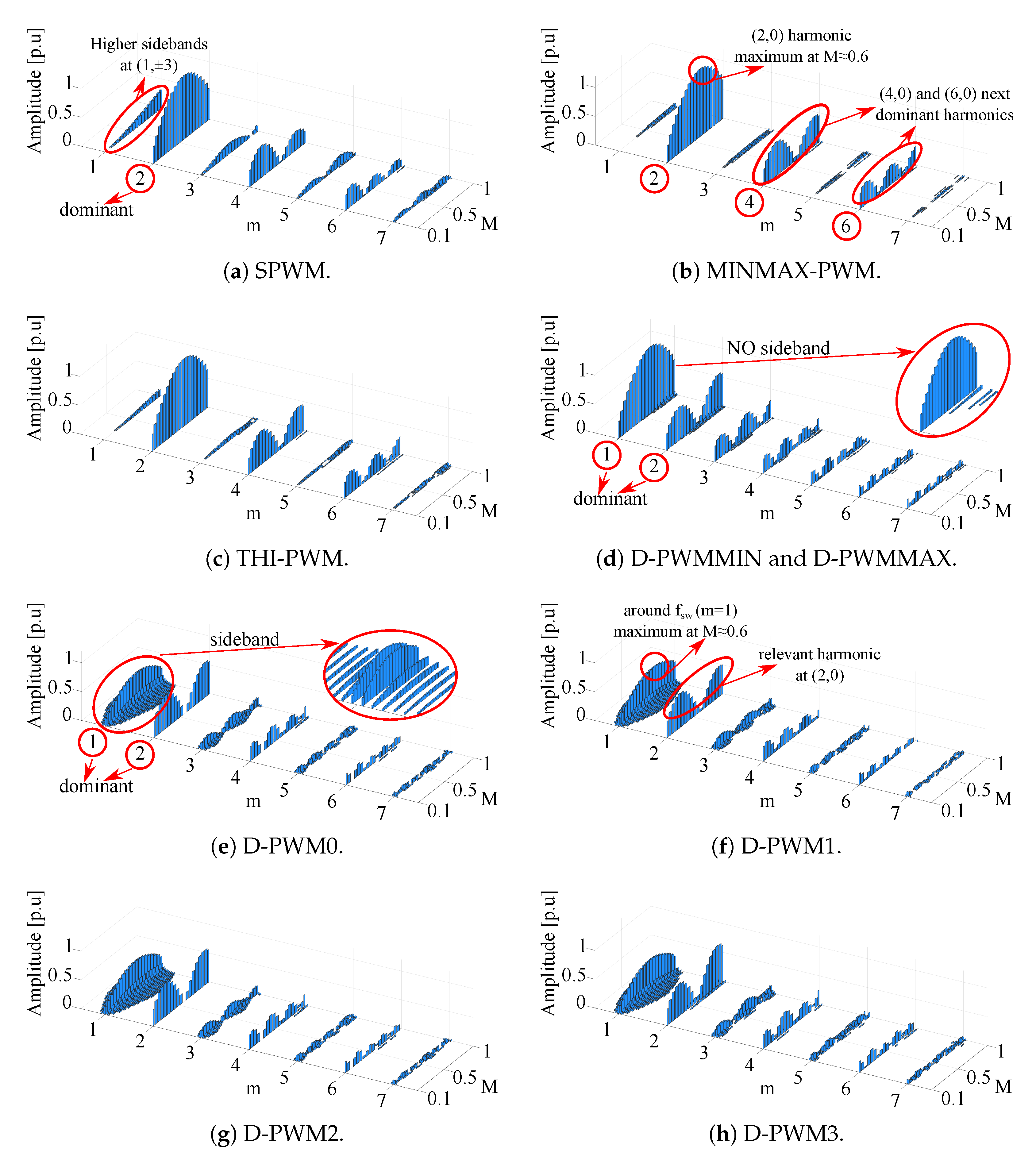
3.3. Input Current Harmonic Analysis for DZSI-PWM Techniques

The previous Fourier frequency-domain analysis makes it possible to obtain the normalized input current spectra ( i i n v , n o r m = i i n v / I ^ o u t ) of the ADTP inverter (Figure 1, i i n v ) for the DZSI-PWM techniques mentioned in Section 1 in addition to the SPWM technique. The current spectra for the above mentioned CB-PWM techniques have been checked by simulations on Matlab–Simulink R2020b in order to confirm that the previous Fourier double integral analysis (Section 2) is correct. The block diagram of the simulations carried out in Matlab–Simulink is represented in Figure 9. In order to match the results obtained by the analytical study on Matlab following the procedure of Section 2 (previously exposed in Figure 3), the same assumptions have been made: the output phase currents do not have any high-frequency ripple, and the DC-Link capacitor manages the whole ripple of the ADTP inverter current.
Figure 10 shows the current spectra of i i n v as a function of different vales of M, for the abovementioned CB-PWM techniques.
  • It highlights that for continuous modulations:
    • The predominant ( m , n ) harmonic component is ( 2 , 0 ) which corresponds to 2 f s w . This harmonic component has a maximum at M 0.6 .
    • The next dominant harmonics are situated at ( 4 , 0 ) and ( 6 , 0 ).
    • SPWM exhibits higher sideband harmonics at ( 1 , ± 3 ) than MINMAX-PWM and THI-PWM, which are quite similar in the full range of frequency and modulation index.
  • Regarding discontinuous modulations:
    • All analysed discontinuous PWM techniques have a significant harmonic component around f s w ( m = 1 ). This harmonic component has a maximum at M 0.6 .
    • D-PWM0, D-PWM1, D-PWM2, and D-PWM3 exhibit wide sideband harmonics around m = 1 , which leads to having harmonic components at lower frequencies, and the harmonics with highest amplitude are placed at ( 1 , ± 3 ) and ( 2 , 0 ).
    • D-PWMMAX and D-PWMMIN are equivalent, the sideband harmonics around m = 1 are not so relevant, the predominant component lies at ( 1 , 0 ), and the next important harmonic is placed at ( 2 , 0 ).
    • The relevant harmonic situated at ( 2 , 0 ) is negligible at M 0.6 .
The presence of harmonics influences the deterioration of the C D C . Therefore, it is desirable to reduce them as much as possible. For this purpose, the interleaving of the two three-phase inverters which form the ADTP multiphase VSI is detailed in the next section.

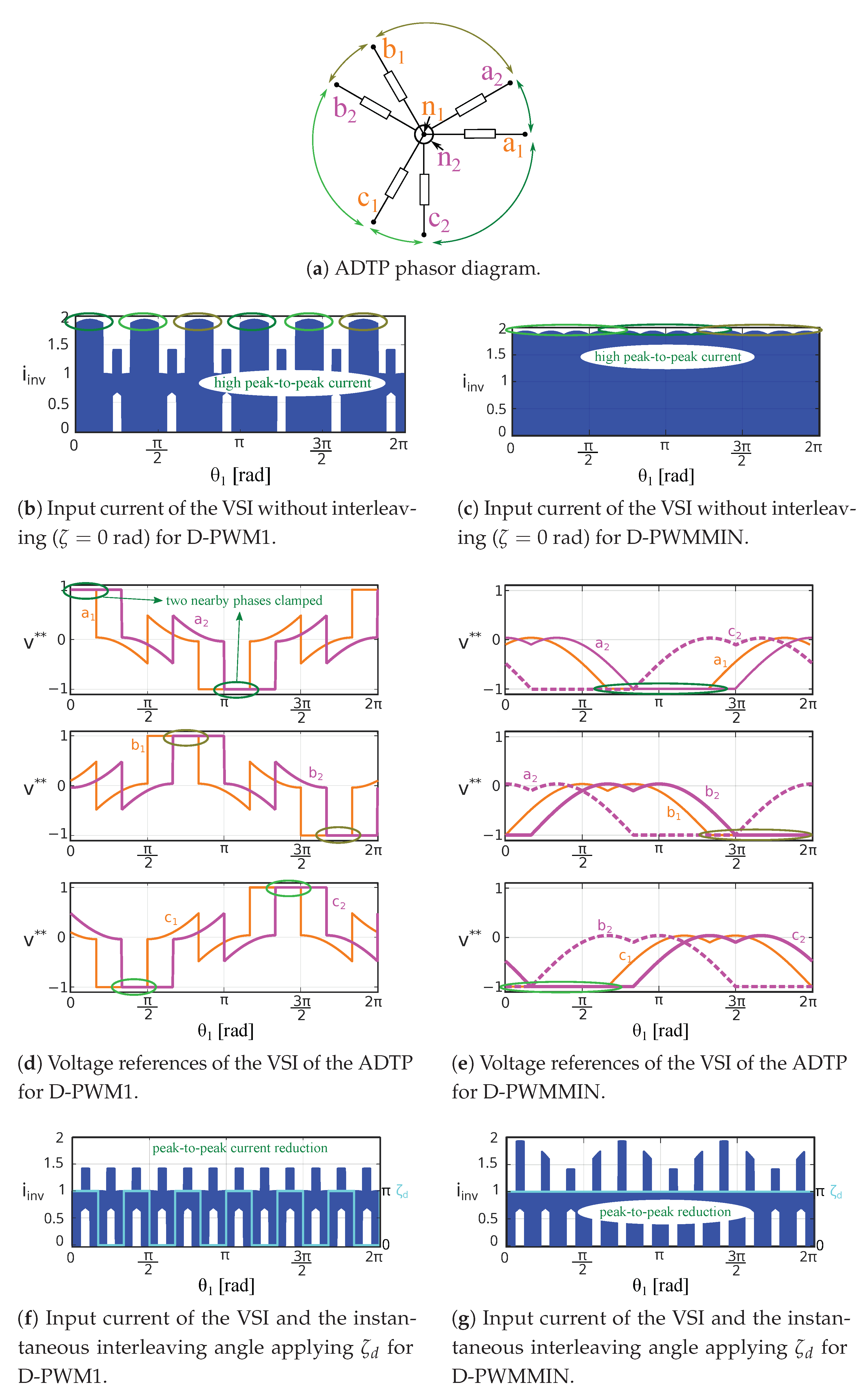
4. Interleaving Schemes to Improve the Performance of ADTP Inverters

Published works on ADTP interleaving [49,60,61,62] do not provide enough insight into the frequency-domain description of the input current. The rms value of rectangular current pulses depends on the amplitude I ^ o u t and the square root of the duty cycle ( I i n v 1 , r m s = D · I ^ o u t , Figure 11). When an interleaving angle ζ = 0 rad is applied between two inverters, the current pulses of both VSIs are totally overlapped, and the resulting pulses are doubled in amplitude, which leads to a double rms current value of the interleaved inverter current ( I i n v , r m s = 2 · D · I ^ o u t ). As the interleaving angle is increased, the overlap is reduced, and in turn, the rms value of the resulting waveform is reduced. When the interleaving angle between the pulses is large enough for them not to overlap ( ζ D ), the rms current is minimized ( I i n v , r m s = 2 · D · I ^ o u t ). This way, a reduction of the rms value is achieved with respect to the previous cases without interleaving (Figure 11).
In order to analyse the concept of interleaving in depth, three different schemes will be introduced: constant interleaving, dynamic interleaving, and optimal interleaving.

4.1. Constant Interleaving: ζ c

The concept of interleaving can be applied to the Fourier double series of the input current of the VSI2 by adding an additional phase shift with respect to the input current of the VSI1 (Figure 1). As Figure 11 shows, because x ( t ) is the variable related to the carrier wave angle, the Fourier coefficients for branch ‘a’ of the consecutive inverter ‘2’ ( C m n i i n v 2 a ) can be calculated by taking (7) and replacing m x with m ( x + ζ c ) . This can be also represented as
C m n i i n v 2 a = C m n i i n v 1 a · e j m ζ c ,
where e j m ζ c corresponds to the shifting caused by the interleaving of the second carrier signal ( v c r 2 , in Figure 11).
The introduction of this new parameter affects C m n i i n v 2 of (11) and C m n i i n v of (12), leading to
C m n i i n v 2 = C m n i i n v 1 a · 1 + 2 cos n 2 π 3 · e j n π 6 · e j m ζ c ,
C m n i i n v = C m n i i n v 1 a · 1 + 2 cos n 2 π 3 · 1 + e j n π 6 + m ζ c .
In (32), it can be observed that making the second term in brackets 1 + e j n π 6 + m ζ c equal to 0, an interleaving angle ζ c that cancels some specific input current harmonics ( C m n i i n v , (12)) is obtained:
ζ c = 2 k + 1 · π n π 6 m k Z + .
In this sense, and because the dominant harmonic is the most important component when it comes to computing the rms value of the whole current spectrum through the capacitor, the interleaving angle ( ζ c ) should eliminate this dominant harmonic. Table 2 summarizes the most significant constant interleaving angles and the harmonic orders cancelled. This table also points out when the most relevant input current harmonics are removed: letting ζ c = π / 2 rad erases the ( 2 , 0 ) and ( 1 , 3 ) harmonics, whereas letting ζ c = π rad erases the ( 1 , 0 ) harmonic.
As a collateral effect, sometimes other harmonics can slightly increase their amplitude. Therefore, the angle which eliminates the dominant input current harmonic and the one which minimizes I c a p , r m s can be different. For example, Figure 12 shows the input current spectrum for the ADTP with SPWM technique, M = 0.9 , cos ϕ = 1 and two interleaving angles ( ζ c = 0 rad and ζ c = π / 2 rad). For this case, it can be observed that the dominant harmonic ( 2 , 0 ) has been cancelled out, but ( 1 , 3 ) and ( 2 , ± 6 ) have increased their amplitude. Therefore, the selection of the interleaving angle has to be made carefully.
In view of this, numerical calculations have been carried out in Matlab following the procedure explained in Section 2 for each DZSI-PWM technique, by sweeping the modulation index M and the interleaving angle ζ c . All these calculations show that the ζ c = π / 2 rad constant angle minimizes I c a p , r m s regardless of the value of M for all the analysed DZSI-PWM techniques except for D-PWMMIN and D-PWMMAX, in which ζ c = π rad is the best choice for any value of M. However, from the numerical analysis carried out, it has been seen that the constant angle applied for the entire period of the fundamental of D-PWMMIN and D-PWMMAX ζ c = π is the best option only for M 0.75 ; and for M > 0.75 the interleaving angle which minimizes the I c a p , r m s is only constant for each fundamental period but not for rest of the linear range. This is explained better in Section 4.3. This analysis coincides with the above performed input harmonic spectra of Figure 10, as well as with the removal of the dominant harmonics observed in Table 2.
Finally, as an example of this analysis, Figure 13 shows the case of the SPWM technique. Here, note that for M = 0.35 (Figure 13a), I c a p , r m s is at minimum when ζ c lies between 1.08 and 2.06 rad even though the current spectra is not the same (Figure 13c–e. Performing the same analysis in the whole linear region of M, for 0 M < 0.5 , there is not a single ζ c which minimizes I c a p , r m s but a range of values (Figure 13b); however, for 0.5 M 1 there is just one ζ c value ( π / 2 rad) that is considered the best choice ζ c in the entire range of M for the SPWM technique.

4.2. Dynamic Interleaving Scheme for Discontinuous PWM Techniques: ζ d

Unlike the constant interleaving scheme discussed above, a dynamic interleaving algorithm ζ d applicable only for discontinuous PWM has been recently proposed in [63] to reduce the DC-Link current ripple of the ADTP. In this case, the interleaving angle of the proposed method is not constant. In some subintervals of the fundamental period cycle, ζ is set to π rad whereas the rest of the time it is 0 rad.
In any discontinuous PWM technique, the peak-to-peak value of the input current of the VSI without any interleaving rises significantly when any two nearby phases (Figure 14a) in the phasor diagram are clamped to ± 1 . As an example, Figure 14 shows the operation basics of ζ d for D-PWM1 and D-PWMMIN. Figure 14b,c show the input current of the VSI without interleaving ( ζ = 0 rad) for these discontinuous PWM techniques and Figure 14d,e their respective voltage references of the ADTP.
In the case of D-PWMMIN, two nearby phases in the phasor diagram are continuously clamped to ± 1 (Figure 14e). This leads to a continuous activation of the dynamic interleaving algorithm (Figure 14g, ζ d in blue). This means that for this specific PWM technique, the dynamic interleaving scheme is exactly the same as applying a constant angle of ζ c = π rad. The effect of applying this angle can be visualized in Figure 14f,g for D-PWM1 and D-PWMMIN, respectively. The peak-to-peak values of the input currents are reduced significantly comparing to the ζ = 0 rad scenario of Figure 14b,c. The techniques D-PWM0, D-PWM2 and D-PWM3 follow the same pattern as D-PWM1, whereas D-PWMMAX behaves as D-PWMMIN in terms of full-time clamping. Therefore, for both D-PWMMIN and D-PWMMAX, applying the dynamic interleaving scheme would be exactly like applying the scheme ζ c = π rad explained in the previous subsection.
As a counterpart, this dynamic interleaving scheme ( ζ d ) has some disadvantages compared to the constant interleaving ( ζ c ); i.e., more computational resources are needed in order to detect the voltage reference clampings between two nearby phases in the phasor diagram; in addition, it is only applicable for discontinuous PWM techniques.

4.3. Optimal Interleaving Scheme for any DZSI-PWM: ζ o p t

The optimal interleaving scheme ( ζ o p t ) can be defined as the one which minimizes I c a p , r m s over the entire linear region, 0 M 1 . In the case of continuous techniques, ζ o p t = ζ c because a dynamic interleaving scheme cannot be used. Therefore, the optimal interleaving angle can be considered ζ c = π / 2 rad.
In the case of the D-PWMMIN and D-PWMMAX techniques, it is a bit more complex. First, it is worth remembering that as the dynamic interleaving is applied continuously, it is the same as applying a constant interleaving of ζ c = π rad. In addition, following the numerical analysis described in Section 4.1 and as Figure 15 shows, ζ = π rad minimizes I c a p , r m s for 0 M 1 . However, for higher modulation indexes, the interleaving angle becomes smaller. This happens because in this range of M, although the ( 1 , 0 ) harmonic is not completely cancelled, the harmonics that have great influence on the rms value of the current, such as ( 1 , 0 ) and ( 2 , 0 ), are considerably attenuated.
Finally, for the rest of discontinuous techniques (D-PWM0, D-PWM1, D-PWM2 and D-PWM3), the optimal interleaving scheme consists of comparing both interleaving algorithms and selecting the one which gives the smallest I c a p , r m s for each modulation index.
Therefore, the implementation of this optimal interleaving scheme is performed following the indications in Figure 16. The next section will show the results obtained for all the interleaving schemes.

5. Influence of Interleaving for DZSI-PWM Techniques on the Current Ripple and Voltage in the DC-Link Capacitor

The influence of DZSI-PWM techniques on I c a p , r m s and Δ v p p , m a x has been identified through the interleaving schemes described in Section 4 as a function of M and for cos ϕ = 1 by using the methodology described in Figure 3.
In contrast to three-phase VSIs, where the rms current through the DC-Link capacitor is independent of the chosen PWM technique [67], in the ADTP with double zero sequence injection technique it is strongly dependent on it. This happens due to the 30° shifting between the two three-phase inverters forming the ADTP. The rms value of the input current of either the first inverter or the second inverter do not depend on the modulation technique but their sum does:
I i n v , r m s I i n v 1 , r m s + I i n v 2 , r m s .
In general terms, in EV applications, the DC-Link capacitor is selected mainly considering the ripple current through the capacitor. As there are no low-frequency harmonic components as in single-phase converters, the voltage ripple is lower for a multiphase application with the same power rating. For this reason, the optimal interleaving angle must be selected based on the current profile and not on the basis of the voltage ripple. However, in any case, it is also interesting to analyse whether this optimal interleaving scheme which minimizes I c a p , r m s also reduces Δ v p p , m a x . The I c a p , r m s results shown in the following section were obtained by using the double Fourier integral analysis of Section 2 and the results that correspond to Δ v p p , m a x were obtained by a numerical analysis in Matlab–Simulink. Finally, in Section 5.3 I c a p , r m s is simulated for EV dynamic conditions applying the WLTP driving cycle.

5.1. RMS Value of the Current through DC-Link Capacitor at Static Operating Points

Figure 17 shows the rms current curves for the different DZSI-PWM techniques. Here, it can be observed that without using interleaving algorithm (in blue) D-PWM1, D-PWM0, D-PWM2, and D-PWM3 present the lowest I c a p , r m s (in that order) and continuous techniques, as well as D-PWMMIN and D-PWMMAX have the highest values of I c a p , r m s . Although the differences between these two main PWM groups are bigger for central values of M ( 0.4 < M < 0.7 ), when M gets close to 1 ( M > 0.9 ), all analysed PWM techniques tend to equalise. These continuous PWM techniques, as well as D-PWMMIN and D-PWMMAX, present a maximum value at M 0.6 .
When the proposed optimal interleaving scheme is applied (Figure 17, in black), continuous modulations with ζ o p t = π / 2 rad reduce I c a p , r m s of up to 62% for SPWM, 84% for MINMAX-PWM and 80% for THI-PWM. For discontinuous modulations, reductions up to 80% for D-PWMMIN and D-PWMMAX and 78% for D-PWM0, D-PWM1, D-PWM2 and D-PWM3 are obtained. D-PWM1 and MINMAX-PWM provides the lowest values of I c a p , r m s (in that order).

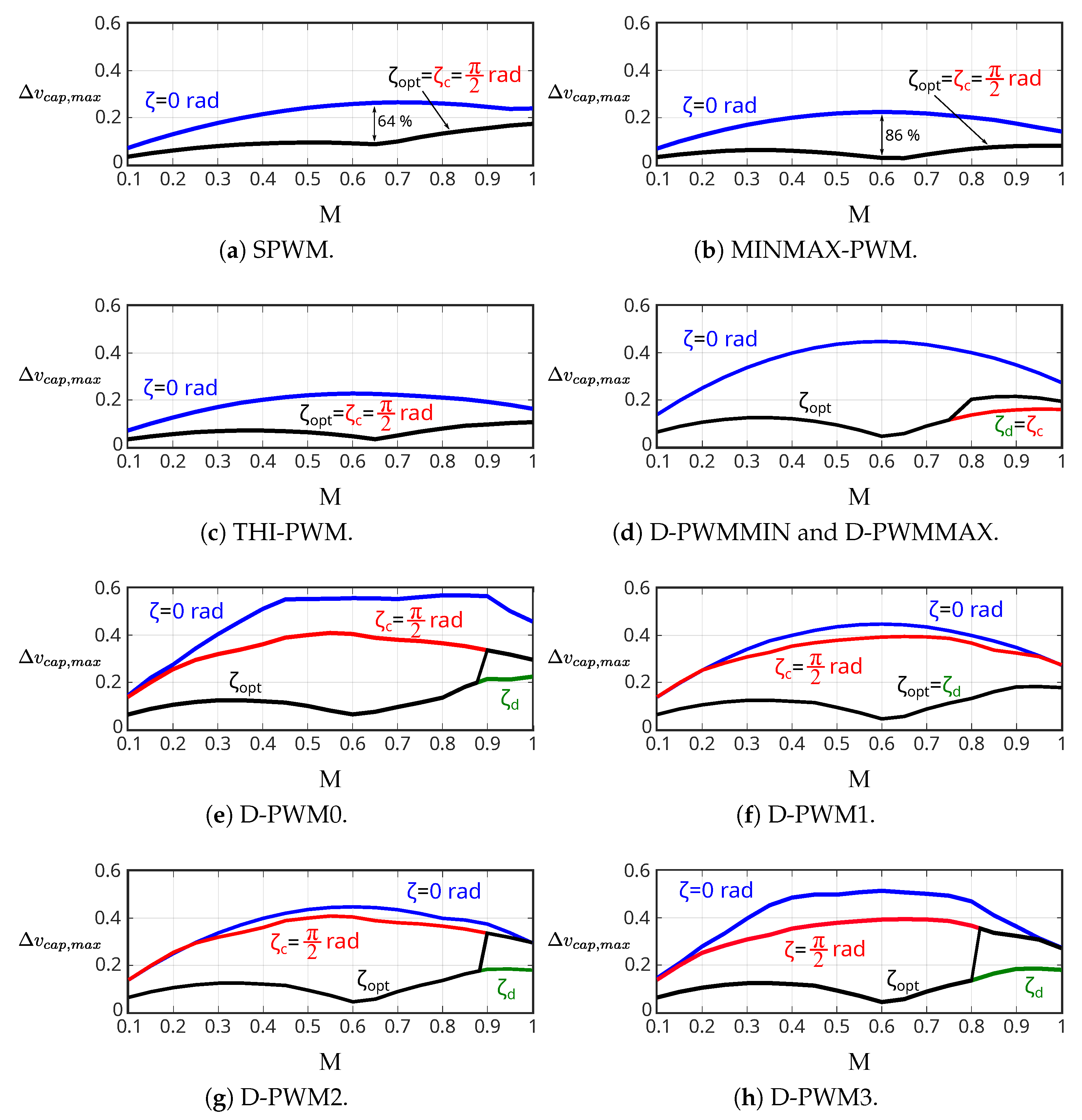
5.2. Voltage Ripple in the DC-Link Capacitor at Static Operating Points

Even though the main idea of the interleaving approach is to reduce the rms value of the current through the DC-Link capacitor, Figure 18 shows that it also reduces the DC-Link voltage ripple ( Δ v c a p , m a x ) for all DZSI-PWMs.
Unlike the rms value of the current through the DC-Link capacitor, when no interleaving ( ζ = 0 rad) is applied, continuous PWM techniques (MINMAX-PWM, THI-PWM and SPWM, in that order) present the lowest Δ v p p , m a x , and discontinuous techniques present the highest values of Δ v c a p , m a x (Figure 18). Specifically, MINMAX-PWM provides the smallest and D-PWM0 provides the highest voltage ripple among these noninterleaved DZSI-PWM techniques.
When the proposed optimal interleaving scheme ( ζ = ζ o p t ) is applied, the following maximum reductions of Δ v p p , m a x are obtained: up to 64% for SPWM, 86% for MINMAX-PWM, 85% for THI-PWM, 90% for D-PWMMIN and D-PWMMAX, 88% for D-PWM0, 90% for D-PWM1, 90% for D-PWM2, and 91% for D-PWM3. The DZSI-PWM technique which presents the smallest Δ v p p , m a x once the optimal interleaving scheme is applied is MINMAX-PWM.
As has been seen in this section, the combination of the optimal interleaving scheme and DZSI-PWM techniques is a good alternative in order to reduce the stress variables on the DC-Link capacitors of the ADTP power converters for electric vehicles. However, it is enough to apply a constant interleaving scheme ( ζ c ) in order to reduce the current stress on the DC-Link capacitor considerably.

5.3. RMS Value of the Current through DC-Link Capacitor during Standardized Driving Cycles

Figure 19 shows the block diagram of the ADTP platform and the simulation model used to obtain the results during EV dynamic conditions. The vehicle battery has been modelled as a 400 V DC source according to the typical values of electric vehicles [43]. The selected DC-Link capacitance has been 600 μF. The motor that has been modelled is the one indicated in Table 1 (Section 3.1). A maximum motor current of 25 A has been set and the base mechanical speed of the motor has been changed to 2400 rpm. Lastly, the control algorithm used is explained in detail in [79] and the switching frequency of the power devices has been set to 25 kHz.
Matlab–Simulink has been used to execute the simulation models, and they have been embedded on an OPAL-RT OP4510 high-performance, real-time platform, which has accelerated the simulation time considerably. The simulation step has been set to 1 μs. In addition, in order to visualize in a more didactic way and compare of the results with and without interleaving, the results have been postprocessed with a moving average of 2000 samples.
Figure 20 shows the results of I c a p , r m s in the whole WLTP driving cycle, with and without constant interleaving angle for each DZSI-PWM technique ( ζ c = π / 2 rad for the techniques SPWM, MINMAX-PWM, THI-PWM, D-PWM0, D-PWM1, D-PWM2, D-PWM3; and ζ c = π rad for D-PWMIN and D-PWMMAX). Here, it can be observed that all the analysed PWM techniques reduce I c a p , r m s when the interleaving scheme is applied. Likewise, Table 3 shows the mean value of the rms current throughout the entire WLTP driving cycle. These results confirm that an adequate constant interleaving scheme reduces the current stress on the DC-Link capacitor considerably. These simulations show that reductions up to 26% can be achieved. The largest reductions are provided by continuous PWM techniques, and the lowest values of I c a p , r m s are found for discontinuous PWM techniques. However, these D-PWMs are not so often used in EV application because they worsen the quality of the output voltage waveform.

6. Conclusions

The ADTP has turned out to be one of the most successful multiphase arrangement in the short term for electric traction applications due to its intrinsic advantages, such as enhanced efficiency and fault-tolerant operation. In power converters in general, and therefore also in ADTP architecture, the DC-Link capacitor is a critical element that represents a considerable fraction of the volume and source of failures because it is responsible for up to a 40% of the total volume and 30% of the total failures in power electronic inverters.
This work focuses on the DC-Link stress reduction in order to benefit this capacitors by means of the following figures of merit: rms value of the ripple current through the DC-Link capacitor ( I c a p , r m s ) and the maximum peak-to-peak voltage ripple ( Δ v c a p , m a x ). For that purpose, the input current spectra of the ADTP arrangement have been analysed by using the double Fourier integral method for the DZSI-PWM techniques. Although each branch of the multiphase VSI presents certain input current harmonics, the interaction between the different branches inherent to the ADTP architecture cancels them out and changes the amplitude of some of these harmonics.
All these input current harmonics depend mainly on the selected DZSI-PWM technique, as well as on M and cos ϕ . For electric vehicle applications, the main vehicle standard driving cycles NEDC and WLTP using a PMSM demonstrate that the value of the power factor is cos ϕ > 0.97 . Thus, the current spectra for these DZSI-PWM techniques have been obtained as a function of M and for cos ϕ = 1 . Here, it has been observed that continuous PWM techniques (SPWM, MINMAX-PWM, and THI-PWM) have a predominant carrier wave harmonics at 2 f s w ; D-PWM0, D-PWM1, D-PWM2, and D-PWM3 have a wide sideband harmonic range around f s w , even though their carrier wave harmonics at 2 f s w cannot be neglected; finally, D-PWMMIN and D-PWMMAX have their predominant current harmonics at f s w and 2 f s w .
Due to lack of in-depth research in the scientific literature about the interleaving schemes for this kind of ADTP arrangements, this work has analytically derived the relationship between the input current harmonic spectrum and the constant interleaving angle ( ζ c ), as well as how this can be exploited in order to cancel certain dominant harmonics inherent to these DZSI-PWM techniques. As a result, the rms value of the ripple current through the DC-Link capacitor ( I c a p , r m s ) and the maximum peak-to-peak voltage ripple ( Δ v c a p , m a x ) has been reduced. This confirms that the elimination of the dominant input current harmonics is directly related to the minimization of I c a p , r m s .
It has been concluded that for all continuous PWM techniques the optimal interleaving angle is ζ c = π / 2 rad because it eliminates the dominant carrier harmonic at 2 f s w . For discontinuous PWMs, a combination between the dynamic (only applicable for discontinuous PWM techniques) and the constant interleaving schemes is generally preferred. During the subinterval in which the constant interleaving scheme is applied, for D-PWM0, D-PWM1, D-PWM2, and D-PWM3 ζ c = π / 2 rad is preferred because their 2 f s w carrier wave harmonic and f s w + 3 f 1 sideband harmonic are cancelled out. However, for D-PWMMIN and D-PWMMAX, ζ c π rad is preferred because it eliminates or attenuates the f s w dominant input current harmonic.
All the analysed PWM techniques have been shown to improve significantly their characteristics compared to conventional noninterleaved operation. In general, the major DC-Link stress reductions are obtained for continuous PWM techniques throughout the linear range with the same constant interleaving angle. More specifically, the largest reductions are obtained with MINMAX-PWM where I c a p , r m s is reduced up to 84% and Δ v c a p , m a x up to 86%.
These results favour continuous over discontinuous PWM techniques. These are the most widely used in electric vehicle propulsion systems. In addition, it must be considered that discontinuous modulation techniques have the intrinsic disadvantage of producing worse harmonic distortion in the load than continuous modulation techniques. Moreover, some of these techniques, such as D-PWM0 and D-PWM2, are mostly focused on more capacitive than inductive loads. All of these considerations lead the automotive industry to use continuous techniques. Finally, it can be said that the work carried out in this document allows the reader to identify the adequate interleaving angle both to reduce the stress of the DC-Link capacitor, and in general terms, to make electric vehicle propulsion systems more reliable.

Author Contributions

Conceptualization, A.D., E.R., U.U., I.M.d.A. and J.A.; methodology, A.D., E.R. and U.U.; software, A.D. and J.A.; validation, A.D., E.R, U.U., I.M.d.A. and J.A.; formal analysis, A.D and U.U.; investigation, A.D., E.R., U.U., I.M.d.A. and J.A.; resources, J.A. and I.M.d.A.; data curation, E.R. and U.U.; writing—original draft preparation, A.D., E.R., U.U., I.M.d.A. and J.A.; writing—review and editing, A.D., E.R., U.U., I.M.d.A. and J.A.; visualization, E.R.; supervision, U.U. and J.A.; project administration, I.M.d.A. and J.A.; funding acquisition, I.M.d.A. and J.A. All authors have read and agreed to the published version of the manuscript.

Funding

This work was supported in part by the Government of the Basque Country within the fund for research groups of the Basque University system IT1440-22 and by the MCIN/AEI/10.13039/501100011033 within the project PID2020-115126RB-I00, as well as the support of the UPV/EHU pre-doctoral programme (PIF20-305).

Institutional Review Board Statement

Not applicable.

Informed Consent Statement

Not applicable.

Data Availability Statement

Not applicable.

Acknowledgments

Applied Electronics Research Team (APERT) UPV/EHU.

Conflicts of Interest

Not applicable.

List of Abbreviations

The following abbreviations are used in this manuscript:
ADTPAsymmetrical Dual Three-Phase
CBCarrier-Based
C-PWMContinuous PWM
DCDirect Current
DOEUnited States Department of Energy
D-PWMDiscontinuous PWM
DZSIDouble Zero Sequence Injection
ESREquivalent Series Resistance
EVElectric Vehicle
HDFHarmonic Distortion Factor
IPMSMInterior Permanent Magnet Synchronous Motor
MINMAX-PWMMIN-MAX PWM method
MTPAMaximum Torque Per Ampere
MTPVMaximum Torque Per Volt
NEDCNew European Driving Cycle
PMPermanent Magnet
PMSMPermanent Magnet Synchronous Motor
PWMPulse-Width Modulation
SPWMSinusoidal PWM
SPMSMSurface-mounted Permanent Magnet Synchronous Motor
SVSpace Vector
THDTotal Harmonic Distortion
THI-PWMThird Harmonic Injection PWM
UN ESCAPUnited Nations’ Economic and Social Commission for Asia and the Pacific
USCARThe United States Council for Automotive Research
VSIVoltage-Source Inverters
WBGWide BandGap
WLTPWorldwide Harmonized Light vehicles Test Procedure

List of Symbols

The list of symbols with respective units, if applicable, used in this manuscript is the following:
A m n , B m n Real and imaginary coefficients of a Double Fourier series expansion.
C m n Complex-valued Double Fourier coefficient, C m n = A m n + j B m n .
C m n i n v 1 a C m n i n v 2 c Complex-valued Double Fourier coefficients of i i n v 1 a i i n v 2 c (A).
C D C DC-Link capacitance (F).
DDuty cycle.
ESREquivalent Series Resistance of capacitor ( Ω ).
f 1 Fundamental frequency of modulating signal (Hz).
f h Harmonic frequency values, f h = n f 1 + m f s w (Hz).
f s w Frequency of carrier signal (Hz).
gGeneric two-variable time-domain function, g x t , y t .
i d , i q Direct-, quadrature-axis currents of PMSM (A).
I d , I q Steady-state values of i d , i q (A).
i 1 a i 2 c Current flowing into loads a c of each VSI (A).
i i n v 1 a i i n v 2 c Current flowing into legs a c of VSI1, VSI2 (A).
i i n v 1 , i i n v 2 Total current flowing into each VSI1, VSI2 (A).
I b a t Current coming from upstream DC source, I b a t = I i n v , a v g (A).
i c a p ; I c a p , r m s Current flowing into capacitor, i c a p = i i n v , A C ; its rms value (A).
i i n v ; i i n v , A C Total current flowing into both VSIs; its ripple component (A).
I i n v , a v g ; I i n v , r m s Average of i i n v ; rms of i i n v , A C (A).
I ^ o u t Amplitude of output phase currents (A).
J k · Bessel function of the first kind and order k.
K 0 K 3 Parameters to tune the MTPA control strategy.
L d , L q Direct-, quadrature-axis inductances of PMSM model (H).
MModulation index, M = V ^ 1 / V D C 2 .
N p Number of pole pairs of PMSM.
n , m Baseband and carrier index variables, respectively.
R S Stator resistance of PMSM model ( Ω ).
T 1 Fundamental period, T 1 = 1 f 1 (s).
T e m Electromagnetic torque produced by PMSM (Nm).
T m a x Maximum torque specification of the PMSM (Nm).
T s w Switching period, T s w = 1 f s w (s).
v 0 s Injected zero-sequence component.
v c r Carrier signal (triangle-shaped).
v * Modulating signal, v * = M cos θ 1 .
v * * Modified modulating signal, v * * = v * + v 0 s .
v d , v q Direct-, quadrature-axis voltages of PMSM (V).
V d , V q Steady-state values of v d , v q (V).
V ^ 1 Peak value of phase-to-neutral voltage (V).
V D C DC-link voltage (V).
x t , y t Intermediate time-domain variables, x t = ω s w t , y t = ω 1 t .
x r , x f Integration limits for x t .
Δ v c a p Capacitor ripple voltage (V).
Δ v c a p , m a x Maximum Δ v c a p , p p over T 1 (V).
Δ v c a p , p p Peak-to-peak value of the DC-Link voltage ripple in T s w (V).
ζ , ζ c , ζ d , ζ o p t Interleaving angle: generic, constant, dynamic, optimal.
θ 1 Angular position of modulating signal, θ 1 = ω 1 t .
Φ v , Φ i Partial phase lags given by V q / V d , I q / I r ratios (or equalling π / 2 ).
ϕ Lag with respect to θ 1 of current flowing into load ‘a’ of VSI1.
Ψ P M Permanent-magnet flux in PMSM model (Wb).
ω 1 Fundamental angular frequency of modulating signal ( s 1 ).
ω e Electrical speed of PMSM ( s 1 ).
ω m Mechanical speed of PMSM ( s 1 ).
ω s w Angular frequency of carrier signal ( s 1 ).

References

  1. 2021 Electrification Annual Progress Report; Technical Report 20585; Vehicle Technologies Office—Department of Energy (DOE): Washington, DC, USA, 2022.
  2. Levi, E. Advances in Converter Control and Innovative Exploitation of Additional Degrees of Freedom for Multiphase Machines. IEEE Trans. Ind. Electron. 2016, 63, 433–448. [Google Scholar] [CrossRef]
  3. Munim, W.N.W.A.; Duran, M.J.; Che, H.S.; Bermúdez, M.; González-Prieto, I.; Rahim, N.A. A Unified Analysis of the Fault Tolerance Capability in Six-Phase Induction Motor Drives. IEEE Trans. Power Electron. 2017, 32, 7824–7836. [Google Scholar] [CrossRef]
  4. Wang, X.; Wang, Z.; Xu, Z.; Cheng, M.; Wang, W.; Hu, Y. Comprehensive Diagnosis and Tolerance Strategies for Electrical Faults and Sensor Faults in Dual Three-Phase PMSM Drives. IEEE Trans. Power Electron. 2019, 34, 6669–6684. [Google Scholar] [CrossRef]
  5. Feng, G.; Lai, C.; Kelly, M.; Kar, N.C. Dual Three-Phase PMSM Torque Modeling and Maximum Torque per Peak Current Control Through Optimized Harmonic Current Injection. IEEE Trans. Ind. Electron. 2019, 66, 3356–3368. [Google Scholar] [CrossRef]
  6. Wang, W.; Zhang, J.; Cheng, M.; Li, S. Fault-tolerant control of dual three-phase permanent-magnet synchronous machine drives under open-phase faults. IEEE Trans. Power Electron. 2017, 32, 2052–2063. [Google Scholar] [CrossRef]
  7. Eldeeb, H.M.; Abdel-Khalik, A.S.; Kullick, J.; Hackl, C. Pre- and postfault current control of dual three-phase reluctance synchronous drives. IEEE Trans. Ind. Electron. 2020, 67, 3361–3373. [Google Scholar] [CrossRef]
  8. Xiao, L.; Zhang, L.; Gao, F.; Quian, J. Robust fault-tolerant synergetic control for dual three-phase PMSM drives considering speed sensor fault. IEEE Access 2020, 8, 78912–78922. [Google Scholar] [CrossRef]
  9. Teymoori, V.; Kamper, M.; Wang, R.J.; Kennel, R. Sensorless control of dual three-phase permanent magnet synchronous machines—A review. Energies 2023, 16, 1326. [Google Scholar] [CrossRef]
  10. Frikha, M.A.; Croonen, J.; Deepak, K.; Benômar, Y.; El Baghdadi, M.; Hegazy, O. Multiphase motors and drive systems for electric vehicle powertrains: State of the art analysis and future trends. Energies 2023, 16, 768. [Google Scholar] [CrossRef]
  11. Robles, E.; Fernandez, M.; Andreu, J.; Ibarra, E.; Zaragoza, J.; Ugalde, U. Common-mode voltage mitigation in multiphase electric motor drive systems. Renew. Sustain. Energy Rev. 2022, 157, 1–21. [Google Scholar] [CrossRef]
  12. Zhu, Z.; Wang, S.; Shao, B.; Yan, L.; Xu, P.; Ren, Y. Advances in Dual-Three-Phase Permanent Magnet Synchronous Machines and Control Techniques. Energies 2021, 14, 7508. [Google Scholar] [CrossRef]
  13. Karttunen, J.; Kallio, S.; Peltoniemi, P.; Silventoinen, P.; Phyronen, O. Decoupled vector control scheme for dual three-phase permanent magnet synchronous machines. IEEE Trans. Ind. Electron. 2014, 61, 2185–2196. [Google Scholar] [CrossRef]
  14. Miyama, Y.; Ishizuka, M.; Kometani, H.; Akatsu, K. Vibration reduction by applying carrier phase-shift PWM on dual three-phase winding permanent magnet synchronous motor. IEEE Trans. Ind. Appl. 2018, 54, 5998–6004. [Google Scholar] [CrossRef]
  15. Hu, Y.; Huang, S.; Wu, X.; Li, X. Control of dual three-phase permanent magnet synchronous machine based on five-leg inverter. IEEE Trans. Power Electron. 2019, 34, 11071–11079. [Google Scholar] [CrossRef]
  16. Barcaro, M.; Bianchi, N.; Magnussen, F. Analysis and Tests of a Dual Three-Phase 12-Slot 10-Pole Permanent-Magnet Motor. IEEE Trans. Ind. Appl. 2010, 46, 2355–2362. [Google Scholar] [CrossRef]
  17. Shen, Z.; Jiang, D.; Liu, Z.; Ye, D.; Li, J. Common-mode voltage elimination for dual two-level inverter-fed asymmetrical six-phase PMSM. IEEE Trans. Power Electron. 2020, 35, 3828–3840. [Google Scholar] [CrossRef]
  18. Nelson, R.H.; Krause, P.C. Induction Machine Analysis for Arbitrary Displacement Between Multiple Winding Sets. IEEE Trans. Power Appar. Syst. 1974, PAS-93, 841–848. [Google Scholar] [CrossRef]
  19. Fernandez, M.; Sierra-Gonzalez, A.; Robles, E.; Kortabarria, I.; Ibarra, E.; Martin, J.L. New Modulation Technique to Mitigate Common Mode Voltage Effects in Star-Connected Five-Phase AC Drives. Energies 2020, 13, 607. [Google Scholar] [CrossRef]
  20. Zhao, Y.; Lipo, T. Space vector PWM control of dual three-phase induction machine using vector space decomposition. IEEE Trans. Ind. Appl. 1995, 31, 1100–1109. [Google Scholar] [CrossRef]
  21. Hadiouche, D.; Baghli, L.; Rezzoug, A. Space-vector PWM techniques for dual three-phase AC machine: Analysis, performance evaluation, and DSP implementation. IEEE Trans. Ind. Appl. 2006, 42, 1112–1122. [Google Scholar] [CrossRef]
  22. Marouani, K.; Baghli, L.; Hadiouche, D.; Kheloui, A.; Rezzoug, A. A New PWM Strategy Based on a 24-Sector Vector Space Decomposition for a Six-Phase VSI-Fed Dual Stator Induction Motor. IEEE Trans. Ind. Electron. 2008, 55, 1910–1920. [Google Scholar] [CrossRef]
  23. Prieto, J.; Riveros, J.A.; Bogado, B. Continuous and discontinuous SVPWM 2L+2M for asymmetrical dual three-phase drives. In Proceedings of the IEEE International Electric Machines and Drives Conference (IEMDC), Miami, FL, USA, 21–24 May 2017; pp. 1–6. [Google Scholar]
  24. Suhel, S.M.; Maurya, R. Realization of 24-Sector SVPWM With New Switching Pattern for Six-Phase Induction Motor Drive. IEEE Trans. Power Electron. 2019, 34, 5079–5092. [Google Scholar] [CrossRef]
  25. Bojoi, R.; Tenconi, A.; Profumo, F.; Griva, G.; Martinello, D. Complete analysis and comparative study of digital modulation techniques for dual three-phase AC motor drives. In Proceedings of the IEEE Power Electronics Specialists Conference (PESC), Cairns, Australia, 23–27 June 2002; pp. 851–857. [Google Scholar]
  26. Rakesh, P.; Narayanan, G. Analysis of sine-triangle and zero-sequence injection modulation schemes for split-phase induction motor drive. IET Power Electron. 2016, 9, 1–12. [Google Scholar] [CrossRef]
  27. Prieto, J.; Levi, E.; Barrero, F.; Toral, S. Output current ripple analysis for asymmetrical six-phase drives using double zero-sequence injection PWM. In Proceedings of the IEEE Industrial Electronics Society (IECON), Melbourne, Australia, 7–10 November 2011; pp. 3692–3697. [Google Scholar]
  28. Liu, Z.; Zheng, Z.; Peng, Z.; Li, Y.; Hao, L. A Sawtooth Carrier-Based PWM for Asymmetrical Six-Phase Inverters With Improved Common-Mode Voltage Performance. IEEE Trans. Power Electron. 2018, 33, 9444–9458. [Google Scholar] [CrossRef]
  29. Rakesh, P.R.; Narayanan, G. Investigation on Zero-Sequence Signal Injection for Improved Harmonic Performance in Split-Phase Induction Motor Drives. IEEE Trans. Ind. Electron. 2017, 64, 2732–2741. [Google Scholar] [CrossRef]
  30. Quan, Z.; Li, Y.W. Impact of PWM Schemes on the Common-Mode Voltage of Interleaved Three-Phase Two-Level Voltage Source Converters. IEEE Trans. Ind. Electron. 2019, 66, 852–864. [Google Scholar] [CrossRef]
  31. Hava, A.M.; Kerkman, R.J.; Lipo, T.A. Simple analytical and graphical methods for carrier-based PWM-VSI drives. IEEE Trans. Power Electron. 1999, 14, 49–61. [Google Scholar] [CrossRef]
  32. Taha, W.; Azer, P.; Callegaro, A.D.; Emadi, A. Multiphase Traction Inverters: State-of-the-Art Review and Future Trends. IEEE Access 2022, 10, 4580–4599. [Google Scholar] [CrossRef]
  33. Salem, A.; Narimani, M. A Review on Multiphase Drives for Automotive Traction Applications. IEEE Trans. Transp. Electrif. 2019, 5, 1329–1348. [Google Scholar] [CrossRef]
  34. Wen, H.; Xiao, W.; Wen, X.; Armstrong, P. Analysis and evaluation of DC-Link capacitors for high power density electric vehicle drive systems. IEEE Trans. Veh. Technol. 2012, 61, 2950–2964. [Google Scholar]
  35. Rodionov, A.; Acquaviva, A.; Liu, Y. Sizing and energy efficiency analysis of a multi-phase FSCW PMSM drive for traction application. In Proceedings of the Annual Conference of the IEEE Industrial Electronics Society (IECON), Singapore, 18–21 October 2020; pp. 2069–2074. [Google Scholar]
  36. Tcai, A.; Alsofyani, I.M.; Seo, I.Y.; Lee, K.B. DC-Link ripple reduction in a DPWM-based two-level VSI. Energies 2018, 11, 3008. [Google Scholar] [CrossRef] [Green Version]
  37. Wang, H.; Liserre, M.; Blaabjerg, F. Toward reliable power electronics: Challenges, design tools, and opportunities. IEEE Ind. Electron. Mag. 2013, 7, 17–26. [Google Scholar] [CrossRef]
  38. Yang, S.; Bryant, A.; Mawby, P.; Xiang, D.; Ran, L.; Tavner, P. An industry-based survey of reliability in power electronic converters. IEEE Trans. Ind. Appl. 2011, 47, 1441–1451. [Google Scholar] [CrossRef]
  39. Wang, H.; Davari, P.; Wang, H.; Kumar, D.; Zare, F.; Blaabjerg, F. Lifetime estimation of DC-Link capacitors in adjustable speed drives under grid voltage unbalances. IEEE Trans. Power Electron. 2019, 34, 4064–4078. [Google Scholar] [CrossRef]
  40. Wang, H.; Blaabjerg, F. Reliability of capacitors for DC-Link applications in power eectronic converters—An overview. IEEE Trans. Ind. Appl. 2014, 50, 3569–3578. [Google Scholar] [CrossRef]
  41. Huang, S.; Wang, H.; Kumar, D.; Zhu, G.; Wang, H. Reliability evaluation of DC-Link capacitors in multi drive systems. In Proceedings of the IEEE Energy Conversion Congress and Exposition (ECCE), Baltimore, MD, USA, 29 September–3 October 2019; pp. 3157–3162. [Google Scholar]
  42. Wang, H.; Huang, S.; Kumar, D.; Wang, Q.; Deng, X.; Zhu, G.; Wang, H. Lifetime prediction of DC-Link capacitors in multiple drives system based on simplified analytical modeling. IEEE Trans. Power Electron. 2021, 36, 844–860. [Google Scholar] [CrossRef]
  43. Thomas, R.; Husson, H.; Garbuio, L.; Gerbaud, L. Comparative study of the Tesla Model S and Audi e-Tron Induction Motors. In Proceedings of the Conference on Electrical Machines, Drives and Power Systems (ELMA), Sofia, Bulgaria, 1–4 July 2021; pp. 1–6. [Google Scholar]
  44. Robles, E.; Matallana, A.; Aretxabaleta, I.; Andreu, J.; Fernández, M.; Martín, J.L. The role of power device technology in the electric vehicle powertrain. Int. J. Energy Res. 2022, 46, 22222–22265. [Google Scholar] [CrossRef]
  45. Poorfakhraei, A.; Narimani, M.; Emadi, A. A Review of Multilevel Inverter Topologies in Electric Vehicles: Current Status and Future Trends. IEEE Open J. Power Electron. 2021, 2, 155–170. [Google Scholar] [CrossRef]
  46. Hybrid Vehicles and Electric Vehicles Capacitors; Technical Report; KYOCERA-AVX: Fountain Inn, CO, USA, 2017.
  47. Vujacic, M.; Dordevic, O.; Grandi, G. Evaluation of DC-Link Voltage Switching Ripple in Multiphase PWM Voltage Source Inverters. IEEE Trans. Power Electron. 2020, 35, 3478–3490. [Google Scholar] [CrossRef]
  48. Vujacic, M.; Hammami, M.; Dordevic, O.; Grandi, G. Evaluation of DC-Link voltage ripple in five-phase PWM voltage source inverters. J. Eng. 2019, 2019, 3709–3714. [Google Scholar] [CrossRef]
  49. Rodionov, A.; Huang, X.; Liu, Y. Analysis of DC Link Current and Voltage Stress for Motor Drive Application in Dual Three-Phase Configuration. In Proceedings of the Annual Conference of the IEEE Industrial Electronics Society (IECON), Singapore, 18–21 October 2020; pp. 1267–1272. [Google Scholar]
  50. Baburajan, S.; Wang, H.; Kumar, D.; Wang, Q.; Blaabjerg, F. DC-Link current harmonic mitigation via phase-shifting of carrier waves in paralleled inverter systems. Energies 2021, 14, 4229. [Google Scholar] [CrossRef]
  51. Baburajan, S.; Wang, H.; Mandrile, F.; Yao, B.; Wang, Q.; Kumar, D.; Blaabjerg, F. Design of common DC-Link capacitor in multiple-drive system Based on reduced DC-Link current harmonics modulation. IEEE Trans. Power Electron. 2022, 37, 9703–9717. [Google Scholar] [CrossRef]
  52. Harasis, S.K.; Haque, M.E.; Chowdhury, A.; Sozer, Y. SiC Based Interleaved VSI Fed Transverse Flux Machine Drive for High Efficiency, Low EMI Noise and High Power Density Applications. In Proceedings of the IEEE Energy Conversion Congress and Exposition (ECCE), Detroit, MI, USA, 11–15 October 2020; pp. 4943–4948. [Google Scholar]
  53. Schiedermeier, M.; Schlamp, F.; Rettner, C.; März, M. Analytical calculation of the RMS value and the spectrum of the DC-Link current of a dual-inverter. IEEE Trans. Power Electron. 2022, 37, 782–794. [Google Scholar] [CrossRef]
  54. Lyu, X.; Li, Y.; Cao, D. DC-Link RMS Current Reduction by Increasing Paralleled Three-Phase Inverter Module Number for Segmented Traction Drive. IEEE J. Emerg. Sel. Top. Power Electron. 2017, 5, 171–181. [Google Scholar] [CrossRef]
  55. Zhang, D.; Wang, F.; Burgos, R.; Lai, R.; Boroyevich, D. DC-Link Ripple Current Reduction for Paralleled Three-Phase Voltage-Source Converters With Interleaving. IEEE Trans. Power Electron. 2011, 26, 1741–1753. [Google Scholar] [CrossRef]
  56. Zhang, D.; Wang, F.; Burgos, R.; Lai, R.; Boroyevich, D. Impact of Interleaving on AC Passive Components of Paralleled Three-Phase Voltage-Source Converters. IEEE Trans. Ind. Appl. 2010, 46, 1042–1054. [Google Scholar] [CrossRef]
  57. Jeong, M.G.; Shin, H.U.; Baek, J.W.; Lee, K.B. An interleaving scheme for DC-Link current ripple reduction in parallel-connected generator systems. J. Power Electron. 2017, 17, 1004–1013. [Google Scholar]
  58. Ye, H.; Emadi, A. An interleaving scheme to reduce DC-link current harmonics of dual traction inverters in hybrid electric vehicles. In Proceedings of the IEEE Applied Power Electronics Conference and Exposition (APEC), Fort Worth, TX, USA, 16–20 March 2014; pp. 3205–3211. [Google Scholar]
  59. Platek, T. Analysis of ripple current in the capacitors of active power filters. Energies 2019, 12, 4493. [Google Scholar] [CrossRef]
  60. Bhattacharya, S.; Mascarella, D.; Joos, G. Interleaved SVPWM and DPWM for dual three-phase inverter-PMSM: An automotive application. In Proceedings of the IEEE Transportation Electrification Conference and Expo (ITEC), Beijing, China, 31 August–3 September 2014; pp. 1–6. [Google Scholar]
  61. Hopkins, A.; Hopfensperger, B.; Mellor, P. DC-Link Capacitor Reduction in Low Voltage and High Power Integrated Modular Motor Drives. In Proceedings of the IEEE Energy Conversion Congress and Exposition (ECCE), Baltimore, MA, USA, 29 September–3 October 2019; pp. 3208–3214. [Google Scholar]
  62. Schirmer, P.A.; Glose, D. Optimal Interleaved Modulation for DC-Link Loss Optimization in Six-Phase Drives. In Proceedings of the IEEE International Conference on Power Electronics and Drive Systems (PEDS), Toulouse, France, 9–12 July 2019; pp. 1–6. [Google Scholar]
  63. Chowdhury, A.; Haque, M.E.; Das, S.; Rahman, M.A.; Sozer, Y. Dynamic Interleaving Method to Reduce DC-Link Ripple for Asymmetric Dual Three-Phase Permanent Magnet Synchronous Machine Drives. In Proceedings of the IEEE Applied Power Electronics Conference and Exposition (APEC), Orlando, FL, USA, 19–23 March 2022; pp. 125–129. [Google Scholar]
  64. Holmes, D.G.; Lipo, T.A. Pulse Width Modulation for Power Converters: Principles and Practice; Wiley-IEEE Press: Piscataway, NJ, USA, 2003. [Google Scholar]
  65. Bierhoff, M.H.; Fuchs, F.W. DC-Link Harmonics of Three-Phase Voltage-Source Converters Influenced by the Pulsewidth-Modulation Strategy - An Analysis. IEEE Trans. Ind. Electron. 2008, 55, 2085–2092. [Google Scholar] [CrossRef]
  66. Orfanoudakis, G.I.; Sharkh, S.M.; Yuratich, M.A. Analysis of DC-Link capacitor losses in three-level neutral point clamped and cascaded H-Bridge voltage source inverters. In Proceedings of the IEEE International Symposium on Industrial Electronics (ISIE), Bari, Italy, 4–7 July 2010; pp. 664–669. [Google Scholar]
  67. Kolar, J.; Round, S. Analytical calculation of the RMS current stress on the DC-Link capacitor of voltage-PWM converter systems. Electr. Power Appl. 2006, 153, 535–543. [Google Scholar] [CrossRef]
  68. Dahono, P.A.; Deni; Rizqiawan, A. Analysis and minimization of input current and voltage ripples of five-phase PWM inverters. In Proceedings of the International Power and Energy Conference (PECON), Johor Bahru, Malaysia, 1–3 December 2008; pp. 625–629. [Google Scholar]
  69. Dahono, P.A.; Deni; Akbarifutra, C.P.; Rizqiawan, A. Input ripple analysis of five-phase pulse width modulated inverters. IET Power Electron. 2010, 3, 716–723. [Google Scholar] [CrossRef]
  70. Nie, Z.; Schofield, N. Multi-phase VSI DC-Link capacitor considerations. IET Electr. Power Appl. 2019, 13, 1804–1811. [Google Scholar] [CrossRef]
  71. Liu, X.; Chen, H.; Zhao, J.; Belahcen, A. Research on the Performances and Parameters of Interior PMSM Used for Electric Vehicles. IEEE Trans. Ind. Electron. 2016, 63, 3533–3545. [Google Scholar] [CrossRef]
  72. Iyer, K.L.V.; Lai, C.; Mukundan, S.; Dhulipati, H.; Mukherjee, K.; Kar, N.C. Investigation of Interior Permanent Magnet Motor With Dampers for Electric Vehicle Propulsion and Mitigation of Saliency Effect During Integrated Charging Operation. IEEE Trans. Veh. Technol. 2019, 68, 1254–1265. [Google Scholar] [CrossRef]
  73. Wang, S.; Kang, J.; Degano, M.; Galassini, A.; Gerada, C. An accurate wide-speed range control method of IPMSM considering resistive voltage drop and magnetic saturation. IEEE Trans. Ind. Electron. 2020, 67, 2630–2641. [Google Scholar] [CrossRef]
  74. Trancho, E.; Ibarra, E.; Arias, A.; Kortabarria, I.; Jurgens, J.; Marengo, L.; Fricassè, A.; Gragger, J.V. PM-assisted synchronous reluctance machine flux weakening control for EV and HEV applications. IEEE Trans. Ind. Electron. 2018, 65, 2986–2995. [Google Scholar] [CrossRef]
  75. Dianov, A.; Tinazzi, F.; Calligaro, S.; Bolognani, S. Review and classification of MTPA control algorithms for synchronous motors. IEEE Trans. Power Electron. 2022, 37, 3990–4007. [Google Scholar] [CrossRef]
  76. Jung, S.Y.; Hong, J.; Nam, K. Current Minimizing Torque Control of the IPMSM Using Ferrari’s Method. IEEE Trans. Power Electron. 2013, 28, 5603–5617. [Google Scholar] [CrossRef]
  77. McGrath, B.P.; Holmes, D.G. A General Analytical Method for Calculating Inverter DC-Link Current Harmonics. IEEE Trans. Ind. Appl. 2009, 45, 1851–1859. [Google Scholar] [CrossRef]
  78. Baricz, Á. Generalized Bessel Functions of the First Kind; Springer: Berlin/Heidelberg, Germany, 2010; pp. 1–22. [Google Scholar]
  79. Hu, Y.; Li, Y.; Ma, X.; Li, X.; Huang, S. Flux-Weakening Control of Dual Three-Phase PMSM Based on Vector Space Decomposition Control. IEEE Trans. Power Electron. 2021, 36, 8428–8438. [Google Scholar] [CrossRef]
Figure 1. Asymmetric dual three-phase electric machine with two parallel three-phase VSIs.
Machines 11 00267 g001
Figure 2. CB-PWM block diagram as well as their voltage references and zero sequence signals.
Machines 11 00267 g002
Figure 3. C D C harmonic analysis and rms calculation flow chart.
Machines 11 00267 g003
Figure 4. CB-PWM and integration limits of (7).
Machines 11 00267 g004
Figure 5. Normalized current and voltage in the DC-Link capacitor with SPWM technique, M = 0.9 and cos ϕ = 1.
Machines 11 00267 g005
Figure 6. Characteristicregions for PMSMs.
Machines 11 00267 g006
Figure 7. Speed and torque profiles in addition to the cos ϕ values corresponding to WLTP and NEDC driving cycles.
Machines 11 00267 g007
Figure 8. Normalized high-frequency input current spectrum amplitudes for one leg of VSI1, the whole VSI1, and the whole ADTP applying SPWM technique, M = 0.9 and cos ϕ = 1.
Machines 11 00267 g008
Figure 9. Block diagram of the simulations carried out in Matlab–Simulink for the determination of the input current of the ADTP system.
Machines 11 00267 g009
Figure 10. Normalized amplitudes of the high-frequency input current harmonic spectra | C m n i i n v | as a function of the value of M for the analysed DZSI-PWM techniques with cos ϕ = 1 .
Machines 11 00267 g010
Figure 11. Interleaving concept on rectangular current pulses.
Machines 11 00267 g011
Figure 12. Input current spectrum for the ADTP with SPWM technique, M = 0.9 , cos ϕ = 1 and two interleaving angles.
Machines 11 00267 g012
Figure 13. Input current under constant interleaving angle applying the SPWM technique.
Machines 11 00267 g013
Figure 14. Dynamic interleaving method proposed in [63] for D-PWM1 and D-PWMMIN.
Machines 11 00267 g014
Figure 15. Constant and optimal interleaving angles for the whole linear range for D-PWMMIN and D-PWMMAX.
Machines 11 00267 g015
Figure 16. Optimal interleaving scheme as a function of the selected DZSI-PWM technique and M for cos ϕ = 1 .
Machines 11 00267 g016
Figure 17. Normalized DC-Link rms current for DZSI-PWM techniques as a function of M.
Machines 11 00267 g017
Figure 18. Normalized maximum switching voltage ripple within one period of the fundamental.
Machines 11 00267 g018
Figure 19. RTlab OP4510 simulation platform diagram for electric vehicle ADTP propulsion systems.
Machines 11 00267 g019
Figure 20. DC-Link RMS current for DZSI-PWM techniques in WLTP driving cycle with (in red) and without (in blue) constant interleaving schemes.
Machines 11 00267 g020
Table 1. Parameters of the dual three-phase IPMSM drive.
ParameterValueParameterValue
Number of pole pairs ( N p )19Stator resistance ( R s )61.43 [m Ω ]
d-axis inductance ( L d )1.00 [mH]q-axis inductance ( L q )1.35 [mH]
PM flux linkage ( Ψ P M )0.038 [Wb]DC bus nominal voltage ( V D C )400 [V]
Maximum torque ( T m a x )54 [N·m]Base mech. speed ( ω b )3000 [rpm]
Table 2. Eliminated (m,n) harmonics depending on ζ c according to (33).
k = 0 k = 1 k = 2
ζ c = π / 2  rad(2,0)(6,0)(10,0)
(1,3)(5,3)(9,3)
(3,−3)(7,−3)(11,−3)
ζ c = π  rad(1,0)(3,0)(5,0)
(2,6)(4,6)(6,6)
(2,−6)(4,−6)(6,−6)
Table 3. DC-Link rms current ( I c a p , r m s ) for noninterleaved DZSI-PWM techniques and using the correspondent constant interleaving angle ζ c for the WLTP driving cycle.
Noninterleaved (A)Interleaved (A)Reduction (%)
SPWM1.060.8222.94
MINMAX-PWM1.130.8227.48
THI-PWM1.130.8227.25
D-PWMMIN0.820.6421.23
D-PWMMAX0.830.6422.67
D-PWM00.780.6516.01
D-PWM10.710.5916.27
D-PWM20.720.6116.01
D-PWM30.790.6715.37
Disclaimer/Publisher’s Note: The statements, opinions and data contained in all publications are solely those of the individual author(s) and contributor(s) and not of MDPI and/or the editor(s). MDPI and/or the editor(s) disclaim responsibility for any injury to people or property resulting from any ideas, methods, instructions or products referred to in the content.

