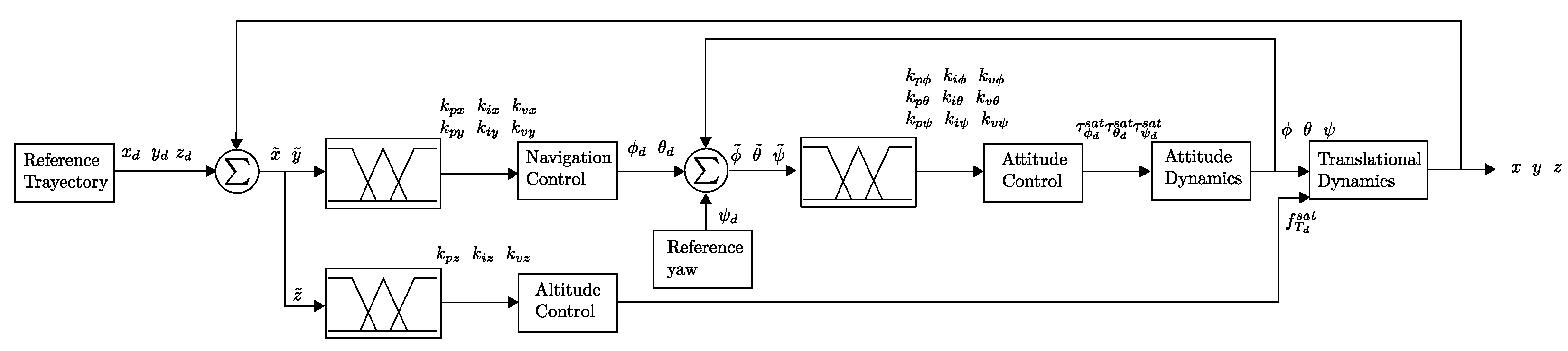
5.3. Trajectory Tracking Navigation
The results of the simulation were obtained using Matlab/Simulink. In previous works, similar algorithms were implemented. In [
21], a quadrotor with a two-layer saturated
PIV controller was shown. The quadrotor follows an ascending helical trajectory which is decreasing. In [
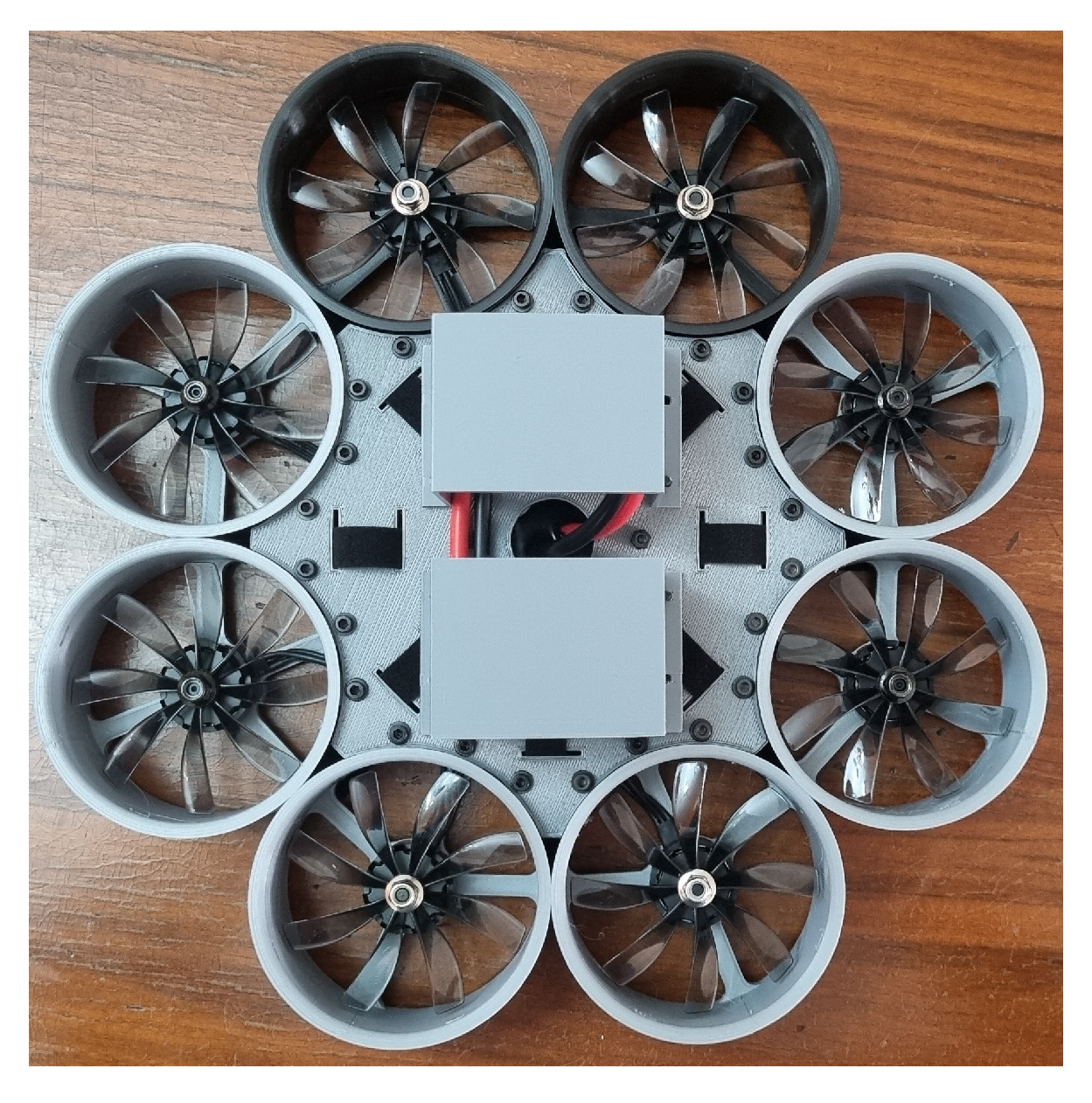
22], an octorotor is proposed using a nonlinear
PV plus a linear integral; in this work, the octorotor has a mass of 8 (kg), and its inertial matrix is simplified. The octorotor follows a helical trajectory, which remains constant during time simulation. The octorotor mini-UAV performs a sequence of movements through the axes traveling 1 m in each axis. The sequence is
, and the negative part of
Z–axis is the take-off. Meanwhile, the positive part is the landing, in the
X–axis, and the positive part is the forward movement, and the negative part is the backward movement. Finally, in the
Y–axis, the positive part indicates the movement from left to right.
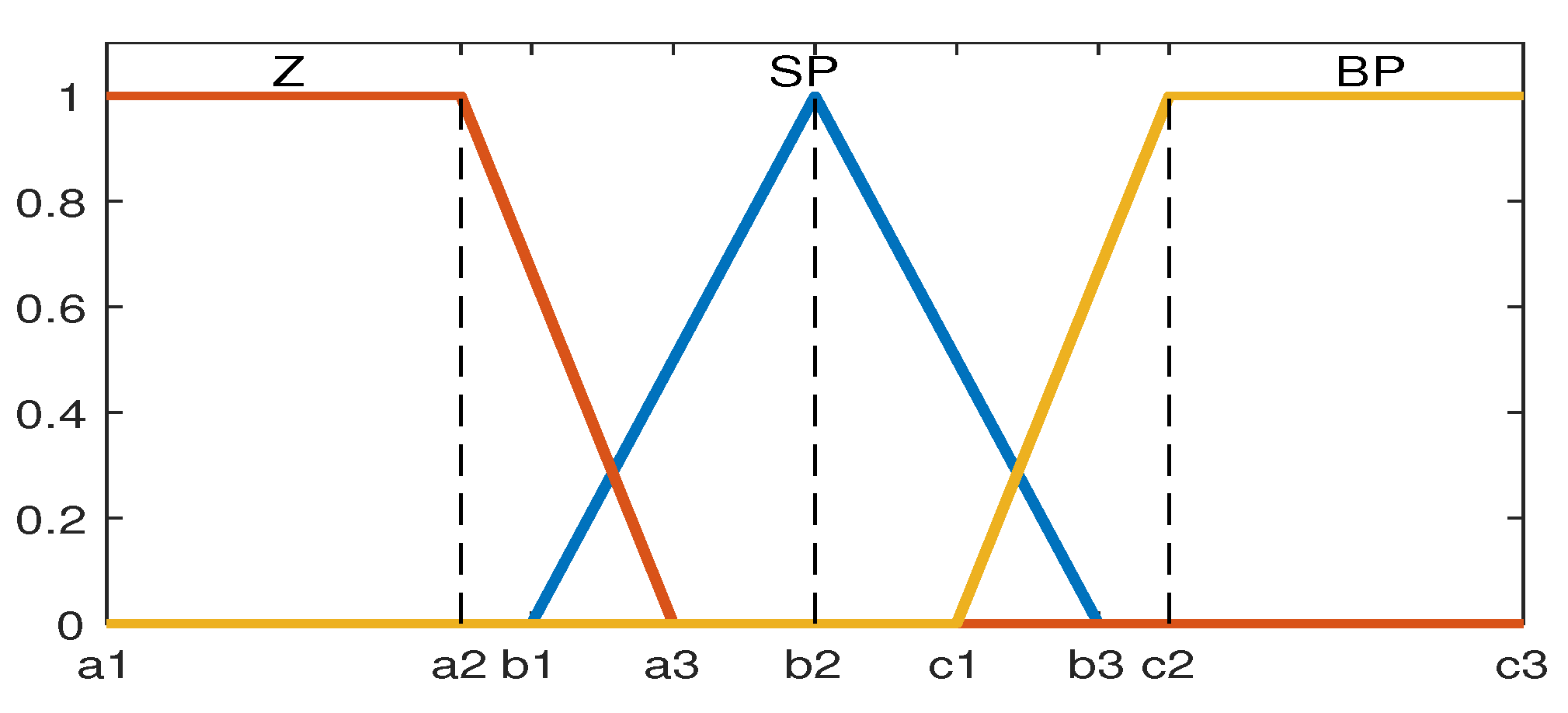
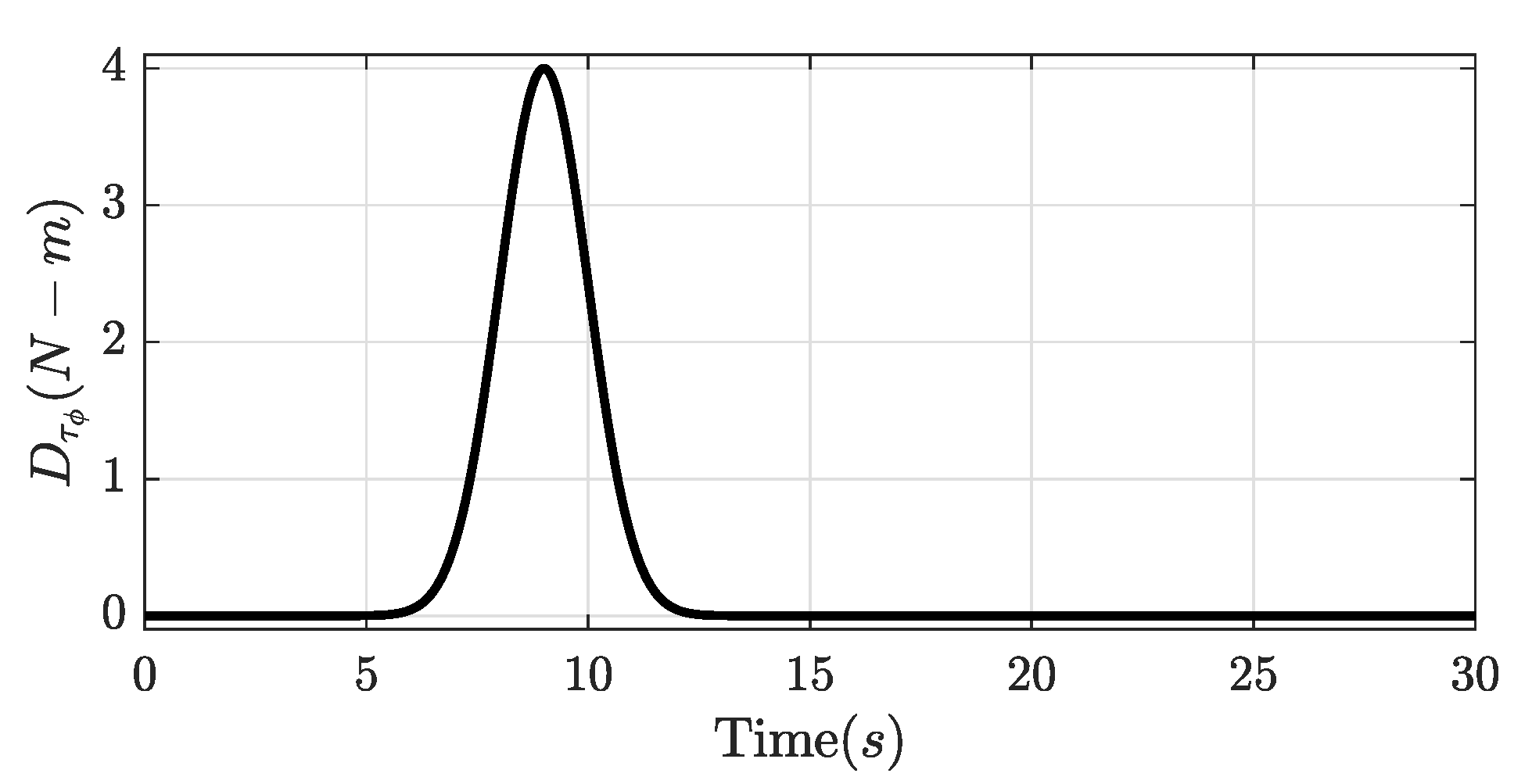
A disturbance is added in Equation (
4), such that
, where
D is the disturbance vector that contains disturbances in each torque. The vector
with
is a Gauss peak equation acting as a disturbance, where
is the height of the peak curve,
is the time where the peak is in the center,
is the standard deviation, and
t is the time, see
Figure 7.
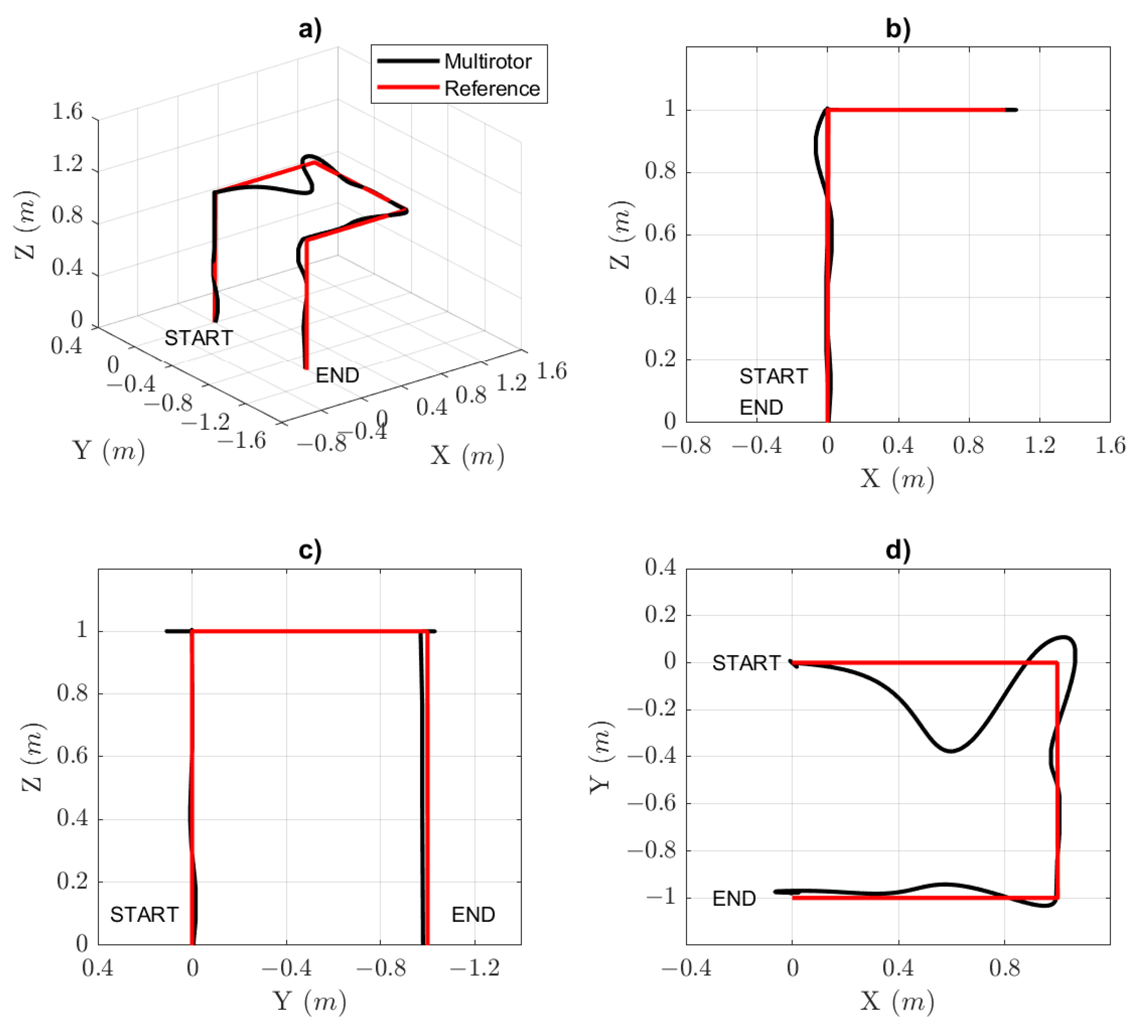
In the simulation,
Figure 8 shows the tracking of the desired (red line) and actual (black line) trajectories of the octorotor mini-UAV. A disturbance is added to analyze the behavior of the gain scheduling controller that autotunes the gains to recover stability in the octorotor mini-UAV. The following
Figure 9 and
Figure 10 show the octorotor mini-UAV in attitude, altitude, and navigation behavior. Then, the rotor speed and gains parameters are shown. Finally, the moments and total thrust of the octorotor mini-UAV are presented.
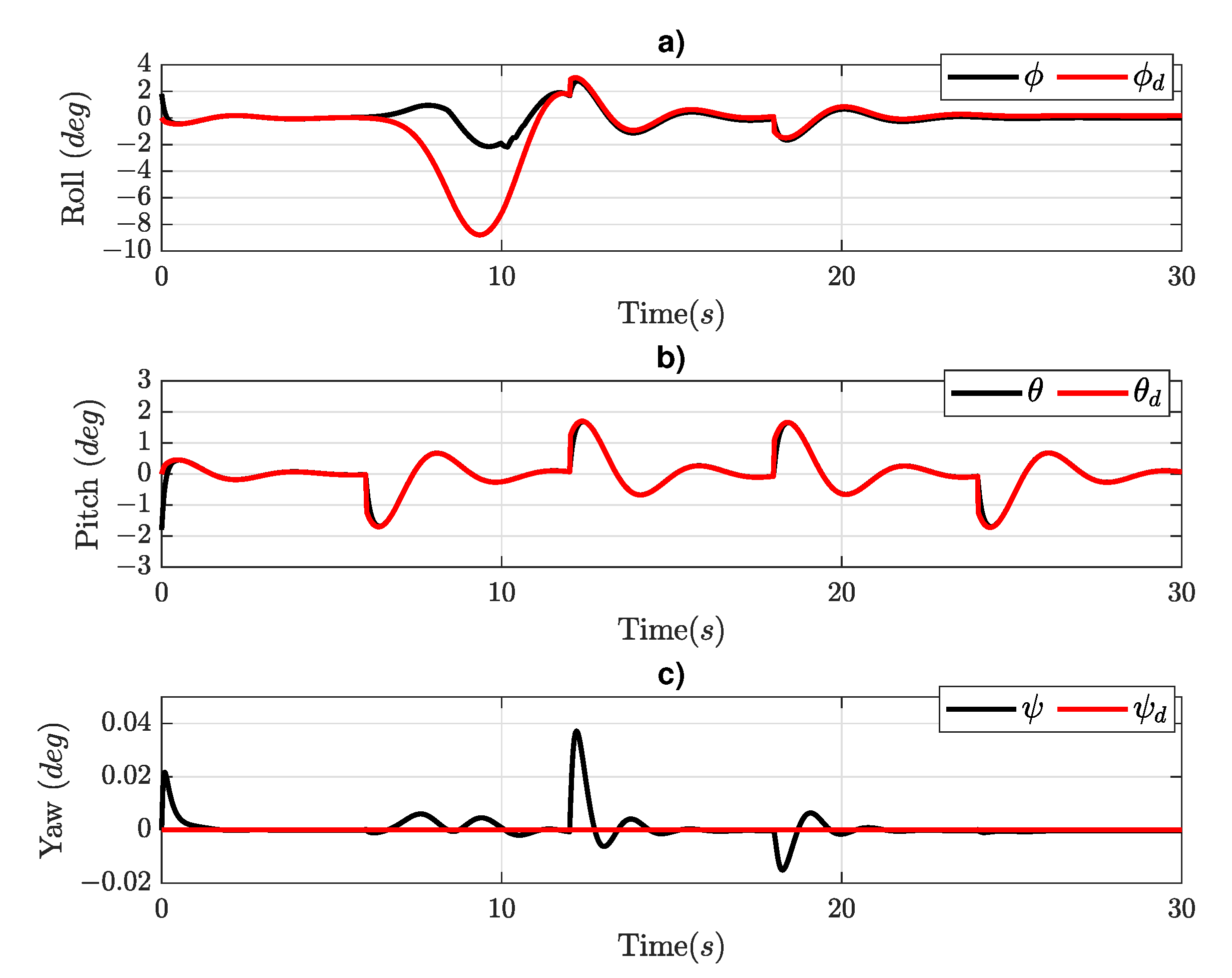
Figure 9 shows the response of Euler angles; in the roll angle (
Figure 9a), the disturbance recalculated the desired value (red line) of the roll angle for a stabilization. While the actual value (black line) continues using less of an angle to recover the trajectory. For the pitch angle (
Figure 9b), there is an absence of disturbance due to this simulation considering the disturbance only in
which indirectly affects the
Y–axis due to the roll angle. There is a small disturbance in the yaw angle (
Figure 9c) when the disturbance in the torque is presented at a time of 9 (s), the following two disturbances are related to the change in direction between the
X and
Y axes at the times of 12 (s) and 18 (s).
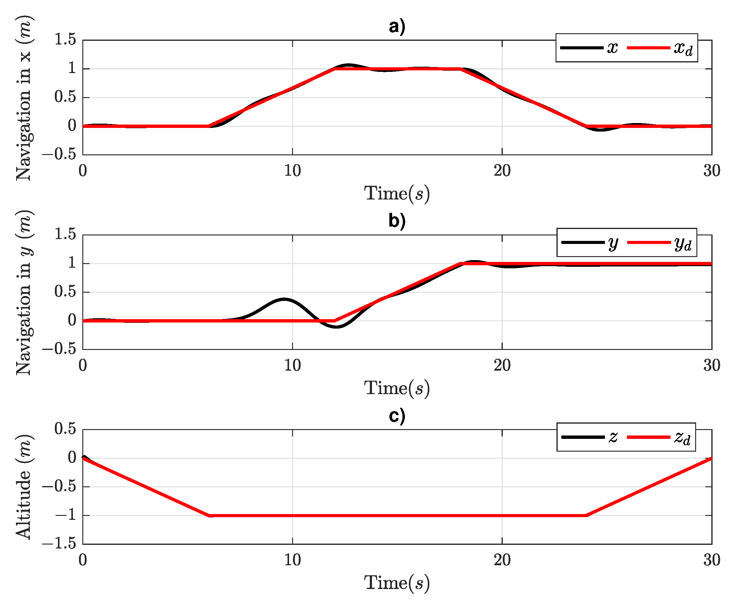
Figure 10 shows the sequence of movements in each axis. In the
X–axis (
Figure 10a), as can be seen, the controller is performs stabilization each time the direction changes due to the attitude controller in
. In the
Y–axis (
Figure 10b), there is a disturbance with a peak at 9 (s) due to the disturbance in
. Finally, the
Z–axis (
Figure 10c) presents rapid stabilization during ascending and descending.
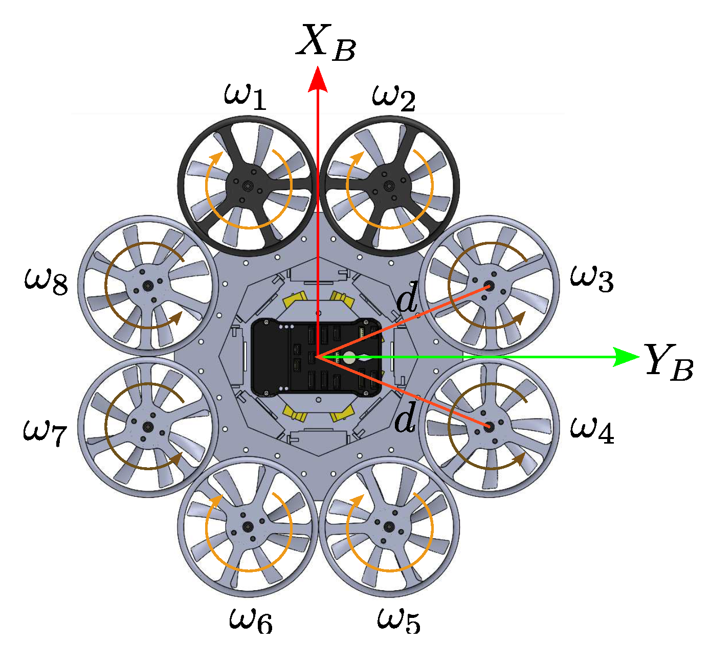
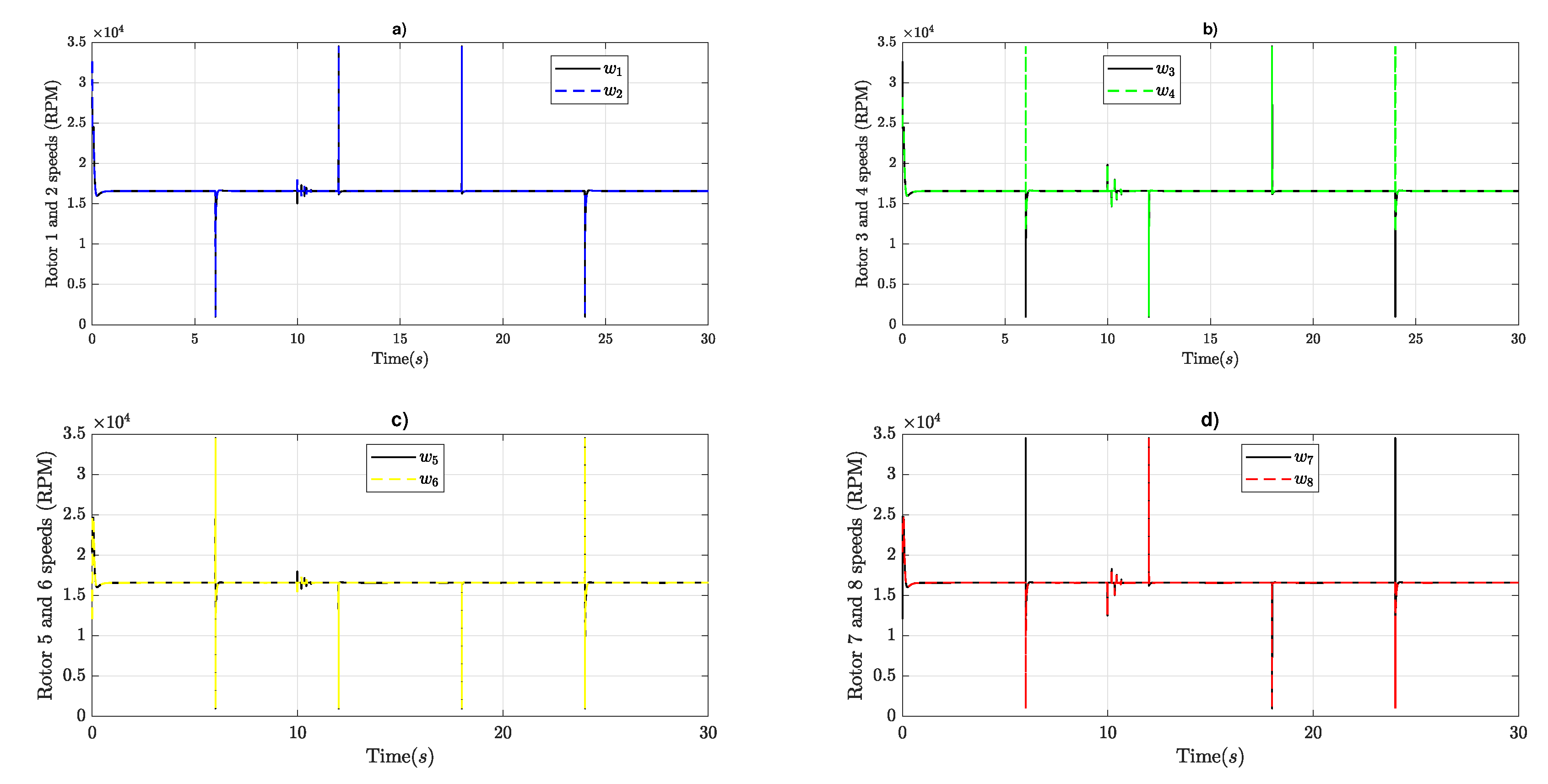
Figure 11 shows the angular velocity in RPM of all rotors, which have a maximum speed limit set to 34,500 (RPM), as obtained in the datasheet of the motor, and a minimum speed limit set to 1000 (RPM), to avoid turning off the rotors. The regulated speed after stabilization is 16,570 (RPM) in each rotor. All rotors are paired in two in the sense that
,
,
, and
present a similar behavior with a small difference when the octorotor mini-UAV is changing direction. When the octorotor mini-UAV ascends, the whole rotors are stabilized at 16,570 (RPM), and then, in the
X–axis forward direction, rotors
and
(
Figure 11a) increase their speed and
and
(
Figure 11c) decrease their speed. When the octorotor mini-UAV changes direction towards the east, rotors
and
(
Figure 11d) increase their speed and
and
(
Figure 11b) decrease their speed.
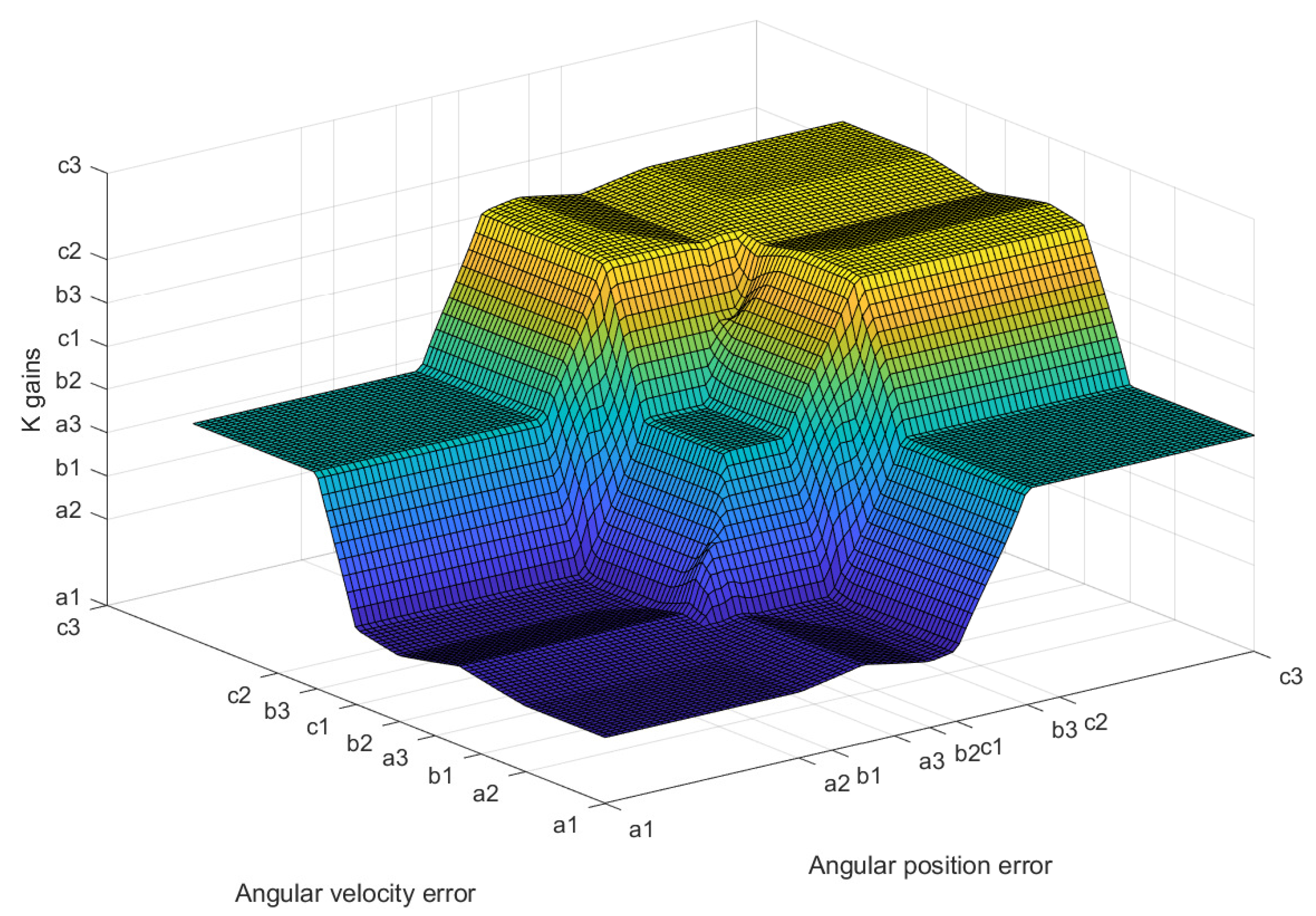
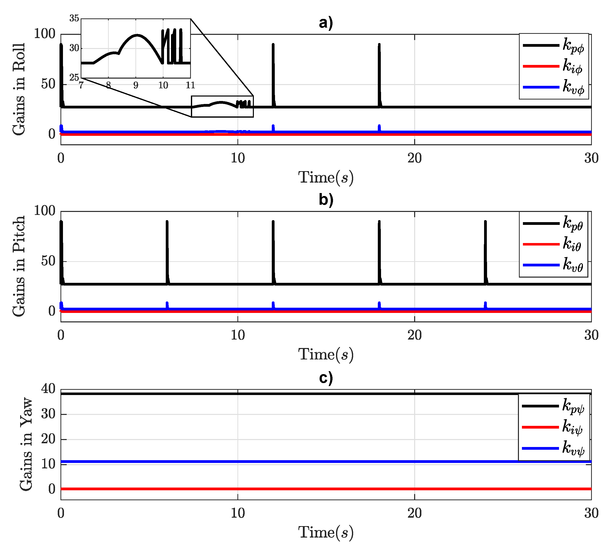
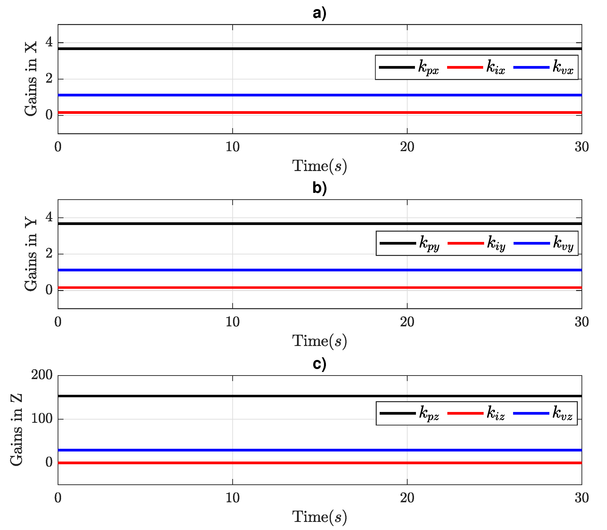
Figure 12 shows the gain behavior in the attitude controller.
Figure 12a illustrates the gains of
controller, where the proportional gain changes by the disturbance set. For each change in direction, the proportional and velocity gains change. The gains of the
controller (
Figure 12b) present the same behavior when the octorotor mini-UAV changes direction, except that there is no disturbance in
. In the
controller, the gains (
Figure 12c) remain constant due to the desired yaw set to zero.
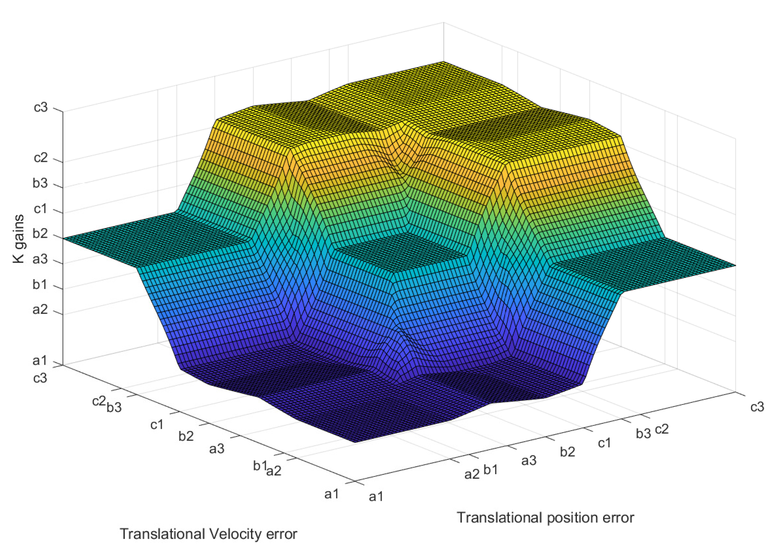
Figure 13 shows the gain behavior in the translation controller. Due to the gain in attitude adjusting, the gains in the translation controller remain constants without changes.
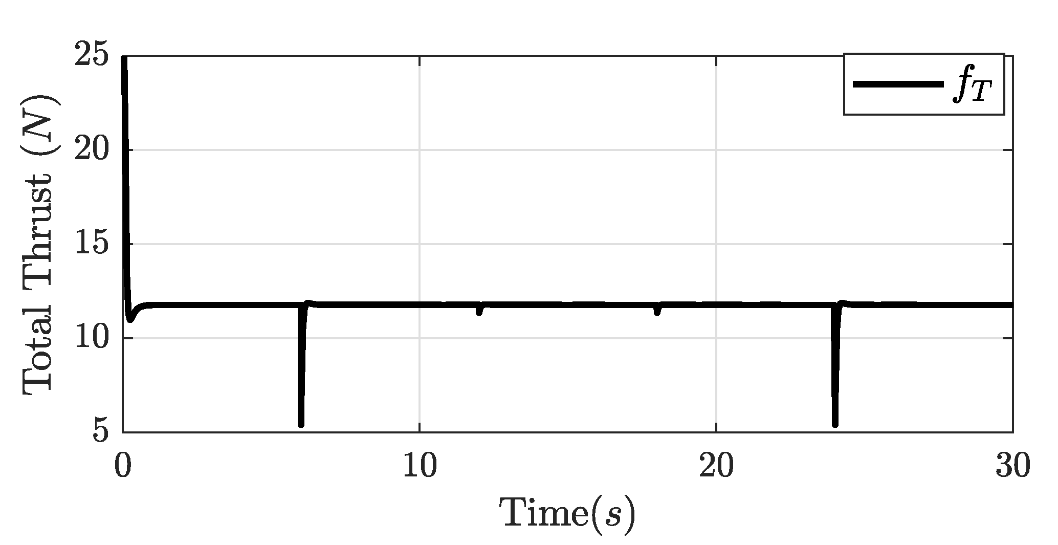
Figure 14 shows the total thrust of all rotors in the octorotor mini-UAV. The maximum thrust shown is 22.55 (N) at the beginning, and then the stable thrust is 11.77 (N), which is the minimum to maintain the octorotor mini-UAV hovering during flight. The minimum total thrust shown is 5.45 (N) due to the finalization of ascending and when it starts descending.
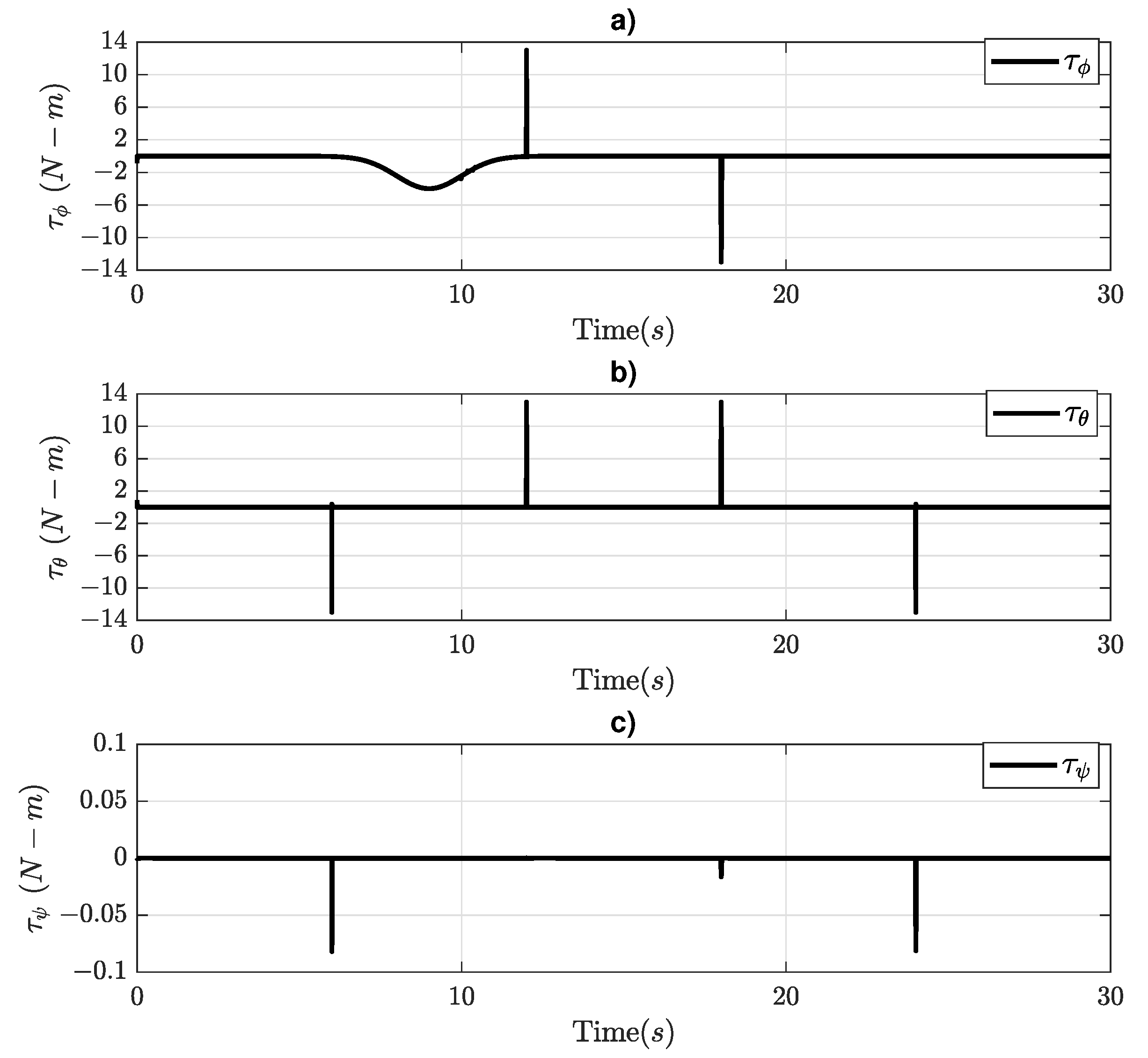
Figure 15 shows moment actuators in the octorotor mini-UAV, where
has the disturbance added at 9 (s) to a disturbated
Y–axis as it can be seen in
Figure 15a. Then,
Figure 15b shows the moment
when the octorotor mini-UAV performs the
X–axis movements. Then,
Figure 15c illustrates the
signal with a minimum actuation when the octorotor mini-UAV stops ascending when the octorotor mini-UAV performs the
Y–axis movement. Finally, when the octorotor mini-UAV starts descending, these actions affect the yaw angle between
and
.


